

Page 1
MONITOR CONTROL UNIT
BKM-10R
MONITOR CONTROL UNIT
BKM-11R
電気製品は、安全のための注意事項を守らないと、人身
警告
このオペレーションマニュアルには、事故を防ぐための重要な注意事項と製
品の取り扱いかたを示してあります。このマニュアルをよくお読みのうえ、
製品を安全にお使いください。お読みになったあとは、いつでも見られるよ
うに必ず保管してください。
OPERATION MANUAL
事故になることがあり、危険です。
[Japanese/English]
1st Edition
Serial No. 2000001 and Higher
Page 2
警告
電気製品は正しく使用すれば事故が起きないように、安全には充分配慮して
設計されています。しかし、まちがった使いかたをすると、火災や感電など
により死亡や大けがなど人身事故につながることがあり、危険です。
事故を防ぐために次のことを必ずお守りください。
安全のために
安全のための注意事項を守る
2(J)〜4(J)ページの注意事項をよくお読みください。
警告表示の意味
このオペレーションマニュアル
および製品では、次のような表
示をしています。表示の内容を
よく理解してから本文をお読み
ください。
定期点検をする
5年に1度は、内部の点検を、お買い上げ店またはソニーのサービス窓口にご
依頼ください(有料)。
故障したら使わない
すぐに、お買い上げ店またはソニーのサービス窓口にご連絡ください。
万一、異常が起きたら
・煙が出たら
・異常な音、においがし
たら
・内部に水、異物が入っ
たら
・製品を落としたり、
キャビネットを破損し
たときは
1 電源を切る。
/
2 お買い上げ店またはソニーの
サービス窓口に連絡する。
警告
この表示の注意事項を守らない
と、火災や感電などにより死亡
や大けがなど人身事故につなが
ることがあります。
注意
この表示の注意事項を守らない
と、感電やその他の事故により
けがをしたり周辺の物品に損害
を与えたりすることがありま
す。
注意を促す記号
注意
行為を禁止する記号
火災
感電
この装置は、情報処理装置等電波障害自主規制協議会(VCCI)の基準に
基づくクラスA情報技術装置です。この装置を家庭環境で使用すると電波
妨害を引き起こすことがあります。この場合には使用者が適切な対策を講
ずるよう要求されることがあります。
禁止
行為を指示する記号
強制
分解禁止
Page 3

目次
警告 ........................................................................................................................
注意 ........................................................................................................................
モニターコントロールユニット
概要...................................................................................................................... 5 (J)
各部の名称と働き............................................................................................... 5 (J)
モニターメモリーカー ドの取り扱い ..................................................................... 9 (J)
ラックへの取り付け............................................................................................ 10 (J)
モニターとの接続 .............................................................................................. 11 (J)
仕様.................................................................................................................... 11 (J)
モニターコントロールユニット
概要.................................................................................................................... 12 (J)
各部の名称と働き............................................................................................. 12 (J)
接続.................................................................................................................... 13 (J)
モニターメモリーカー ドの取り扱い ................................................................... 13 (J)
仕様.................................................................................................................... 13 (J)
BKM-10R
BKM-11R
..........................................................
.......................................................
2(J)
3(J)
5 (J)
12 (J)
日
本
語
1 (J)
Page 4
警告
分解禁止
禁止
禁止
下記の注意を守らないと、
感電火災
火災や感電により死亡や大けがにつながることがあります。
キャビネットをはずさない、改造しない
分解や改造をすると、火災や感電、けがの原因となることがあります。内部
の調整や設定、点検、修理は、お買い上げ店またはソニーのサービス窓口に
ご依頼ください。
内部に水や異物を入れない
水や異物が入ると火災や感電の原因となります。
万一、水や異物が入ったときは、すぐに電源を切り、接続ケーブルを抜い
て、お買い上げ店またはソニーのサービス窓口にご相談ください。
油煙、湯気、湿気、ほこりの多い場所では設置・使用しない
上記のような場所に設置すると、火災や感電の原因となります。
このマニュアルに記されている仕様条件以外の環境での使用は、火災や感電
の原因となります。
2(J)
Page 5
下記の注意を守らないと、
注意
けがをしたり周辺の物品に損害を与えることがあります。
規定の電源電圧で使う
このマニュアルに記されている電源電圧でお使いください。
強制
放熱に気を配る
内部に熱がこもると、火災や故障の原因となることがあります。次の項目を
禁止
お守りください。
・ 壁から 10cm 以上離して設置する。
・ 密閉された狭い場所に押し込めない。
・ 毛足の長い敷物(じゅうたんや布団など)の上に設置しない。
・ 布などで包まない。
・ あお向けや横倒し、逆さまにしない。
不安定な場所に設置しない
禁止
ぐらついた台の上や傾いたところなどに設置すると、落ちたり、倒れたりし
て、けがの原因となることがあります。
また、設置・取り付け場所の強度を充分にお確かめください。
3(J)
Page 6
下記の注意を守らないと、
注意
けがをしたり周辺の物品に損害を与えることがあります。
転倒、移動防止の処置をする
ラックに取り付け・取りはずしするときは、転倒・移動防止の処置をしない
注意
禁止
注意
と、倒れたり、動いたりして、けがの原因となることがあります。
安定した姿勢で注意深く作業してください。
また、ラックの設置状況、強度を充分にお確かめください。
上に乗らない、重い物を載せない
倒れたり、落ちたり、壊れたりして、けがの原因となることがあります。
お手入れの際は、電源を切る
電源を入れたままお手入れをすると、感電の原因となることがあります。
注意
注意
移動させるときは接続ケーブルを抜く
接続したまま移動させると、接続ケーブルが傷つき、火災や感電の原因とな
ることがあります。
定期的に内部の掃除を依頼する
長い間掃除をしないと内部にホコリがたまり、火災や感電の原因となること
があります。1年に1度は、内部の掃除をお買い上げ店またはソニーのサー
ビス窓口にご依頼ください(有料)。
特に、湿気の多くなる梅雨の前に掃除をすると、より効果的です。
4(J)
Page 7
モニターコントロールユニット
概要
モニター コントロールユニットBKM-10Rは、ソニーBVMシリーズお
よびHDMシリーズカラービデオモニター用のコントロールユニット
です。電源の入/切やメニュー操作などのモニターの動作をコント
ロールするとともに、モニターの調整やセットアップを実行します 。
BKM-10Rには以下のような特長があります。
複数のモニターを統括管理
1台でモニターを32台まで操作できます。各モニター には、あらか
じめメ ニュ ーでアドレスNo.を割り付けたり、数台をグループ化し
て、グループNo.を割り付けておくことが できます 。アドレスNo.や
グループNo.を指定して、特定のモニターまたは特定のグループ
のモニターだけを操作するこ と ができ ます。また、 接続しているす
べてのモニターの調整・セットアップ状 態を統一したり、同時に 同
じ動作を実行させることも可能です。
BKM-10R
インチモニターと連結可能
20
別売りのモニターコン トロールユニットアタ ッチメントキッ トBKM-32H
を使って 、BVM-20F1Jなどのモニターと一体化して使うこともでき
ます。
インチモニターと連結可能
24
別売りのモニターコン トロールユニットアタ ッチメントキッ トBKM-34H
を使って 、BVM-D24E1WJと一体化して使うこと もでき ます。
ラックマウント可能
別売りのラックマウントキッ トMB-510と付属のラックマウントブラケッ
ト 取 り 付けネジ を使って、EIA標準19インチラックに取り付けること
ができます。
モニターメモリーカードによる調整・セットアップ
別売りのモ ニターメモリーカー ドBKM-12Yにモニターの調整・セッ
トアップ状態のデータを保存することができます 。複数のモニターを
操作している場合、モニターメモリーカードを使って、モニター間で
データのや りとりが可能です。同じ調整 ・セッ トアップ状態を 容易に
再現でき、モニター間で調整・セッ トアップ状態をそろえることがで
きます。
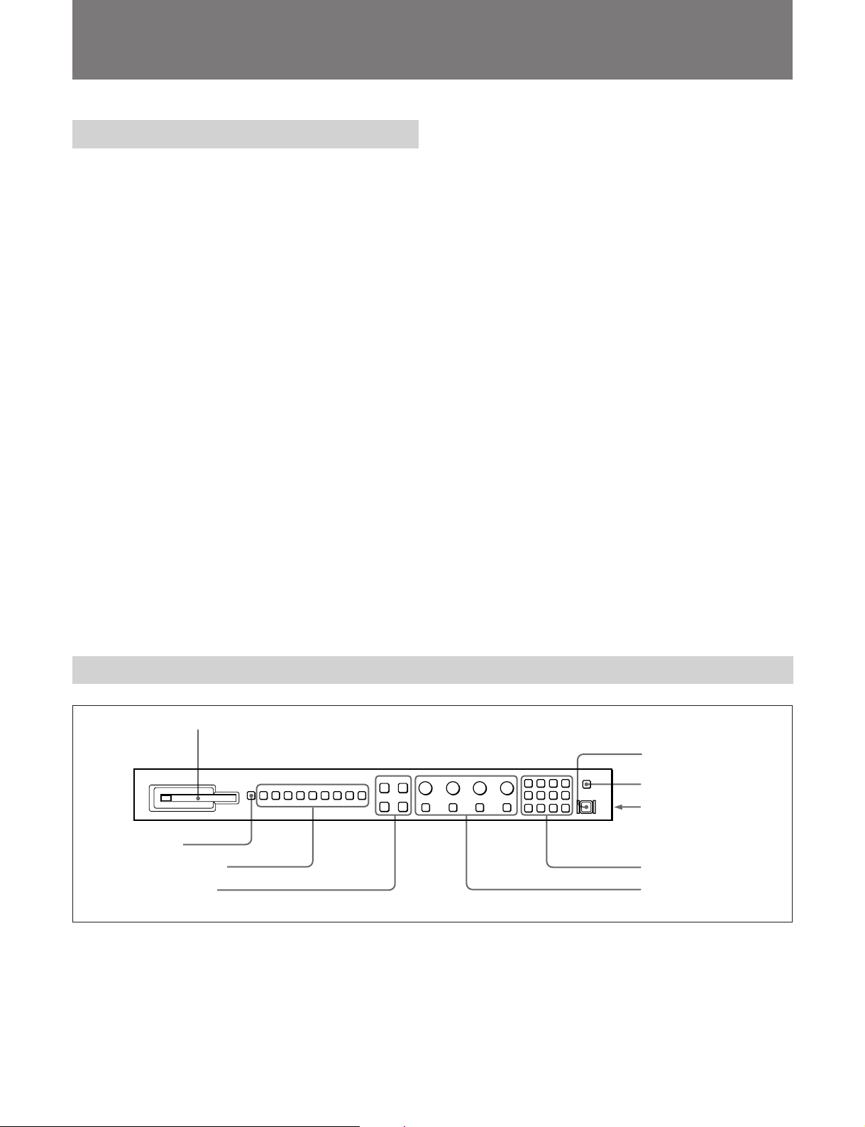
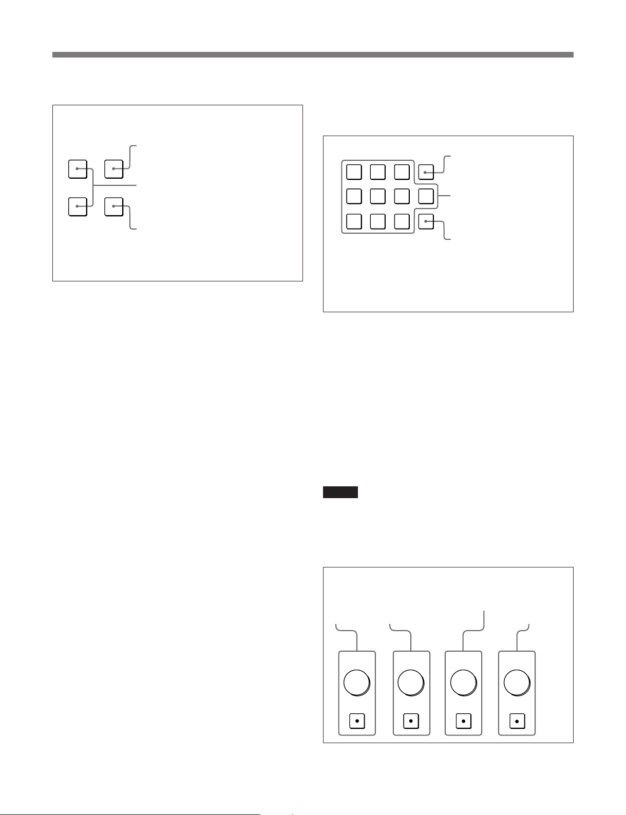
各部の名称と働き
1 モニターメモリーカード挿入口
2
3 ファンクションボタン
4 メニュー操作ボタン
SHIFT
ボタン
5
POWER
6
DEGAUSS
7
DISPLAY UNIT
(後面)
8 テンキー部
9
MANUAL
つまみ
スイッチ
ボタン
端子
調整ボタンと
モニターメモリーカード挿入口
1
別売りのモ ニターメモリーカー ドBKM-12Yを挿入します。
SHIFT (
2
このボタン を押して、ファンクションボタ ン3に割り付けられている
2種類の機能のうちどちらを使うか選択します。
シフト)ボタン
押すたびに、ボタン上のLED(オレンジ)がついたり(シフトON)、
消えた り (シフトOFF)します。
シフト
シフト
のとき :各フ ァンク ションボタンの下側に表示 されてい
ON
る機能が使えます。
のとき:各フ ァンク ションボ タンの上側に表示されてい
OFF
る機能が使えます。
5 (J)
Page 8
モニターコントロールユニット
BKM-10R
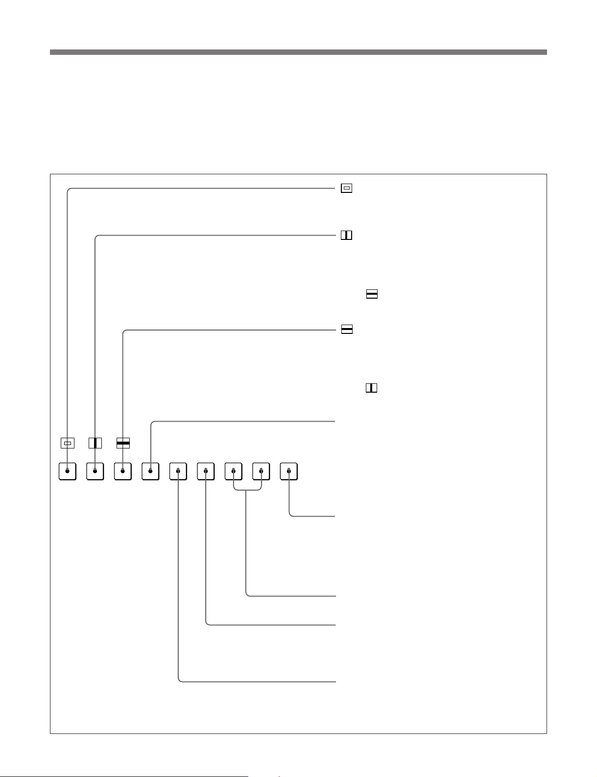
ファンクションボタン
3
モニターの動作条件を切り換えます。
押すたびに、ボタン上のLEDが点いたり (ON)、消えたり(OFF)
して、モニターの動作条件が切り換わります。
シフト
の場合(緑の
OFF
LED)
各ボタンには2種類の機能が割り付けられています。SHIFTボタン
をON/OFFして、どちらの機能を使うか選択します。シフトOFFの
場合は、各ボタンのLEDの色が緑に、シフトONの場合は、 各ボ タ
ンのLED の色がオレ ン ジ にな ります。
アンダースキャン)ボタン:ONにすると、3%ア
(
ンダースキャンになり、ラスターの四隅までが画
面に表示されます。
ディレイ)ボタン:ONにすると、画像が水平方
(H
向に移動し、画面の左から約
期信号が現われます。
画像の明るさ(輝度)が自動的に増加して、同期
•
部分のチェックに便利です。
ボタンと併用すると、パルスクロス画像が
•
表示されます。
ディレイ)ボタン:ONにすると、画像が垂直
(V
方向に移動し、画面のほぼ中央に垂直同期信号が
現われます。
画像の明るさ(輝度)が自動的に増加して、同期
•
部分のチェックに便利です。
ボタンと併用すると、パルスクロス画像が
•
表示されます。
の位置に水平同
1/4
16 : 9
SYNC
BLUE
ONLY
MONO
R
APT COMB
GBF3
F1
F2 ADDRESS
SAFE
F4
AREA
MONO (白黒)
なります。
の有無により、画面は自動的にカラーまたは白黒
に切り換わります。
ADDRESS (
に
ADDRESS
を操作するときの動作条件を設定します。
◆
ボタン:将来の拡張用です。
F1/F2
COMB (
ターを
コーダーアダプター(別売り)を装着していると
きに機能します。
アパーチャー)ボタン:ONにすると周波数特性
APT(
を補正できます。補正量はメニューで設定しま
す。
売り)を装着しているときに機能します。
ボタン:ONにすると、画面が白黒に
にすると、カラーバースト信号
OFF
アドレス)ボタン:ONにすると、画面
ADDRESS
ADDRESS
るモニターの取扱説明書をご覧ください。
くし型フィルター)ボタン:くし型フィル
BKM-24N
メニューが表示されます。
メニューを使って、複数のモニター
メニューについては、使用してい
ON/OFF
します。
などのデコーダーアダプター(別
BKM-24N
などのデ
6 (J)
Page 9
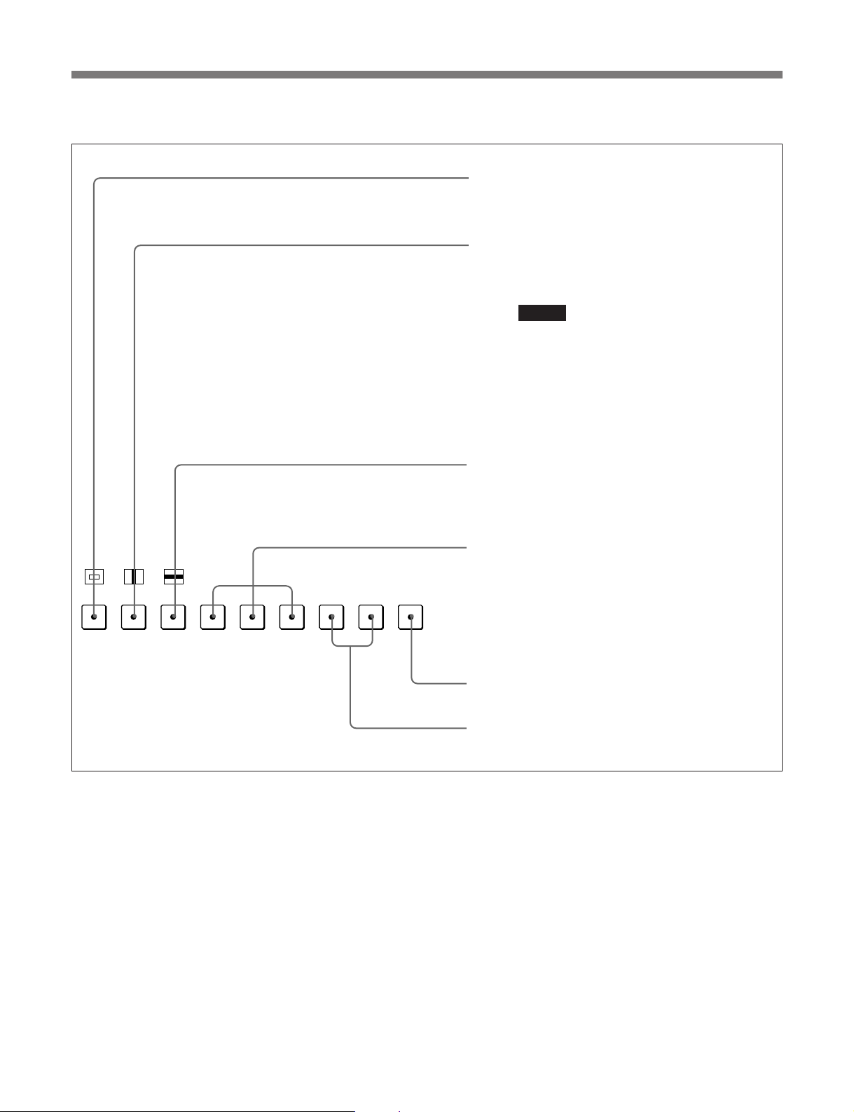
シフトONのとき(オレンジの
LED)
MONO
APT COMB
F1
F2 ADDRESS
ボタン:ONにすると画面のアスペクト比が
16:9
にすると
OFF
SYNC (
シンク)ボタン:ONにすると、モニター後面の
端子に入力されている同期信号に同期します
SYNC
(
EXT SYNC)。OFF
に含まれている同期信号に同期します(
ご注意
• INT SYNC
またはYC信号をモニターするときは、Y信号に同
期信号を付加してください。また、
ニターするときは、G信号に同期信号を付加して
ください。
シリアルデジタル信号をモニターするときは、常
•
に
INT SYNC
BLUE ONLY(
号がカットされ、青信号のみが白黒画像として表示され
ます。クロマやフェーズの調整、
クに便利です。
ボタン:ONにすると、R(赤)、G(緑)、B(青)の
R/G/B
ビームをカットします。
になります。
4:3
にすると、モニターしている信号
INT SYNC
を選択した場合、コンポーネント信号
RGB
が選択されます。
青色表示)ボタン:ONにすると、赤と緑の信
ノイズのチェッ
VTR
に、
16:9
信号をモ
)。
16 : 9
SYNC
BLUE
ONLY
R
GBF3
SAFE
F4
AREA
SAFE AREA(
リアが表示されます。
ボタン:将来の拡張用です。
F3/F4
セーフエリア)ボタン:ONにするとセーフエ
7 (J)
Page 10
モニターコントロールユニット
INPUT
1
2
3
Del
4
5
6
0
7
8
9
Ent
BKM-10R
メニュー操作ボタン
4
ボタン:押すとメニューが表示
UP MENU
DOWN
◆メニューについて詳し く は、モニターの取扱説明書をご覧ください。
ENTER
5 POWER (
MENU
されます。
UP/DOWN
を選択します。
ENTER
定値を確定します(テンキー部8
の
電源)スイッチ
ボタン:項目および設定値
ボタン:選択した項目および設
ボタンも同じ働きをします)。
Ent
押すたびにモニターの電源を入/切します。モニターを複数台接
続してい るときは 、ADDRESSメニューの設定により、全モニター
の電源を同時に入/切することがで きます。
◆ ADDRESSメニューについては、使用しているモニターの取扱説明書
をご覧ください。
6 DEGAUSS (
消磁)ボタン
押すとCRTが消磁されます (モニターの電源を入れるたびに、
CRTは自動的に消磁されます)。再度消磁するときは、5分以上間
隔をおいてください。
DISPLAY UNIT (
7
ディスプレイユニット)端子(後面
)
別売りのRCC-5G/10G/30GケーブルまたはBKM-32H/34Hに付
属のケーブルで、BVM-20F1J/14F1Jなどの操作部分離型モニ
ターのCONTROLUNIT端子と接続します。
この端子を介して、モニターからBKM-10Rに電源を供給したり、
コン トロール信号の受け渡しを行います。
テンキー部
8
モニターしたい入力信号のチャンネル番号を指定したり、メニュー
で設定値を入力するときに使います。
ボタン:入力した数値や
Del
文字を消去します。
数値ボタン
ボタン:入力した数値や
Ent
文字を確定します(メ
ニュー操作ボタン4の
ボタンも同じ働
9 MANUAL (
ENTER
きをします)。
手動)調整ボタンとつまみ
ボタンを押すたびに、ボタン上のLED(緑) が点いたり(ON)、消
えたり(OFF)します。ONにすると、画面のコントラスト、明るさ ( 黒
レベル)、クロマ(色の飽和度)、フェ ーズ (色相) を、それぞれつま
みで調整できます。また、PHASE (フェーズ) 調整つまみはメ
ニューで設定値を入力するときにも使います。
各調整項目は、CONTROLPRESETADJメニューでプリセット値
を設定して おくことが できます。
◆ CONTROLPRESETADJメニューに ついては、使用しているモニター
の取扱説明書をご覧ください。
ご注意
コ ンポジットSECAM、コンポジットPALD、コンポーネントまた は
SDI (コンポーネント ま たはコ ンポジ ットシリア ル デ ジタルインター
フェース) フォーマット では、フェーズを調整できません。また、RGB
信号のフ ェ ーズおよびク ロマ を調整でき ま せん。
PHASE
フェーズ
(
調整ボタン
とつまみ
CHROMA
クロマ)調
(
)
整ボタンと
つまみ
BRIGHT
明るさ)調整ボ
(
タンとつまみ
CONTRAST
コントラスト
(
調整ボタンと
つまみ
)
PHASE
MANUAL MANUAL MANUAL MANUAL
8 (J)
CHROMA
BRIGHT
CONTRAST
Page 11
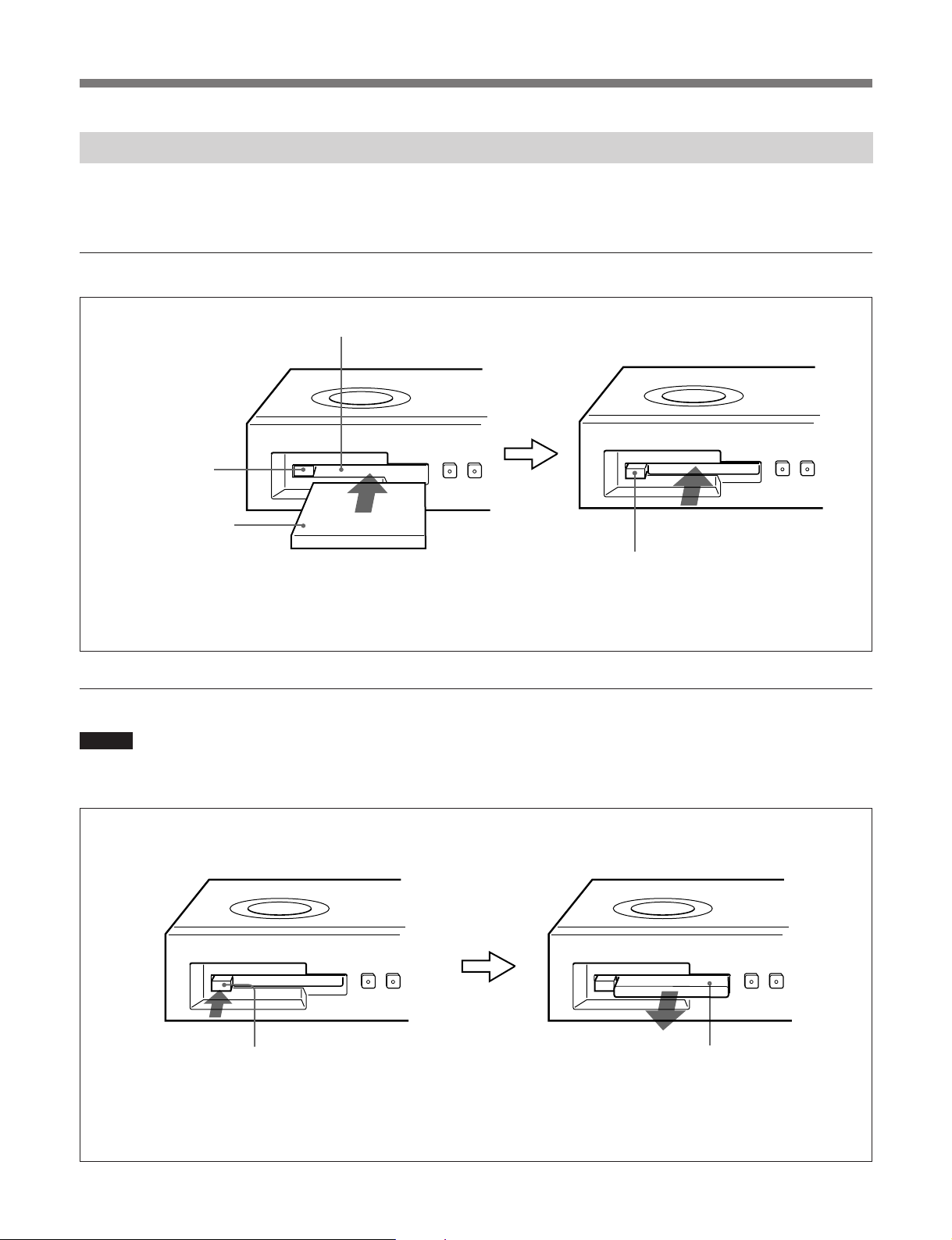
モニターメモリーカードの取り扱い
別売りのモニターメモリーカードBKM-12Yは、以下の方法で
BKM-10Rに出し入れします。
入れかた
モニターメモリーカード挿入口
ボタン
EJECT
モニターメモリー
カード
モニターメモリーカードのコネク
ター部(先端部)に手をふれないよ
うにご注意ください。
◆ モニターメモ リ ーカードのデータ 操作については、使用しているモニター
の取扱説明書をご覧ください。
ボタンが外に出るまで、
EJECT
モニターメモリーカードを押し込
みます。
取り出しかた
ご注意
モニターメモリ ーカー ドが動作しているとき(データのセーブ・ロー
ド中 ) には、モニターメモリーカー ドを取り出さない でく ださい。
ボタン
EJECT
ボタンを押すと、モニターメモリー
EJECT
カードの先端部が挿入口から出てきます。
モニターメモリー
カードを取り出し
ます。
9 (J)
Page 12

モニターコントロールユニット
BKM-10R
ラックへの取り付け
BKM-10RをEIA標準19インチラッ クに取り付けるには、別売りの
ラックマウントキッ トMB-510が必要です。
以下の手順で取り付けます。
1 BKM-10R底面の足 (4個) を取り外
す。
2 ラックマウントキッ トMB-510 (別売り)
のラ ッ クマウ ントブラケッ トを、付属の
ラッ クマウントブラケ ット取り付けネジで
BKM-10Rの両側面に取り付ける。
ラックマウント
ブラケット
BKM-10R/
ラックマウント
ブラケット取り
付けネジ
3 ラックマウントブラケッ トをラ ックにネジ
止めして、BKM-10Rをラックに取り付
ける (ラックの ネジ穴に合った市販の
ネジをお使いください)。
ラック
10 (J)
Page 13

モニターとの接続
本機のDISPLAYUNIT端子とモニターのCONTROLUNIT端子
を、 別売り のコントロールケーブルで接続します。
ご注意
モニターのMAINPOWERスイッチをオフにした
状態で接続を行ってください。
本機
モニター
DISPLAY UNIT
ピンリモートコントロールケーブル
9
端子
仕様
一般
電源 DC5V (接続しているモニターより供給)
消費電力 0.5W
最大0.7W
最大外形寸法 424×44×157mm (幅/高さ/奥行き)
質量 1.4kg
動作条件
RCC-1G/5G/10G/30G (
コントロール端子
DISPLAYUNIT D-sub9ピン×1
付属品
ラックマウントブラケッ ト 取 り 付けネ ジ (4)
オペ レーションマニュアル (1)
別売り
CONTROL UNIT
)
端子
温度 0〜35℃
推奨使用温度 20〜30℃
湿度 0〜90%以下 (結露のないこと)
気圧 700〜1060hPa
保存・輸送条件
温度 −10〜+40℃
湿度 0〜90%
気圧 700〜1060hPa
別売りアクセサリー
モニターメモリ ーカー ドBKM-12Y
ラックマウントキッ トMB-510
9ピンリモートコントロールケーブルRCC-1G/5G/10G/30G
関連機器
カラービデオモニターBVM-20F1J/14F1J/20E1J/14E1J/
20G1J/14G1J、BVM-D24E1WJ/D20F1J/D14H1J/D9H1J、
HDM-20E1J/14E1J
本機の仕様および外観は、改良のため予告なく変更することがあ
ります が 、こ了承く ださい。
11 (J)
Page 14

モニターコントロールユニット
モニターコントロールユニット
BKM-10R
概要
BKM-11R
モニ ター コントロールユニットBKM-11Rは、ソニーBVMシリーズお
よびHDMシリーズカラービデオモニター用のコントローラーです。
電源の入/切やメニ ュー操作などのモニターの動作をコントロール
するとともに、モ ニターの 調 整 や セッ トアップ を 実 行します。
BKM-11Rには以下のような特長があります。
複数のモニターを統括管理
1台でモニターを32台まで操作できます。各モニターには、あらか
じめメ ニュ ーでアド レ スNo.を割 り 付けたり 、数台をグループ化し
て、グループNo.を割り付けておくことが できます 。アドレスNo.や
グループNo.を指定して、特定のモニターまたは特定のグループ
のモニターだけを操作するこ とができます。 また、 接続しているす
べてのモニターの調整・セットアップ状態を統一したり、同時に同
じ動作を実行させることも可能です。
ご注意
BKM-11Rとモニターの接続には、必ず付属のケーブルをご使
用く ださい。他のケーブルを使用する場合は、 BKM-11Rは、
EEC Directive89/336/EECの規格に適合しない可能性があ
ります 。
モニターメモリーカードによる調整・セットアップ
別売りのモ ニターメモリーカー ドBKM-12Yにモニターの調整・セッ
トアップ状態の データを保存すること ができます。複数のモニターを
操作 してい る場合、モニターメモリーカー ドを使って、モニ ター間で
デー タ のやりとりが可能です。同じ調整・セッ トアップ状態を容易に
再現でき、モニター間で調整・セッ トアップ状態をそろえることがで
きます。
OPTION
モニター本体と同じOPTION端子を装備しています。この端子に
オートセットアッププローブBKM-14Lを接続すると、ホワイトバラン
スの自動調整ができ、さらに色度座標(x、y)と輝度(Y)を表示で
きるようになります 。また、 カラーアナライ ザーを接続して、ホワイト
バランスの自動調整を行うことが できます 。 接続できるカラーアナラ
イザー は、SLS 9400 (GRASEBY OPTRONICS)、PM 5639
(PHILIPSTVTESTEQUIPMENT)、CA-100 (MINOLTA)、TF6
(THOMALichtmesstechnik) などです。
◆ BKM-14Lおよびホワイトバランスの自動調整の操作については、使用
端子を装備
しているモニターのオペレーションマニュアルをご覧ください。
各部の名称と働き
操作パネル:
つまみがあります。これらの名称と働きについて
は、
5 (J)
OPTION (
(Mini DIN 8ピン)
ナライザーを接続します。
MONITOR (
(D-sub 9ピン)
ブルで、モニター前面の
OPTION
BKM-10R
ページをご覧ください。
オプション)端子
モニター)端子
:付属のケー
端子と接続します。
と同じボタン、スイッチ、
:カラーア
モニターメモリーカード挿入
口:モニターメモリーカード
を挿入します。
スイッチ:”の方向にスライド
EJECT
すると、モニターメモリーカードを取
り出せます。
12 (J)
Page 15

接続
取り出しかた
本機をモ ニターと下図のように接続します。ホワイトバランスの自動
調整を行うときは、さらにカラ ーアナライ ザーを接続します。
モニター
OPTION
OPTION
端子
本体接続用ケーブル(付属)
BVM
ご注意
モニ ターの ソフトウェアを「Ver.1.2x」以降にバージョンア ップする
必要があります。
端子
MONITOR
本機
端子
モニターメモリーカードの取り扱い
ご注意
モニターメモリーカードが動作している とき (データのセーブ・ロー
ド中) は、モニターメモ リ ーカ ードを取り出さないでください。
モニターメモリーカード
スイッチを”の方向にスライド
EJECT
スイッチ
EJECT
すると、モニターメモリーカードの一部
が挿入口から出てきます。
仕様
一般
電源 DC5V (接続しているモニターより供給)
消費電力 0.5W
最大0.7W
最大外形寸法 90×40×230mm (幅/高さ/奥行き)
質量 520g
別売りのモ ニターメモリーカー ドBKM-12Yは、以下の方法で本機
に出し入れします。
◆メモリーカードのデータ操作については、使用しているモニターの取扱
説明書をご覧ください。
入れかた
モニターメモリー
カード挿入口
モニターメモリー
カード
モニターメモリーカードのコネクター部(先端部)に
手を触れないようにご注意ください。
動作条件
温度 0〜35℃
推奨使用温度 20〜30℃
湿度 0〜90%以下 (結露のないこと)
気圧 700〜1060hPa
保存・輸送条件
温度 −10〜+40℃
湿度 0〜90%
気圧 700〜1060hPa
入出力端子
MONITOR D-sub9ピン×1
OPTION MiniDIN8ピン×1
13 (J)
Page 16

モニターコントロールユニット
モニターコントロールユニット
BKM-10R
BKM-11R
付属品
BVM本体接続用ケーブル (2.5m,1)
オペ レーションマニュアル (1)
別売りアクセサリー
モニターメモリーカードBKM-12Y
関連機器
カラービデオモニターBVM-20F1J/20E1J/20G1J/14F1J/14E1J/
14G1J/14F5J/14E5J/14G5J
BVM-D24E1WJ/D20F1J/D14H1J/D14H5J/D9H1J/
D9H5J
HDM-20E1J/14E1J/14E5J
本機の仕様および外観は、改良のため予告なく変更することがあ
ります が 、こ了承ください。
14 (J)
Page 17

English
WARNING
To prevent fire or shock hazard, do not
expose the unit to rain or moisture.
To avoid electrical shock, do not open the
cabinet. Refer servicing to qualified
personnel only.
AVERTISSEMENT
Afin d’éviter tout risque d’incendie ou d’électrocution, ne pas
exposer cet appareil à la pluie ou à l’humidité.
Afin d’écarter tout risque d’électrocution, garder le coffret
fermé. Ne confier l’entretien de l’appareil qu’à un personnel
qualifié.
WARNUNG
Um Feuergefahr und die Gefahr eines elektrischen SchIages
zu vermeiden, darf das Gerät weder Regen noch
Feuchtigkeit ausgesetzt werden.
Um einen elektrischen Schlag zu vermeiden, darf das
Gehäuse nicht geöffnet werden. Überlassen Sie
Wartungsarbeiten stets nur einem Fachmann.
ADVERTENCIA
Para evitar incendios o el riesgo de electrocución, no
exponga la unidad a la lluvia ni a la humedad.
Para evitar descargas eléctricas, no abra la unidad. En caso
de avería, solicite los servicios de personal cualificado.
ATTENZIONE
Per evitare incendi o cortocircuiti, l’apparecchio non deve
essere esposto alla pioggia o all’umidità.
Per evitare scosse elettriche, non aprite l’apparecchio. Per
le riparazioni rivolgetevi solo a personale qualificato.
For customers in the USA
This equipment has been tested and found to comply with
the limits for a Class A digital device, pursuant to Part 15 of
the FCC Rules. These limits are designed to provide
reasonable protection against harmful interference when
the equipment is operated in a commercial environment.
This equipment generates, uses, and can radiate radio
frequency energy and, if not installed and used in
accordance with the instruction manual, may cause harmful
interference to radio communications. Operation of this
equipment in a residential area is likely to cause harmful
interference in which case the user will be required to
correct the interference at his own expense.
You are cautioned that any changes or modifications not
expressly approved in this manual could void your authority
to operate this equipment.
The shielded interface cable recommended in this manual
must be used with this equipment in order to comply with
the limits for a digital device pursuant to Subpart B of Part
15 of FCC Rules.
For the customers in Europe
This product with the CE marking complies with the EMC
Directive (89/336/EEC) issued by the Commission of the
European Community.
Compliance with this directive implies conformity to the
following European standards:
• EN55103-1: Electromagnetic Interference (Emission)
• EN55103-2: Electromagnetic Susceptibility (Immunity)
This product is intended for use in the following
Electromagnetic Environment(s):
E1 (residential), E2 (commercial and light industrial), E3
(urban outdoors) and E4 (controlled EMC environment, ex.
TV studio).
Pour les clients européens
Ce produit portant la marque CE est conforme à la Directive
sur la compatibilité électromagnétique (EMC) (89/336/CEE)
émise par la Commission de la Communauté européenne.
La conformité à cette directive implique la conformité aux
normes européennes suivantes:
• EN55103-1: Interférences électromagnétiques (émission)
• EN55103-2: Sensibilité électromagnétique (immunité)
Ce produit est prévu pour être utilisé dans les
environnements électromagnétiques suivants:
E1 (résidentiel), E2 (commercial et industrie légère), E3
(urbain extérieur) et E4 (environnement EMC contrôlé ex.
studio de télévision).
Für Kunden in Europa
Dieses Produkt besitzt die CE-Kennzeichnung und erfüllt die
EMV-Direktive (89/336/EEC) der EG-Kommission.
Die Erfüllung dieser Direktive bedeutet Konformität für die
folgenden Europäischen Normen:
• EN55103-1: Elektromagnetische Interferenz (Emission)
• EN55103-2: Elektromagnetische Empfindlichkeit
(Immunität)
Dieses Produkt ist für den Einsatz unter folgenden
elektromagnetischen Bedingungen ausgelegt:
E1 (Wohnbereich), E2 (kommerzieller und in beschränktem
Maße industrieller Bereich), E3 (Stadtbereich im Freien) und
E4 (kontrollierter EMV-Bereich, z.B. Fernsehstudio).
Page 18

Note:
When connecting the BKM-11R to a monitor, be sure to use
the supplied cable. If another cable is used, the BKM-11R
may not conform with EEC Directive 89/336/EEC.
Remarque:
Utiliser le câble fourni pour raccorder le BKM-11R à un
moniteur. L’emploi d’un autre câble pourrait rendre le BKM11R non conforme à la directive CEE 89/336/CEE.
Hinweis:
Bei Anschluß der BKM-11R an einen Monitor unbedingt das
mitgelieferte Kabel verwenden, denn ein anderes Kabel
erfüllt möglicherweise nicht die EG-Richtlinie 89/336/EEC.
Nota:
Cuando se conecta el BKM-11R a un monitor, utilice siempre
el cable incluido. Si se utiliza otro cable, el BKM-11R puede
no cumplir con la Directiva 89/336/EEC de la Unión Europea.
Nota:
Quando si collega la BKM-11R ad un monitor, accertarsi di
usare il cavo in dotazione. Se si usa un altro cavo, la BKM11R può non risultare conforme alla direttiva CEE 89/336/
CEE.
Page 19

Table of Contents
BKM-10R Monitor Control Unit ....................................................... 2(E)
Overview .........................................................................................2(E)
Location and Function of Parts .......................................................3(E)
Inserting and Ejecting the Monitor Memory Card ..........................7(E)
Mounting the Unit in a Rack ...........................................................8(E)
Connecting the Unit to the Monitor ................................................9(E)
Specifications ..................................................................................9(E)
BKM-11R Monitor Control Unit ..................................................... 11(E)
Overview .......................................................................................11(E)
Location and Function of Parts .....................................................11(E)
Connection.....................................................................................12(E)
Inserting and Ejecting the Monitor Memory Card ........................12(E)
Specifications ................................................................................12(E)
1(E)
Page 20

BKM-10R Monitor Control Unit
Overview
The BKM-10R Monitor Control Unit is a control unit
for Sony BVM- and HDM-series color video monitors.
Use it to power monitors on and off, perform menu
operations, and carry out monitor setup and
adjustment.
Controlling monitor groups
You can control up to 32 monitors from the BKM10R. First, using the monitor menus, assign an address
number to each monitor, divide the monitors into
groups, and assign a group number to each group.
Then you can use the BKM-10R to control individual
monitors or monitor groups simply by entering
monitor address or group numbers. You can also
execute the same operation on all connected monitors,
or use the BKM-10R to put all connected monitors into
the same setup and adjustment state.
Setup and adjustment with the monitor
memory card
You can use an optional BKM-12Y Monitor Memory
Card to save and load monitor setup and adjustment
data. If your system includes more than one monitor,
you can use the monitor memory cards to exchange
data between monitors. This makes it easy to put all
monitors in your system into the same setup and
adjustment state.
Attach to 20-inch monitors
You can use an optional BKM-32H Monitor Control
Unit Attachment Kit to attach the BKM-10R to the
BVM-20F1U/20F1E and other BVM-series color
video monitors.
Attach to 24-inch monitors
You can use an optional BKM-34H Monitor Control
Unit Attachment Kit to attach the BKM-10R to the
BVM-D24E1WU/D24E1WE/D24E1WA color video
monitor.
Rack Mounting
You can use an supplied rack mount attachment
screws and an optional MB-510 Rack Mount Kit to
mount the BKM-10R in an EIA standard 19-inch rack.
2(E)
Page 21

Location and Function of Parts
1 Monitor memory card insertion slot
2 SHIFT button
3 Function buttons
4 Menu operation
buttons
5 POWER switch
6 DEGAUSS button
7 DISPLAY UNIT
connector (rear)
8 Numeric keypad
9 MANUAL adjustment
buttons and knobs
1 Monitor memory card insertion slot
Insert an optional BKM-12Y Monitor Memory Card.
2 SHIFT button
Each of the Function buttons 3 has a Shift On
function as well as a Shift Off function. Press this
button to select Shift On or Shift Off functions.
Each time you press this button, its orange LED lights
(Shift On) or goes out (Shift Off).
Shift On: Use the function indicated below the
Function button.
Shift Off: Use the function indicated above the
Function button.
3(E)
Page 22

BKM-10R Monitor Control Unit
3 Function buttons
Use these buttons to control the operation of the
monitor.
Each of these buttons has a Shift On function,
indicated below the button, as well as a Shift Off
function, indicated above the button. Press the SHIFT
button 2 to select the desired function.
Shift Off functions (green LED)
Each time you press one of these buttons, its LED
lights or goes out and the function of the button
selected with the SHIFT button 2 is turned on or off.
The LED color change whether you select Shift Off
functions or Shift On functions.
For Shift Off functions: Green LED
For Shift On functions: Orange LED
(underscan): Turn the button on for
underscanning. The display size is reduced by
approximately 3%, so that the four corners of the
raster are visible.
(horizontal delay): Turn the button on to observe
the horizontal sync near the left quarter of the
screen.
• Picture brightness is adjusted automatically for
easy observation.
• Press the button together with the vertical delay
button to display a pulse cross.
(vertical delay): Turn the button on to observe the
vertical sync signal. The picture is shifted vertically
and the vertical signal is displayed near the center
of the screen.
• Picture brightness is adjusted automatically for
easy observation.
• Press the button together with the horizontal
delay button to display a pulse cross.
16 : 9
SYNC
BLUE
ONLY
MONO
R
APT COMB
GBF3
F1
F2 ADDRESS
SAFE
F4
AREA
MONO (monochrome): Turn the button on to display
color pictures in monochrome. When the button is
off, the monitor switches automatically between
color and monochrome mode, depending on the
presence or absence of color burst signal.
ADDRESS: Turn the button on to display the
ADDRESS menu on the monitor screen. You can
use the ADDRESS menu to set operating
parameters for monitor groups.
For details, refer to the monitor’s operation
manual.
F1 and F2: These buttons are reserved for future use.
COMB (comb filter): Turn the comb filter on and off.
This function is available when an optional
decoder adaptor such as a BKM-24N is installed.
APT (aperture): Turn the button on to perform
correction of frequency characteristics. Use the
monitor menu to select the amount of correction.
This function is available when an optional decoder
adaptor such as a BKM-24N is installed.
4(E)
Page 23

Shift On functions (orange LED)
MONO
APT COMB
F1
16:9: Turn to the button on to select a 16:9 aspect ratio. The
aspect ratio is 4:3 when the button is off.
SYNC: Turn the button on to synchronize with the sync signal
input to the SYNC connector on the monitor rear panel
(EXT SYNC). When the button is off, the sync signal
included in the video signal is used (INT SYNC).
Notes
• When selecting INT SYNC, use component or YC
signals including a sync signal on the Y signal, and use
RGB signals including a sync signal on the G signal.
• When serial digital signals are monitored, INT SYNC is
selected.
BLUE ONLY: Turn the button on to turn the red and green
signals off. The blue signal is displayed as an apparent
monochrome picture. This facilitates chroma and phase
adjustments and observation of VTR noise.
R, G, and B: Turn the button on to turn the R (red), G (green),
and B (blue) beams off.
F2 ADDRESS
16 : 9
SYNC
BLUE
ONLY
R
GBF3
SAFE
F4
AREA
SAFF AREA (safe area): Turn the button on to display the safe
area.
F3 and F4: These buttons are reserved for future use.
5(E)
Page 24

INPUT
1
2
3
Del
4
5
6
0
7
8
9
Ent
BKM-10R Monitor Control Unit
4 Menu operation buttons
UP MENU
DOWN
ENTER
For more information about using monitor menus, refer to
the monitor’s operation manual.
MENU button: Press to display
monitor menus.
UP and DOWN buttons: Press to
select menu items and item
settings.
ENTER button: Press to confirm
selections and settings (the
same function with the Ent
button of the numeric keypad
8).
5 POWER switch
Press to power the monitor on or off. If your system
includes more than one monitor, you can use the
ADDRESS menu to power all monitors on or off at
once.
For information about the ADDRESS menu, refer to the
monitor’s operation manual.
6 DEGAUSS button
Press to manually degauss the monitor CRT. When
degaussing repeatedly, wait for 5 minutes before
pressing the button again. (The monitor CRT is
degaussed automatically each time the power is turned
on.)
7 DISPLAY UNIT connector (rear)
Connect to the CONTROL UNIT connector of a
monitor designed for use with a separate control panel
such as a BVM-20F1U/20F1E/14F1U/14F1E, using an
optional RCC-5G/10G/30G cable or the cable supplied
with the BKM-32H/34H.
This connector is used to exchange control signals and
to supply power from the monitor to the BKM-10R.
8 Numeric keypad
Use the numeric keypad to enter menu settings and
channel numbers for signals that you want to input to
the monitor.
Del (delete) button: Deletes a
number or character
entered.
0 to 9 buttons
Ent (enter) button : Confirms a
number or character
entered (the same function
with the ENTER button of
the menu operation buttons
4).
9 MANUAL adjustment buttons and knobs
Each press of one of these buttons turns the button’s
green LED on or off. When the corresponding button
is on (lit), you can rotate the knobs to adjust the
picture’s contrast, brightness (black level), chroma,
and phase. The PHASE adjustment knob is also used
to enter adjustment values from the menus.
You can use the CONTROL PRESET ADJ menu to
set preset values for each adjustment item.
For information about the CONTROL PRESET ADJ menu,
refer to the monitor’s operation manual.
Notes
When using the composite SECAM, composite PAL
D, component or SDI (component or composite serial
digital interface) format, note the following.
•The signal phase cannot be adjusted.
•The phase and chroma of RGB signals cannot be
adjusted.
PHASE
adjustment
button and
knob
CHROMA
adjustment button
and knob
BRIGHT
adjustment
button and knob
CONTRAST
adjustment
button and
knob
PHASE
6(E)
MANUAL MANUAL MANUAL MANUAL
CHROMA
BRIGHT
CONTRAST
Page 25

Inserting and Ejecting the Monitor Memory Card
Proceed as follows to insert and eject an optional
BKM-12Y Monitor Memory Card.
Inserting the monitor memory card
Monitor memory card insertion slot
EJECT button
Monitor memory
card
Be careful not to let your hands
touch the connectors on the
front edge of the monitor
memory card.
For information about using data on the monitor memory
card, refer to the monitor’s operation manual.
Push the monitor memory card
in until the EJECT button
comes out.
Ejecting the monitor memory card
Note
Do not eject the monitor memory card while data is
being saved or loaded.
EJECT button
Press the EJECT button to
eject the monitor memory
card.
Take out the
monitor memory
card.
7(E)
Page 26

BKM-10R Monitor Control Unit
Mounting the Unit in a Rack
To mount the BKM-10R in an EIA standard 19-inch
rack, an optional MB-510 Rack Mount Kit is required.
Proceed as follows to mount the unit in the rack.
1 Remove the four feet from the
bottom of the BKM-10R.
2 Use the rack mount attachment
screws supplied with the
BKM-10R to attach the rack
mount brackets of the optional
MB-510 Rack Mount Kit to
each side of this unit.
BKM-10R/
11R
3 Screw the rack mount brackets
to the rack to mount the BKM10R in the rack. Use screws
that match the size of the
rack’s screw holes.
Rack mount
bracket
Rack
Rack mount
attachment
screws
8(E)
Page 27

Connecting the Unit to the Monitor
Connect the unit’s DISPLAY UNIT connector to the
monitor’s CONTROL UNIT connector using a remote
control cable (not supplied).
Note
Turn off the monitor’s MAIN POWER switch
before making this connection.
BKM-10R
DISPLAY UNIT connector
RCC-1G/5G/10G/30G 9-pin Remote Control Cable (not supplied)
Specifications
Monitor
CONTROL UNIT connector
General
Power requirements 5 V DC (supplied from the
connected monitor)
Power consumption 0.5 W
0.7 W max.
Maximum dimensions (w/h/d)
424 × 44 × 157 mm (16 3/4 ×
1 3/4 × 6 1/4 inches)
Mass 1.4 kg (3 lb 1 oz)
Operating conditions
Temperature 0˚C to 35˚C (32˚F to 95˚F)
Optimum temperature
20˚C to 30˚C (68˚F to 86˚F)
Humidity 0% to 90% (no condensation)
Pressure 700 hPa to 1060 hPa
Storage and transport conditions
Temperature –10˚C to +40˚C (14˚F to 104˚F)
Humidity 0% to 90%
Pressure 700 hPa to 1060 hPa
Control connectors
DISPLAY UNIT D-sub 9-pin × 1
Accessories supplied
Rack mount attachment screws (4)
Operation Manual (1)
Accessories not supplied
BKM-12Y Monitor Memory Card
MB-510 Rack Mount Kit
RCC-1G/5G/10G/30G 9-pin Remote Control Cable
9(E)
Page 28

BKM-10R Monitor Control Unit
Related equipment
BVM-20F1U/20F1E/20E1U/20E1E/20G1U/20G1E/
20G1A/14F1U/14F1E/14E1U/14E1E/14G1U/
14G1E/14G1A Color Video Monitor
BVM-D24E1WU/D24E1WE/D24E1WA/D20F1U/
D20F1E/D20F1A/D14H1U/D14H1E/D14H1A/
D9H1U/D9H1E/D9H1A
HDM-20E1U/14E1U Color Video Monitor
Design and specifications are subject to change
without notice.
10(E)
Page 29

BKM-11R Monitor Control Unit
Overview
The BKM-11R Monitor Control Unit is a remote
controller for BVM- and HDM-series color video
monitors. Use it to power monitors on and off, perform
menu operations, and carry out monitor setup and
adjustment.
The BKM-11R has the following features.
Controlling monitor groups
You can control up to 32 monitors from one BKM11R unit. First, using the monitor menus, assign a
monitor address number to each monitor, or divide the
monitors into groups and assign a group number to
each group. Then you can control individual monitors
or monitor groups simply by entering monitor address
or group numbers. You can also execute the same
operation on all connected monitors, or put all
connected monitors into the same setup and adjustment
state.
Setup and adjustment with the monitor
memory card
You can use an optional BKM-12Y Monitor Memory
Card to save and load monitor setup and adjustment
data. If your system includes more than one monitor,
you can use the monitor memory cards to exchange
data between monitors. This makes it easy to put all
monitors in your system into the same setup and
adjustment state.
Equipped with the OPTION connector
The OPTION connector on the BKM-11R is the same
type with the OPTION connector on the monitor.
Connecting a BKM-14L Auto Set-Up Probe to this
connector enables automatic white balance adjustment
and display of chromaticity values (x and y) and
luminance (Y). Alternatively, a color analyzer can be
connected to this connector to enable automatic white
balance adjustment. The color analyzers which can be
connected include the SLS 9400 (GRASEBY
OPTRONICS), PM 5639 (PHILIPS TV TEST
EQUIPMENT), CA-100 (MINOLTA) and TF6
(THOMA Lichtmesstechnik).
Location and Function of Parts
Operation panel: The buttons, switches and knobs are
the same as those on the BKM-10R’s operation
panel. For the name and function of each control,
see page 2(E).
OPTION connector (Mini-DIN 8-pin):
Connect a color analyzer.
MONITOR connector (D-sub 9-pin):
Using the supplied cable, connect to
the OPTION connector on the front of
the monitor.
For more information about the BKM-14L and on how to
perform automatic white balance adjustment, refer to the
operation manual for your monitor.
Monitor memory card
insertion slot: Insert
an optional BKM-12Y
monitor memory card.
EJECT switch: Move this switch under the
” mark to eject the monitor memory
card.
11(E)
Page 30

BKM-11R Monitor Control Unit
Connection
Connect the BKM-11R to the monitor as shown in the
figure below. For automatic white balance adjustment,
connect also a color analyzer.
Monitor
OPTION connector
MONITOR connector
OPTION
connector
BVM-monitor connection cable (supplied)
Note
BKM-11R
It is necessary to upgrade the monitor software to
version “Ver.1.2x or later”.
Inserting and Ejecting the
Monitor Memory Card
Ejecting the monitor memory card
Note
Do not eject the monitor memory card while data is
being saved or loaded.
Monitor memory card
EJECT switch
Move the EJECT switch under the ” mark
to eject the monitor memory card.
Specifications
General
Power requirements 5 V DC (supplied from the
connected monitor)
Power consumption 0.5 W
0.7 W max.
Maximum dimensions (w/h/d)
90 × 40 × 230 mm (3
1
/8 inches)
9
Mass 520 g (1 lb 2 oz)
5
/8 × 1 5/8 ×
Proceed as follows to insert and remove an optional
BKM-12Y Monitor Memory Card.
For information about using a monitor memory card to save
and load monitor data, refer to the operation manual for
your monitor.
Inserting the monitor memory card
Monitor memory card
insertion slot
Monitor memory card
Be careful not to let your hands touch the connectors
on the front edge of the monitor memory card.
Operating conditions
Temperature 0˚C to 35˚C (32˚F to 95˚F)
Optimum temperature
20˚C to 30˚C (68˚F to 86˚F)
Humidity 0% to 90% (no condensation)
Pressure 700 hPa to 1060 hPa
Storage and transport conditions
Temperature –10˚C to +40˚C (14˚F to 104˚F)
Humidity 0% to 90%
Pressure 700 hPa to 1060 hPa
Input/output connectors
MONITOR D-sub 9-pin × 1
OPTION Mini-DIN 8-pin × 1
12(E)
Page 31

Accessories supplied
BVM-monitor connection cable (1)
Operation Manual (1)
Accessories not supplied
BKM-12Y Monitor Memory Card
Related equipment
BVM-20F1U/20E1U/20G1U/20F1E/20E1E/20G1E/
20G1A/14F1U/14E1U/14G1U/14F1E/14E1E/
14G1E/14G1A/14F5U/14E5U/14G5U/14F5E/
14E5E/14G5E/14G5A Color Video Monitor
BVM-D24E1WU/D24E1WE/D24E1WA/D20F1U/
D20F1E/D20F1A/D14H1U/D14H1E/D14H1A/
D14H5U/D14H5E/D14H5A/D9H1U/D9H1E/
D9H1A/D9H5U/D9H5E/D9H5A Color Video
Monitor
HDM-20E1U/14E1U/14E5U Color Video Monitor
Design and specifications are subject to change
without notice.
13(E)
Page 32

Page 33

The material contained in this manual consists of
information that is the property of Sony Corporation and is
intended solely for use by the purchasers of the equipment
described in this manual.
Sony Corporation expressly prohibits the duplication of any
portion of this manual or the use thereof for any purpose
other than the operation or maintenance of the equipment
described in this manual without the express written
permission of Sony Corporation.
Le matériel contenu dans ce manuel consiste en
informations qui sont la propriété de Sony Corporation et
sont destinées exclusivement à l’usage des acquéreurs de
l’équipement décrit dans ce manuel.
Sony Corporation interdit formellement la copie de quelque
partie que ce soit de ce manuel ou son emploi pour tout
autre but que des opérations ou entretiens de l’équipement
à moins d’une permission écrite de Sony Corporation.
Das in dieser Anleitung enthaltene Material besteht aus
Informationen, die Eigentum der Sony Corporation sind,
und ausschließlich zum Gebrauch durch den Käufer der in
dieser Anleitung beschriebenen Ausrüstung bestimmt sind.
Die Sony Corporation untersagt ausdrücklich die
Vervielfältigung jeglicher Teile dieser Anleitung oder den
Gebrauch derselben für irgendeinen anderen Zweck als die
Bedienung oder Wartung der in dieser Anleitung
beschriebenen Ausrüstung ohne ausdrückliche schriftliche
Erlaubnis der Sony Corporation.
Page 34

BKM-10R/11R (WW)
3-800-959-07 (1)
Sony Corporation
B & P Company
Printed in Japan
1999.12.08
1995
 Loading...