

Page 1

DIGITAL VIDEO SWITCHER
DVS-7000A
INSTALLATION MANUAL
1st Edition
BKDS-7021/7021R/7021LR
BKDS-7022/7022R/7022LR
BKDS-7023/7023R/7023LR
TYPE-3D SWITCHER CONTROL PANEL
BKDS-7011/7011R/7011LR
BKDS-7012
TYPE-4D SWITCHER CONTROL PANEL
BKDS-7270
BKDS-7271
BKDS-7280
BKDS-7420
BKDS-7445
BKDS-7690
BZS-7020A
BKDS-2031
BKDS-2032
BKDS-2041
BKDS-2070
BKDS-7001
BKDS-7030
BKDS-7031
BKDS-7032
BKDS-7033
BKDS-7075
BKDS-7090
BKDS-7103
BKDS-7110
BKDS-7111
BKDS-7113
BKDS-7133
BKDS-7161
BKDS-7163
Page 2

! W ARNING
This manual is intended for qualified service personnel only.
To reduce the risk of electric shock, fire or injury, do not perform any servicing other than that
contained in the operating instructions unless you are qualified to do so. Refer all servicing to
qualified service personnel.
! W ARNUNG
Die Anleitung ist nur für qualifiziertes Fachpersonal bestimmt.
Alle Wartungsarbeiten dürfen nur von qualifiziertem Fachpersonal ausgeführt werden. Um die
Gefahr eines elektrischen Schlages, Feuergefahr und Verletzungen zu vermeiden, sind bei
Wartungsarbeiten strikt die Angaben in der Anleitung zu befolgen. Andere als die angegeben
Wartungsarbeiten dürfen nur von Personen ausgeführt werden, die eine spezielle Befähigung
dazu besitzen.
! AVERTISSEMENT
Ce manual est destiné uniquement aux personnes compétentes en charge de l’entretien. Afin
de réduire les risques de décharge électrique, d’incendie ou de blessure n’effectuer que les
réparations indiquées dans le mode d’emploi à moins d’être qualifié pour en effectuer d’autres.
Pour toute réparation faire appel à une personne compétente uniquement.
DVS-7000A Serial No. 10001 and Higher
BKDS-2031 Serial No. 10001 and Higher
BKDS-2032 Serial No. 10001 and Higher
BKDS-2041 Serial No. 10001 and Higher
BKDS-2070 Serial No. 10001 and Higher
BKDS-7001 Serial No. 10001 and Higher
BKDS-7011 Serial No. 10001 and Higher
BKDS-7012 Serial No. 10001 and Higher
BKDS-7021 Serial No. 10001 and Higher
BKDS-7022 Serial No. 10001 and Higher
BKDS-7023 Serial No. 10001 and Higher
BKDS-7011R Serial No. 10001 and Higher
BKDS-7021R Serial No. 10001 and Higher
BKDS-7022R Serial No. 10001 and Higher
BKDS-7023R Serial No. 10001 and Higher
BKDS-7011LR Serial No. 10001 and Higher
BKDS-7021LR Serial No. 10001 and Higher
BKDS-7022LR Serial No. 10001 and Higher
BKDS-7023LR Serial No. 10001 and Higher
BKDS-7030 Serial No. 10001 and Higher
BKDS-7031 Serial No. 10001 and Higher
BKDS-7032 Serial No. 10001 and Higher
BKDS-7033 Serial No. 10001 and Higher
BKDS-7075 Serial No. 10001 and Higher
BKDS-7090 Serial No. 10001 and Higher
BKDS-7103 Serial No. 10001 and Higher
BKDS-7110 Serial No. 10001 and Higher
BKDS-7111 Serial No. 10001 and Higher
BKDS-7113 Serial No. 10001 and Higher
BKDS-7133 Serial No. 10001 and Higher
BKDS-7161 Serial No. 10001 and Higher
BKDS-7163 Serial No. 10001 and Higher
BKDS-7270 Serial No. 10001 and Higher
BKDS-7271 Serial No. 10001 and Higher
BKDS-7280 Serial No. 10001 and Higher
BKDS-7420 Serial No. 10001 and Higher
BKDS-7445 Serial No. 10001 and Higher
BKDS-7690 Serial No. 10001 and Higher
BZS-7020A Serial No. 10001 and Higher
Page 3

WARNING
This unit has no power switch.
When installing the unit, incorporate a readily
accessible disconnect device in the fixed wiring, or
connect the power cord to a socket-outlet which must be
provided near the unit and easily accessible, so that the
user can turn off the power in case a fault should occur.
WARNUNG
Dieses Gerät hat keinen Netzschalter.
Beim Einbau des Geräts ist daher im Festkabel ein leicht
zugänglicher Unterbrecher einzufügen, oder das
Netzkabel mu
ß
mit einer in der Nähe des Geräts
befindlichen, leicht zugänglichen Wandsteckdose
verbunden werden, damit sich bei einer
Funktionsstörung die Stromversorgung zum Gerät
jederzeit unterbrechen lä
ß
t
Attention-when the product is installed in Rack:
1. Prevention against overloading of branch circuit
When this product is installed in a rack and is
supplied power from an outlet on the rack, please
make sure that the rack does not overload the supply
circuit.
2. Providing protective earth
When this product is installed in a rack and is
supplied power from an outlet on the rack, please
confirm that the outlet is provided with a suitable
protective earth connection.
3. Internal air ambient temperature of the rack
When this product is installed in a rack, please make
sure that the internal air ambient temperature of the
rack is within the specified limit of this product.
4. Prevention against achieving hazardous
condition due to uneven mechanical loading
When this product is installed in a rack, please make
sure that the rack does not achieve hazardous
condition due to uneven mechanical loading.
Page 4

Page 5

1
DVS-7000AE IM
Table of Contents
Manual Structure
Purpose of this manual .............................................................................................. 3
About the model names of the control panels ........................................................... 3
Contents ..................................................................................................................... 4
Related manuals......................................................................................................... 5
1. Installation
1-1. Operating Environment............................................................................... 1-1
1-2. Power Supply .............................................................................................. 1-1
1-2-1. Power Switch for Service (Control panel) ................................. 1-1
1-2-2. Power Specifications ..................................................................1-1
1-2-3. Power Cord.................................................................................1-1
1-3. Connectors...................................................................................................1-2
1-4. Input and Output Signals of Connectors .....................................................1-3
1-4-1. DVS-7000A................................................................................1-3
1-4-2. Control Panel..............................................................................1-6
1-5. Examples of System Connection ..............................................................1-11
2. Installation of DVS-7000A
2-1. External Dimensions ...................................................................................2-1
2-2. Rack Mounting............................................................................................ 2-2
3. Installation of Control Panel
3-1. External Dimensions ...................................................................................3-1
3-2. Installation Space ........................................................................................ 3-9
3-3. Installation of MAIN PANEL................................................................... 3-12
3-4. Installation of DISPLAY PANEL.............................................................3-13
3-5. Installation of AUX BUS PANEL
(Only BKDS-702x, 702xR and 702xLR)..................................................3-14
3-6. Installation of Ten Key Unit (Only BKDS-70xxR/70xxLR)....................3-14
3-7. Connection of Control Panel..................................................................... 3-14
3-8. Replacement of Key Tops......................................................................... 3-15
Page 6

2
DVS-7000AE IM
4. Installation of Options
4-1. Installation of Plug-in Boards ..................................................................... 4-2
4-2. Combination of Optional boards................................................................. 4-4
4-2-1. Function of Optional Boards ......................................................4-4
4-2-2. Relation between Optional Boards and
Rear Panel Connectors ............................................................... 4-4
4-3. Installation of Options for DVS-7000A...................................................... 4-6
4-3-1. Detaching and Attaching of Front Panel ....................................4-6
4-3-2. Inserting/Pulling Out of Plug-in Boards ....................................4-7
4-3-3. Installation of Optional Boards ..................................................4-9
4-3-4. Installation of BKDS-7690 (Redundant Power Supply Unit).. 4-12
4-4. Installation of Options for Control Panel ..................................................4-13
4-4-1. Opening and Closing of Panel..................................................4-13
4-4-2. Turning On/Off the Power Switch ........................................... 4-14
4-4-3. Installation of BKDS-7001 (Control Port Expansion Board) .. 4-15
4-4-4. Installation of BKDS-7031 Track Ball ....................................4-16
4-4-5. Installation of Option Panels (BKDS-7030/7031/7032/7033) .4-18
4-4-6. Joining of BKDS-7075 (Control Panel Remote Adaptor) .......4-29
4-4-7. Installation of BKDS-7090 (Redundant Power Supply Unit).. 4-33
5. Confirmation in Installation
5-1. Switch Settings on Boards and LEDs Description......................................5-1
5-1-1. DVS-7000A................................................................................5-1
5-1-2. BKDS-7133................................................................................ 5-6
5-1-3. Control Panel..............................................................................5-6
5-1-4. BKDS-7090.............................................................................. 5-12
5-2. Adjustment of Secondary Power Supply Voltage.....................................5-13
5-2-1. DVS-7000A..............................................................................5-13
5-2-2. Control Panel............................................................................5-15
5-3. Adjustment of Operation Power for Fader Lever .....................................5-17
6. Initial Set-up of System
6-1. Operation and Saving of Set-up Data..........................................................6-1
6-2. Installation of Program (BZS-7020A) ........................................................6-4
6-2-1. Down Load of Program..............................................................6-5
6-2-2. Initializing of Data on RAM ...................................................... 6-7
6-2-3. Initializing of “Nonvolatile Memory”........................................ 6-8
6-3. Set-up .......................................................................................................... 6-9
6-3-1. Confirmation of the Software Version .....................................6-10
6-3-2. Setting of the Signal Format ....................................................6-10
6-3-3. Setting about the System ..........................................................6-11
6-3-4. Saving Set-up Data to Nonvolatile Memory ............................6-12
Page 7

DVS-7000AE IM
3
Purpose of this manual
This manual is the installation manual of Digital Video Switcher DVS-7000A.
This manual is intended for use by trained system and service engineers, and
describes the information when installing DVS-7000A.
About the model names of the control panels
This manual is described the model name of the control panels as shown the table
below.
Manual Structure
Model name Short model name Shortest model name
BKDS-7011 BKDS-701x BKDS-70xx
BKDS-7012
BKDS-7021 BKDS-702x
BKDS-7022
BKDS-7023
BKDS-7011R BKDS-701xR BKDS-70xxR
BKDS-7021R BKDS-702xR
BKDS-7022R
BKDS-7023R
BKDS-7011LR BKDS-701xLR BKDS-70xxLR
BKDS-7021LR BKDS-702xLR
BKDS-7022LR
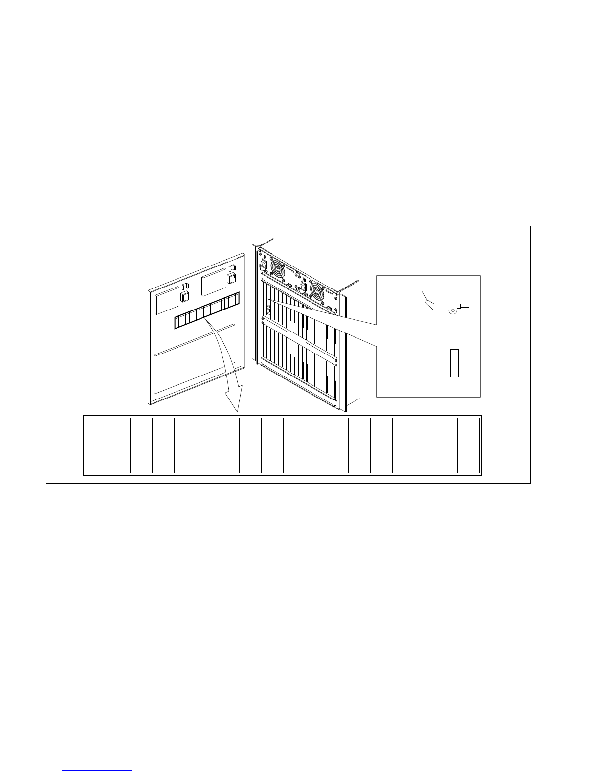
BKDS-7023LR
Page 8

4
DVS-7000AE IM
Contents
This manual is organized by following sections.
Section 1 Installation
This section describes the operating environment, power supply, connectors, input
and output signals of connectors, and example of system connection.
Section 2 Installation of DVS-7000A
This section describes the external dimensions and rack mounting.
Section 3 Installation of Control panel
This section describes the external dimensions, installation space, rack mounting and
replacement of key tops.
Section 4 Installation of Options
This section describes the installation of plug-in boards, combinations of optional
boards and installation of options.
Section 5 Confirmation in Installation
This section describes the switch settings on boards and LEDs description, Adjustment of secondary power supply voltage and adjustment of operation power for
fader lever.
Section 6 Initial Set-up of System
This section describes the operation and saving of set-up data, installation of program, set-up, saving set-up data to nonvolatile memory.
Page 9

DVS-7000AE IM
5
Related manuals
The following manuals are prepared for DVS-7000A.
The part numbers of these manuals as of February, 1999 describe.
..
..
. User’s Guide (Supplied with BZS-7020A)
This manual describes the application and operation of DVS-7000A.
..
..
. Operation Manual (Supplied with DVS-7000A)
This manual describes the overview, system configuration examples and specifications of
options.
..
..
. Maintenance Manual Part 1 (Supplied with DVS-7000A)
This manual describes the information for the periodic maintenance, and the
information for the service with predicated on the replacement of the principal
blocks and mounted circuit boards.
Part number : 3-201-864-01
..
..
. Maintenance Manual Part 2
The following manuals describe the detailed service information. For obtaining,
please contact your local Sony’s sale/service office.
Volume 1 (Block diagrams and Frame wirings)
Part number : 9-967-615-03
Supplement 4 Part number : 9-967-615-84
Volume 2
(Spare parts, Service overview and Replacement of main parts)
Part number : 9-967-616-03
Supplement 5 Part number : 9-967-616-85
Volume 3 (Semiconductor pin assignments)
Part number : 9-967-617-03
Supplement 3 Part number : 9-967-617-83
Volume 4 (Board layouts)
Part number : 9-967-618-03
Supplement 4 Part number : 9-967-618-84
Volume 5 (Schematic diagrams 1 A through I)
Part number : 9-967-624-03
Supplement 3 Part number : 9-967-624-83
Volume 6 (Schematic diagrams 2 K through Z)
Part number : 9-967-625-02
Supplement 4 Part number : 9-967-625-84
Page 10

Page 11

DVS-7000AE IM
1-1
1-2-3. Power Cord
w
The power cords are not supplied with DVS-7000A, the
control panels. Be sure to use the power cords that are
applicable to the places in the world.
n
The plug holder is not used for the control panels.
n
For the customer outside of the area as shown above,
please consult with local Sony’s sale/service office.
AC inlet
2
1
For the customer in the U.S.A. and Canada
Required Parts
1 Power Cord, 125 V 10 A (2.4 m) : 1-557-377-11
2 Plug Holder B (Black) : 2-990-242-01
2
AC inlet
1
For the customer in the United Kingdom
Required Parts
DK-2401 (EK)
1 Power Cord, 250 V 10 A (2.4 m)
2 Plug Holder B (Black) : 2-990-242-01
AC inlet
2
1
For the customer in the all European countries
except the United Kingdom
Required Parts
DK-2401 (AE)
1 Power Cord, 250 V 10 A (2.4 m)
2 Plug Holder B (Black) : 2-990-242-01
Section 1
Installation
1-1. Operating Environment
. Install the unit in a well ventilated place to prevent a
temperature rise in the unit. Never cover the ventilation
holes of the outer frame.
. Never install the unit near a heat source because the
environmental temperature during operation should be
5 dC to 40 dC.
1-2. Power Supply
1-2-1. Power Switch for Service
(Control panel)
w
The power switches for service of the control panels are
placed only in the unit.
When installing the unit, incorporate a readily accessible
disconnect device in the fixed wiring, so that the operator/
engineer power in case a fault should occur.
1-2-2. Power Specifications
Power requirements : 100 to 240 V AC ±10%
50/60 Hz
Current consumption
DVS-7000A : 7 to 3.5 A
BKDS-7011/7012 : 1.0 A (max.)
7021/7022/7023
7011R
7021R/7022R/7023R
7011LR
7021LR/7022LR/7023LR
m
As the inrush current at turn-on is the maximum 35 A, the
capacity of the AC power must be commensurate in it with
the inrush current of the maximum 35 A for the processor
and the control panel respectively. If the capacity of the
AC power is not the adequately large, the breaker of the
AC power at the supply side will operate or the unit will
abnormal operate.
Page 12

1-2
DVS-7000AE IM
1-3. Connectors
1-3. Connectors
When connecting cables to various connectors on the rear
panel at the time of installing, connecting or servicing,
connect the following connectors or their equivalents.
1. DVS-7000A
Connector function name Connector parts No. and
on rear panel name of cable
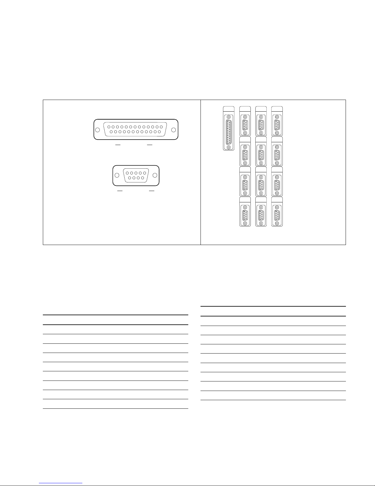
PANEL 1 D-sub 9-pin, Male
DME 1 to 4 Connector 9-pin, Male
SERIAL TALLY 1-560-651-00
(*1)
DSK Junction Shell 9-pin
TERMINAL 1-561-749-00
EDITOR A/REMOTE 1
EDITOR A/REMOTE 2
PANEL 2/REMOTE 3
GPI D-sub 25-pin, Male
Connector 25-pin, Male
1-560-904-11
(*1)
Junction Shell 25-pin
1-563-377-11
PRIMARY INPUTS 1 to 36 BNC Coaxial Connector Plug
DIRECT INPUT
CRK INPUTS 1 to 4
REF INPUT
REF OUTPUT
AUX BUS OUTPUTS 1 to 13
ME-1 to 3 OUTPUTS
PGM OUTPUTS 1 to 4
CLEAN OUTPUT
PST OUTPUT
EDIT PVW OUTPUT
MATRIX
(*3)
AC IN Main Power Supply Cable
(For the details of the cable,
refer to Section 1-2-3.)
2. BKDS Control Panel
(BKDS-70xx/70xxR/70xxLR)
Connector function name Connector parts No. and
on rear panel name of cable
SWITCHER D-sub 9-pin, Male
DSK Connector 9-pin,Male
DME 1-560-651-00
(*1)
TERMINAL 1 to 2 Junction Shell 9-pin
REMOTE 1 to 5 1-561-749-00
GPI D-sub 25-pin, Male
Connector 25-pin, Male
1-560-904-11
(*1)
Junction Shell 25-pin
1-563-377-11
AUX PANEL BVS Cable
(*2)
DISPLAY PANEL 1-574-993-11
OPTION PANEL
AC IN Main Power Supply Cable
(For the details of the cable,
refer to Section 1-2-3.)
(*1) : The following solderless contact must be used for the plug.
AWG #18 to #22:1-566-493-00
AWG #22 to #24:1-564-774-00
AWG #24 to #30:1-564-775-00
(*2) : The BVS cables are supplied with the models in the list below.
(*3) : Use the 9-pin BNC conversion cable supplied with DVS-7000A.
Model name DISPLAY AUX BUS OPTION TOTAL
PANEL PANEL PANEL
BKDS-701x 1 1
BKDS-701xR/ 1 1 2
701xLR
BKDS-702x 1 1 2
BKDS-702xR/
702xLR 1 1 1 3
Page 13
DVS-7000AE IM
1-3
1-4. Input and Output Signals of Connectors
1-4. Input and Output Signals of Connectors
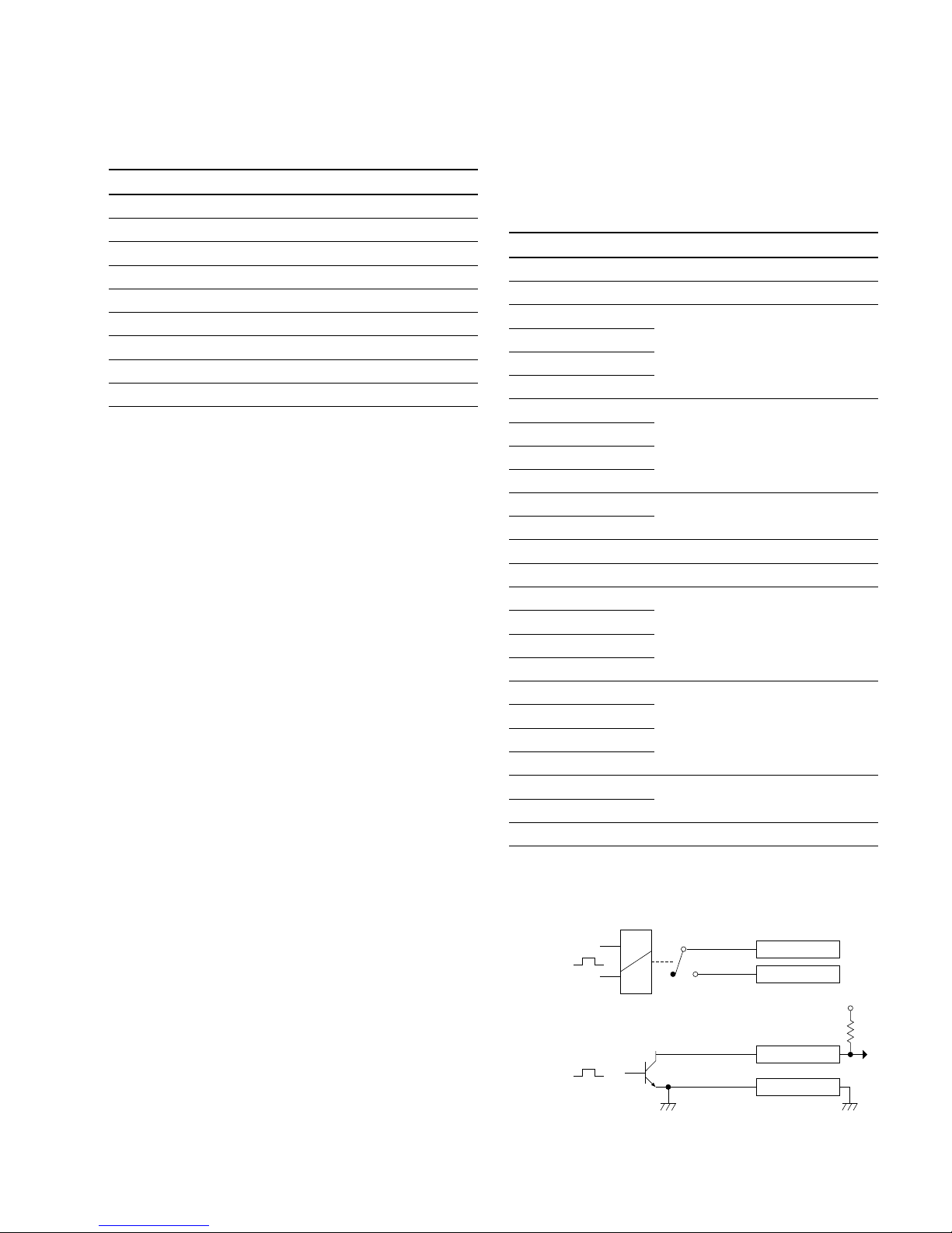
The input and output signals of the connectors on the rear panel are specified in the following table.
And refer to the following illustration for the pin positions of the connectors.
1-4-1. DVS-7000A
EXT VIEW
1
13
14
25
[D-SUB 25 PIN • FEMALE]
Rear panel
[D-SUB 9 PIN • FEMALE]
EXT VIEW
1
5
69
GPI
TERMINAL
DSK
MATRIX
SERIAL
TALLY
DME 2
DME 4
PANEL 1
DME 1
DME 3
PANEL 2
/REMOTE 3
EDITOR B
/REMOTE 2
EDITOR A
/REMOTE 1
m
(*1) <CONTROLLER> : Controlling device
(*2) <DEVICE> : Controlled device
PANEL 1 : RS-422A (D-sub 9-pin.Female)
<DEVICE>
(*2)
from Control panel BKDS-7011/7012/7021/
7022/7023 etc.
Pin No. Signal Name Function
1 GND Frame ground
2 CON TX-A Transmitted data (_)
3 CON RX-B Received data (+)
4 GND Common ground
5 VD-B Transmited VD signal (+)
6 GND Common ground
7 CON TX-B Transmitted data (+)
8 CON RX-A Received data (_)
9 VD-A Transmited VD signal (_)
PANEL 2/REMOTE 3 : RS-422A(D-sub 9-pin.Female)
<DEVICE>
(*2)
from Control panel
(*3)
Pin No. Signal Name Function
1 GND Frame ground
2 CON TX-A Transmitted data (_)
3 CON RX-B Received data (+)
4 GND Common ground
5 VD-B Transmited VD signal (+)
6 GND Common ground
7 CON TX-B Transmitted data (+)
8 CON RX-A Received data (_)
9 VD-A Transmited VD signal (_)
(*3) : Control Panel BKDS-2010 etc. (PANEL 2)
Keyer Remote Panel BKDS-7060 etc. (REMOTE 3)
Page 14

1-4
DVS-7000AE IM
1-4. Input and Output Signals of Connectors
SERIAL TALLY : RS-422A (D-sub 9-pin.Female)
n
For the SERIAL TALLY connector, refer to the Protocol
Manual of DVS-8000 Series.
Pin No. Signal Name Function
1 FG Frame ground
2 SERIAL TALLY RX-A Received data (_)
3 SERIAL TALLY TX-B Transmitted data (+)
4 GND Common ground
5 __
6 GND Common ground
7 SERIAL TALLY RX-B Received data (+)
8 SERIAL TALLY TX-A Transmitted data (_)
9 FG Frame Ground
DME 1 to 4 : RS-422A (D-sub 9-pin.Female)
<DEVICE>from Digital multi effects DME-3000/5000
etc.
Pin No. Signal Name Function
1 FG Frame ground
2 DME 1 to 4 TX-A Transmitted data (_)
3 DME 1 to 4 RX-B Received data (+)
4 GND Common ground
5 __
6 GND Common ground
7 DME 1 to 4 TX-B Transmitted data (+)
8 DME 1 to 4 RX-A Received data (_)
9 FG Frame Ground
DSK : RS-422A (D-sub 9-pin.Female)
<DEVICE>
(*2)
from DMK-7000
Pin No. Signal Name Function
1 FG Frame ground
2 DSK TX-A Transmitted data (_)
3 DSK RX-B Received data (+)
4 GND Common ground from
5 __
6 GND Common ground
7 DSK TX-B Transmitted data (+)
8 DSK RX-A Received data (_)
9 FG Frame Ground
MATRIX
(*4)
: (D-sub 9-pin.Female)
<DEVICE>
(*1)
to Routing switcher
Pin No. Signal Name Function
1 FG Frame ground
2 GND Ground
3 DATA Data
4 GND Ground
5 __
6 GND Ground
7 GND Ground
8 GND Ground
9 FG Frame Ground
(*4) : If connecting Sony’s Routing Switcher DVS-V6464B, use the 9-pin
BNC conversion cable supplied with DVS-7000A.
EDITOR A/REMOTE 1 : RS-422A (D-sub 9-pin.Female)
<DEVICE>
(*2)
from Editor
(*5)
Pin No. Signal Name Function
1 FG Frame ground
2 EDT A TX-A Transmitted data (_)
3 EDT A RX-B Received data (+)
4 GND Common ground
5 __
6 GND Common ground
7 EDT A TX-B Transmitted data (+)
8 EDT A RX-A Received data (_)
9 FG Frame Ground
(*5) : Editing control Unit BVE-9100 etc. (EDITOR A)
Digital Multi Effects DME-3000/5000 etc. (REMOTE 1)
EDITOR B/REMOTE 2 : RS-422A (D-sub 9-pin.Female)
<DEVICE>
(*2)
from Editor
(*6)
Pin No. Signal Name Function
1 FG Frame ground
2 EDT B TX-A Transmitted data (_)
3 EDT B RX-B Received data (+)
4 GND Common ground
5 __
6 GND Common ground
7 EDT B TX-B Transmitted data (+)
8 EDT B RX-A Received data (_)
9 FG Frame Ground
(*6) : Editing control Unit BVE-9100 etc. (EDITOR B)
Digital Multi Effects DME-3000/5000 etc. (REMOTE 2)
Page 15
DVS-7000AE IM
1-5
GPI : (D-sub 25-pin.Female)
INPUT x 8, TTL
OUTPUT x 4, relay contact 30 V 0.1 A (resistance load)
OUTPUT x 4, open collector 30 V rated voltage
GPI timing : Refer to User’s Guide
Pin No. Signal Name Function
1 GND Ground
2 GND Ground
3 GPI IN 2
4 GPI IN 4
General-purpose input
5 GPI IN 6
6 GPI IN 8
7 GPI OUT 1B
8 GPI OUT 2B
General-purpose relay output (B)
(*8)
9 GPI OUT 3B
10 GPI OUT 4B
11 GPI OUT 6
General-purpose open collector output
(*9)
12 GPI OUT 8
13 GPI OUT COM Ground for open collector output
14 GND Ground
15 GPI IN 1
16 GPI IN 3
General-purpose input
17 GPI IN 5
18 GPI IN 7
19 GPI OUT 1A
20 GPI OUT 2A
General-purpose relay output (A)
(*8)
21 GPI OUT 3A
22 GPI OUT 4A
23 GPI OUT 5
General-purpose open collector output
(*9)
24 GPI OUT 7
25 GPI OUT COM Ground for open collector output
n
A and B of same number constitute a pair of relay contacts.
TERMINAL : RS-232C (D-sub 9-pin.Female)
to Terminal
Pin No. Signal Name Function
1 DCD Data Carrier detect
(*7)
2 RXD Received data
3 TXD Transmitted data
4 DTR Data terminal ready
(*7)
5 GND Ground
6 DSR Data set ready
(*7)
7 RTS Request to send
8 CTS Clear to send
9 __
(*7) : Pins 1, 4 and 6 are short-circuited each other on the CN-1146 board.
1-4. Input and Output Signals of Connectors
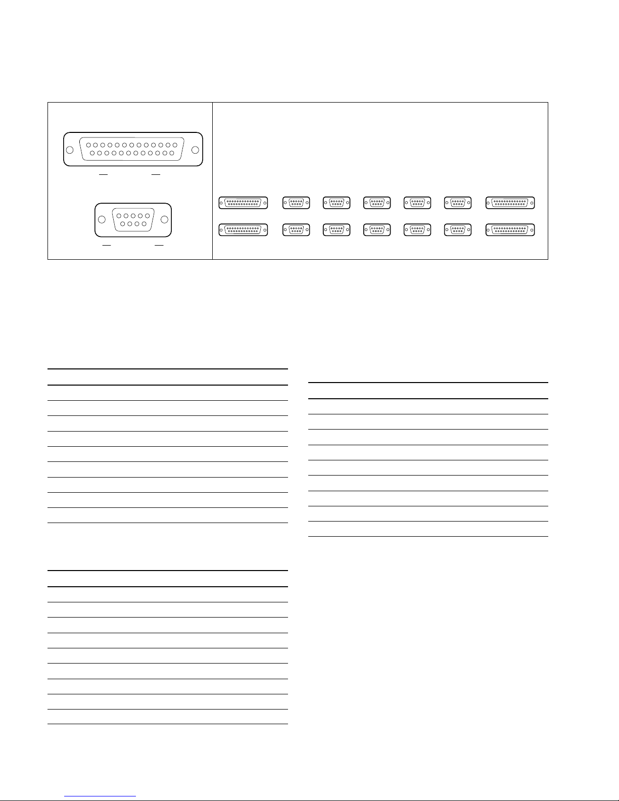
(*8) : <Relay>
GPI OUT x B
GPI OUT 5-8
GPI OUT COM
(*9) : <Open collector output>
x;1-4
+V
GPI OUT x A
Page 16
1-6
DVS-7000AE IM
EXT VIEW
1
13
14
25
1
13
14
25
1
13
14
25
[D-SUB 25 PIN • FEMALE]
Rear panel
GPI SWITCHER DSK DME TERMINAL1 TERMINAL2
AUX PANEL
OPTION PANEL REMOTE1 REMOTE2 REMOTE3 REMOTE4 REMOTE5
DISPLAY PANEL
[D-SUB 9 PIN • FEMALE]
EXT VIEW
1
5
69
1
5
69
1
5
69
1
5
69
1
5
69
1
5
69
1
13
14
25
1
13
14
25
1
5
69
1
5
69
1
5
69
1
5
69
1
5
69
1-4-2. Control Panel
m
(*1) <CONTROLLER> : Controlling device
1. Main Panel
SWITCHER : RS-422A (D-sub 9-pin.Female)
<CONTROLLER>
(*1)
to Processor DVS-7000A
Pin No. Signal Name Function
1 FG Frame ground
2 RX-A Received data (_)
3 TX-B Transmitted data (+)
4 GND Common ground
5 FIELD (+) Field signal input (+)
6 GND Common ground
7 RX-B Received data (+)
8 TX-A Transmitted data (_)
9 FIELD (_) Field signal input (_)
DSK : RS-422A (D-sub 9-pin.Female)
<CONTROLLER>
(*1)
to DMK-7000
Pin No. Signal Name Function
1 FG Frame ground
2 RX-A Received data (_)
3 TX-B Transmitted data (+)
4 GND Common ground
5 __
6 GND Common ground
7 RX-B Received data (+)
8 TX-A Transmitted data (_)
9 __
1-4. Input and Output Signals of Connectors
DME : RS-422A (D-sub 9-pin.Female)
<CONTROLLER>
(*1)
to Digital multi effects DME-3000/
7000 etc.
Pin No. Signal Name Function
1 FG Frame ground
2 RX-A Received data (_)
3 TX-B Transmitted data (+)
4 GND Common ground
5 __
6 GND Common ground
7 RX-B Received data (+)
8 TX-A Transmitted data (_)
9 __
Page 17

DVS-7000AE IM
1-7
REMOTE 1 : RS-422A (D-sub 9-pin.Female)
<CONTROLLER>
(*1)
to External Device
Pin No. Signal Name Function
1 FG Frame ground
2 RX-A Received data (_)
3 TX-B Transmitted data (+)
4 GND Common ground
5 __
6 GND Common ground
7 RX-B Received data (+)
8 TX-A Transmitted data (_)
9 __
REMOTE 2 to 5
(*2)
: RS-422A (D-sub 9-pin.Female)
<CONTROLLER>
(*1)
to External Device
Pin No. Signal Name Function
1 FG Frame ground
2 RX-A Received data (_)
3 TX-B Transmitted data (+)
4 GND Common ground
5 __
6 GND Common ground
7 RX-B Received data (+)
8 TX-A Transmitted data (_)
9 __
(*2) : BKDS-7001(Option:IF-523 board) is in need of using the REMOTE
from 1 to 4.
TERMINAL 1, 2 : RS-232C (D-sub 9-pin.Female)
to Terminal
Pin No. Signal Name Function
1 DCD Data carrier detect
(*3)
2 RXD Received data
3 TXD Transmitted data
4 DTR Data terminal ready
(*3)
5 GND Ground
6 DSR Data set ready
(*3)
7 RTS Request to send
(*4)
8 CTS Clear to send
(*4)
9 __
(*3) : Pins 1, 4 and 6 are short-circuited each other on the CN-1143 board.
(*4) : Pins 7 and 8 are short-circuitede each other on the CN-1143 board.
DISPLAY PANEL : (D-sub 25-pin.Female)
to Display panel
Pin No. Signal Name Function
1 GND Ground
2 +12 V Power supply +12 V
3 SCLK Serial clock for switch read and
LED light
4 GND Ground
5 WDT LED light data
6 IWLD Control signal for switch read and
LED light
7 GND Ground
8 ELCK EL display indicate clock
9 EL DATA 0 EL display indicate data
10 GND Ground
11 ELVD EL display vertical sync signal
12 GND Ground
13 GND Ground
14 +12 V Power supply +12 V
15 +12 V Power supply +12 V
16 BLANK LED light disable signal
17 GND Ground
18 SEQ Control signal for switch read and
LED light
19 RDT Switch read data
20 GND Ground
21 ELHD EL display horizontal sync signal
22 EL DATA 1 EL display indicate data 1
23 +12 V Power supply +12 V
24 +12 V Power supply +12 V
25 GND Ground
1-4. Input and Output Signals of Connectors
Page 18

1-8
DVS-7000AE IM
GPI : (D-sub 25-pin.Female)
INPUT x 8, TTL
OUTPUT x 4, relay contact 30 V 0.1 A (resistance load)
OUTPUT x 4, open collector 30 V rated voltage
GPI timing : Refer to User’s Guide
Pin No. Signal Name Function
1 GND Ground
2 GND Ground
3 GPI IN 2
4 GPI IN 4
General-purpose input
5 GPI IN 6
6 GPI IN 8
7 GPI OUT 1B
8 GPI OUT 2B
General-purpose relay output (B)
(*5)
9 GPI OUT 3B
10 GPI OUT 4B
11 GPI OUT 6
General-purpose open collector output
(*6)
12 GPI OUT 8
13 GND Ground
14 GND Ground
15 GPI IN 1
16 GPI IN 3
General-purpose input
17 GPI IN 5
18 GPI IN 7
19 GPI OUT 1A
20 GPI OUT 2A
General-purpose relay output (A)
(*5)
21 GPI OUT 3A
22 GPI OUT 4A
23 GPI OUT 5
General-purpose open collector output
(*6)
24 GPI OUT 7
25 GND Ground
n
A and B of same number constitute a pair of relay contacts.
AUX PANEL : (D-sub 25-pin.Female)
to AUX panel
Pin No. Signal Name Function
1 GND Ground
2 +12 V Power supply +12 V
3 SCLK Serial clock for switch read and
LED light
4 GND Ground
5 WDT LED light data
6 IWLD Control signal for switch read and
LED light
7 GND Ground
8 TCLK Serial clock for character display
9 TWDT Indicate data for character display
10 GND Ground
11 TBLANK Disable signal for character display
12 GND Ground
13 GND Ground
14 +12 V Power supply +12 V
15 +12 V Power supply +12 V
16 BLANK LED light disable signal
17 GND Ground
18 SEQ Control signal for switch read and
LED light
19 RDT Switch read data
20 GND Ground
21 TSEQ Control signal for character display
22 TQCLK Control signal for character display
23 +12 V Power supply +12 V
24 +12 V Power supply +12 V
25 GND Ground
1-4. Input and Output Signals of Connectors
(*5) : <Relay>
GPI OUT x B
GPI OUT 5-8
GPI OUT COM
(*6) : <Open collector output>
x;1-4
+V
GPI OUT x A
Page 19

DVS-7000AE IM
1-9
OPTION PANEL : (D-sub 25-pin.Female)
to Adaptor box (BKDS-7075)
Pin No. Signal Name Function
1 GND Ground
2 +12 V Power supply +12 V
3 SCLK Serial clock for switch read and
LED light
4 GND Ground
5 WDT LED light data
6 IWLD Control signal for switch read and
LED light
7 GND Ground
8 TCLK Serial clock for character display
9 TWDT Indicate data for character display
10 GND Ground
11 TBLANK Disable signal for character display
12 GND Ground
13 GND Ground
14 +12 V Power supply +12 V
15 +12 V Power supply +12 V
16 BLANK LED light disable signal
17 GND Ground
18 SEQ Control signal for switch read and
LED light
19 RDT Switch read data
20 GND Ground
21 TSEQ Control signal for character display
22 TQCLK Control signal for character display
23 +12 V Power supply +12 V
24 +12 V Power supply +12 V
25 GND Ground
n
This port is used for special-use-ready. Only when
connecting the control harness onto the CN8 of the connector on the CN-1143 board, this port is enable.
1-4. Input and Output Signals of Connectors
2. Display Panel
_ : (D-sub 25-pin.Female)
from Main panel
Pin No. Signal Name Function
1 GND Ground
2 +12 V Power supply +12 V
3 SCLK Serial colck for switch read and
LED light
4 GND Ground
5 WDT LED light data
6 IWLD Control signal for switch read and
LED light
7 GND Ground
8 ELCK LE display indicate clock
9 EL DATA 0 EL display indicate data 0
10 GND Ground
11 ELVD EL display vertical sync signal
12 GND Ground
13 GND Ground
14 +12 V Power supply +12 V
15 +12 V Power supply +12 V
16 BLANK LED light disable signal
17 GND Ground
18 SEQ Control signal for switch read and
LED light
19 RDT Switch read data
20 GND Ground
21 ELHD EL display horizontal sync signal
22 EL DATA 1 EL display indicate data 1
23 +12 V Power supply +12 V
24 +12 V Power supply +12 V
25 GND Ground
Page 20

1-10
DVS-7000AE IM
1-4. Input and Output Signals of Connectors
3. AUX Bus Panel
AUX PANEL :(D-sub 25-pin.Female)
from Main panel
Pin No. Signal Name Function
1 GND Ground
2 +12 V Power supply +12 V
3 SCLK Serial colck for switch read and
LED light
4 GND Ground
5 WDT LED light data
6 IWLD Control signal for switch read and
LED light
7 GND Ground
8 TCLK Serial clock for character display
9 TWDT Indicate data for character display
10 GND Ground
11 TBLANK Disable signal for character display
12 GND Ground
13 GND Ground
14 +12 V Power supply +12 V
15 +12 V Power supply +12 V
16 BLANK LED light disable signal
17 GND Ground
18 SEQ Control signal for switch read and
LED light
19 RDT Switch read data
20 GND Ground
21 TSEQ Control signal for character display
22 TQCLK Control signal for character display
23 +12 V Power supply +12 V
24 +12 V Power supply +12 V
25 GND Ground
Page 21

DVS-7000AE IM
1-11
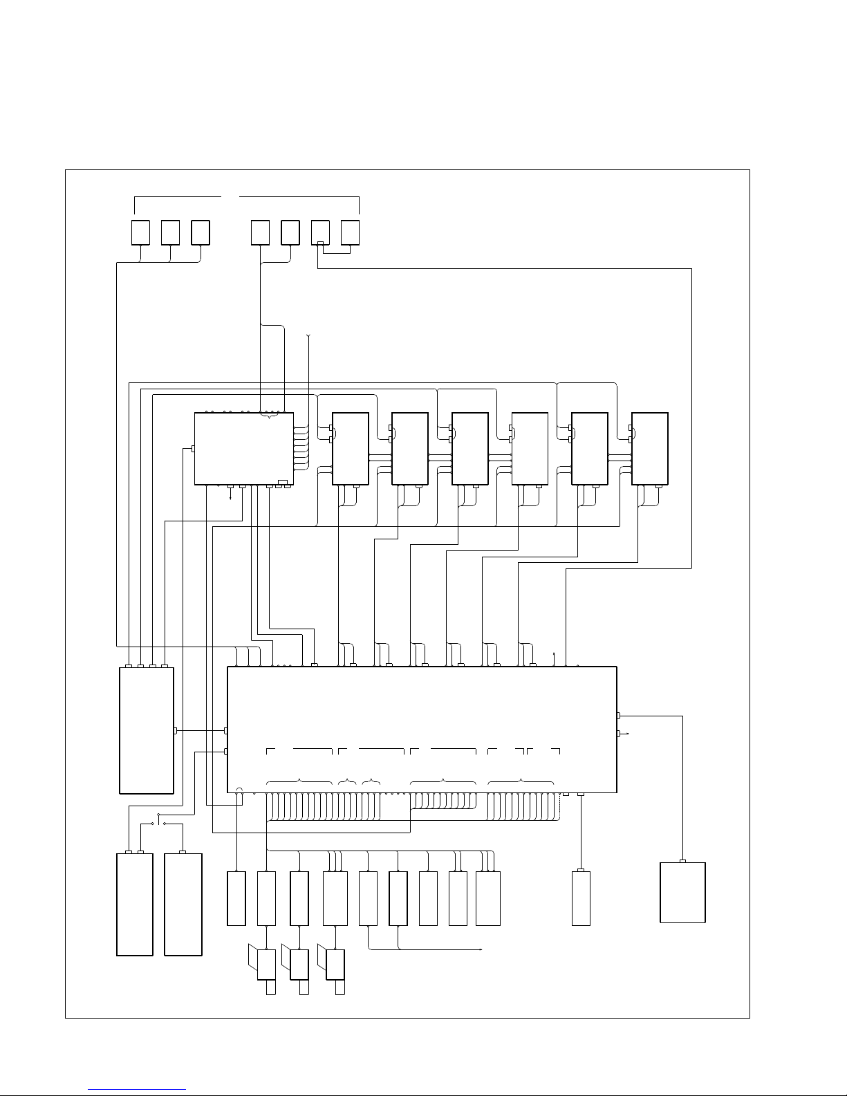
1-5. Examples of System Connection
1. D1 LIVE SWITCHER SYSTEM
1-5. Example of System Connection
SW'ER MAIN
MAIN PANEL
SUB PANEL
SG
DCU
CCU
DVR-2000
CG
PC
TALLY
1234567891011121314151617181920212223242526272829303132333435
36
D1 LIVE SW'ER
3ME+PP
SUPER
V/K
SOURCE
DCU
REC
SOURCE
DME1
DME2
DME3
DME4
DME5
DME6
DSK
DVW-500
BVW-75D
BVW-75
YUV
VKYUV
INTERFACE
UNIT
BKDS-7700
DVS-7000A
DMK-7000
DME-7000
DME-7000
DME-7000
DME-7000
DME-7000
DME-7000
ME1 PGM
ME2 PGM
ME3 PGM
PGM1
PGM2
PGM3
PGM4
PST
DSK
AUX1
AUX2
DME1
AUX3
AUX4
DME2
AUX5
AUX6
DME3
AUX7
AUX8
DME4
AUX9
AUX10
AUX11
AUX12
AUX13
EDIT PVW
DIRECT IN
TALLY
SERIAL
GPI
TERMINAL
MATRIX
CRK IN
x2
x2
INPUTS
COMPONENT
ANALOG
INPUTS
COMPONENT
ANALOG
Y1U1V1S1Y2U2V2S2Y3U3V3
S3
x12
DME V/K
INPUTS
DIGITAL
x4
SUPER V/K
x4
VTR
INPUTS
DIGITAL
x12
CAMERA
INPUTS
DIGITAL
REF OUT
REF IN
1
PANEL
REMOTE3
REMOTE2
DME
DSK
SW'ER
CONTROL
OUT1
BKDS-70xx/70xxR/70xxLR
BKDS-7060
BKDS-2010
PANEL B DSK1
PGM
PVW
DSK2
PGM
PVW
DSK3
PGM
PVW
DSK4
PGMSW ER
PST
PGM
PANEL A
TALLY/GP1
REF OUT
REF IN
OUT
EDITOR
IN
K4V4K3V3K2V2K1V1
MONITOR
ME1
ME2
ME3
PVW
DSK
DSK
PGM
VE
WFM
SW'ER
K
V
VKVKZ
SW'ER PANEL
DME PANEL
VKZ
DME PANEL
SW'ER PANEL
KV
V
K
SW'ER
DME PANEL
SW'ER PANEL
SW'ER
K
V
VKVKZ
VKZ
VKZ
VKZ
DME PANEL
SW'ER PANEL
SW'ER
K
V
VK
DME PANEL
SW'ER PANEL
SW'ER
K
V
VKVKZ
DME PANEL
SW'ER PANEL
VKZ
SW'ER
K
V
VK
PVW
EDITOR B
/REMOTE 2
EDIDOR A
/REMOTE 1
PANEL 2
/REMOTE 3
KEYER REMOTE
CONTROL PANEL
Y4/V4/U4/S4
CONTROL
OUT2
Page 22
1-12
DVS-7000AE IM
2. D2 LIVE SWITCHER SYSTEM
1-5. Example of System Connection
MAIN PANEL
SUB PANEL
V
K
SW'ER
VKZ
DME PANEL
SW'ER PANEL
VK
SG
CCU
CG
BVW75
PC
123456789101112131415161718192021222324252627282930313233343536Y1U1V1S1Y2U2V2S2Y3U3V3
S3
3ME+PP
MONITOR
SUPER
V/K
SOURCE
REC
SOURCE
DME1
DME2
DME3
DME4
DME5
DME6
CCU
CCU
DVR-20
D2 LIVE SW'ER
DSK
YUV
DVR-28
BVW-D265
VKYUV
V1 K1 V2 K2 V3 K3 V4 K4
DVS-7000A
DMK-7000
DME-7000
DME-7000
DME-7000
DME-7000
DME-7000
DME-7000
CONTROL
OUT1
BKDS-7060
BKDS-2010
SW'ER
SW'ER
DSK
REMOTE3
REMOTE2
DME
ME1 PGM
ME2 PGM
ME3 PGM
PGM1
PGM2
PGM3
PGM4
PST
DSK
AUX1
AUX2
DME1
AUX3
AUX4
DME2
AUX5
AUX6
DME3
AUX8
AUX7
DME4
AUX9
AUX10
AUX11
AUX12
AUX13
EDIT PVW
DIRECT IN
GPI
SERIAL
TALLY
TERMINAL
MATRIX
Y4/U4/V4/S4
x2
CRK IN
x2
x12
DME V/K
INPUTS
COMPONENT
ANALOG
INPUTS
COMPONENT
ANALOG
INPUTS
DIGITAL
INPUTS
DIGITAL
x4
SUPER V/K
x4
VTR
REF OUT
REF IN
1
PANEL
ANALOG
COMPOSITE
INPUTS
CAMERA
x12
REF IN
REF OUT
TALLY/GDI
PANEL A
PGM
PST
SW'ER
OUT
EDITOR
IN
DSK1
PGM
PVW
DSK2
PGM
PVW
DSK3
PGM
PVW
DSK4
PGM
PANEL B
DME PANEL
SW'ER PANEL
SW'ER
K
V
VKVKZ
DME PANEL
SW'ER PANEL
KZKVV
V
K
SW'ER
KZV
SW'ER
K
V
VK
SW'ER PANEL
DME PANEL
SW'ER
K
V
VKVKZ
SW'ER PANEL
DME PANEL
KZV
VKZ
KZV
SW'ER
K
V
VK
SW'ER PANEL
DME PANEL
PVW
ME1
ME2
ME3
PVW
DSK
DSK
PGM
VE
WFM
EDITOR A
EDITOR B
/REMOTE 1
/REMOTE 2
PANEL 2
/REMOTE 3
CONTROL PANEL
KEYER REMOTE
CONTROL
OUT2
BKDS-70xx/70xxR/70xxLR
TALLY
INTERFACE
UNIT
BKDS-7700
Page 23
DVS-7000AE IM
2-1
Section 2
Installation of DVS-7000A
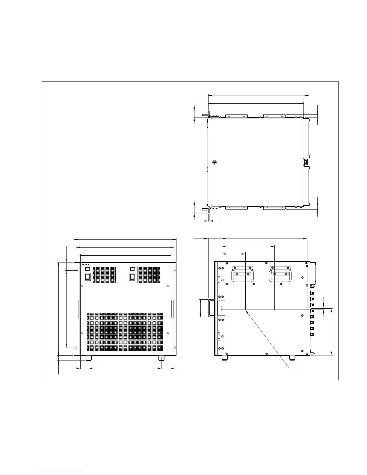
2-1. External Dimensions
A B
482
424
465
368.3
443 (10 UNIT)
23.5
40 40
37.35
13
221.5
111.1
28.5
250.8
403.2
8-M4
37.7
5.5
2929
13
13
477.8
452
Unit : mm
88
Page 24

2-2
DVS-7000AE IM
2-2. Rack Mounting
2-2. Rack Mounting
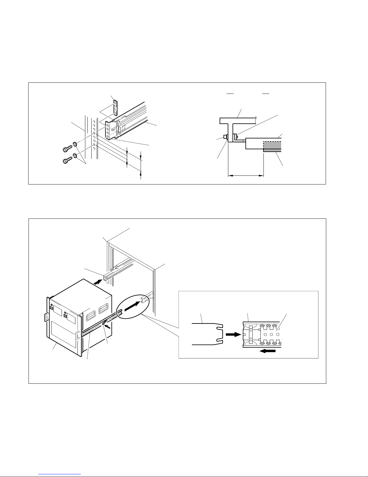
DVS-7000A can be mounted in a 19-inch standard rack. Be sure to use the optional rack mount rail
RMM-18DV.
Required Parts
. Rack mount rail (RMM-18DV)
. Screw for plate nut (long) installing (B4 x 8) : 8pcs
. Screw for rack mounting (RK5 x 16) : 4pcs
. Ornamental washer for rack mounting : 4pcs
(Sony part number : 2-297-913-01)
c
(1) If DVS-7000A is mounted in the 19-inch standard rack, it is recommended to install a ventilation fan
to prevent a temperature rise in the rack. Make sure that all the units in the rack should be operated
within the temperature range of 10 dC to 35 dC.
(2) Be sure to use the recommended rail when rack mounting. The unit cannot be installed completely to
a rack by rack angles alone.
(3) It is recommended to fix the rack to the floor with bolts. When the unit is pulled out from the rack,
this will prevent its fall.
(4) An installation manual is supplied with the rack mount rail RMM-18DV. However follow the
instructions in this manual. Because the rack mounting procedures of DVS-7000A differ somewhat
from the procedures explained in RMM-18DV installation manual.
(5) Be sure to mount in the rack with two-person or more.
Page 25

DVS-7000AE IM
2-3
Brackets
Plate nut (Long)
Outer member1
B4 x 8
B4 x 8
B4 x 8
B4 x 8
Outer member stopper
(Used for fixing the outer member2.)
(Fig. 3)
Plate nut (Long)
Outer member2
2-2. Rack Mounting
Procedures
(1) Pull out the inner member while pressing the stopper of the rack mount rail RMM-18DV. (Fig. 1)
(2) Secure the inner member to the unit by the sixteen screws (B4 x 8) supplied with DVS-7000A.
Remove the feet of the unit as required. (Fig. 2)
(3) Secure the bracket to the outer member 1 by the preparated eight screws (B4 x 8). (Fig. 3)
To see the screw hole of the outer member 1, move the outer member 1 back-and-forth.
DVS-7000A
Feet
B4 x 8
B4 x 8
Inner member
Inner member
Inner member
Stopper
Outer member1
(Fig. 2)(Fig. 1)
Page 26
2-4
DVS-7000AE IM
Bracket
Rack
Outer member
C4 x 12
W4
44.45
12.7
C4 x 12
W4
Outer member1
Bracket
Rack
TOP VIEW
Spec
50
_0
Plate nut (Short)
+5
(Fig. 4)
Plate nut (Short)
2-2. Rack Mounting
(4) Temporarily secure the bracket to the outer member assembly 1 to both sides of the rack by the
eight screws (C4 x 12) and the eight washers (W4) supplied with RMM-18DV. Adjust the installation position of the outer member to meet the specification shown in the figure. After the adjustment,
tighten the screws (B4 x 8) temporarily secured in the step (3). (Fig. 4)
(5) Install the unit in the rack while releasing the stopper of the inner member.
(6) After confirming that the unit can be moved smoothly, tighten the screws (C4 x 12) temporarily
secured in the step (4). (Fig. 5)
Outer member2
Stopper
Rack
DVS-7000A
Inner member
Inner member Slide bearing
. When housing the set, shift the slide bearing as illustrated.
Outer member2
(Fig. 5)
Page 27

DVS-7000AE IM
2-5
221.5
443
Distance to slide rail center
Set height when mounted in rack
30
Unit : mm
Maximum moving distance
569
Handle height
2-2. Rack Mounting
(7) After installing the unit in the rack, secure the unit to the rack by the prepared four screws (RK5 x
16) and the four ornamental washers. (Fig. 6)
. When DVS-7000A is mounted in a rack, the maximum traveling distance is illustrated below.
RK5 x 16
RK5 x 16
RK5 x 16
RK5 x 16
Ornamental washer
Ornamental washer
Rack
Rack
––– TOP VIEW–––
Rack angle
DVS-7000A
Bracket
Outer member
(Fig. 6)
RK5 x 16
Page 28

Page 29
DVS-7000AE IM
3-1
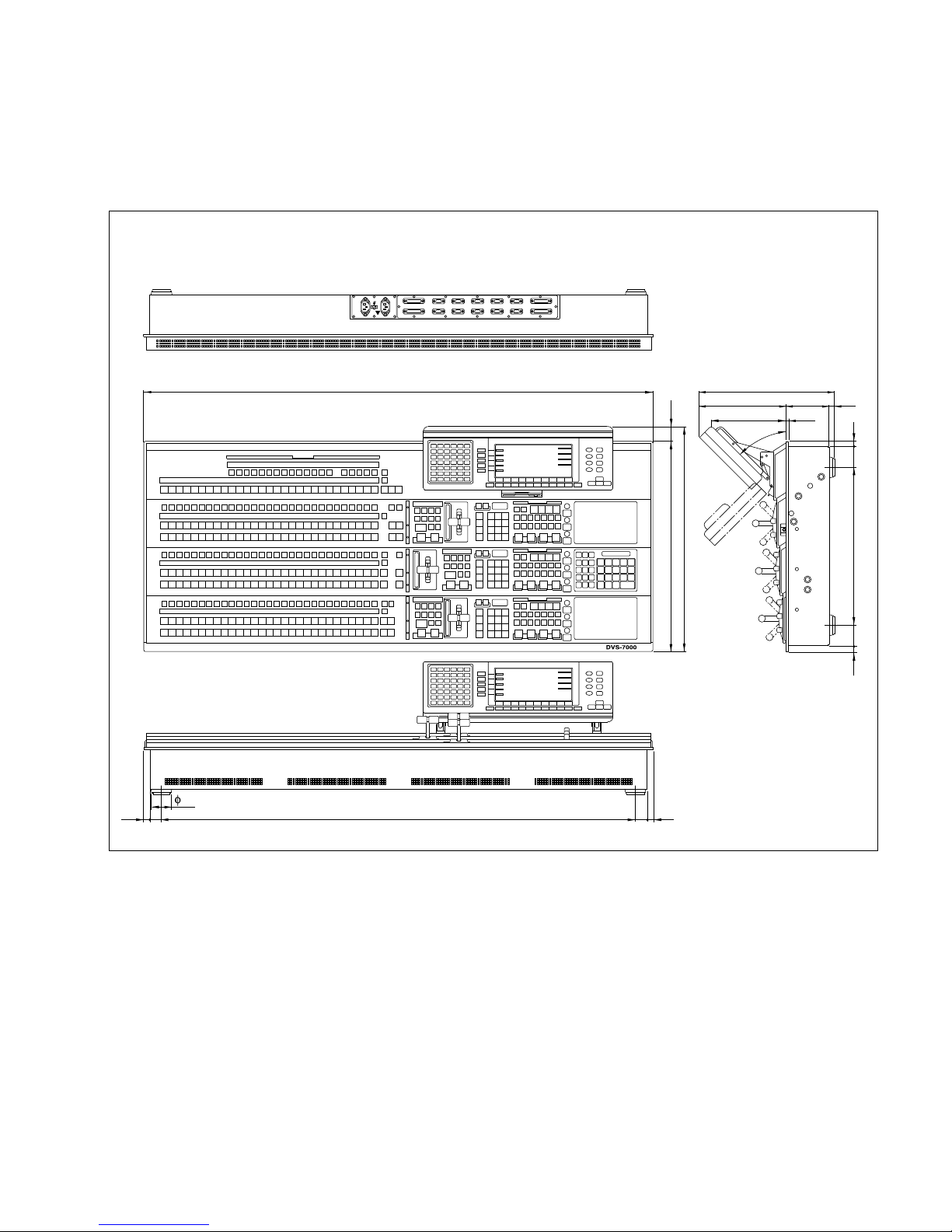
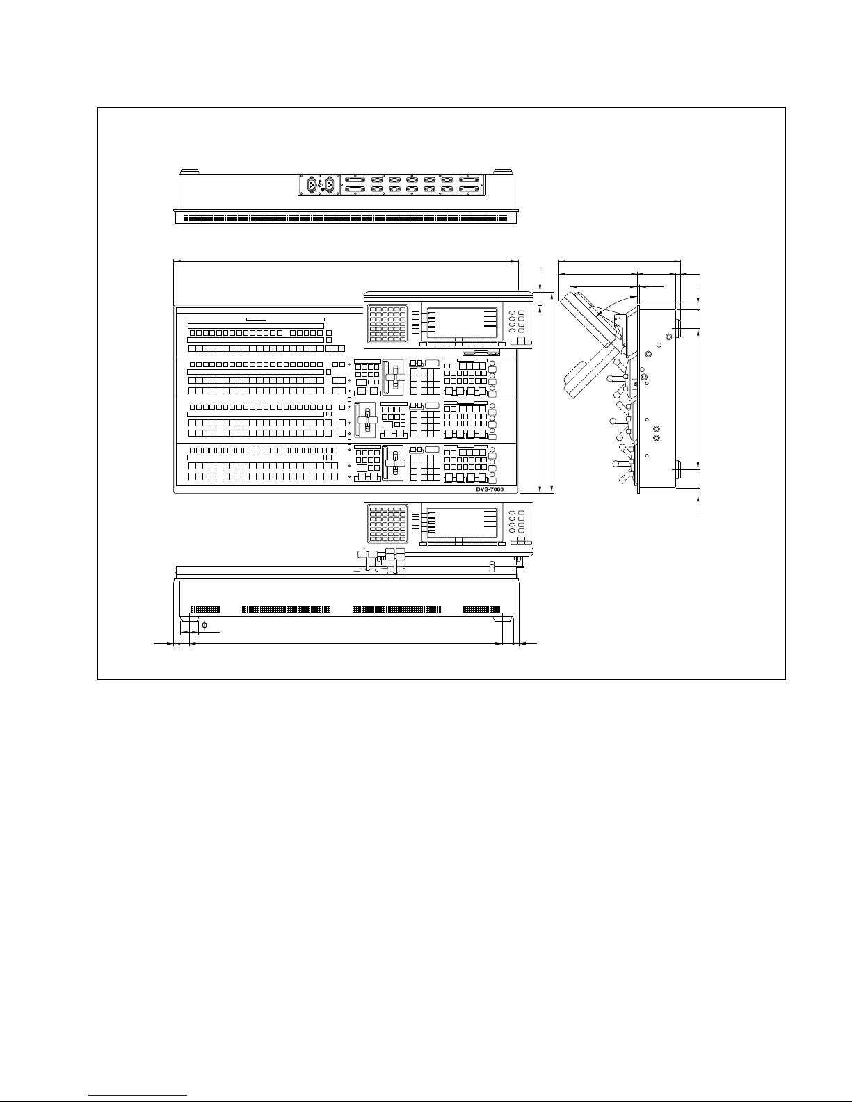
3-1. External Dimensions
* The above figure shows the BKDS-7011.
Section 3
Installation of Control Panel
Main Panel
BKDS-7011/7012
1290
15
30
1200
30
15
49
230
199 7.2
45˚
350
110 10
Unit : mm
572
532
(
40
)
(
51
)
15 51 15
400
Page 30
3-2
DVS-7000AE IM
3-1. External Dimensions
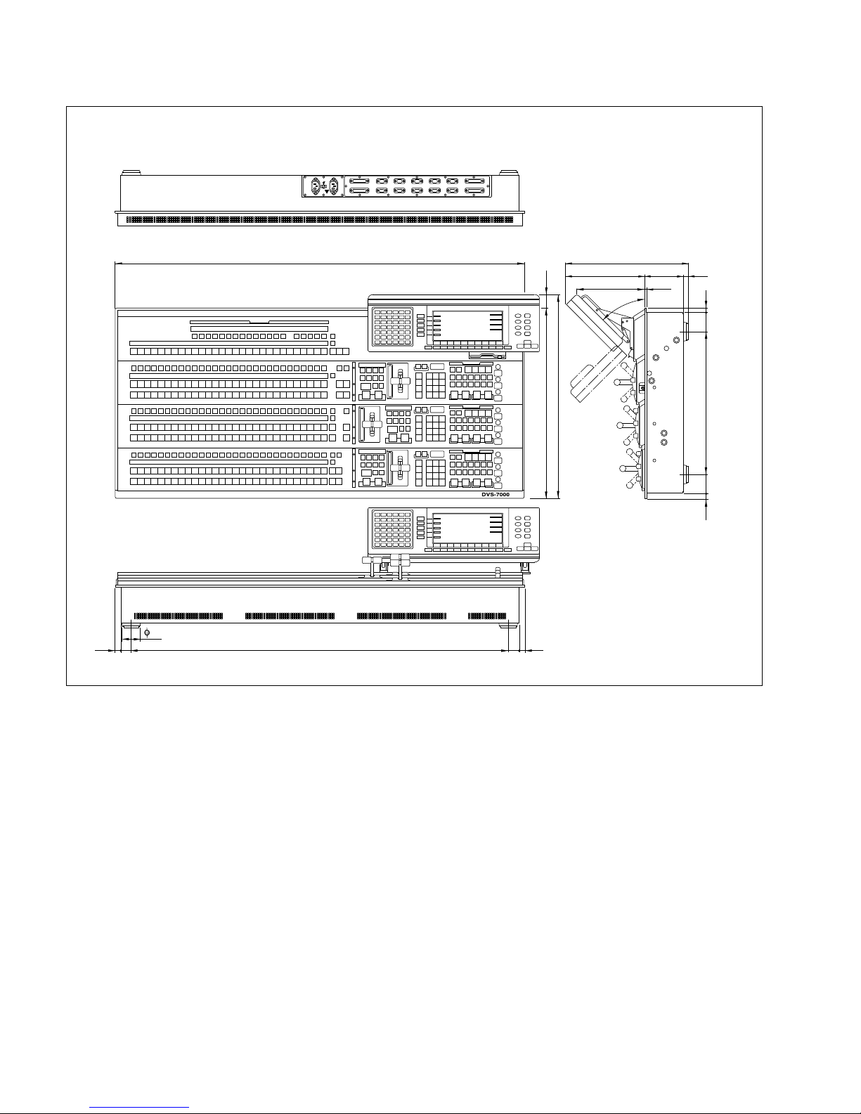
Main Panel
BKDS-7011R
1142
15
30
1052
30
15
49
230
199 7.2
45˚
350
110 10
Unit : mm
572
532
(
40
)
(
51
)
15 51 15
400
Page 31
DVS-7000AE IM
3-3
3-1. External Dimensions
Main Panel
BKDS-7011LR
971
15
30
881
30
15
49
230
199 7.2
45˚
350
110 10
Unit : mm
572
532
(
40
)
(
51
)
15 51 15
400
Page 32
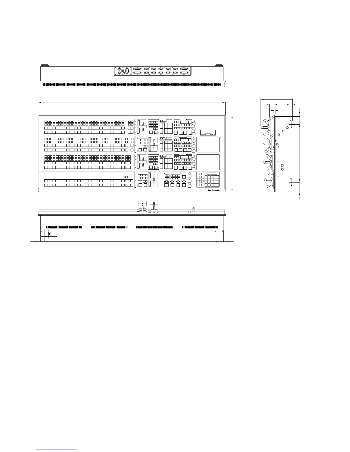
3-4
DVS-7000AE IM
3-1. External Dimensions
Main Panel
BKDS-7021/7022/7023
* The above figure shows the BKDS-7021.
1290
15
30
1200
30
15
49
110
7.2
10
32
215
Unit : mm
532
40015
(
51
)
1551
Page 33
DVS-7000AE IM
3-5
3-1. External Dimensions
Main Panel
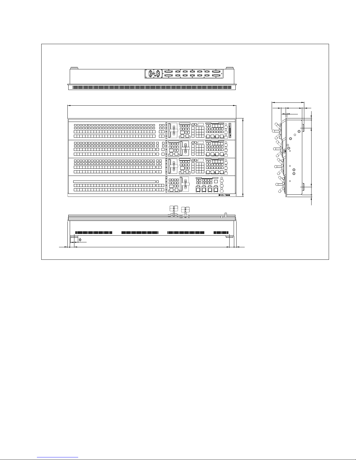
BKDS-7021R/7022R/7023R
* The above figure shows the BKDS-7021R.
1142
15
30
1052
30
15
49
110
7.2
10
32
215
Unit : mm
532
40015
(
51
)
1551
Page 34
3-6
DVS-7000AE IM
3-1. External Dimensions
Main Panel
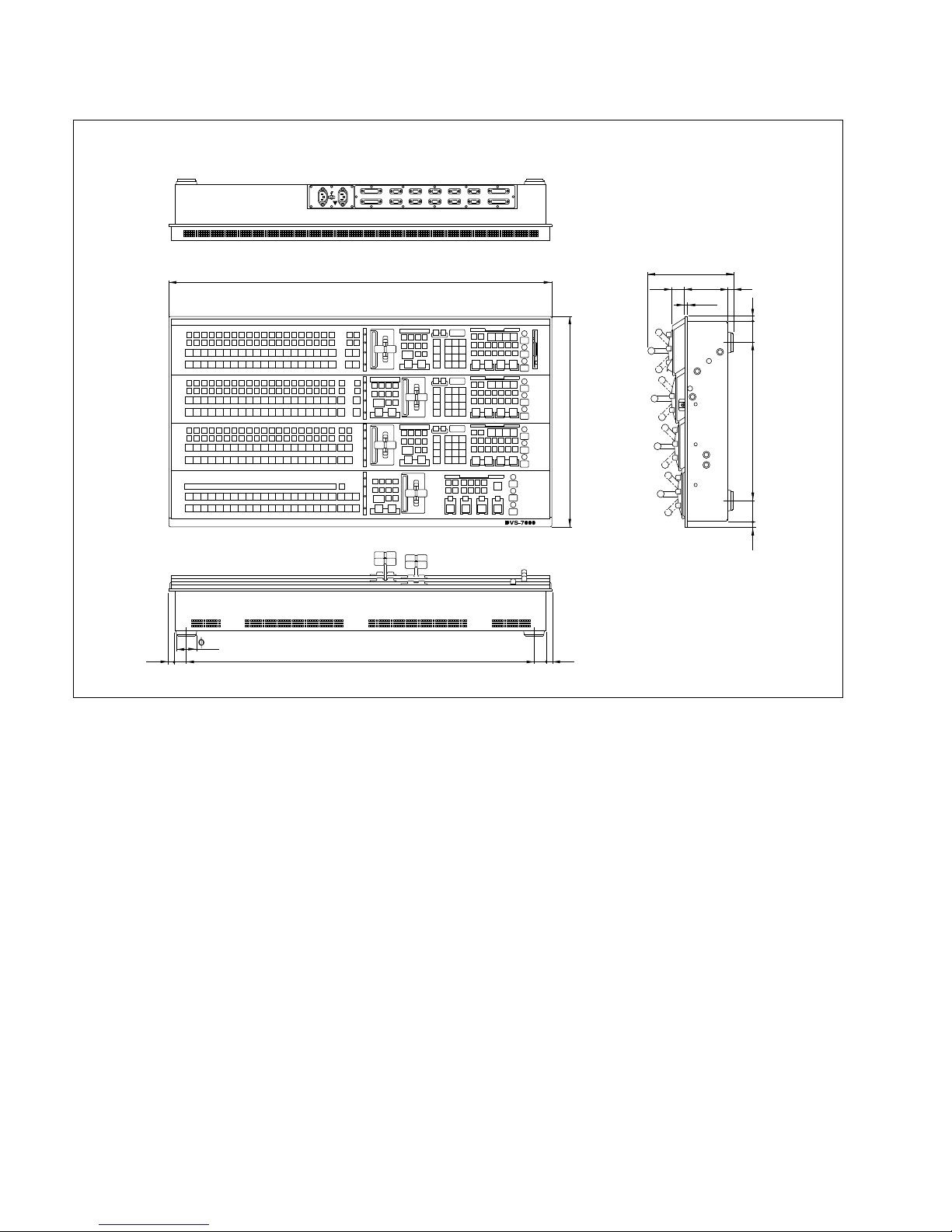
BKDS-7021LR/7022LR/7023LR
* The above figure shows the BKDS-7021LR.
971
15
30
881
30
15
49
110
7.2
10
32
215
Unit : mm
532
40015
(
51
)
1551
Page 35
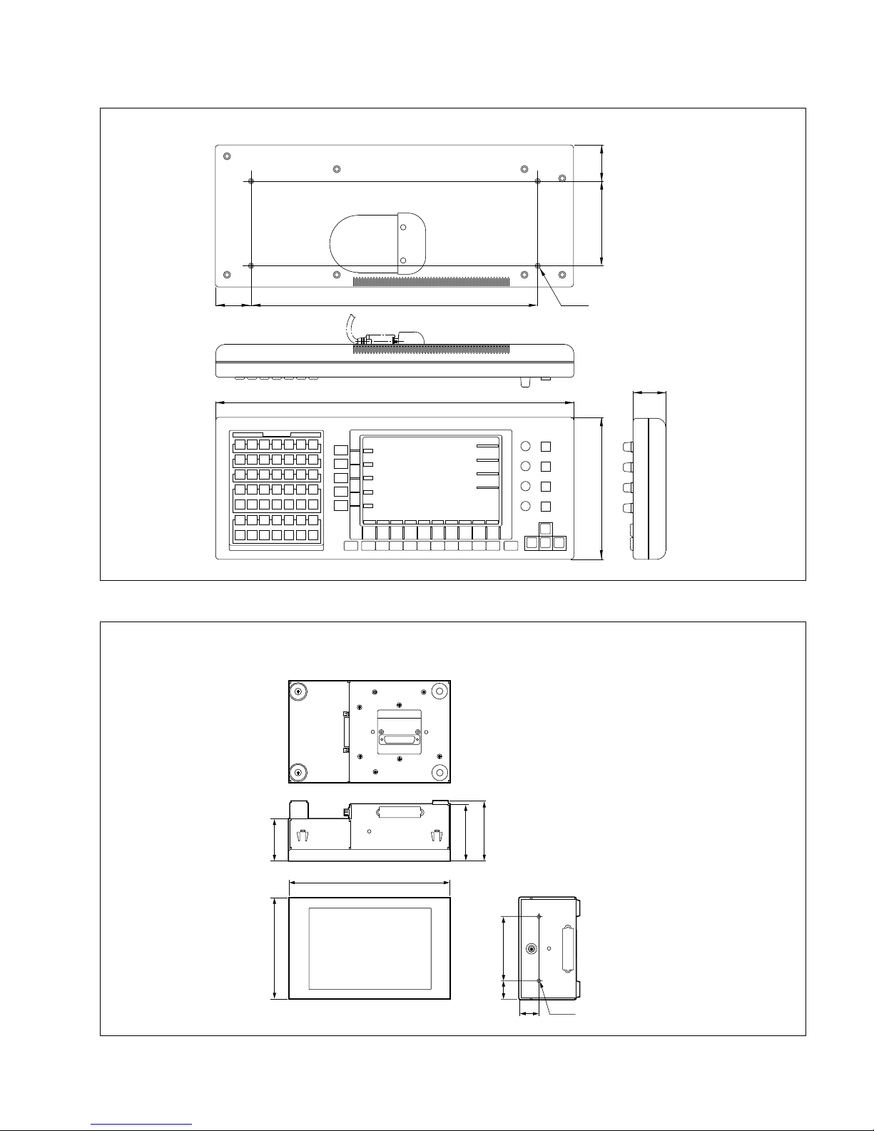
DVS-7000AE IM
3-7
499
197
45
400
117.7
4-M4
Unit : mm
49.5
50.8
3-1. External Dimensions
Display Panel
BKDS-7075
(BKDS-7011R/7021R/7022R/7023R/7011LR/7021LR/7022LR/7023LR)
132
55
24
26
2-M4
74
78.5
212
84
Unit : mm
Page 36
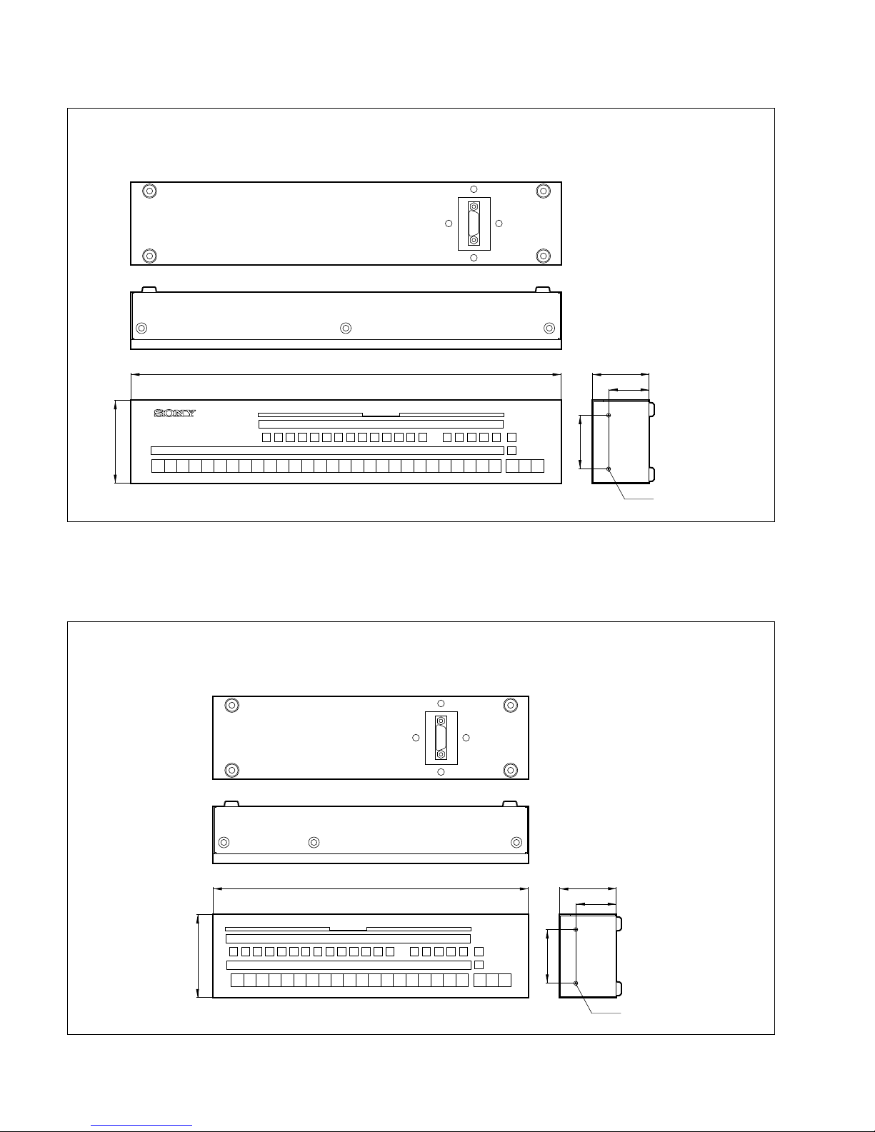
3-8
DVS-7000AE IM
680 90
64
132
84
2-M4
Unit : mm
3-1. External Dimensions
AUX Bus Panel
BKDS-7021/7022/7023/7021R/7022R/7023R
AUX Bus Panel
BKDS-7021LR/7022LR/7023LR
509 90
64
132
84
2-M4
Unit : mm
Page 37
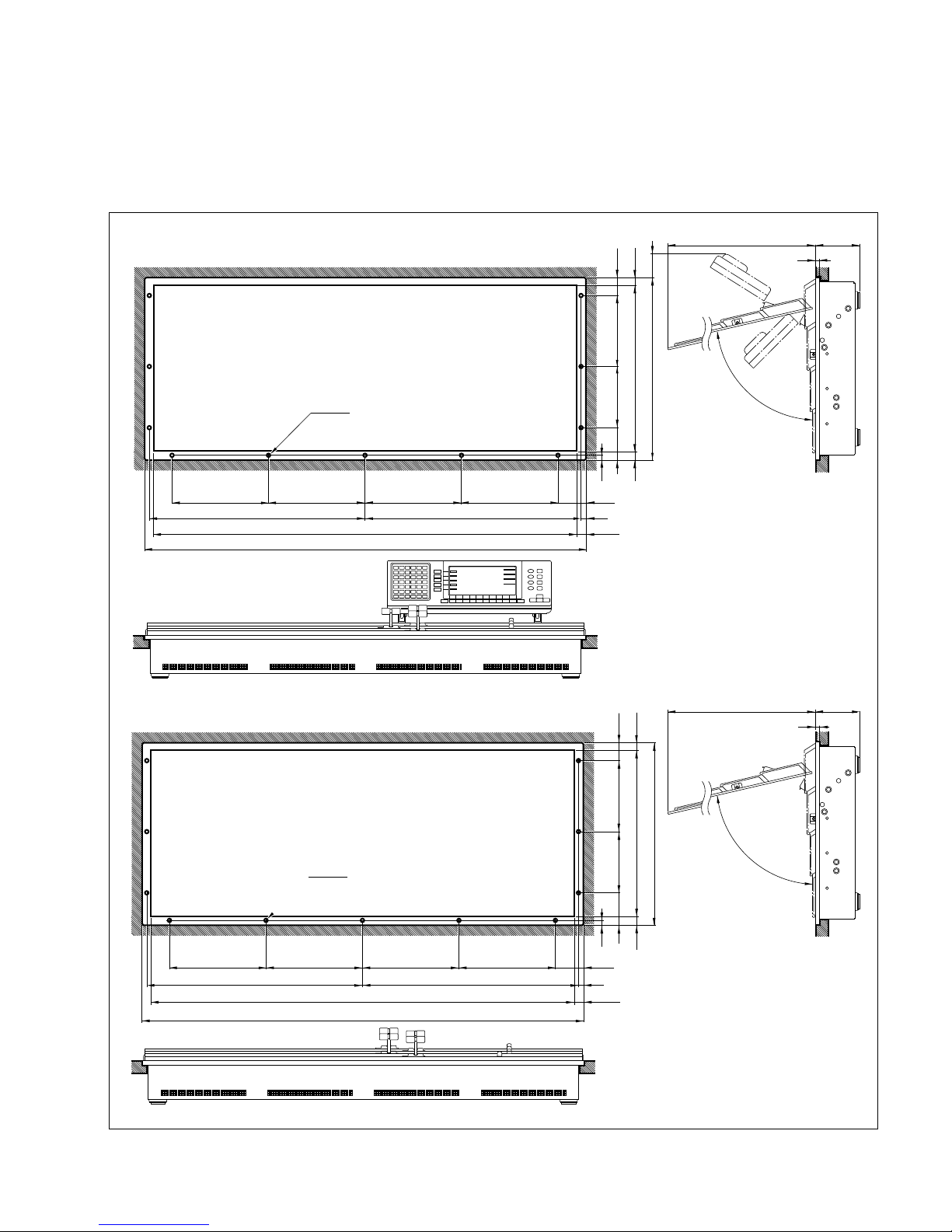
DVS-7000AE IM
3-9
1294
1265
300
300
638
638
300
300
(47)
14.5
6
119517
11-M4
Approx.73˚
Hole
9
9
14
186 216
508
536 40
(
52
)
(
14
)
When installing BKDS-7011/7012
in the console, make a hole on the
console for the connecting cable
between main panel and display
panel.
* :
1294
1265
300300
638
638
300
300
(47)
9
14.5
6
119517
11-M4
Unit : mm
9
14
18682 216
508
536
(
52
)
(
14
)
BKDS-7021/7022/7023
BKDS-7011/7012
Approx.73˚
Hole
3-2. Installation Space
3-2. Installation Space
Control panel can be installed in the console by drilling holes in the console in the locations specified
below.
BKDS-7021/7022/7023
BKDS-7011/7012
Page 38

3-10
DVS-7000AE IM
1146
1117
260
564
564
(53)
14.5
6
119517
11-M4
Approx.73˚
Hole
9
9
14
186 216
508
536 40
(
52
)
(
14
)
When installing BKDS-7011R
in the console, make a hole on the
console for the connecting cable
between main panel and display
panel.
* :
1146
1117
260
564
564
(53)
9
14.5
6
119517
11-M4
Unit : mm
9
14
18682 216
508
536
(
52
)
(
14
)
BKDS-7021R/7022R/7023R
BKDS-7011R/7012R
Approx.73˚
Hole
260260260
260260 260
3-2. Installation Space
BKDS-7011R
BKDS-7021R/7022R/7023R
Page 39
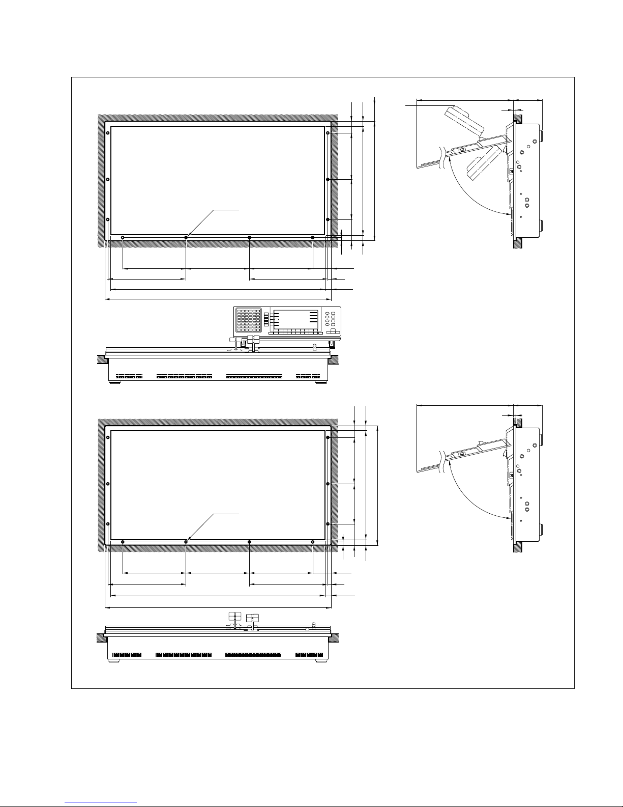
DVS-7000AE IM
3-11
975
946
290
333.5
(
52.5
)
14.5
6
119517
11-M4
Approx.73˚
Hole
9
9
14
186 216
508
536 40
(
52
)
(
14
)
BWhen installing BKDS-7011LR
in the console, make a hole on the
console for the connecting cable
between main panel and display panel.
*
975
946
290
333.5
333.5
(
52.5
)
9
14.5
6
119517
11-M4
Unit : mm
9
14
18682 216
508
536
(
52
)
(
14
)
-7021LR/7022LR/7023LR
-7011LR/7012LR
Approx.73˚
Hole
290290
290 290
333.5
:
3-2. Installation Space
BKDS-7011LR
BKDS-7021LR/7022LR/7023LR
Page 40
3-12
DVS-7000AE IM
BKDS-70xx/70xxR/70xxLR
Console
B4 x 6
B4 x 6
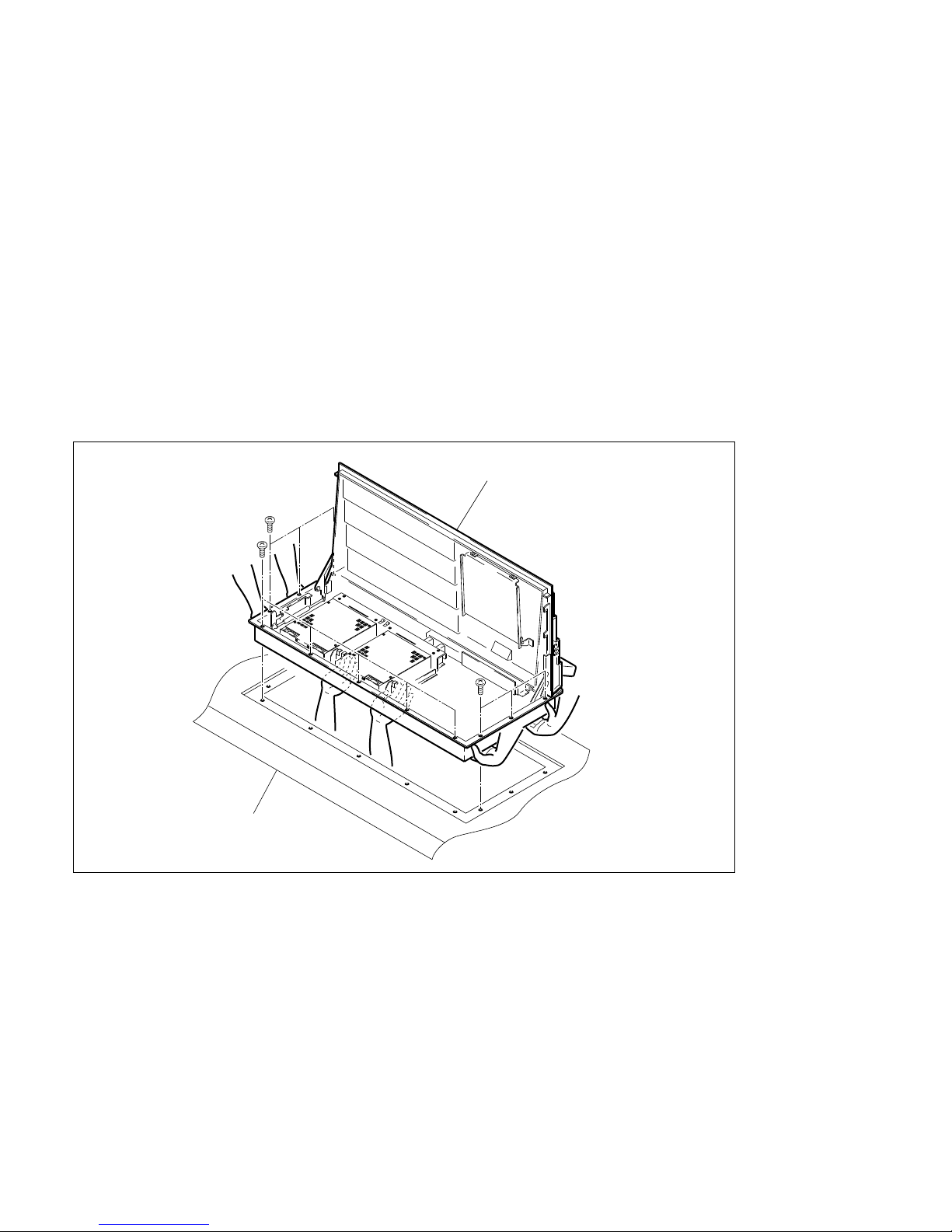
3-3. Installation of MAIN PANEL
c
(1) Be sure to install the main panel to the rack with three-person or more.
(2) Be sure to install the panel in the following procedures.
Prepared Part
. Screws (B4 x 6)
BKDS-70xx/70xxR : 11 pcs
BKDS-70xxLR : 10 pcs
(1) Lift the main panel with two-person or more. Then install the main panel to console while supporting
under the main panel with the other one person.
(2) Open the main panel. (Refer to section “4-4-1. Opening and Closing of Panel”.)
(3) Secure the main panel to the console by the prepared screws (B4 x 6).
3-3. Installation of MAIN PANEL
Page 41
DVS-7000AE IM
3-13
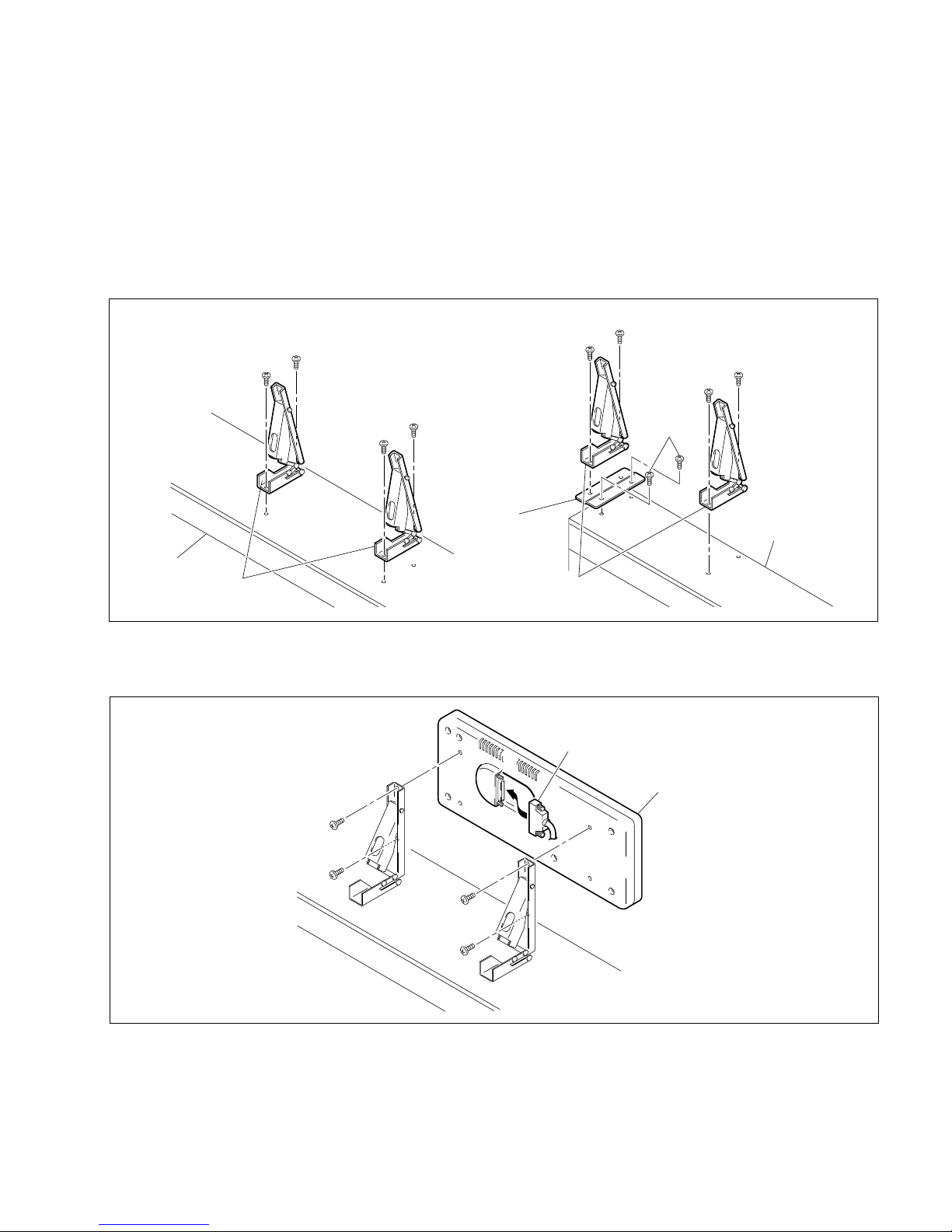
3-4. Installation of DISPLAY PANEL
3-4. Installation of DISPLAY PANEL
<BKDS-701x, 701xR and 701xLR>
(1) Only BKDS-701xR and 701xLR, secure the EL unit bracket to BKDS-701x, 701xR and 701xLR by
the two screws (B4 x 6) supplied with BKDS-701x, 701xR and 701xLR.
(2) Secure the EL table assembly to BKDS-701x, 701xR and 701xLR by the four screws (B4 x 6)
supplied with BKDS-701x, 701xR and 701xLR.
(3) Secure the DISPLAY PANEL to the EL unit assembly by the four screws (B4 x 6) supplied with
BKDS-701x, 701xR and 701xLR.
<BKDS-702x, 702xR and 702xLR>
Secure to the console by the four screws (M4).
Display panel
Cable
B4 x 6
B4 x 6
BKDS-7011/7012
EL table assy
B4 x 6
B4 x 6
B4 x 6
B4 x 6
BKDS-7011/7012
BKDS-7011R/7011LR
EL table assy
EL unit bracket
BKDS-7011R/7011LR
B4 x 6
B4 x 6
B4 x 6
B4 x 6
B4 x 6
Page 42
3-14
DVS-7000AE IM
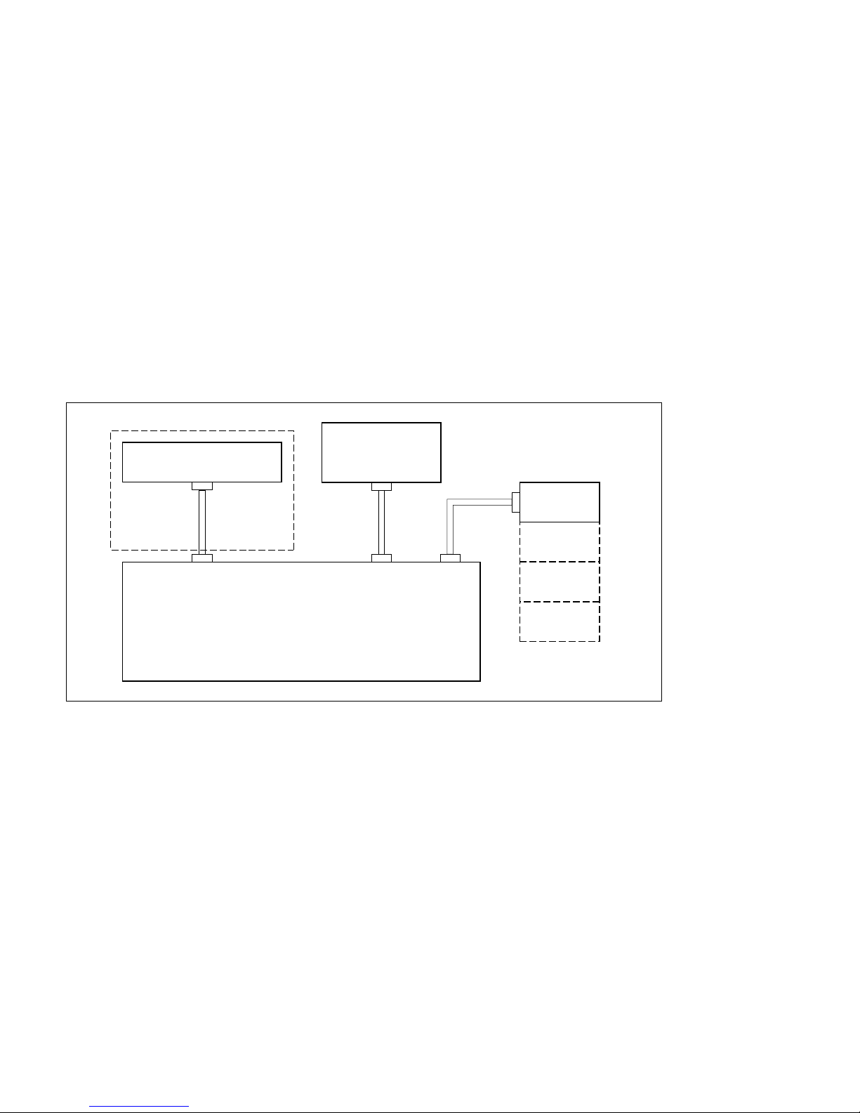
AUX BUS PANEL
DISPLAY
PANEL
ADAPTOR
BOX
(
BKDS-7075
)
AUX PANEL DISPLAY
PANEL
OPTION
PANEL
(*1) (*1) (*1)
(*2)
MAIN PANEL
(*3)
3-5. Installation of AUX BUS PANEL (Only BKDS-702x, 702xR and 702xLR)
3-6. Installation of Ten Key Unit (Only BKDS-70xxR/70xxLR)
3-7. Connection of Control Panel
3-5. Installation of AUX BUS PANEL (Only BKDS-702x, 702xR and 702xLR)
Secure to the console by the four screws (M4).
3-6. Installation of Ten Key Unit (Only BKDS-70xxR/70xxLR)
Secure to the console by the four screws (M4).
3-7. Connection of Control Panel
Use the BVS cables packed with the control panel.
Connection Main panel to the AUX BUS panel, display panel and adaptor box (only BKDS-70xxR/
70xxLR).
(*1) : Use the BVS cables packed with the control panel.
(*2) : Only BKDS-70xxR/70xxLR
(*3) : Only BKDS-702x/702xR/702xLR
Page 43
DVS-7000AE IM
3-15
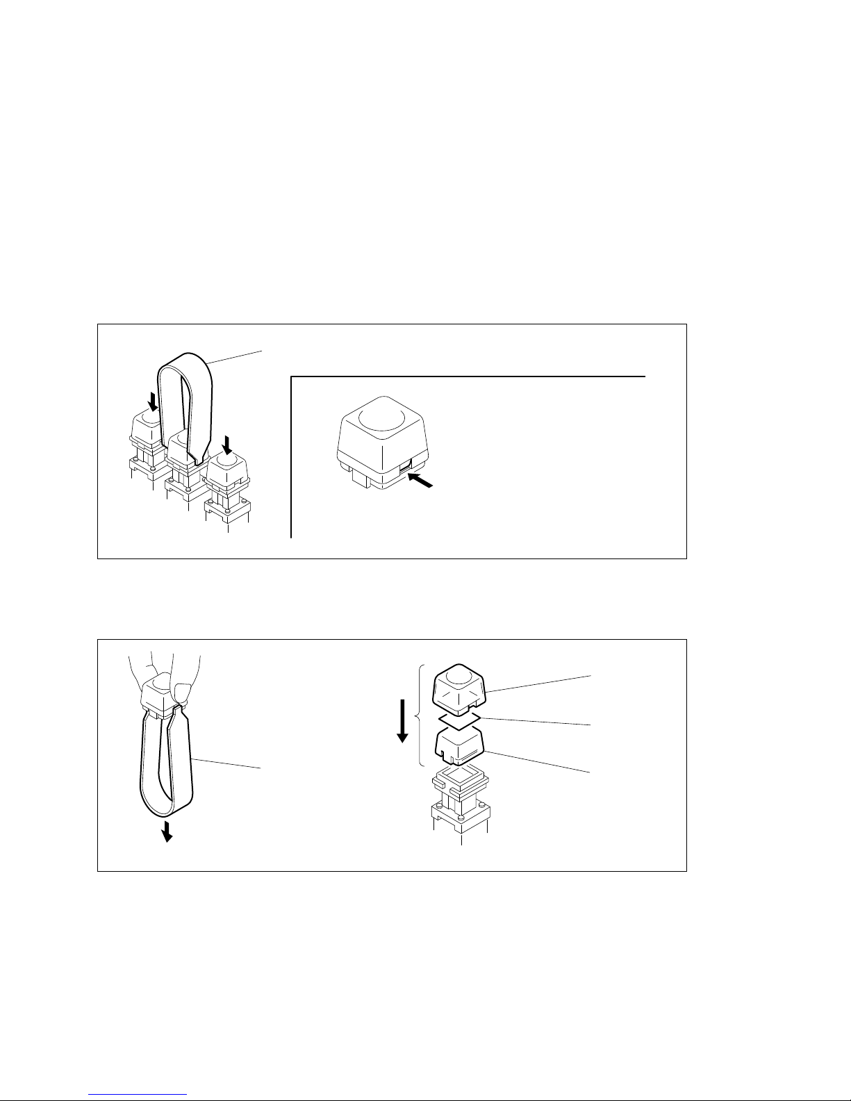
Key top
Switch tip
Diffusion plate
(Fig. 4)
Cap pull tool
(Fig. 3)
Cap pull tool
Hook the tool here and pull out thekey top.
(Fig. 2)(Fig. 1)
3-8. Replacement of Key Tops
3-8. Replacement of Key Tops
The control panels are supplied with a cap pull tool.
Remove or install the key top in the following procedures.
For removing the key tops, use the cap pull tool.
Part number: 3-179-054-01
(1) Push down the key top on both sides and insert the cap pull tool in the gap between key and sides.
(Fig. 1)
(2) Hold the key top to remove it. (Fig. 2)
(3) Remove the diffusion plate (milky white color) by the cap pull tool from the removed key top.
(4) Insert the switch tip between diffusion plate (milky white color) and key top (clear), and assemble
them by pushing in the key.
Page 44

Page 45

DVS-7000AE IM
4-1
Optional Equipments for DVS-7000A
Option Function name
BKDS-7103 (DI-36 board) 12Input Serial Digital Board
BKDS-7110 (ADC-21 board) Blank Input Adaptor Board
BKDS-7111 (ADI-3 board) Analog Composite Input Board
BKDS-7113 (DI-34 board) Serial Digital Input Board
BKDS-7133 (ADC-22 and ENC-34 boards) CRK Analog Component Input Board
BKDS-7161 (DA-94 board) Analog Composite Output Board
BKDS-7163 (SD-48 board) Serial Digital Output Board
BKDS-7270 (BD-26 board) Key Border Board
BKDS-7271 (BD-35 board) Fine Key/Key Border Board
BKDS-7280 (UP-10 board) ME PVW Board
BKDS-7420 (CC-81 board) Color Correction Board
BKDS-7445 (YC-59 board) Frame Memory Adaptor Board
BKDS-7690 (LE-55, RE-109 and RE-110 boards) Redundant Power Supply Unit
BKDS-2031 (CRK-10 board) Chromakey Board
BKDS-2032 (CRK-11 board) Chromakey Upgrade Board
BKDS-2041 (MY-66 board) Frame Memory Board
BKDS-2070 (WKG-12 board) Enhanced Wipe Generator Board
BZS-7020A
(*1)
Operation Software with Manual (E)
Optional Equipments for the control panels
Option Function name
BKDS-7001 (IF-523 board) Control Port Expansion Board
BKDS-7030 (KY-328 and LE-144 boards) Key Frame Control Panel Unit
BKDS-7031 (KY-329 board) DME Control Panel Unit
BKDS-7032 (KY-325 board) DSK Control Panel Unit (BKDS-701x/701xR/701xLR only)
BKDS-7033 (KY-395C board) Memory Recall Control Panel Unit
BKDS-7075 (IF-629 board) Control Panel Remote Adaptor
BKDS-7090 (RE-112 board) Redundant Power Supply Unit
(*1) : For installation of BZS-7020A, refer to the section 6 and BZS-7020A User’s Guide.
Section 4
Installation of Options
Page 46
4-2
DVS-7000AE IM
4-1. Installation of Plug-in Boards
4-1. Installation of Plug-in Boards
DVS-7000A can be used for various systems, and its functions can be extended by selecting the optional
boards. Each plug-in board must be installed in the corresponding slot of DVS-7000A. Confirm that all
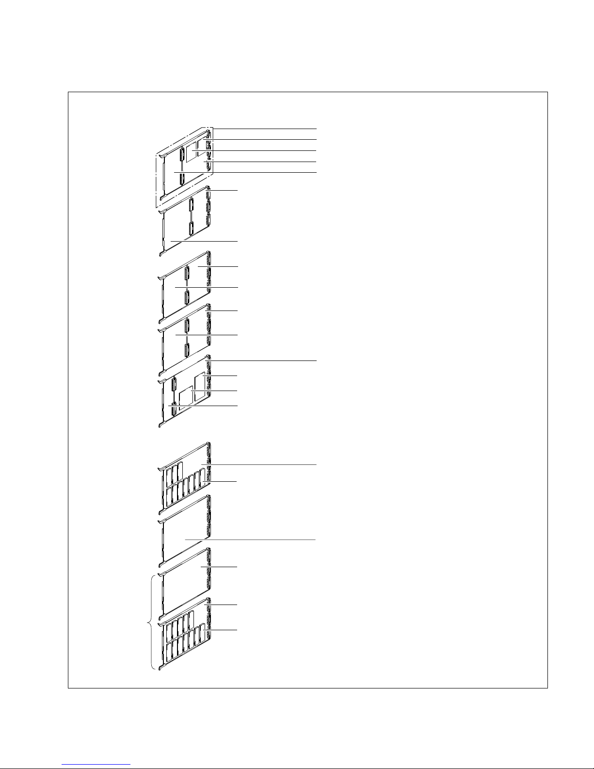
the boards are in the specified slots by referring to the following table.
For the details of how to install the plug-in board, refer to “4-3-2. Inserting/Pulling Out of Plug-in
Boards”.
The board name are displayed near the eject lever at the left side on the A side of each plug-in board. The
slot numbers that can be installed the board are displayed on the inside of the front panel of DVS-7000A.
Like the standard board, each optional boards should also be installed in the specified slot according to
the slot number display.
n
(1) Confirm that the connectors on each board are securely connected to the MB-618 board of the main
unit.
(2) If the board is installed in an incorrect slot, a system error occurs. Then the system is not properly
activated.
(3) Be sure to confirm the power supply voltage when an optional board is added or a board is replaced.
(Refer to “5-2. Adjustment of Secondary Power Supply Voltage”.)
1
CPU-2642YC-59
MY-66
CC-81
3 4
ENC-34
ADC-22
5
ENC-34
ADC-22
6
CRK-10
CRK-11
7
MIX-35
BD-26
BD-35
8
CRK-10
CRK-11
9
MIX-35
BD-26
BD-35
10
CRK-10
CRK-11
11
MIX-35
BD-26
BD-35
12
OUT-913OUT-914XPT-1615XPT-1616ADC-21
DI-36
17
ADC-21
DI-36
18
ADC-21
DI-36
Eject lever
Board name
(A side)
CPU-264
Page 47
DVS-7000AE IM
4-3
4-1. Installation of Plug-in Boards
Plug-in Boards
8 BKDS-2041
Frame memory board
9 BKDS-7133
Encoder board
0 BKDS-7133
CRK analog component input board
!- BKDS-2031
Chromakey board
!= BKDS-2032
Chromakey upgrade board
!. BKDS-7161
Analog composite output board
or
@/ BKDS-7163
Serial digital output board
!, Output processor board
@- Cross point board
@= BKDS-7103
12 input serial digital board
@] BKDS-7111
Analog composite input board
or
@\ BKDS-7113
Serial digital input board
@[ BKDS-7110
Blank input adaptor board
1
2
3 (Spare)
4 and 5
6, 8 and 10
7, 9 and 11
12 and 13
14 and 15
16, 17 and 18
2 IF-758 board
3 MEM-94 board
4 CA-35A board
5 CPU-264 board
2 Interface board
3 Memory board
1 CPU-264A board 1 System control board
4 Application board
5 System control board
6 BKDS-7420
Color correction board
or
7 BKDS-7445
Frame memory adaptor board
6 CC-81 board
or
7 YC-59 board
8 MY-66 board
9 ENC-34 board
0 ADC-22 board
!- CRK-10 board
!= CRK-11 board
![ Video mixer board
!] BKDS-7280
ME PVW board
!\ BKDS-2070
Enhanced wipe generator board
!; BKDS-7270
Key border board
or
!' BKDS-7271
Fine key/key border board
![ MIX-35 board
!] UP-10 board
!; BD-26 board
or
!' BD-35 board
!, OUT-9 board
!. DA-94 board
or
@/ SD-48 board
@- XPT-16 board
@= DI-36 board
@[ ADC-21 board
@] ADI-3 board
or
@\ DI-34 board
!\ WKG-12 board
Slot No. Option Board Standard Board Function Name
Page 48
4-4
DVS-7000AE IM
4-2. Combination of Optional boards
4-2. Combination of Optional boards
4-2-1. Function of Optional Boards
1. Input
. The primary inputs, 1 through 12, on the rear panel can be used if installing DI-36 board (BKDS-7103)
into Slot 16. Similarly, inputs 13-24 with DI-36 board installed in Slot 17, and inputs 25-36 with DI-36
board installed in Slot 18.
. The analog composite (NTSC) input can be used if installing ADI-3 board (BKDS-7111) onto ADC-21
board (BKDS-7110).
. The serial digital input can be used if installing DI-34 board (BKDS-7113) onto ADC-21 board
(BKDS-7110).
. The names for the ADI-3 and DI-34 boards printed on the ADC-21 board mean the name of the input
connector for DVS-7000A.
2. Output
. The analog composite output can be used if installing DA-94 board (BKDS-7161) onto the OUT-9
board.
. The serial digital input can be used if installing SD-48 board (BKDS-7163) onto OUT-9 board.
. The names for the DA-94 and SD-48 boards printed on the OUT-9 board mean the name of the output
connector for DVS-7000A.
4-2-2. Relation between Optional Boards and Rear Panel Connectors
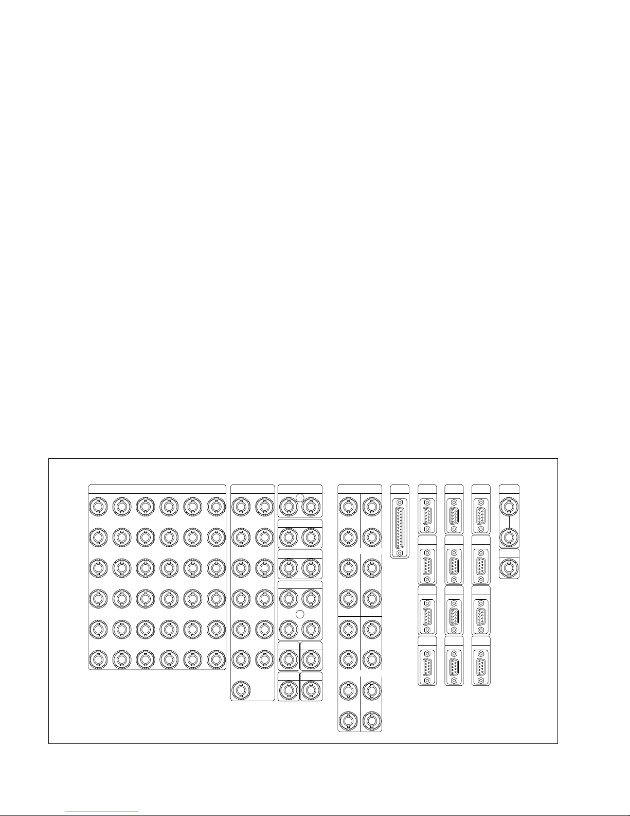
Install the applicable optional boards to the specified slots according to the signal to be input and output.
The following table shows the relations between rear panel connectors, signals to be input and output,
boards and slot numbers.
<DVS-7000A Rear Panel>
PRIMARY INPUTS GPI
TERMINAL
DSK
MATRIX
SERIAL
TALLY
DME 2
DME 4
PANEL 1
REF
INPUTS
REF
OUTPUT
DME 1
DME 3
AUX BUS
OUTPUTS
ME-1
OUTPUTS
ORK INPUT/
D1 PRIMALY INPUTS
ME-3
OUTPUTS
PGM
OUTPUTS
CLEAN
OUTPUT
PST
OUTPUT
EDIT PVW
OUTPUT
DIRECT
INPUT
ME-2
OUTPUTS
1
2
3
4
5
6
Y/G
B-Y/B
R-Y/R
SYNC
Y/G
B-Y/B
R-Y/R
SYNC
Y/G
B-Y/B
R-Y/R
SYNC
Y/G
B-Y/B
R-Y/R
SYNC
1
2
1
2
3
4
3
4
5
6
7
8
9
10
11
12
13
7
8
9
10
11
12
19
20
21
22
23
24
25
26
27
28
29
30
31
32
33
34
35
36
13
14
15
16
17
18
CH 3 CH 1
CH 4 CH 2
PANEL 2
/REMOTE 3
EDITOR B
/REMOTE 2
EDITOR A
/REMOTE 1
Page 49

DVS-7000AE IM
4-5
4-2. Combination of Optional boards
Input : When using BKDS-7110 (ADC-21 board)
Slot Optional Parent Board Rear Panel Connector
No. Input Board ADC-21
16 ADI-3
(*3)
CN101, 102 PRIMARY INPUT 1
(BKDS-7111) CN201, 202 PRIMARY INPUT 2
or CN301, 302 PRIMARY INPUT 3
DI-34
(*4)
CN401, 402 PRIMARY INPUT 4
(BKDS-7113) CN501, 502 PRIMARY INPUT 5
CN601, 602 PRIMARY INPUT 6
CN701, 702 PRIMARY INPUT 7
CN801, 802 PRIMARY INPUT 8
CN901, 902 PRIMARY INPUT 9
CN1001, 1002 PRIMARY INPUT 10
CN1101, 1102 PRIMARY INPUT 11
CN1201, 1202 PRIMARY INPUT 12
17 ADI-3
(*3)
CN101, 102 PRIMARY INPUT 13
(BKDS-7111) CN201, 202 PRIMARY INPUT 14
or CN301, 302 PRIMARY INPUT 15
DI-34
(*4)
CN401, 402 PRIMARY INPUT 16
(BKDS-7113) CN501, 502 PRIMARY INPUT 17
CN601, 602 PRIMARY INPUT 18
CN701, 702 PRIMARY INPUT 19
CN801, 802 PRIMARY INPUT 20
CN901, 902 PRIMARY INPUT 21
CN1001, 1002 PRIMARY INPUT 22
CN1101, 1102 PRIMARY INPUT 23
CN1201, 1202 PRIMARY INPUT 24
18 ADI-3
(*3)
CN101, 102 PRIMARY INPUT 25
(BKDS-7111) CN201, 202 PRIMARY INPUT 25
or CN301, 302 PRIMARY INPUT 27
DI-34
(*4)
CN401, 402 PRIMARY INPUT 28
(BKDS-7113) CN501, 502 PRIMARY INPUT 29
CN601, 602 PRIMARY INPUT 30
CN701, 702 PRIMARY INPUT 31
CN801, 802 PRIMARY INPUT 32
CN901, 902 PRIMARY INPUT 33
CN1001, 1002 PRIMARY INPUT 34
CN1101, 1102 PRIMARY INPUT 35
CN1201, 1202 PRIMARY INPUT 36
(*3) : For analog composite input signal
(*4) : For serial digital input signal
Output
Slot Optional Parent Board Rear Panel Connector
No. Output Board OUT-9
12 DA-94
(*1)
CN1, 2 AUX BUS OUTPUT 1
(BKDS-7161) CN3, 4 AUX BUS OUTPUT 2
or CN5, 6 AUX BUS OUTPUT 3
SD-48
(*2)
CN7, 8 AUX BUS OUTPUT 4
(BKDS-7163) CN9, 10 AUX BUS OUTPUT 5
CN11, 12 AUX BUS OUTPUT 6
CN13, 14 EDIT PVW OUTPUT
CN15, 16 PGM OUTPUT
CN17, 18 PST OUTPUT
CN19, 20 CLEAN OUPUT
13 DA-94
(*1)
CN1, 2 AUX BUS OUTPUT 7
(BKDS-7161) CN3, 4 AUX BUS OUTPUT 8
or CN5, 6 AUX BUS OUTPUT 9
SD-48
(*2)
CN7, 8 AUX BUS OUTPUT 10
(BKDS-7163) CN9, 10 AUX BUS OUTPUT 11
CN11, 12 AUX BUS OUTPUT 12
CN13, 14 AUX BUS OUTPUT 13
CN15, 16 ME-3 OUTPUT
CN17, 18 ME-2 OUTPUT
CN19, 20 ME-1 OUPUT
(*1) : For analog composite output signal
(*2) : For serial digital output signal
Page 50
4-6
DVS-7000AE IM
4-3. Installation of Options for DVS-7000A
4-3. Installation of Options for DVS-7000A
This section is described the installation procedures of the optional equipments that are installed to DVS7000A.
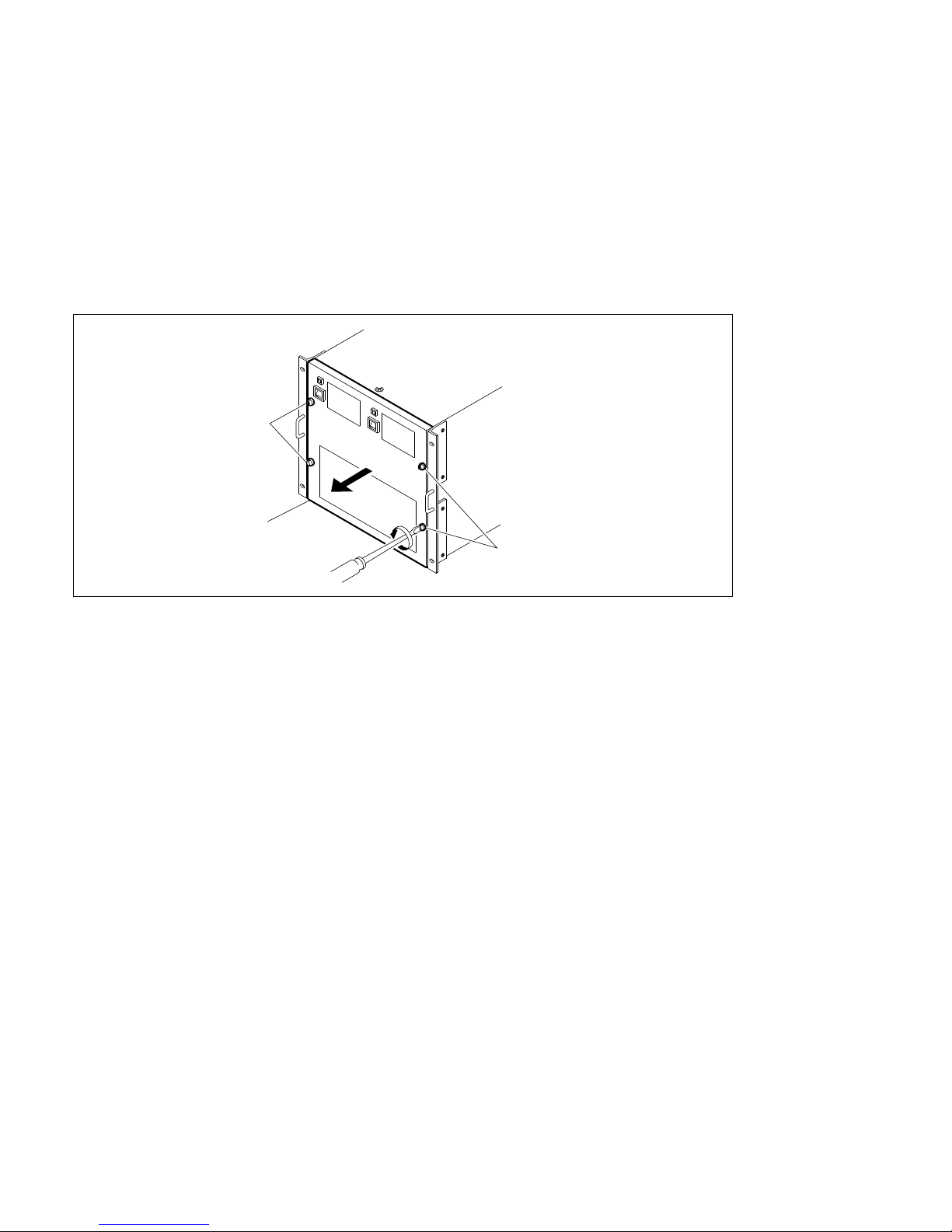
4-3-1. Detaching and Attaching of Front Panel
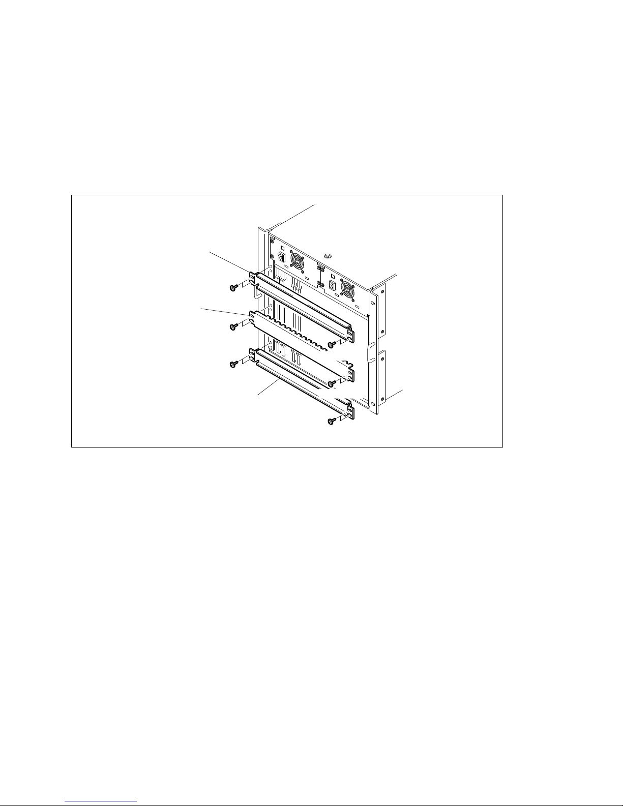
(1) Loosen the four locking screws on the front panel using a flatblade screwdriver.
(2) Detach the front panel in the direction of the arrow.
(3) Attach the front panel in the reverse order of the steps (1) and (2).
Front panel
Locking screws
Locking screws
Page 51
DVS-7000AE IM
4-7
4-3. Installation of Options for DVS-7000A
4-3-2. Inserting/Pulling Out of Plug-in Boards
c
To avoid shock hazards and/or damage to the boards, be sure to turn off the power switch before inserting
or pulling out the plug-in boards.
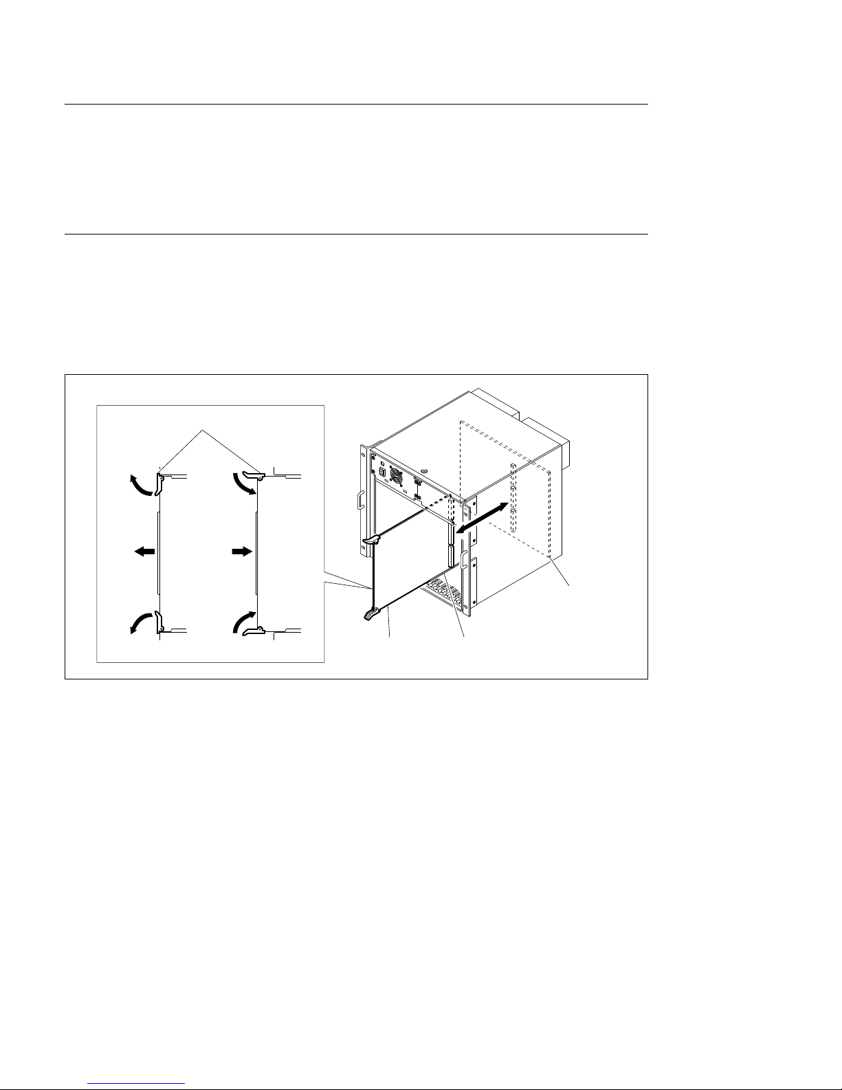
(1) Detach the front panel. (Refer to “4-3-1. Detaching and Attaching of Front Panel”.)
(2) Remove the twelve screws, the two board retainer and the one board holder.
PWH4 x 6
PWH4 x 6
PWH4 x 6
Board holder
Board retainer
Board retainer
PWH4 x 6
PWH4 x 6
PWH4 x 6
Page 52
4-8
DVS-7000AE IM
4-3. Installation of Options for DVS-7000A
Removal
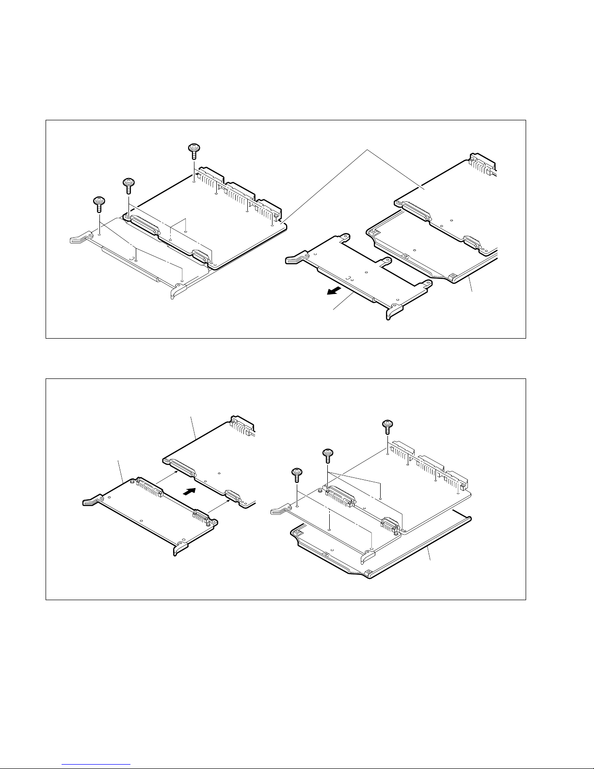
(3) Open the eject levers of the plug-in board in the direction of the arrows 1.
(4) Pull out the plug-in board from the unit.
n
Pull out the plug-in board with a equal force for both eject levers.
Installation
(5) Insert the plug-in board along the board guide rails while putting the eject levers to the direction of
the arrows 1 as shown in the figure.
(6) Connect the plug-in board to the connector on the mother board by putting the eject levers in the
direction of the arrows 2.
(7) Install the two board retainer and the one board holder in the reverse order of the steps (1) and (2).
1
1
2
2
Eject lever
Board
MB-618 board
Board guide rail
Page 53

DVS-7000AE IM
4-9
4-3. Installation of Options for DVS-7000A
4-3-3. Installation of Optional Boards
There are the three installation types of the optional boards in DVS-7000A.
<Type 1> The type that the optional board is inserted in the slot.
<Type 2> The type that the optional board is connected onto the connector of the pre-installed board and
is secured by the screws.
<Type 3> The type that the optional board is connected onto the connector of the pre-installed board.
The installation procedures are described below.
<Type 1>
This Type’s Optional Boards
Slot No. Optional board
2 CC-81 board (BKDS-7420)
or
YC-59 board (BKDS-7445)
4, 5 ADC-22 and ENC-34 boards (BKDS-7133)
6, 8, 10 CRK-10 board (BKDS-2031)
16 to 18 DI-36 board (BKDS-7103)
ADC-21 board (BKDS-7110)
(1) Install the optional board. (Refer to “4-3-2. Inserting/Pulling Out of Plug-in Boards”.)
<Type 2>
This Type’s Optional Boards
Slot No. Optional board Pre-installed board
2 MY-66 board (BKDS-2041) CC-81 board (BKDS-7420)
or
YC-59 board (BKDS-7445)
6, 8, 10 CRK-11 board (BKDS-2032) CRK-10 board (BKDS-2031)
7, 9, 11 BD-26 board (BKDS-7270) MIX-35 board
or
BD-35 board (BKDS-7271)
Page 54
4-10
DVS-7000AE IM
4-3. Installation of Options for DVS-7000A
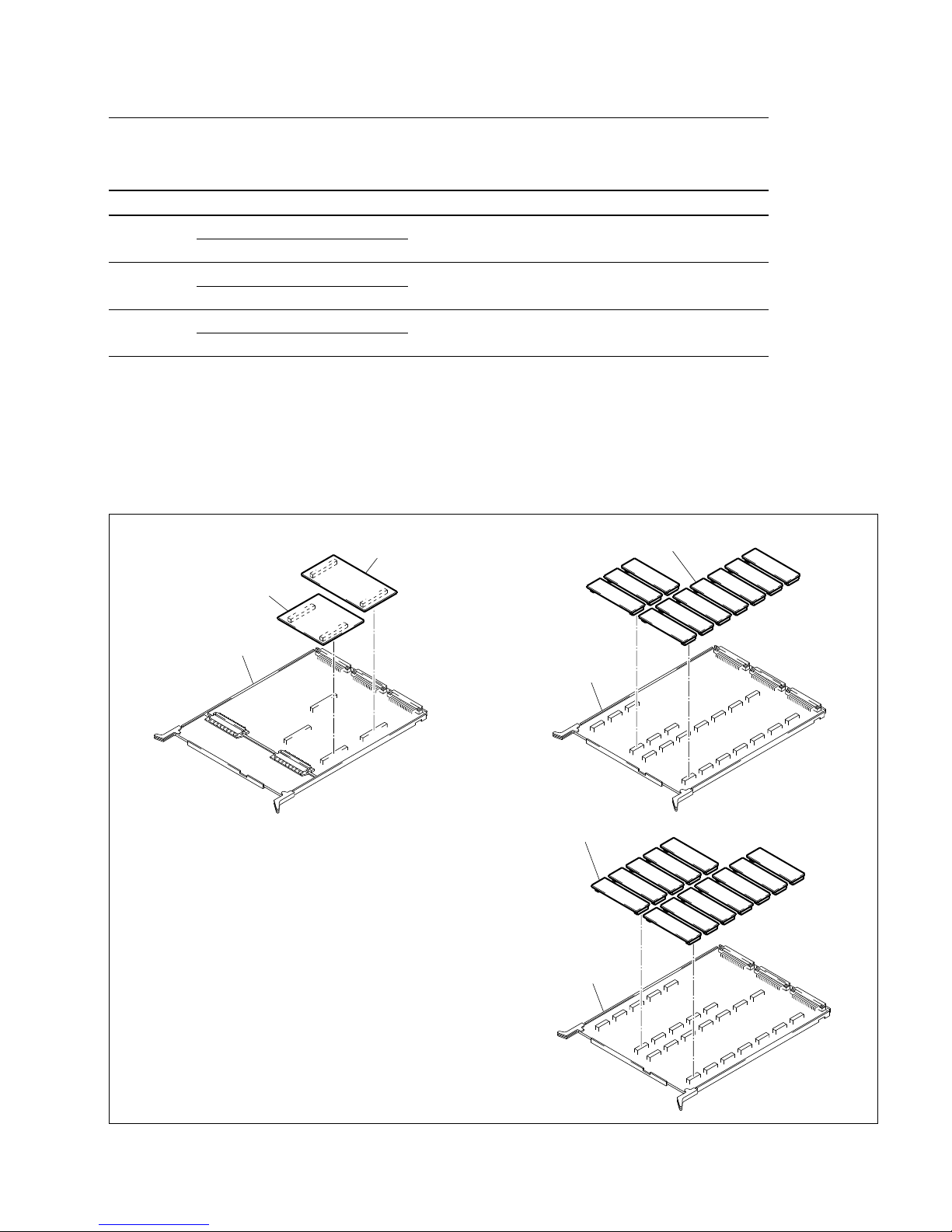
Install the optional board to the pre-installed board or the optional board in the following procedures.
(1) Remove the eleven screws secured to the pre-installed board, shield plate and dummy plate.
(2) Connect the optional board to the connectors on the pre-installed board.
(3) Secure the optional board and shield plate by ten screws.
PTTWH3 x 6
PTTWH3 x 6
PTTWH3 x 6
Shield plate
Optinal board
Pre-installed board
PTTWH3 x 6
PTTWH3 x 6
PTTWH3 x 6
Pre-installed boards
Dummy plate
Shield plate
Page 55
DVS-7000AE IM
4-11
MIX-35 board
WKG-12 board
UP-10 board
<Type 3>
This Type’s Optional Boards
Slot No. Optional board Pre-installed board
7, 9, 11 UP-10 board( BKDS-7280)
MIX-35 board
WKG-12 board (BKDS-2070)
12, 13 DA-94 board (BKDS-7161)
OUT-9 board
SD-48 board (BKDS-7163)
16 to 18 ADI-3 board (BKDS-7111)
ADC-21 board (BKDS-7110)
DI-34 board (BKDS-7113)
After checking the installation direction of the optional board by its connector number, connect the
optional board to the connectors on the pre-installed board.
n
When installing the optional boards, confirm that the connectors are tightly connected. If the connectors
cannot be completely connected, the optional board may be placed in the other way.
4-3. Installation of Options for DVS-7000A
OUT-9 board
DA-94 board or SD-48 board
ADC-21 Board
ADI-3 Board or DI-34 Board
Page 56
4-12
DVS-7000AE IM
4-3. Installation of Options for DVS-7000A
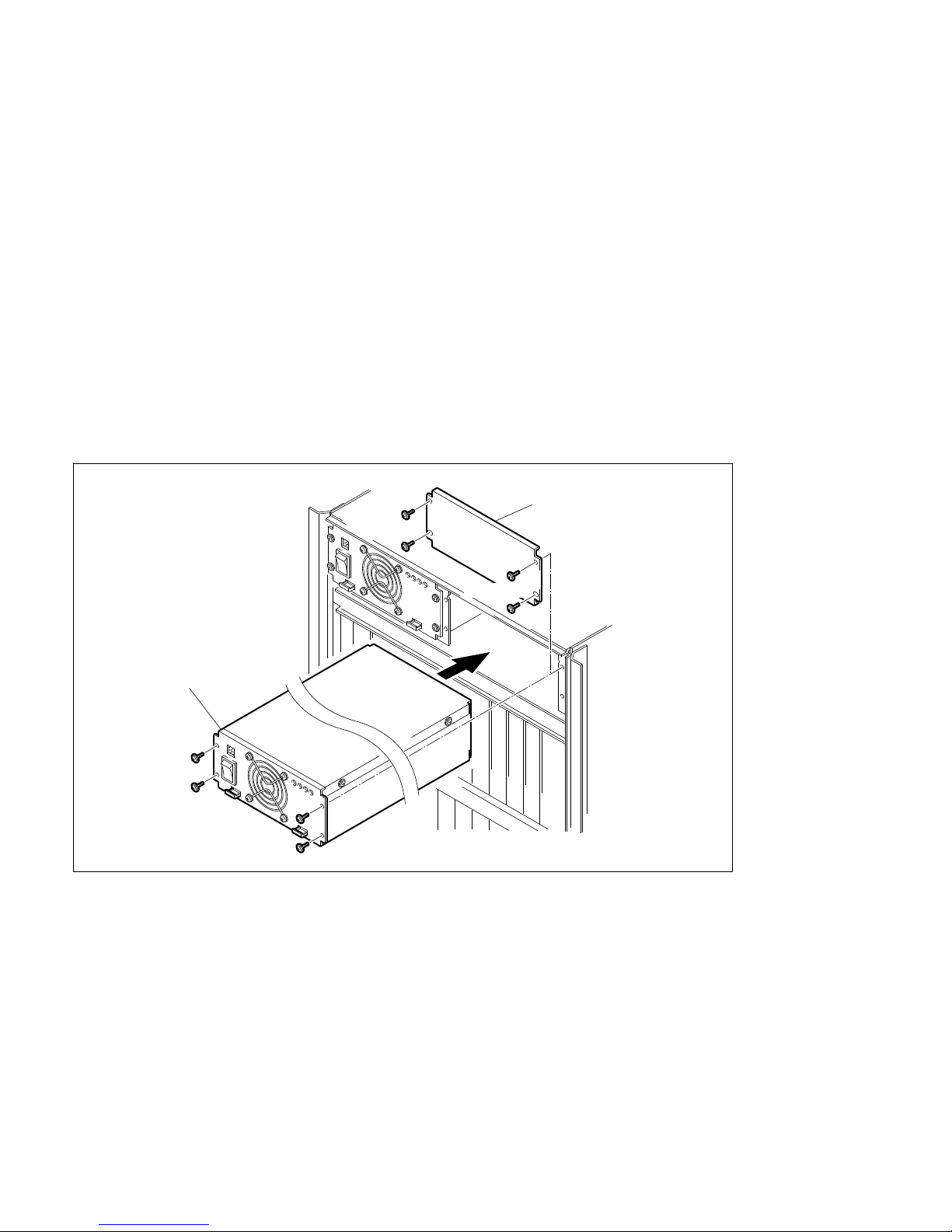
4-3-4. Installation of BKDS-7690 (Redundant Power Supply Unit)
w
To avoid shock hazards, be sure to turn off the breaker at the outside of DVS-7000A or unplug the power
cord when installing BKDS-7690.
Contents
Power unit : 1pc
Screw (PWH4 x 6) : 4pcs
(1) Detach the front panel of DVS-7000A. (Refer to “4-3-1. Detaching and Attaching of Front Panel”.)
(2) Remove the pre-installed blank panel of BKDS-7690 as shown in the following figure.
(Four screws PWH4 x 6)
(3) Properly insert BKDS-7690 to the pre-install position.
(4) Secure BKDS-7690 to DVS-7000A by the four screws (PWH4 x 6) supplied with BKDS-7690.
(5) Turn on the power switch of BKDS-7690.
PWH4 x 6
PWH4 x 6
PWH4 x 6
BKDS-7690
Blank panel
PWH4 x 6
Page 57
DVS-7000AE IM
4-13
Display panel
4-4. Installation of Options for Control Panel
4-4. Installation of Options for Control Panel
This section is described the installation procedures of the optional equipments that are installed to the
control panel.
c
To avoid shock hazards and/or damage to the boards, be sure to turn off the breaker at the outside of the
unit or unplug the power cord when installing the optional equipments.
4-4-1. Opening and Closing of Panel
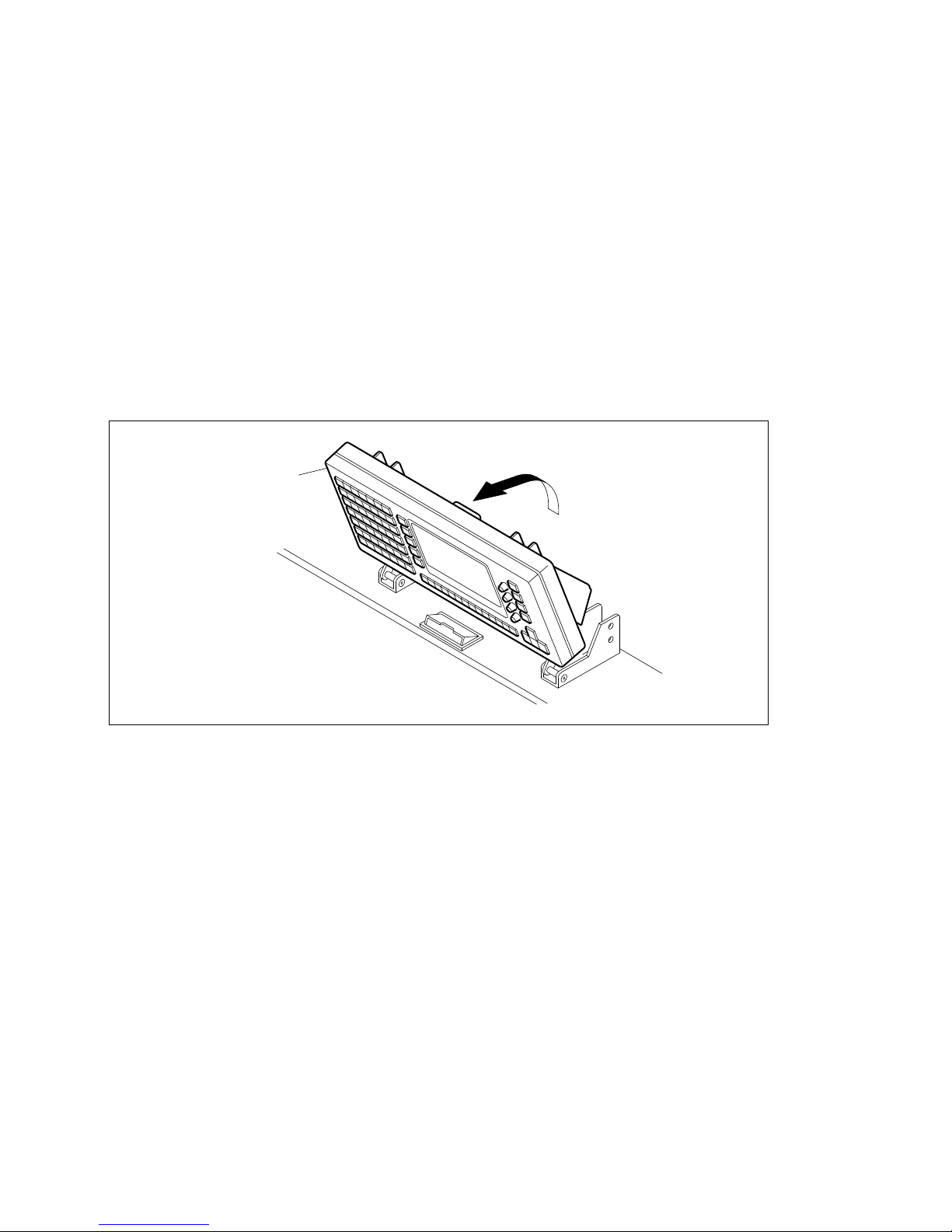
n
When opening and closing the panel of BKDS-701x, 701xR or 701xLR, tilt the display panel forward.
If not, the display panel is touched against the unit with placed at the back.
Page 58
4-14
DVS-7000AE IM
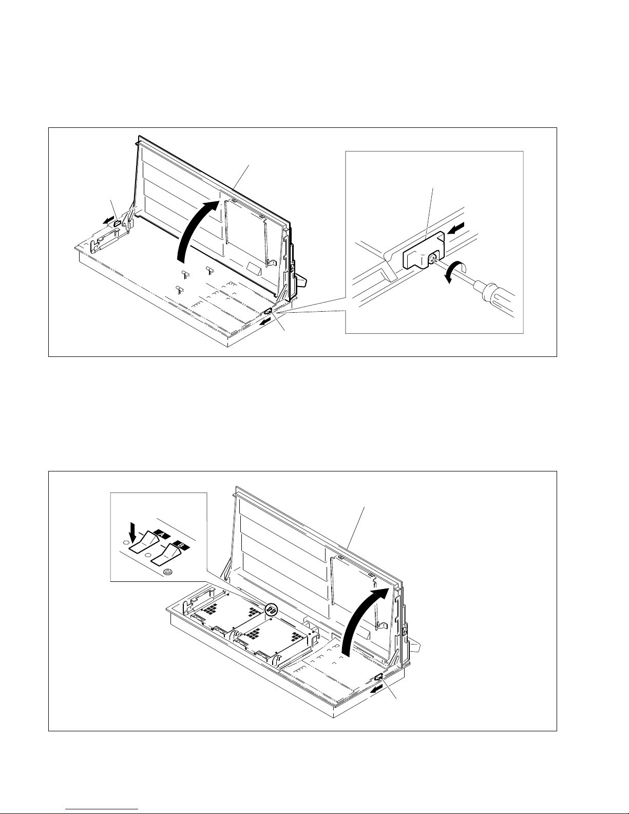
Slide knob
Slide knob
Control panel
Slide knob
4-4. Installation of Options for Control Panel
(1) Loosen the screws of the slide knobs at both sides of the panel.
(2) Move the slide knobs forward and release the locks.
(3) Push up the panel and open it.
(4) Push down the panel until the slide knobs are locked, and close it.
(5) Tighten the screws of the slide knobs at both sides of the panel.
4-4-2. Turning On/Off the Power Switch
(1) Open the panel of control panel. (Refer to “4-4-1. Opening and Closing of Panel”.)
(2) Turn off the power switches A and B in the control panel.
Power switch
OFF
Control panel
Slide knobs (Right and Left)
A
Page 59
DVS-7000AE IM
4-15
4-4. Installation of Options for Control Panel
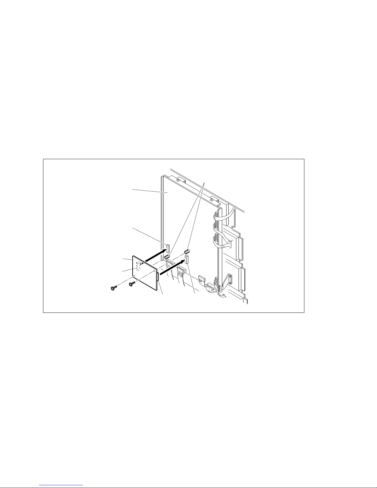
4-4-3. Installation of BKDS-7001 (Control Port Expansion Board)
Contents
IF-523 board : 1pc
Screw (PSW3 x 8) : 2pcs
(1) Open the panel. (Refer to “4-4-1. Opening and Closing of Panel”.)
(2) Turn off the power switches in the control panel.
(Refer to “4-4-2. Turning On/Off the Power Switch”.)
(3) Connect the CN1 on the IF-523 board to the CN12 on the CPU-263 board. Connect the CN2 on the
IF-523 board to the CN13 on the CPU-263 board.
(4) Secure the IF-523 board to the supports on the CPU-263 board by the two screws (PSW3 x 8)
supplied with BKDS-7001.
(5) Turn on the power switches in the control panel.
(If the one power unit is installed, turn on the power switch of the installed power unit.)
(Refer to “4-4-2. Turning On/Off the Power Switch”.)
(6) Close the panel. (Refer to “4-4-1. Opening and Closing of Panel”.)
CPU-263 board
CN12
CN13
CN2
CN1
BKDS-7001
(IF-523 board)
PSW3 x 8
Supports
Page 60
4-16
DVS-7000AE IM
4-4. Installation of Options for Control Panel
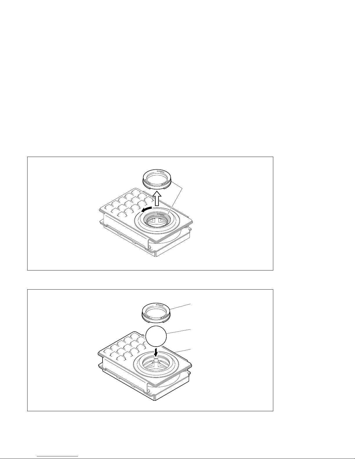
4-4-4. Installation of BKDS-7031 Track Ball
Contents
DME panel (KY-329 board) : 1 pc
Track ball : 1 pc
Harness (CTRL5) : 1 pc
Harness (DC9) : 1 pc
Screws (PSW3 x 8) : 4 pcs
n
For BKDS-7031 is installed to the control panel, refer to “4-4-5. Installation of Optional Panels (BKDS7030/7031/7032/7033)”.
(1) Turn the ball retainer counterclockwise to release a lock.
(2) Install the track ball and the ball retainer.
Ball retainer
Track ball
BKDS-7031
Ball retainer
Page 61
DVS-7000AE IM
4-17
4-4. Installation of Options for Control Panel
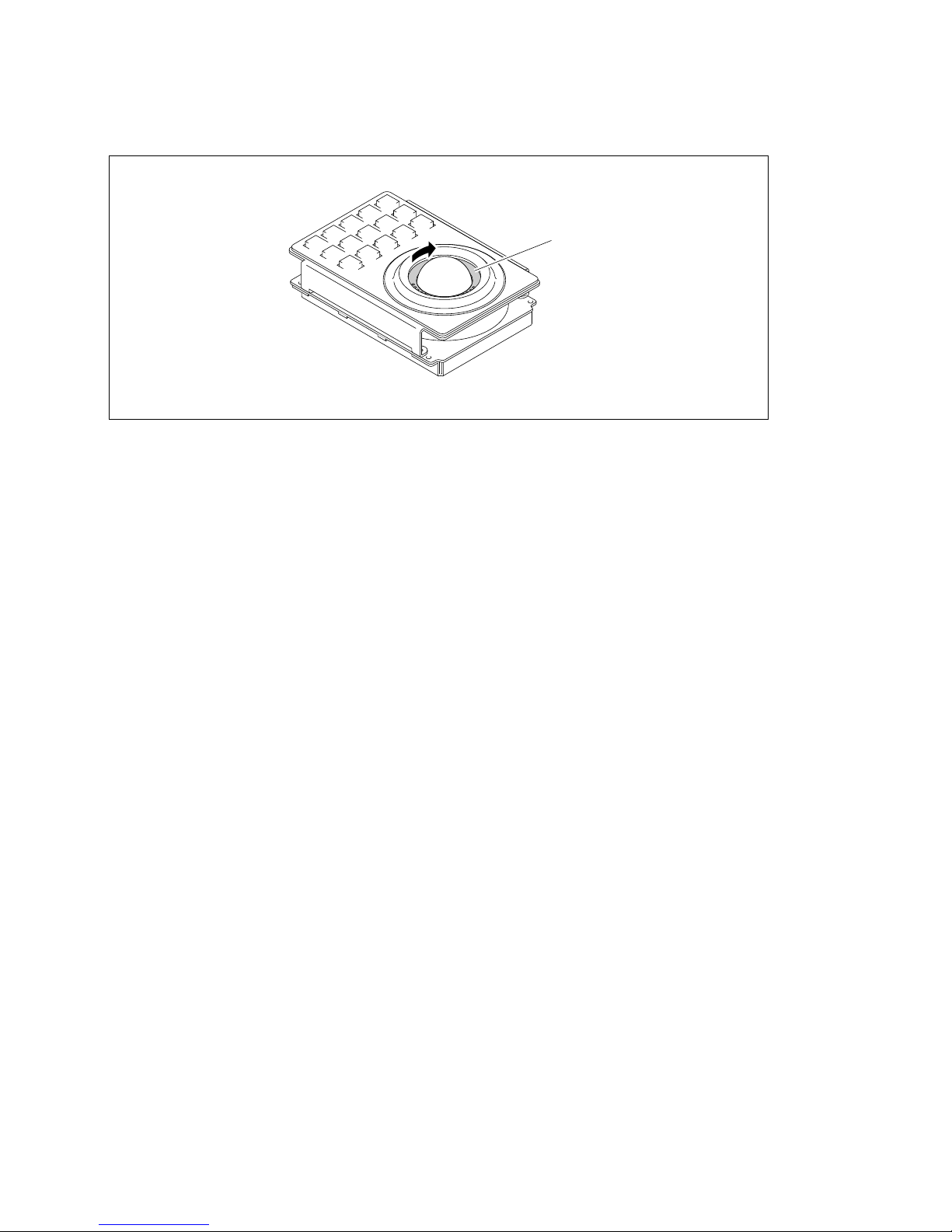
Ball retainer
(3) Turn the ball retainer clockwise to lock.
Page 62

4-18
DVS-7000AE IM
4-4. Installation of Options for Control Panel
4-4-5. Installation of Option Panels (BKDS-7030/7031/7032/7033)
Contents of BKDS-7030
Key Frame Control Panel Unit (KY-328 board) : 1 pc
Harness (CTRL5) : 1 pc
Harness (DC9) : 1 pc
Screws (PSW3 x 8) : 4 pcs
Contents of BKDS-7031
DME Control Panel Unit (KY-329 board) : 1 pc
Harness (CTRL5) : 1 pc
Harness (DC9) : 1 pc
Screw (PSW3 x 8) : 4 pcs
Contents of BKDS-7032
DSK Control Panel Unit (KY-325 board) : 1 pc
Harness (CTRL5) : 1 pc
Harness (DC9) : 1 pc
Screw (PSW3 x 8) : 4 pcs
Contents of BKDS-7033
Memory Recall Control Panel Unit (KY-395C board) : 1 pc
Harness (CTRL5) : 1 pc
Harness (DC9) : 1 pc
Screw (PSW3 x 8) : 4 pcs
n
. After installing a track ball to BKDS-7031, install BKDS-7031 to the control panel.
(Refer to “4-4-4. Installation of BKDS-7031 Track Ball”.)
. Be sure to use BKDS-7032 only for BKDS-701x/701xR/701xLR.
Page 63
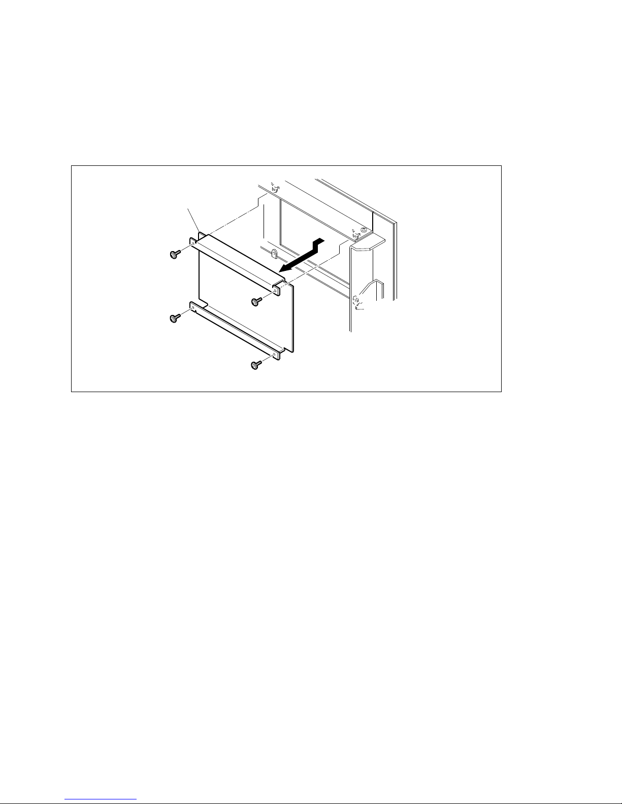
DVS-7000AE IM
4-19
4-4. Installation of Options for Control Panel
1. Installation to Main Panel (BKDS-701x)
(1) Open the panel. (Refer to “4-4-1. Opening and Closing of Panel”.)
(2) Turn off the power switch in the control panel. (Refer to “4-4-2. Turning On/Off the Power Switch”.)
(3) Remove the four screws (PWH3 x 8) securing to the blank panel and the blank panel in the direction
of the arrow.
Blank panel
PWH3 x 8
PWH3 x 8
PWH3 x 8
PWH3 x 8
Page 64
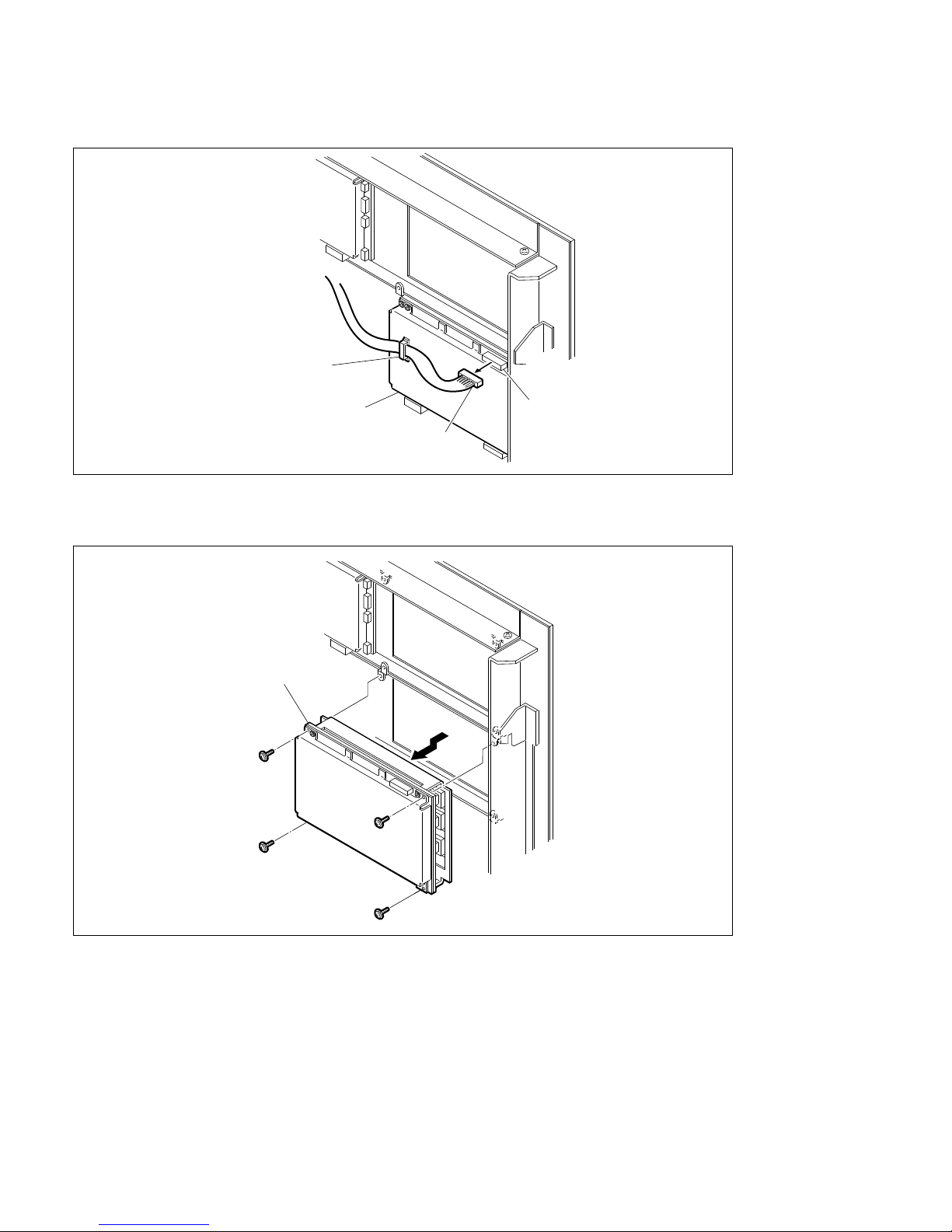
4-20
DVS-7000AE IM
4-4. Installation of Options for Control Panel
(4) Disconnect the harness from the CN1 on the KY-324 board.
(5) To change the position of the KY-324 board, remove the four fixing screws (PWH3 x 8) KY-324
board then remove the KY-324 board in the direction of arrow.
KY-324 board
CN1
Harness
Clamp
PWH3 x 8
PWH3 x 8
PWH3 x 8
KY-324 board
PWH3 x 8
Page 65
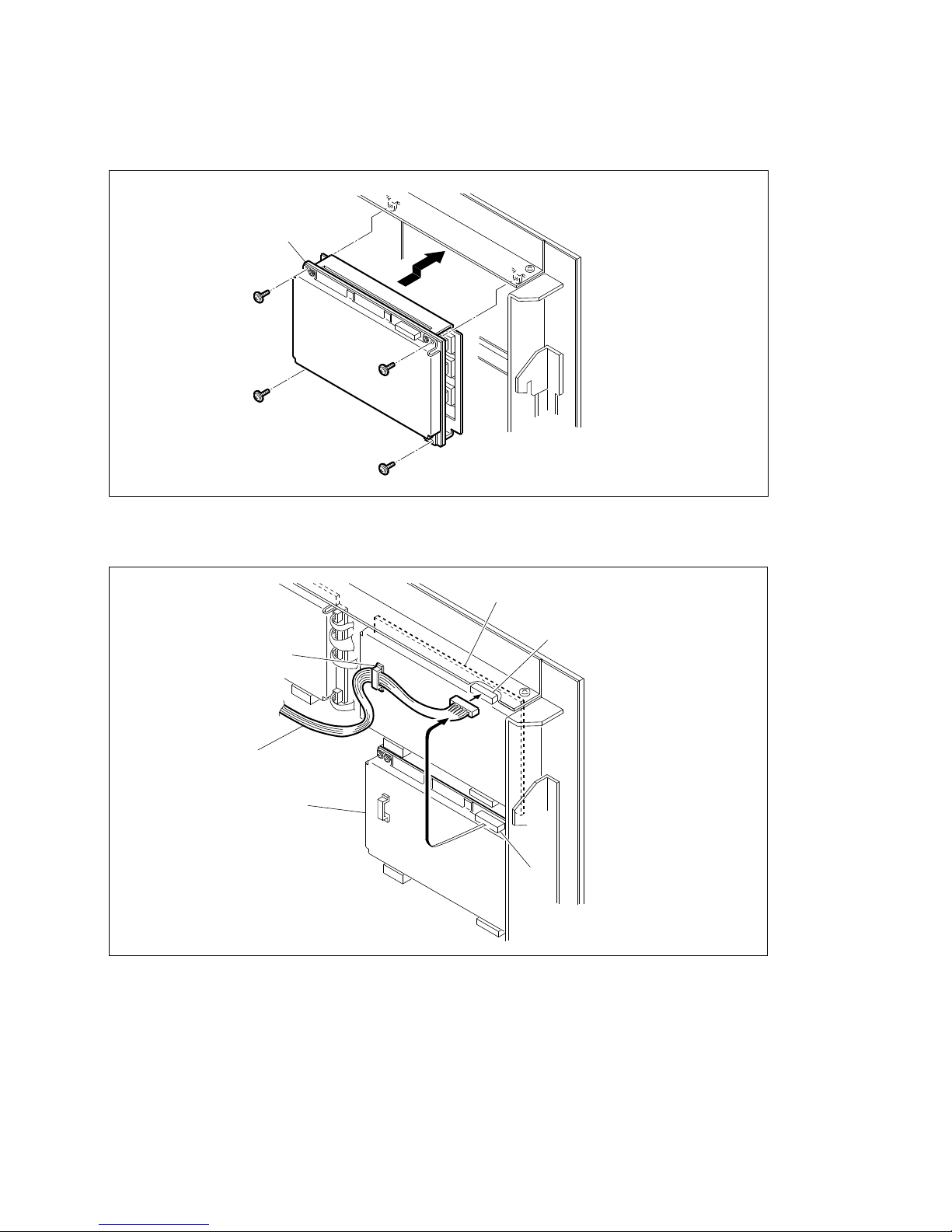
DVS-7000AE IM
4-21
4-4. Installation of Options for Control Panel
(6) Place the option panel and the KY-324 board to the desired position with the supplied screws or the
four screws (PSW3 x 8) removed from the KY-324 board.
(7) Connect the harness, which has been disconnected from the KY-324 board in the step (4), to CN1 on
the option panel located at the top of the frame.
PWH3 x 8
PWH3 x 8
PWH3 x 8
Option panel
(or KY-324 board)
PWH3 x 8
KY-324 board
CN1
CN1
Clamp
Harness
Option panel
Page 66
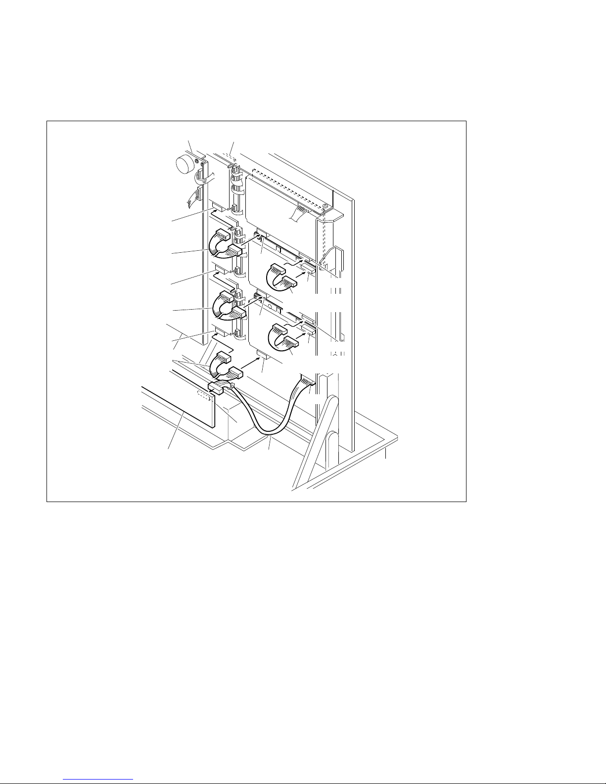
4-22
DVS-7000AE IM
4-4. Installation of Options for Control Panel
(8) Connect two harnesses (CTRL5 and DC9) as shown in the figure below. Also, when using the
adapter box (BKDS-7075), connect the harness (CTRL10) which is supplied with adapter box
(BKDS-7075) as shown in the figure below.
(9) Turn on the power switches in the control panel.
(Refer to “4-4-2. Turning On/Off the Power Switch”.)
(10) Close the panel. (Refer to “4-4-1. Opening and Closing of Panel”.)
CPU-263 board
KY-320 board
CN4
Harness (DC9)
Harness (CTRL5)
CN4
CN2
CN1
CN3
Harness (CTRL5)
CN2
CN1
CN3
CN3
CN2
Harness (CTRL10)
CN-1143 board
Harness (DC9)
CN4
Harness (DC9)
CN18
Page 67
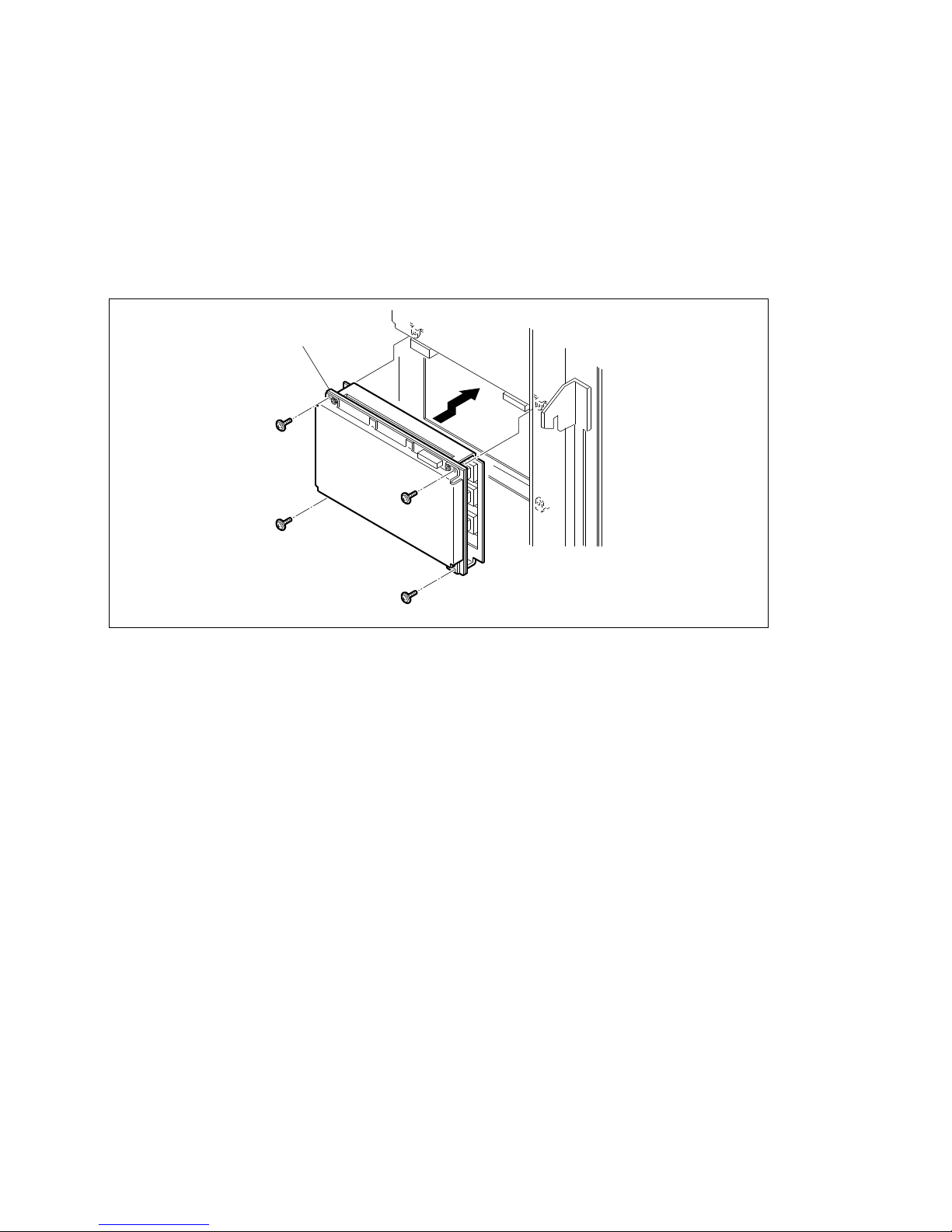
DVS-7000AE IM
4-23
4-4. Installation of Options for Control Panel
2. Installation to Main Panel (BKDS-702x)
(1) Open the panel. (Refer to “4-4-1. Opening and Closing of Panel”.)
(2) Turn off the power switch in the control panel. (Refer to “4-4-2. Turning On/Off the Power Switch”.)
(3) Remove the blank panel.
(Refer to the step (3) of “1. Installation to Main Panel (BKDS-701x)” in the section 4-4-5.)
(4) Put option panel to the position with removed the blank panel at the step (3) and secure it by the
supplied four screws (PSW3 x 8).
Option panel
PWH3 x 8
PWH3 x 8
PWH3 x 8
PWH3 x 8
Page 68
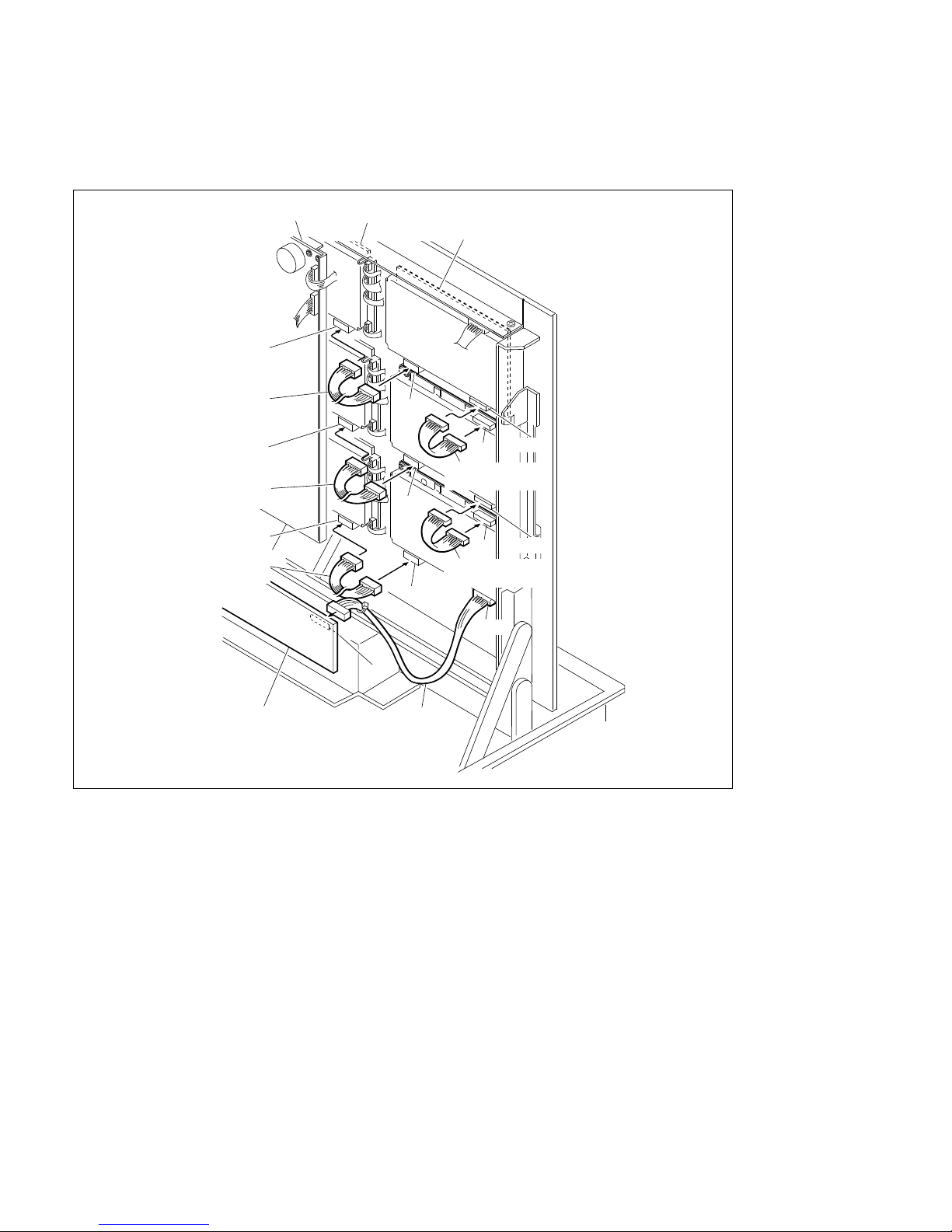
4-24
DVS-7000AE IM
4-4. Installation of Options for Control Panel
(5) Connect two harnesses (CTRL5 and DC9) as shown in the figure below. Also, when using the
adapter box (BKDS-7075), connect the harness (CTRL10) which is supplied with adapter box
(BKDS-7075) as shown in the figure below.
(6) Turn on the power switches in the control panel.
(Refer to “4-4-2. Turning On/Off the Power Switch”.)
(7) Close the panel. (Refer to “4-4-1. Opening and Closing of Panel”.)
CPU-263 board
KY-322 board
CN4
Harness (DC9)
Harness (CTRL5)
CN4
CN2
CN1
CN3
Harness (CTRL5)
CN2
CN1
CN3
CN3
CN2
Harness (CTRL10)
CN-1143 board
Harness (DC9)
CN4
Harness (DC9)
CN18
KY-324 board
Page 69
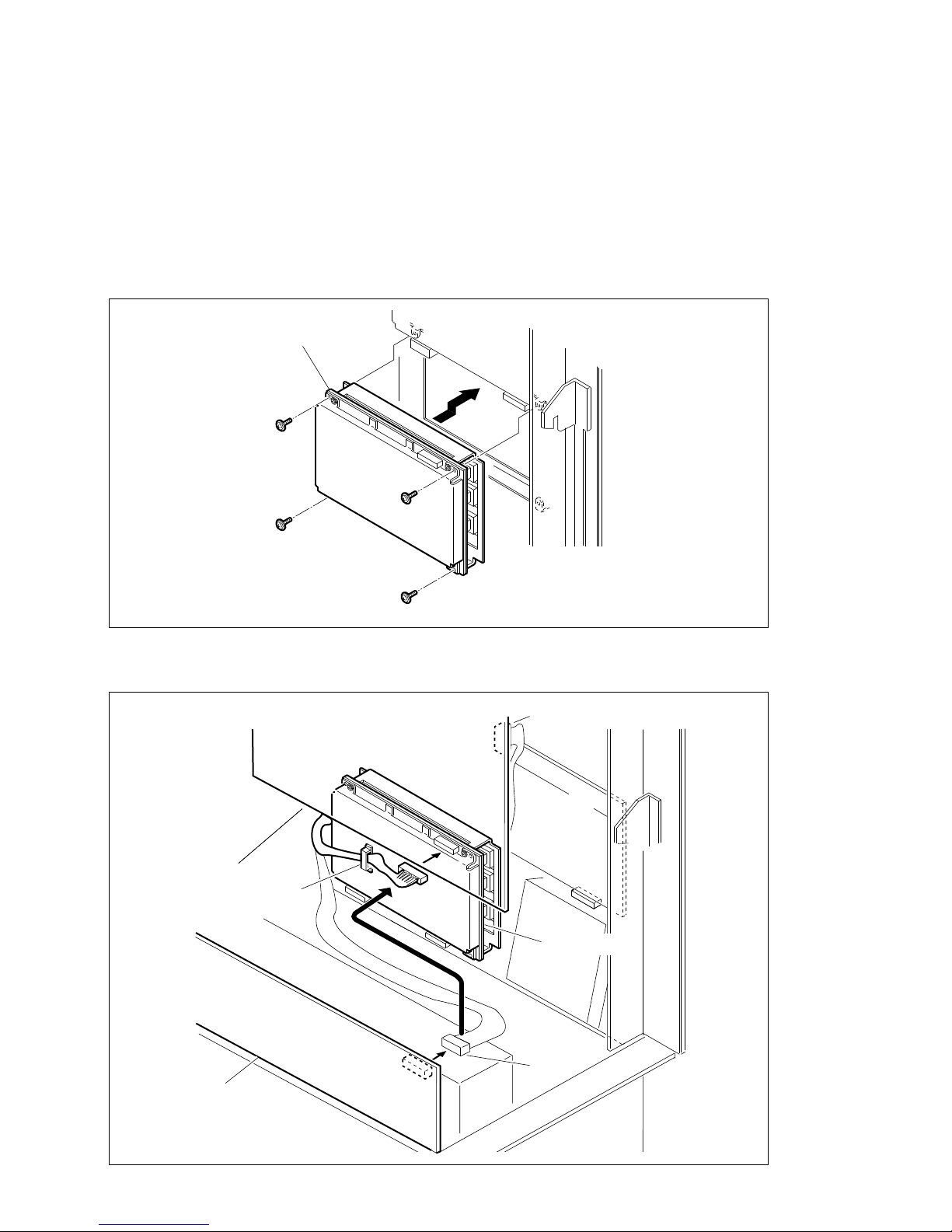
DVS-7000AE IM
4-25
4-4. Installation of Options for Control Panel
3. Installation to Main Panel (BKDS-7011R/7011LR)
(1) Open the panel. (Refer to “4-4-1. Opening and Closing of Panel”.)
(2) Turn off the power switch in the control panel. (Refer to “4-4-2. Turning On/Off the Power Switch”.)
(3) Remove the blank panel.
(Refer to the step (3) of “1. Installation to Main Panel (BKDS-701x)” in the section 4-4-5.)
(4) Put option panel to the position with removed the blank panel at the step (3) and secure it by the
supplied four screws (PSW3 x 8).
(5) Disconnect the harness of the CN18 on the CN-1143 board and replace it option panel CN1, and
secure it with harness clamper.
Option panel
PWH3 x 8
PWH3 x 8
PWH3 x 8
PWH3 x 8
CN1143 board
CN18
CPU-191 board
CN7
Clanp
Option panel
Page 70
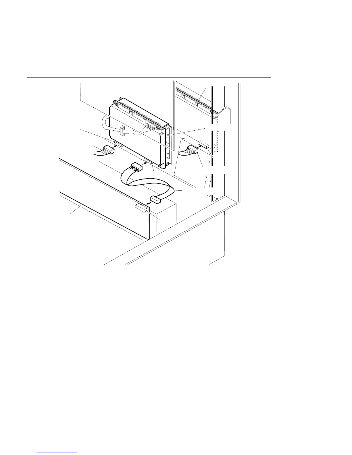
4-26
DVS-7000AE IM
4-4. Installation of Options for Control Panel
(6) Connect the harness (CTRL11) supplied with the control panel between CN2 (12-pin) of the option
panel and CN18 (12-pin) on the CN-1143 board.
(7) Connect the harness (DC12)supplied with the control panel between CN3 (6-pin) of the option panel
and CN4 (6-pin) on the KY-320 board.
(8) Turn on the power switches in the control panel.
(Refer to “4-4-2. Turning On/Off the Power Switch”.)
(9) Close the panel. (Refer to “4-4-1. Opening and Closing of Panel”.)
CN3
CN4
Harness(DC12)
CN2
CN-1143 board
Harness(CTRL11)
Option panel
Harness(DC12)
CN18
KY-320 board
Page 71
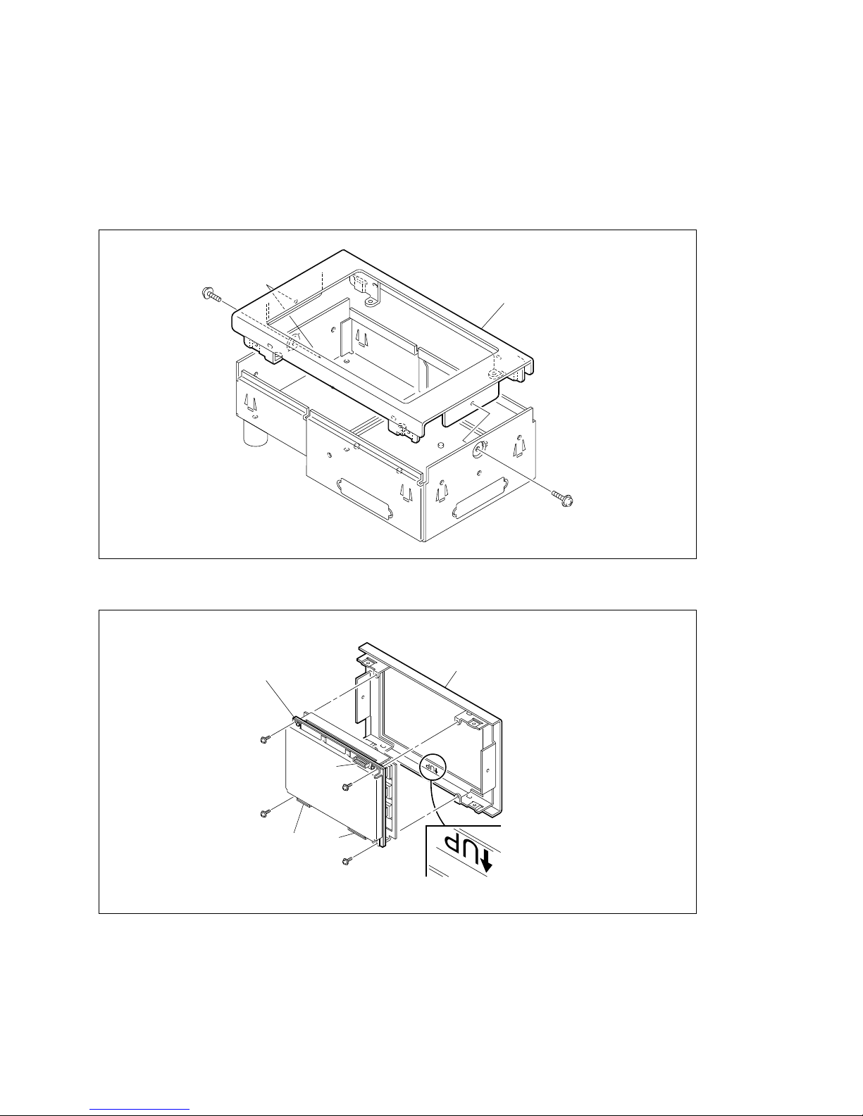
DVS-7000AE IM
4-27
AD panel
B3 x 5
B3 x 5
4-4. Installation of Options for Control Panel
4. Installation to Adaptor Box (BKDS-7075)
(1) Open the panel. (Refer to “4-4-1. Opening and Closing of Panel”.)
(2) Turn off the power switches A and B in the control panel.
(Refer to “4-4-2. Turning On/Off the Power Switch”.)
(3) Remove the two screws and the AD panel.
(4) Secure BKDS-7030 to the AD panel by the supplied four screws (PSW3 x 8).
BKDS-7030/7031/7032
PWH3 x 8
PWH3 x 8
PWH3 x 8
PWH3 x 8
CN3 CN2
CN1
AD panel
Page 72
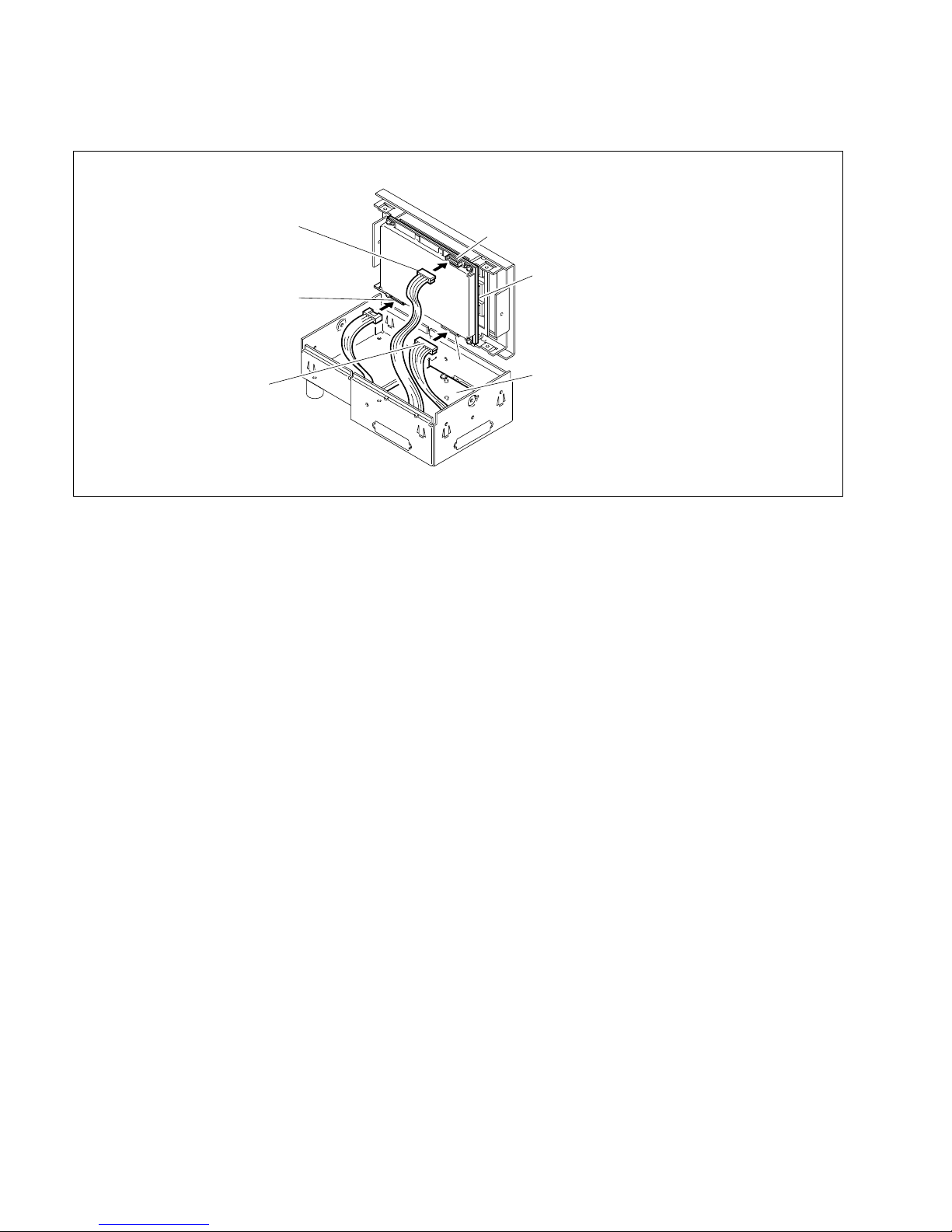
4-28
DVS-7000AE IM
CN1
KY-325/328/329 board
CN2
IF-629 board
Red
CN3
White
4-4. Installation of Options for Control Panel
(5) Connect the three harnesses of the IF-629 board to the CN1 through CN3 on the KY-328 board.
(6) Secure the AD panel to the adaptor box by the two screws.
(7) Turn on the power switches A and B in the control panel.
(If the one power unit is installed, turn on the power switch of the installed power unit.)
(Refer to “4-4-2. Turning On/Off the Power Switch”.)
(8) Close the panel. (Refer to “4-4-1. Opening and Closing of Panel”.)
Page 73
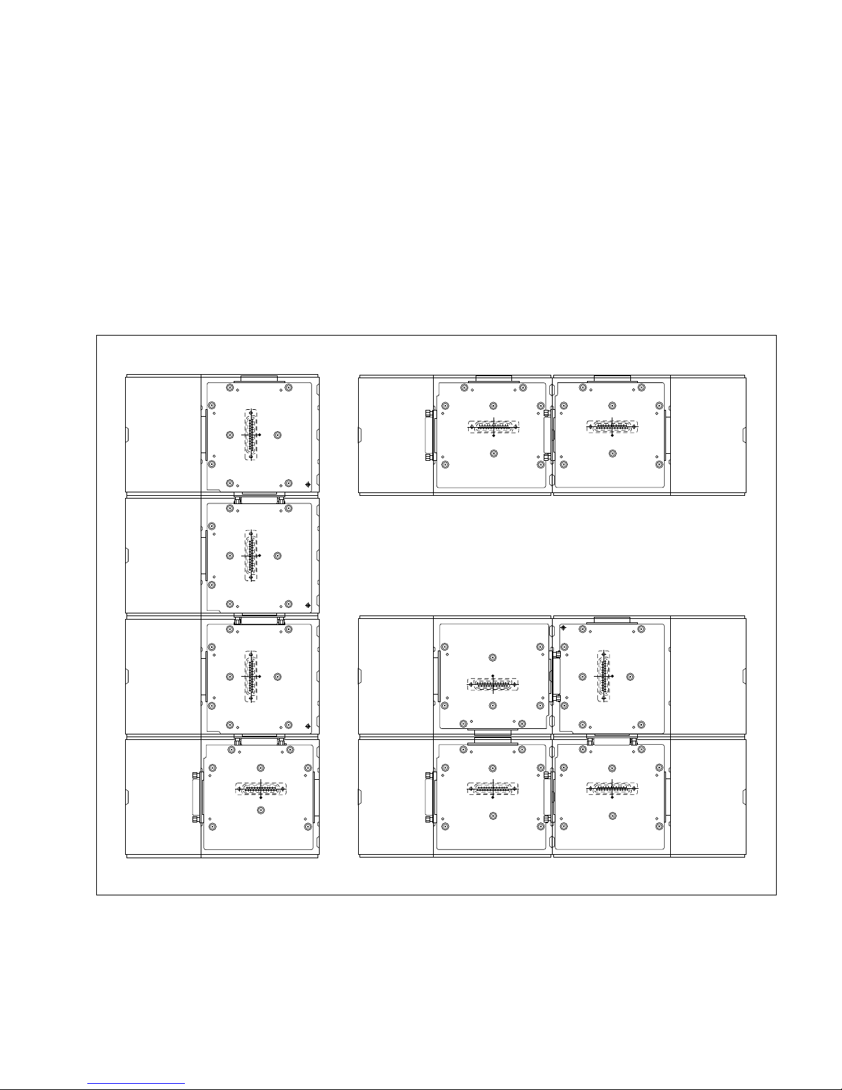
DVS-7000AE IM
4-29
4-4. Installation of Options for Control Panel
4-4-6. Joining of BKDS-7075 (Control Panel Remote Adaptor)
Contents
Adaptor : 1pc
Joint : 2pcs
Joint bracket : 6pcs
Nylon rivet : 2pcs
Screws (B 3 x 5) : 6pcs
BKDS-7075s can be joined the vertical direction, the horizontal direction or the vertical and horizontal
directions as shown in the following figure.
Before joining the BKDS-7075s, reinstall the IF-629 board according to the types (Type-A through -D).
Type-A
Type-C
Type-D
Type-A
Type-B
Type-B
Type-B
Type-A
Type-C
Type-C
Vertical direction
Vertical and horizontal direction
Horizontal direction
Page 74
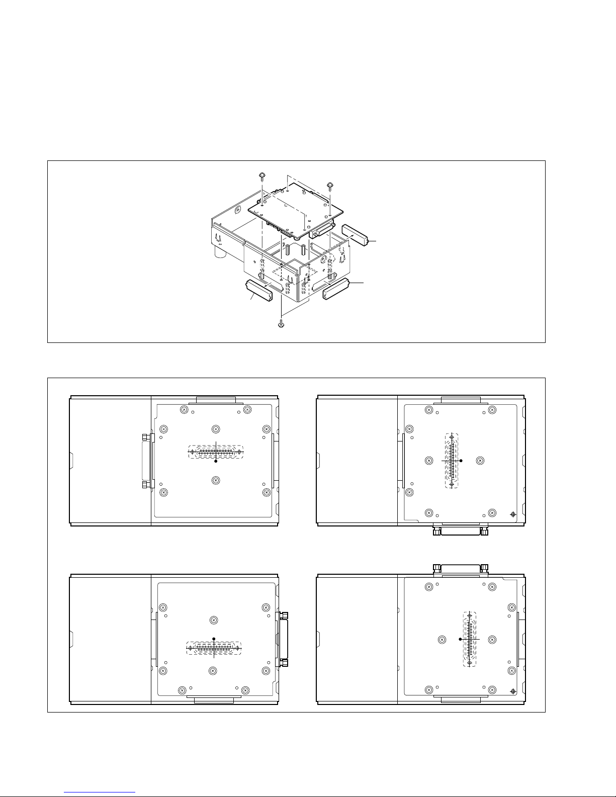
4-30
DVS-7000AE IM
Cap
Cap
Cap
PSW3 x 8
PSW3 x 8
B3 x 5
4-4. Installation of Options for Control Panel
1. Removal and Installation of IF-629 Board
(1) Remove the AD panel.
(Refer to the step (3) of “4. Installation to Adaptor Box (BKDS-7075)” in the section 4-4-5.)
(2) Remove the caps and the IF-629 board.
(Refer to “5. IF-629 Board” in the section 1-2-5 of the maintenance manual part 1.)
(3) Install the IF-629 board according to the type of joining of BKDS-7075s as shown in the following
figure. (Refer to “5. IF-629 Board” in the section 1-2-5 of the maintenance manual part 1.)
(4) Install the caps to the connectors (except CN4) on the IF-629 board.
(5) Install the AD panel to the adaptor box.
(Refer to the step (6) of “4. Installation to Adaptor Box (BKDS-7075)” in the section 4-4-5.)
Type-A (Factory setting)
Type-C
Type-B
Type-D
CN7
CN4 CN8
IF-629 board
CN7
CN8 CN4
IF-629 board
CN8
CN7
IF-629 board
CN4
CN4
CN7
IF-629 board
CN8
Page 75
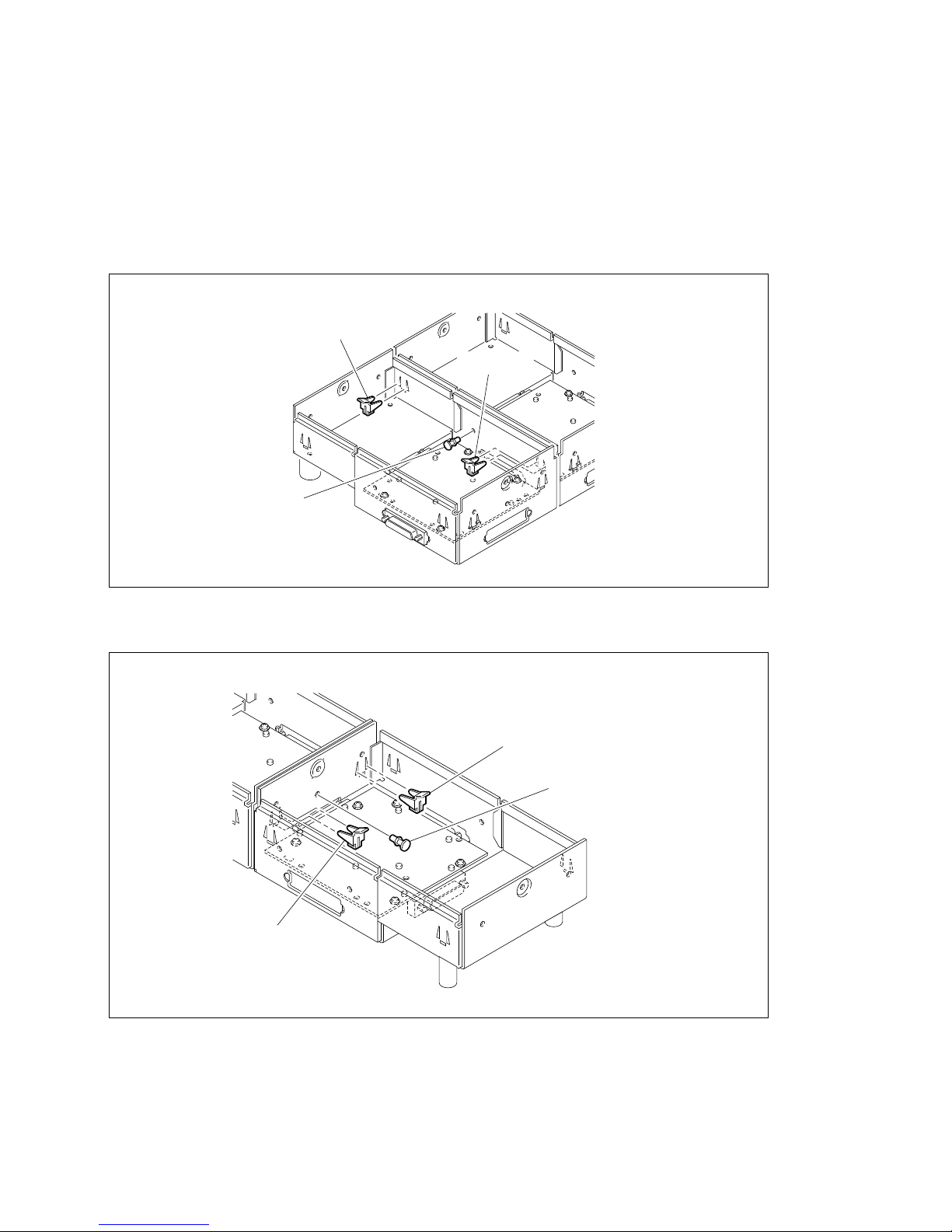
DVS-7000AE IM
4-31
Joint bracket
Nylon rivet
Joint bracket
Joint bracket
Joint bracket
Nylon rivet
4-4. Installation of Options for Control Panel
2. Joining of Adaptor Box (BKDS-7075)
(1) Join the two adaptor boxes (BKDS-7075).
(2) Press in the nylon rivet as shown in the following figure.
(3) Press in the two joint brackets as shown in the following figure.
(In the case of the vertical direction)
(In the case of the horizontal direction)
Page 76
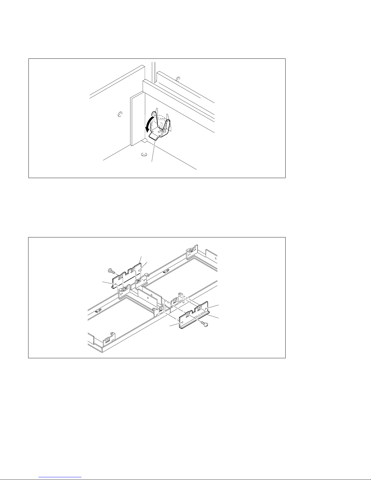
4-32
DVS-7000AE IM
B3 x 5
B3 x 5
Joint
Joint
Boss
Boss
Boss
Boss
4-4. Installation of Options for Control Panel
(4) Lock the two adaptor boxes by pressing down the joint brackets.
3. Joining of AD Panel
In the case of the horizontal direction, join the two AD panels in the following procedures.
(1) Place the two AD panels as shown in the following figure.
(2) Put the bosses of the joint in the holes of the AD panel, and then install the joint to the AD panel by
the two screws.
4. Installation of AD Panel
(1) Install the AD panel to the adaptor box.
(Refer to the step (6) of “4. Installation to Adaptor Box (BKDS-7075)” in the section 4-4-5.)
* In the case of the vertical and horizontal directions, join to the vertical direction after joining to the
horizontal direction.
Joint bracket
Page 77
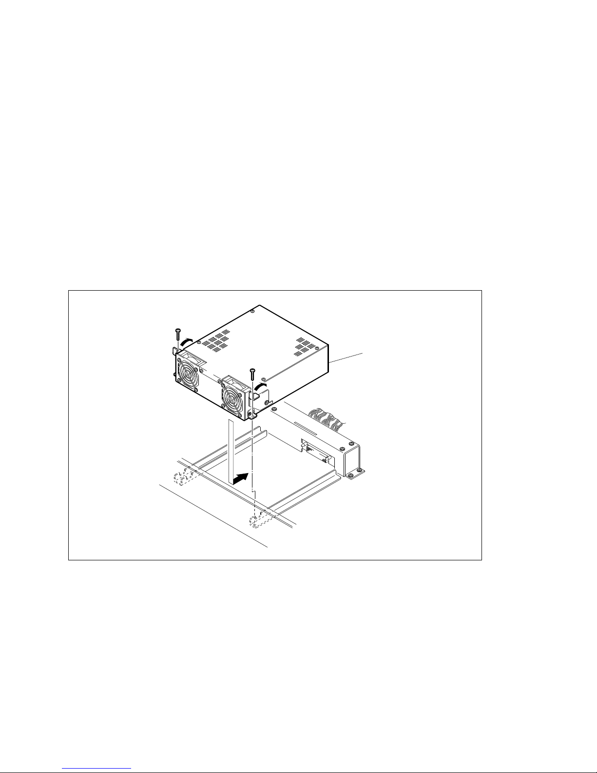
DVS-7000AE IM
4-33
BKDS-7090
PS3 x 6
PS3 x 6
4-4. Installation of Options for Control Panel
4-4-7. Installation of BKDS-7090 (Redundant Power Supply Unit)
w
To avoid shock hazards, be sure to turn off the breaker at the outside of the control panel or unplug the
power cord when installing BKDS-7090.
Contents
Power unit : 1pc
Screw (PS3 x 6): 2pcs
(1) Open the panel. (Refer to “4-4-1. Opening and Closing of Panel”.)
(2) Turn off the power switches in the control panel.
(Refer to “4-4-2. Turning On/Off the Power Switch”.)
(3) Properly insert BKDS-7090 to the pre-install position.
(4) Put the two levers at both sides of BKDS-7090 in the directions of the allows.
(5) Secure BKDS-7090 to the control panel by the two screws (PS3 x 6) supplied with BKDS-7090.
(6) Turn on the power switches in the control panel.
(Refer to “4-4-2. Turning On/Off the Power Switch”.)
(7) Close the panel. (Refer to “4-4-1. Opening and Closing of Panel”.)
Page 78

Page 79
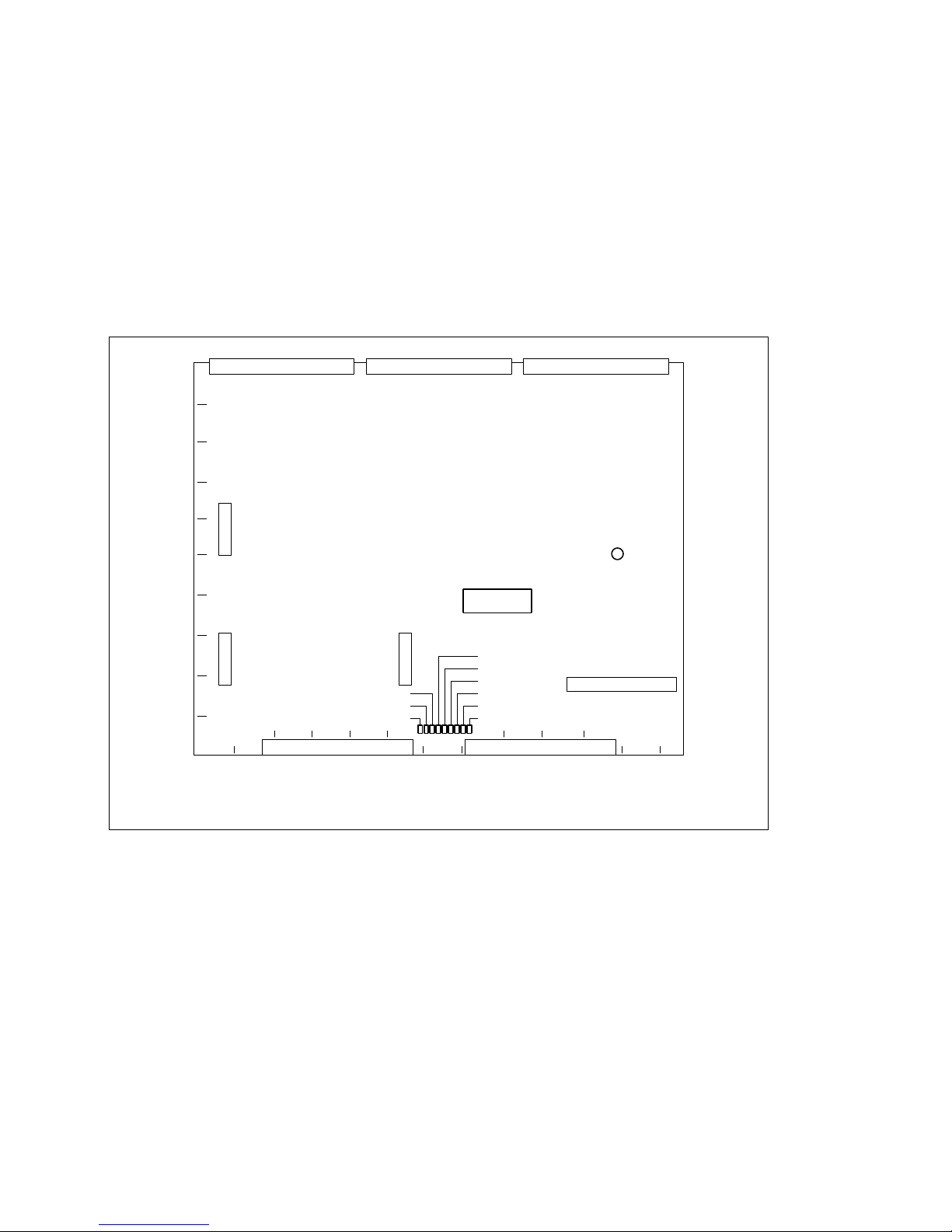
DVS-7000AE IM
5-1
Section 5
Confirmation in Installation
5-1. Switch Settings on Boards and LEDs Description
n
The addresses on the boards are shown by ( ) marks.
5-1-1. DVS-7000A
1. CA-35A Board
CN1 (E8) : FRAME MEMORY BOARD connector
This connector is reserved for future system expansion.
CT501 (F11) : BURST LEVEL adjustment
This potentiometer is used to adjust for the BURST level of the REF OUT.
Not use. This adjustment is finished in the factory.
D506 (Green color) (A6) : REF IN
This LED is displayed that the REF INPUT terminal receives the reference signal or not.
When the REF INPUT terminal receives the reference signal, this LED lights.
D507 (Green color) (A7) : REF OUT BB ON
This LED is displayed that the type of the signal is provided from the REF OUTPUT terminal.
Light; The 525 line black burst signal is provided from the REF OUTPUT terminal.
Light off; The sync signal is provided from the REF OUTPUT terminal.
CN1
CT501
A
12
3 4 5 6 8 9 10 11
71213
B
C
D
E
F
G
H
J
K
CA-35A board
D509
D510
D513
D9
D23
D24
D508
D507
D506
(Component side/A side)
Page 80

5-2
DVS-7000AE IM
5-1. Switch Settings on Boards and LEDs Description
D508 (Yellow color) (A7) : D1/D2 lamp
This LED is displayed that the SYSTEM is selected into the D1 or D2 format. This LED lights that the
SYSTEM is selected into the D1 format.
D509 (Yellow color) (A7) : 625/525
This LED is displayed that the SYSTEM is selected into the 525 or 625 line mode. This LED lights that
the SYSTEM is selected into the 625 line mode.
D510 (Red color) (A7) : REF ERR
This LED is displayed that the status of the reference signals are provided to the REF INPUTs terminals.
When the REF INPUTs terminals are not received the reference signals or the received reference signals
are abnormal, this LED lights.
In combination with the REF ERR and REF IN, this LED can check that the status of the reference input
signals.
REF IN (D506) Light Light off
REF ERR (D510)
Light The reference signal is abnormal. The reference signal is not provided.
Light off The normal reference signal is provide. _
D513 (Green color) (A7) : SCH
This LED is displayed that the SCH phase of the black burst signals are provided to the REF INPUTS
signals. When the SCH phase is normal, this LED lights.
D9 (Green color) (A7) : _5 V
This LED is displayed the status of the _5 V source for the CA-35A board.
Light ; Normal status.
Light off ; The power does not provide to the CA-35A board.
D23 (Yellow color) (A7) : +5 V
This LED is displayed the status of the +5 V source for the CA-35A board.
Light ; Normal status.
Light off ; The power does not provide to the CA-35A board.
D24 (Yellow color) (A8) : +3 V
This LED is displayed the status of the +3 V source for the CA-35A board.
Light ; Normal status.
Light off ; The power does not provide to the CA-35A board.
Page 81
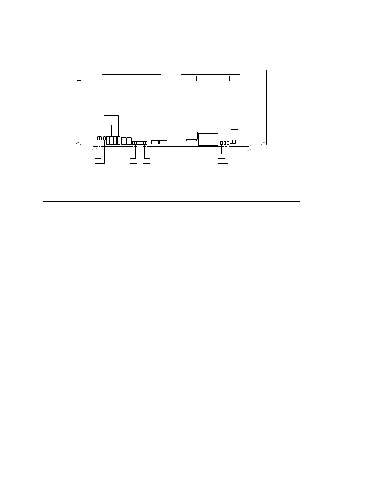
DVS-7000AE IM
5-3
5-1. Switch Settings on Boards and LEDs Description
2. CPU-264 Board
CNT3 (B5) : +5 V TEST terminal
This terminal is used to measure the +5 V voltage.
When re-adjusting the voltage after installing the option board to the unit, this terminal is used.
CNT4 (B5) : +3 V TEST terminal
This terminal is used to measure the +3 V voltage.
When re-adjusting the voltage after installing the option board to the unit, this terminal is used.
CNT6 (C5) : _5 V TEST terminal
This terminal is used to measure the _5 V voltage.
When re-adjusting the voltage after installing the option board to the unit, this terminal is used.
CNT7 (C5) : GND TEST terminal
This terminal is the reference against the +5 V, +3 V and _5 V TEST terminals.
CN8 (G5) : LAN connector
This connector is used for the adjustment in the factory.
CN9 (H5) : TERMINAL connector
This connector complies with the RS-232C standard, and is connected to the control terminal for the
adjustment in the factory and the maintenance.
D15
D16
D18
D1
D2
D3
D4
D8
D7
D6
D5
D14
D12
D13
CNT7
CNT6
CNT4
CNT3
D100
D101
S1
1
AF L
BCD E GHJ K
2
3
4
5
CN8
CN9
S2
S3
S4
CPU-264 board
(Component side/A side)
Page 82

5-4
DVS-7000AE IM
5-1. Switch Settings on Boards and LEDs Description
D1 through D8 (Green colors) (D5/E5) : STATUS displays
These LEDs are used for the adjustment in the factory.
D15 (Yellow color) (B5) : +5 V
This LED is displayed the status of the +5 V source for all system.
Light ; Normal status.
Light off ; The power does not provide to the CPU-264 board or the fuse on the CPU-264 or CA-35A
board blows.
D16 (Yellow color) (B5) : +3 V
This LED is displayed the status of the +3 V source for all system.
Light ; Normal status.
Light off ; The power does not provide to the CPU-264 board or the fuse on the CPU-264 or CA-35A
board blows.
D18 (Green color) (B5) : _5 V
This LED is displayed the status of the _5 V source for all system.
Light ; Normal status.
Light off ; The power does not provide to the CPU-264 board or the fuse on the CPU-264 or CA-35A
board blows.
D14 (Yellow color) (J5) : VD
When the VD signal provides at regular intervals from the CA-35A board and is normal operated, this
LED lights.
D12 (Green color) (J5) : RUN
When the CPU is normal operated, this LED lights.
D13 (Red color) (J5) : FAIL
When the CPU is stopped by some source, this LED lights.
S3 (K5) : ABORT switch
This switch is used when the unit starts up in the factory settings (except for the D1/D2 format and the
RESUME mode).
The unit is operated the same as the clear command of the SET UP menu.
S4 (K5) : RESET switch
This switch is used to forcefully restart the SYSTEM by the hardware.
The unit is operated the same as the operation when turning the POWER ON.
The resume function is not operated.
S1 and S2 (E5) and (F5) : DBG switch
This switch is a 8-pin dip switch and is used to adjust in the factory.
Settings under normal status : All OFF
D100 and D101 (C5) and (D5) : 7 SEGMENT displays
Light off; The power is turned ON.
Display the figure; The application starts the operation.
These figures differ according to the operation mode.
Page 83
DVS-7000AE IM
5-5
5-1. Switch Settings on Boards and LEDs Description
3. RE-110 Board (BKDS-7690)
RV201 (K4) : +5 V (A) adjustment
RV202 (K4) : +5 V (B) adjustment
RV203 (K5) : +3 V adjustment
RV204 (K5) : _5 V adjustment
4. XPT-16 Board
CNT1 (C1) : +5 V TEST terminal
This terminal is used for the measurement of the +5 V voltage.
When re-adjusting the voltage after installing the option board to the unit, this terminal is used.
CNT2 (C1) : +3 V TEST terminal
This terminal is used for the measurement of the +3 V voltage.
When re-adjusting the voltage after installing the option board to the unit, the terminal on the CPU-264
board is used.
CNT3 (D1) : GND TEST terminal
This terminal is used for the reference against the +5 V and +3 V TEST terminals.
CN201
CN202
CN203
CN204
RV201
RV202
RV203
RV204
CN205
CN206
CN207
CN208
CN210
RE-110 board
(Component Side/A Side)
CNX1
CNY1
CNZ1
CNT1
CNT2
CNT3
XPT-16 board
(Component Side/A Side)
Page 84
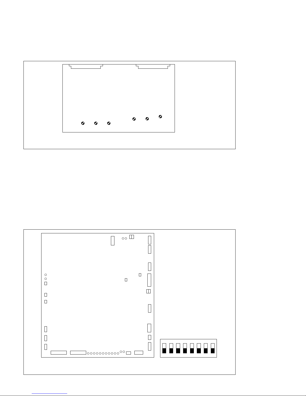
5-6
DVS-7000AE IM
5-1. Switch Settings on Boards and LEDs Description
5-1-2. BKDS-7133
1. ADC-22 Board
CV100 (D2) : CH1 G/Y frequency response adjustment
CV200 (F2) : CH1 B/B-Y frequency response adjustment
CV300 (H2) : CH1 R/R-Y frequency response adjustment
CV500 (K3) : CH2 G/Y frequency response adjustment
CV600 (M3) : CH2 B/B-Y frequency response adjustment
CV700 (P3) : CH2 R/R-Y frequency response adjustment
5-1-3. Control Panel
1. CPU-263 Board
CV100 CV200 CV300
CV500 CV600
CV700
CNX1 CNY1
ADC-22 board
(Component Side/A Side)
ON
12345678
Factory setting
S4, S5
S4
CN6
CN7
CN5
CN4
CN16
COP1
CN11
CN3
S5
CN1
CN8
CN10CN9
CN17
CN18
S3
S2
D1
D2
D102
D112
D7
D6
D111
D101
D295
D27
D26
D25
D24
D23
D22
D21
D20
D19
D18
D17
D16
CN21
S1
COP2
CPU-263 board
(Component Side/A Side)
Page 85
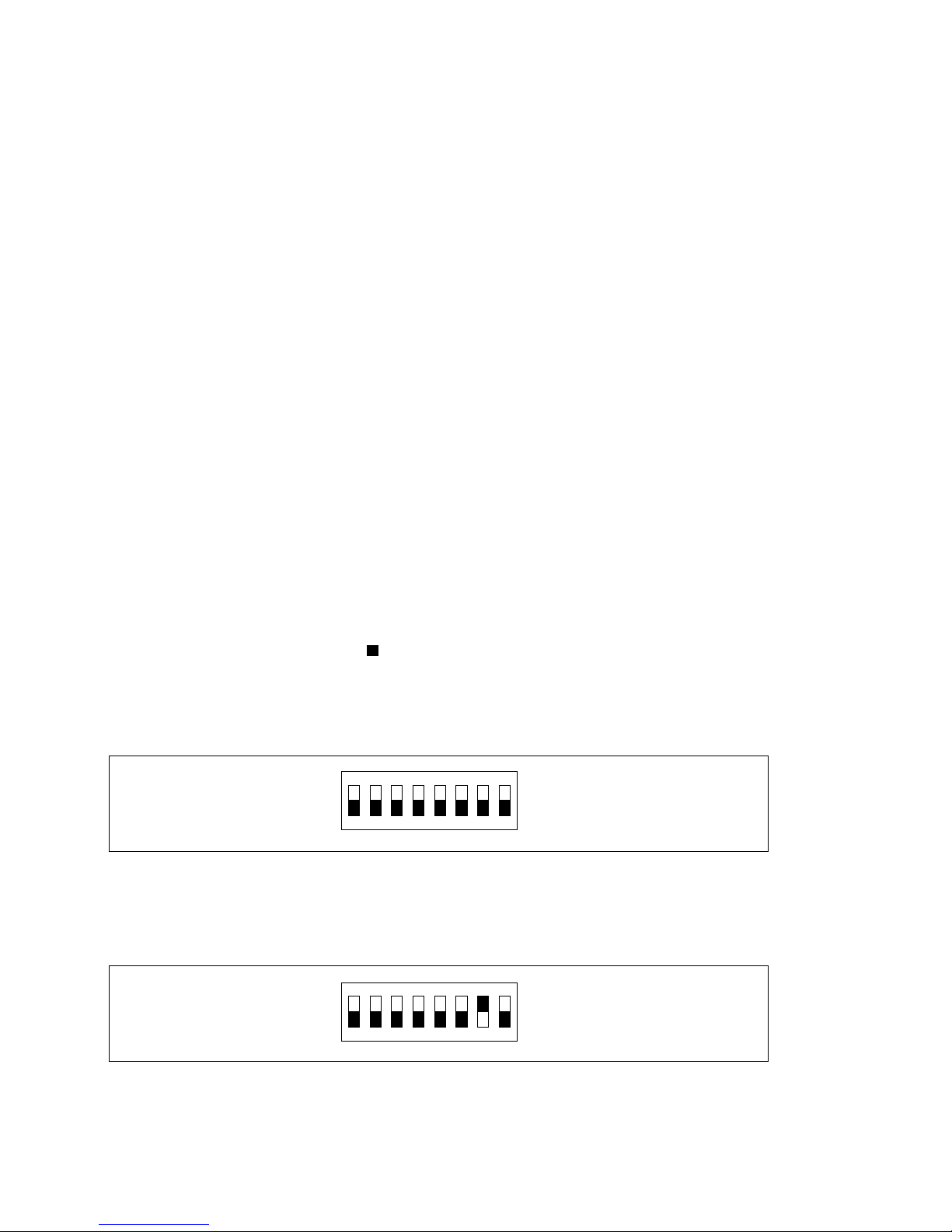
DVS-7000AE IM
5-7
5-1. Switch Settings on Boards and LEDs Description
COP1 (F2) :
This is used to select the mode corresponding to the synchronized signal that is connected to the
SWITCHER on the rear panel. Normaly, opened under.
COP2 (G3) :
Normaly, short-circuit the “NOR” side.
S1 (G12) : RESET switch
This switch is used to forcibly restart the SYSTEM by the hardware. The unit is operated the same as the
operation when turning the POWER ON.
S2 (H12) : ABORT switch
This switch is used for the adjustment in the factory.
S3 (J12) : SUB ABORT switch
This switch is used for the adjustment in the factory. If pressing this switch after selecting the S5 switch
on the CPU-263 board to the SUB CPU flash memory access protection mode, clean the content of the
flash memory for stored-program.
S4 (B5) : MAIN CPU switch
This switch is used to select the operation of MAIN CPU. After changing the selection, to start the
operation re-press the S1 of the RESET switch on the CPU-263 board or re-turn the power on.
Setting : All OFFs.
n
The addresses of the knobs are shown by marks.
(1) Selection 1 under normal status
When starting up the system, the diagnostic program does not run. Just after turning the power on,
the system starts up.
(2) Selection 2 under normal status.
When starting up the system, diagnostic program runs. After turning the power on, it is necessary for
about ten seconds until the system starts up.
Under normal status, all settings are OFFs.
ON
12345678
ON
12345678
Page 86
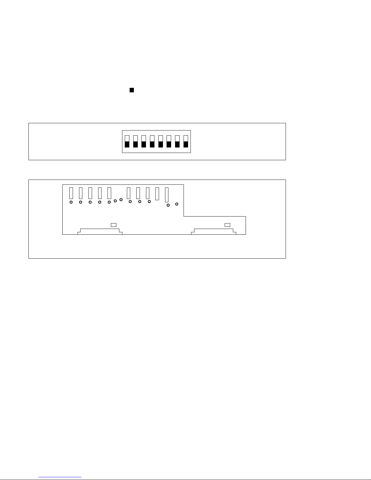
5-8
DVS-7000AE IM
S5 (M1) : SUB CPU switch
This switch is used to select the operation mode of SUB CPU.
Selections in the factory : All OFF
n
The addresses of the knobs are shown by marks.
(1) Selections when operating under normal status
The selections for normal operation.
2. CN-1148 Board
D1 (Green color) (F2) :
When the +5 V source provides to the CN11 on the CN-1148 board, this LED lights.
D2 (Yellow color) (F2) :
When the +12 V source provides to the CN12 on the CN-1148 board, this LED lights.
D4 (Red color) (F2) :
When the +3 V source provides to the CN13 on the CN-1148 board, this LED lights.
D5 (Red color) (D2) :
When the +3 V source provides to the CN14 on the CN-1148 board, this LED lights.
D6 (Red color) (D2) :
When the +3 V source provides to the CN15 on the CN-1148 board, this LED lights.
D7 (Red color) (C2) :
When the +3 V source provides to the CN16 on the CN-1148 board, this LED lights.
5-1. Switch Settings on Boards and LEDs Description
ON
12345678
CN2
CN4
CN1
CN3
CN-1148 board
CN12
D2
D1
D4
D5
D6
D12
D13
D7
D8
D9
D10
D11
CN11
CN13
CN14
CN15
CN16
CN17
CN18
CN19
CN20
(Component Side/A Side)
Page 87
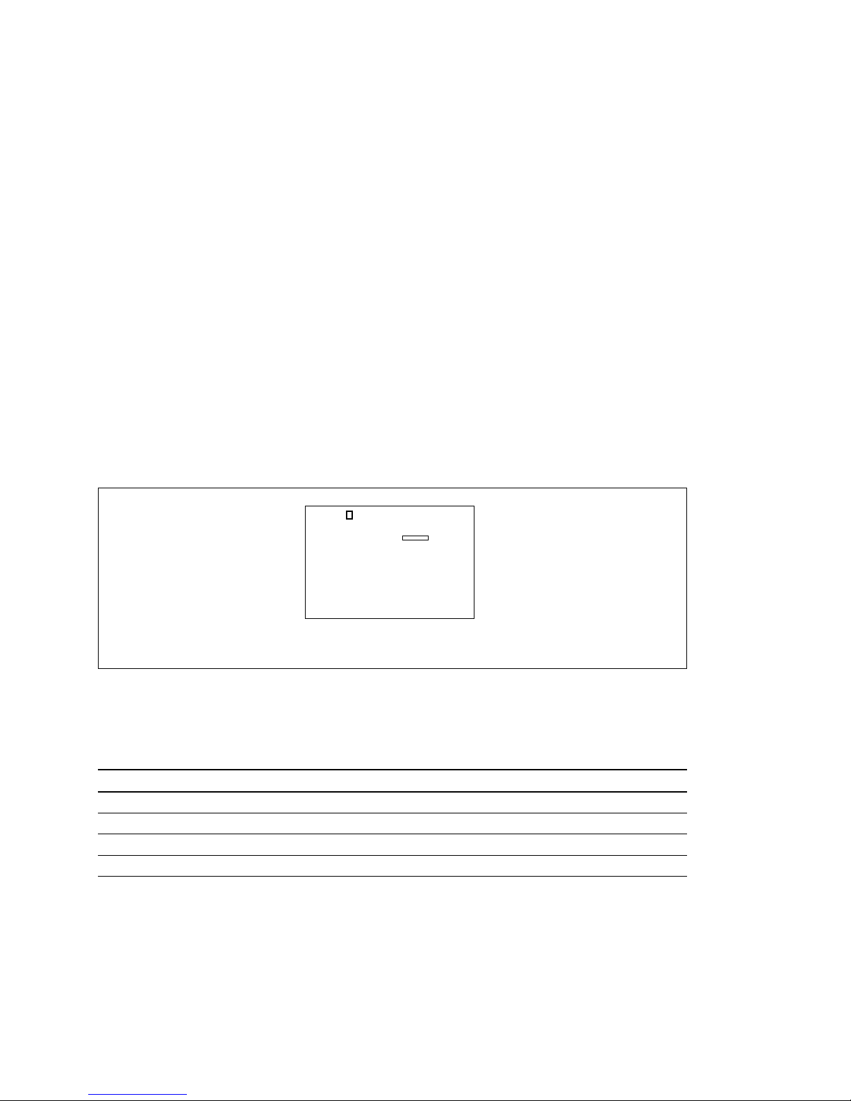
DVS-7000AE IM
5-9
S1
CN5
KY-318 board
(Component Side/A Side)
5-1. Switch Settings on Boards and LEDs Description
D8 (Red color) (D2) :
When the +3 V source provides to the CN17 on the CN-1148 board, this LED lights.
D9 (Red color) (B2) :
When the +3 V source provides to the CN18 on the CN-1148 board, this LED lights.
D10 (Red color) (A2) :
When the +3 V source provides to the CN19 on the CN-1148 board, this LED lights.
D11 (Red color) (A2) :
When the +3 V source provides to the CN20 on the CN-1148 board, this LED lights.
D12 (Yellow color) (C1) :
When the +12 V source provides to the CN13 through CN20 on the CN-1148 board, this LED lights.
D13 (Green color) (C1) :
When the +5 V source provides to the CN13 through CN20 on the CN-1148 board, this LED lights.
3. KY-318 Board
S1 (C1) : Board ID Setting Switch
Set this switch as follows depending upon the M/E row position in which the KY-318 board is installed.
Normally, use the default settings when shipped from the factory.
Factory settings :
Row position Ch.1 Ch.2
M/E-1 OFF ON
M/E-2 ON OFF
M/E-3 OFF OFF
P/P ON ON
Page 88
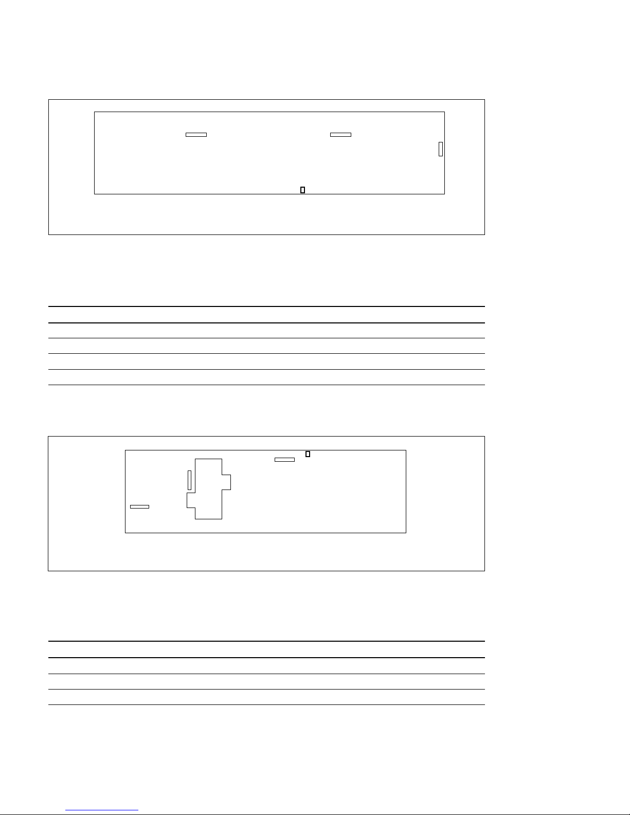
5-10
DVS-7000AE IM
KY-319 board
CN6 CN5
S1
CN7
(Component Side/A Side)
5-1. Switch Settings on Boards and LEDs Description
4. KY-319 Board
S1 (R4) : Board ID Setting Switch
Set this switch as follows depending upon the M/E row position in which the KY-319 board is installed.
Normaly, use the default settings when shipped from the factory.
Factory settings:
Row position Ch.1 Ch.2
M/E-1 OFF ON
M/E-2 ON OFF
M/E-3 OFF OFF
P/P ON ON
5. KY-320 Board
S1 (N1) : Board ID Setting Switch
Set this switch as follows depending upon the M/E row position in which the KY-320 board is installed.
Normaly, use the default settings when shipped from the factory.
Factory settings:
Row position Ch.1 Ch.2
M/E-1 OFF ON
M/E-2 ON OFF
M/E-3 OFF OFF
CN6
CN7
CN8
S1
KY-320 board
(Component Side/A Side)
Page 89
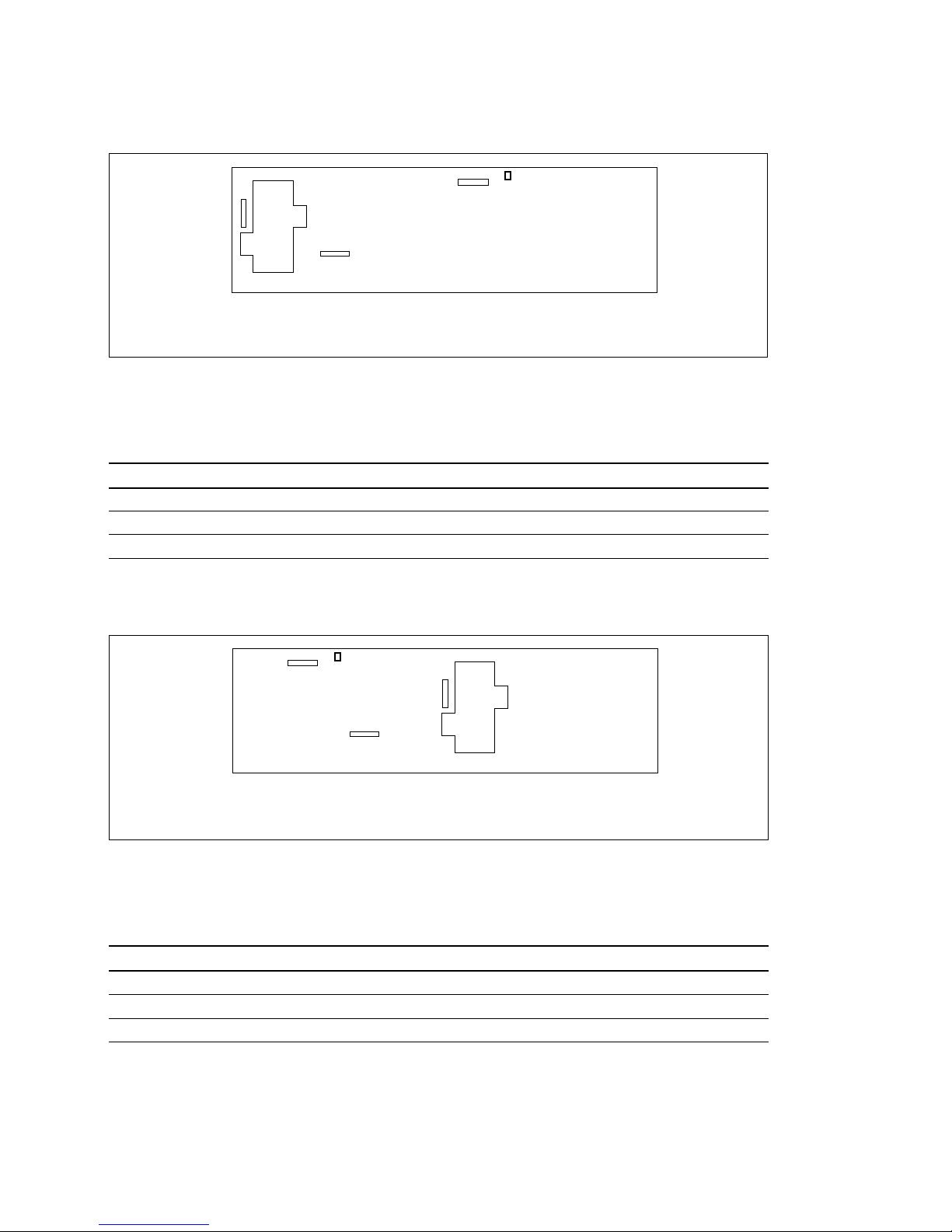
DVS-7000AE IM
5-11
CN6
CN7
CN8
S1
KY-367 board
(Component Side/A Side)
CN6
CN7
CN8
S1
KY-321 board
(Component Side/A Side)
5-1. Switch Settings on Boards and LEDs Description
6. KY-321 Board (BKDS-7011/7021/7023/7011R/7021R/7023R/7011LR/7021LR/7023LR)
S1 (N1) : Board ID Setting Switch
Set this switch as follows depending upon the M/E row position in which the KY-321 board is installed.
Normaly, use the default settings when shipped from the factory.
Factory settings:
Row position Ch.1 Ch.2
M/E-1 OFF ON
M/E-2 ON OFF
M/E-3 OFF OFF
7. KY-367 Board (BKDS-7012/7022/7022R/7022LR)
S1 (F1) : Board ID Setting Switch
Set this switch as follows depending upon the M/E row position in which the KY-367 board is installed.
Normaly, use the default settings when shipped from the factory.
Factory settings:
Row position Ch.1 Ch.2
M/E-1 OFF ON
M/E-2 ON OFF
M/E-3 OFF OFF
Page 90
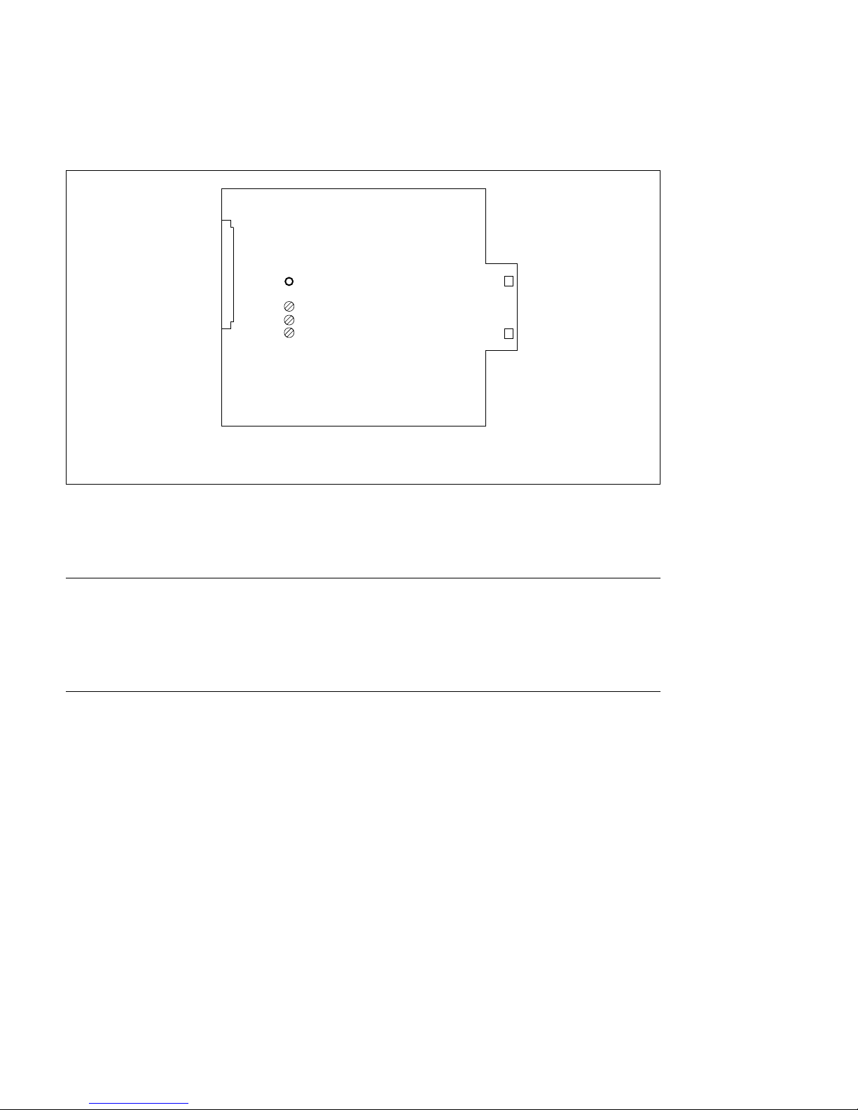
5-12
DVS-7000AE IM
RV2
D9
RV1
RV3
CN5
CN6
CN4
RE-112 board
(Component Side/A Side)
5-1. Switch Settings on Boards and LEDs Description
5-1-4. BKDS-7090
1. RE-112 Board
D9 (Green color) (C4) :
When the power is normal operated, this LED lights.
When the following troubles come up, this LED light off.
In the cases that one power unit is used.
1. When the power switch in the panel is turned off.
2. When the fun stops in the power unit.
3. When the CP1 or CP2 in the power unit is not normal operated.
In the cases that two power units are used.
1. When the one power switch in the panel is turned off.
2. When the one fun stops in the power unit.
3. When the CP1, CP2, CP3 or CP4 in the power unit is not normal operated.
4. When the voltage of the two power is correctly adjusted.
(The diode on the power unit that is low-level lights off.)
In the steps 1 through 3, the diode on the power unit that is not normal operated lights off.
RV1 (C5) : +5 V voltage adjustment
RV2 (C4) : +12 V voltage adjustment
RV3 (C5) : +3 V voltage adjustment
Page 91

DVS-7000AE IM
5-13
5-2. Adjustment of Secondary Power Supply Voltage
5-2-1. DVS-7000A
DVS-7000A has the power sources of +5 V (A), +5 V (B), +3 V, and _5 V. For the voltage
measurement of +5 V (A), +3 V, and _5 V and on the CPU-264 board and +5 V (B)or XPT-16 board the
test terminals are provided that can be connected to the probe of a digital voltmeter.
After installation of all required plug-in boards is completed, confirm the power supply voltage in the unit
as described below.
n
Confirm that the power unit is properly inserted and secured by the four screws.
When only standard power unit is installed, refer to the following procedures for power
unit A.
This standard power unit is named as power unit A
(Procedures for Power Unit A)
(1) Detach the front panel of DVS-7000A.
(Refer to “4-3-1. Detaching and Attaching of Front Panel”)
(2) Turn on the power switch of the power unit A.
(3) Confirm that all indicators (D15, D16 and D18) on the CPU-264 board light.
(4) Connect the digital voltmeter between test terminals on the CPU-264 and the XPT-16 boards and
confirm that the voltage value of each test connector meet the specification shown in the table below.
If the specification does not meet, adjust the voltage by the adjustment potentiometers of the power
unit A.
n
When connecting the probes of the digital voltmeter between test terminals, take care to avoid
contacting the probes with the GND areas of the shield plates.
When the power unit BKDS-7690 is installed, refer to the following procedures for power
unit B.
The power unit of BKDS-7690 is named as power unit B.
(Procedures for Power Unit B)
(1) Turn off the power switch of the power unit B.
(2) Carry out all steps of “procedures for power unit A”.
(3) Turn off the power switch of the power unit A and turn on the power switch of the power unit B.
(4) Confirm that all indicators (D15, D16 and D18) on the CPU-264 board light.
5-2. Adjustment of Secondary Power Supply Voltage
Page 92
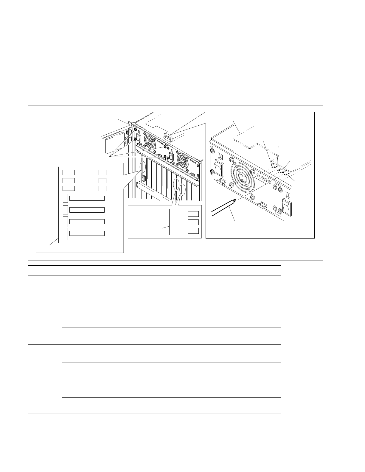
5-14
DVS-7000AE IM
5-2. Adjustment of Secondary Power Supply Voltage
(5) Connect the digital voltmeter between test terminals on the CPU-264 and the XPT-16 boards and
confirm that the voltage value of each test connector meet the specification shown in the table below.
If the specification does not meet, adjust the voltage by the adjustment potentiometers of the power
unit B.
(6) Turn on the power switches of the power units A and B.
(7) Confirm that the indicators of the power units A and B light. If an indicator of both does not light, re-
carry out from the step (1) of “procedures for power unit B”.
Power unit Voltage Specifications Test connector Adjustment potentiometer
A +5 V (A) +5.05 ± 0.02 V CPU-264 board RE-110 board
CNT3 (+5 V)
→
→
CNT7 (GND) 1RV201 (Power unit A)
+5 V (B) +5.05 ± 0.02 V XPT-16 board RE-110 board
CNT1 (+5 V)
→
→
CNT3 (GND) 1RV202 (Power unit A)
+3 V +3.35 ± 0.02 V CPU-264 board RE-110 board
CNT4 (+3 V)
→
→
CNT7 (GND) 1RV203 (Power unit A)
_5 V _5.05
+0.00 V (*1)
CPU-264 board RE-110 board
_0.02 V
CNT6 (_5 V)
→
→
CNT7 (GND) 1RV204 (Power unit A)
B +5 V (A) +5.05 ± 0.02 V CPU-264 board RE-110 board
CNT3 (+5 V)
→
→
CNT7 (GND) 1RV201 (Power unit B)
+5 V (B) +5.05 ± 0.02 V XPT-16 board RE-110 board
CNT1 (+5 V)
→
→
CNT3 (GND) 1RV202 (Power unit B)
+3 V +3.35 ± 0.02 V CPU-264 board RE-110 board
CNT4 (+3 V)
→
→
CNT7 (GND) 1RV203 (Power unit B)
_5 V _5.03
+0.02 V (*2)
CPU-264 board RE-110 board
_0.00 V
CNT6 (_5 V)
→
→
CNT7 (GND) 1RV204 (Power unit B)
(*1) For the power unit A the center value of the _5 V is _5.05 V.
(*2) For the power unit B the center value of the _5 V is _5.03 V.
PWH4 x 8
RV201
+5 V (A)
RV202
+5 V (B)
RV203
+3 V
RV204
_5 V
CNT1
CNT2
CNT3
5V
3V
_5V
CNT3
CNT4
CNT6
5V 3V _5V
CNT7
GND
D15 (B5)
D16 (B5)
D18 (B5)
RE-110 board
Power supply unit
Adjustment driver
XPT-16 board
CPU-264 board
Page 93

DVS-7000AE IM
5-15
5-2. Adjustment of Secondary Power Supply Voltage
5-2-2. Control Panel
The control panels have the power sources of +5 V, +3 V and +12 V.
For the voltage measurement of +5 V, +3 V and +12 V, on the CN-1148 board the test terminals are
provided that can be connected to the probe of a digital voltmeter.
After installation of all required options is completed, confirm the power supply voltage in the unit as
described below.
n
Confirm that the power unit is properly inserted and secured by the two screws.
When only standard power unit is installed, refer to the following procedures for power
unit A.
The standard power unit is named as power unit A.
(Procedures for Power Unit A)
(1) Open the panel. (Refer to “4-4-1. Opening and Closing of Panel”.)
(2) Turn on the power switch A of the power unit A.
(3) Confirm that the indicators (D1, D2 and D4 through D13) on the CN-1148 board light.
(4) Connect the digital voltmeter between test connectors on the CN-1148 board and confirm that the
voltage value meets the specification shown in the table below.
If the specification does not meet, adjust the voltage by the adjustment potentiometer of the power
unit A.
When the power unit of BKDS-7090 is installed, refer to the following procedures for
power unit B.
This power unit of BKDS-7090 is named as power unit B.
(Procedures for Power Unit B)
(1) Turn OFF the power switch B of the power unit B.
(2) Carry out all steps of “procedures for power unit A”.
(3) Turn OFF the power switch A of the power unit A and turn ON the of the power switch B of the
power unit B.
(4) Confirm that the indicators (D1, D2 and D4 through D13) on the CN-1148 board lights.
Page 94
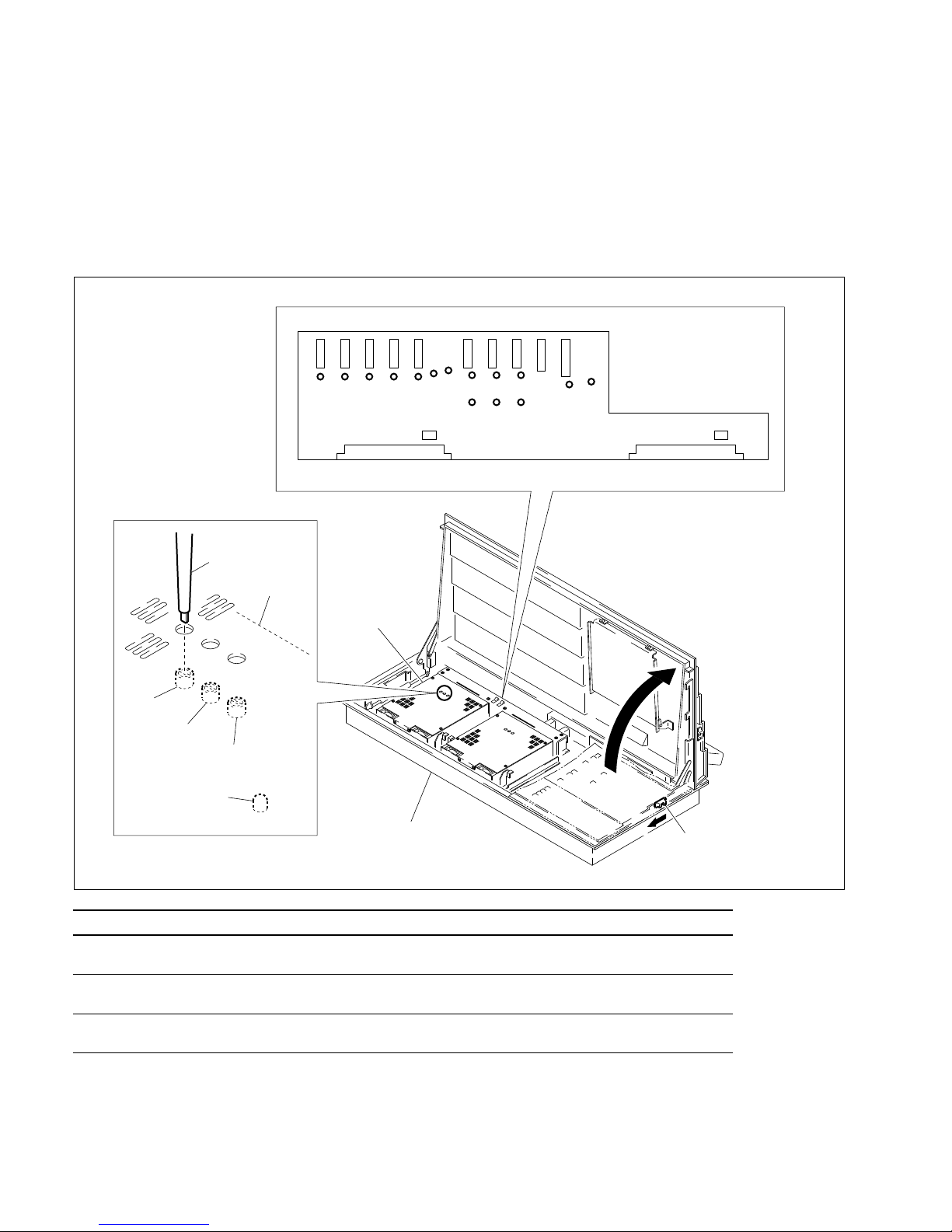
5-16
DVS-7000AE IM
5-2. Adjustment of Secondary Power Supply Voltage
(5) Connect the digital voltmeter between test terminals on the CN-1148 board and confirm that the
voltage value meets the specification shown in the table below.
If the specification does not meet, adjust the voltage by the adjustment potentiometer of the power
unit B.
(6) Turn ON the power switches A and B of the power units A and B.
(7) Confirm that the indicators of the power units A and B light. If an indicator of both does not light, re-
carry out from the step (1) of “procedures for power unit B”.
Voltage Specifications Test connector Adjustment potentiometer
+5 V +5.10 ± 0.02 V CN-1148 board RE-112 board
TP1 (+5 V)
→
→
E1 (GND) 1RV1
+3 V +3.10 ± 0.02 V CN-1148 board RE-112 baord
TP3 (+3 V)
→
→
E1 (GND) 1RV3
+12 V +12.24 ± 0.02 V CN-1148 board RE-112 board
TP2 (+12 V)
→
→
E1 (GND) 1RV2
BKDS-7011/7021/7022
Slide knobs (Left/Right)
A
Power supply unit
RV3
+3 V
RV1
+5 V
RV2
+12 V
Adjustment driver
RE-112 board
CN2
CN4
CN1
CN3
CN-1148 board (A side)
CN12
D2
D1
D4
D5
D6
TP3
TP2
TP1
D12
D13
D7
D8
D9
D10
D11
CN11
CN13
CN14
CN15
CN16
CN17
CN18
CN19
CN20
D9
Page 95
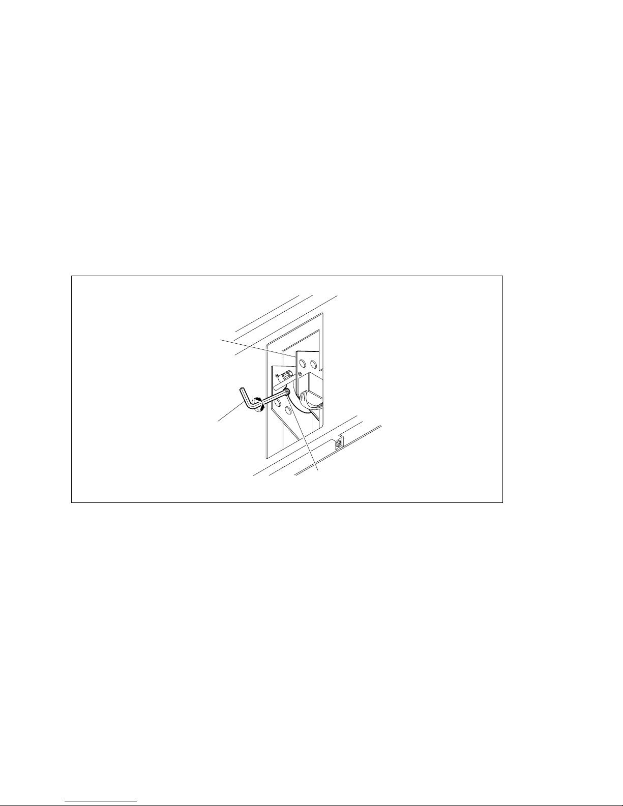
DVS-7000AE IM
5-17
5-3. Adjustment of Operation Power for Fader Lever
5-3. Adjustment of Operation Power for Fader Lever
Without removing the fader from the panel, the operation power of the fader lever is possible to adjust.
(1) Open the panel. (Refer to “4-4-1. Opening and Closing of Panel”.)
(2) When adjusting the fader lever (BKDS-7030) with installed to the adaptor box (BKDS-7075), remove
the two screws and the AD panel.
(Refer to “3. Adaptor Box” in the section 1-2-3 of the maintenance manual part 1.)
When adjusting the fader lever in the main panel, remove the CPU-263 board.
(Refer to “3. CPU-263 Board” in the section 1-2-5 of the maintenance manual part 1.)
(3) Turn the screw by an L wrench (across 4.0 mm) and adjust the operation power.
2 : If turning the screw clockwise, the operation of the fader lever become slow.
3 : If turning the screw counterclockwise, the operation of the fader lever become fast.
Fader assy
Hexagon wrench (4.0 mm)
Screw
Page 96

Page 97

DVS-7000AE IM
6-1
Section 6
Initial Set-up of System
Before setting-up for DVS-7000A, the installation of operating program, the set-up required in the
construction of the system and the saving of set-up data for DVS-7000A system are described.
6-1. Operation and Saving of Set-up Data
This section is described the operation and the saving of the set-up data in the system.
A set-up data exists in the four domains shown as follows.
1. RAM
This memory is the operating domain. The system operates using the set-up data on this memory. The
set-up data is always changed on this memory.
When the resume function is selected to the OFF, by turning the power OFF or by resetting the system the
set-up data on this memory is lost.
After turning the power ON or resetting the system, the set-up data in the Nonvolatile memory is recalled
on this RAM.
When the resume function is selected to the ON, regardless of the turning the power OFF or resetting
system, the system operates using the set-up data on this memory.
2. Nonvolatile Memory
This is a nonvolatile memory. If turning the power OFF, this memory can save the data. This memory is
used as the saving domain of the back up data when the resume function is selected to the OFF.
3. ROM
This memory permanently saves the basic set-up data in the factory shipment. When the system is reset
up or the nonvolatile memory is initialized, this memory is used.
If calling the contents, initialize the system in the set-up menu screen.
4. DISK
A disk is used to more permanently save the set-up data saved in the nonvolatile memory, to transfer the
set-up data to another editing suite, or to keep the data for oneself by operator.
Page 98
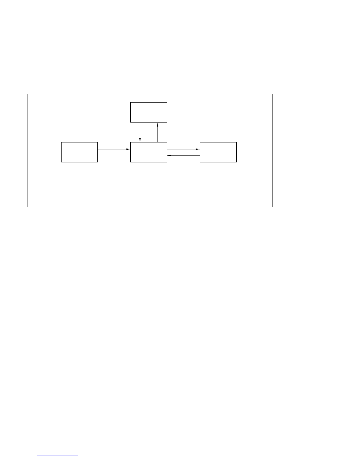
6-2
DVS-7000AE IM
6-1. Operation and Saving of Set-up Data.
n
The following data are saved the status that is displayed on the menu screen and are
not changed by resetting or all-clearing the system.
. Signal format (D2-525, D1-525 and D1-625)
. Setting of resume function
15
43
2
ROM RAM DISK
Nonvolatile
memory
1 : DISK MENU SETUP SAVE
2 : DISK MENU SETUP LOAD
3 : SETUP MENU BACKUP
4 : POWER ON or SETUP MENU RESET (RESUME : OFF)
5 : SETUP MENU ALL CLEAR
Page 99
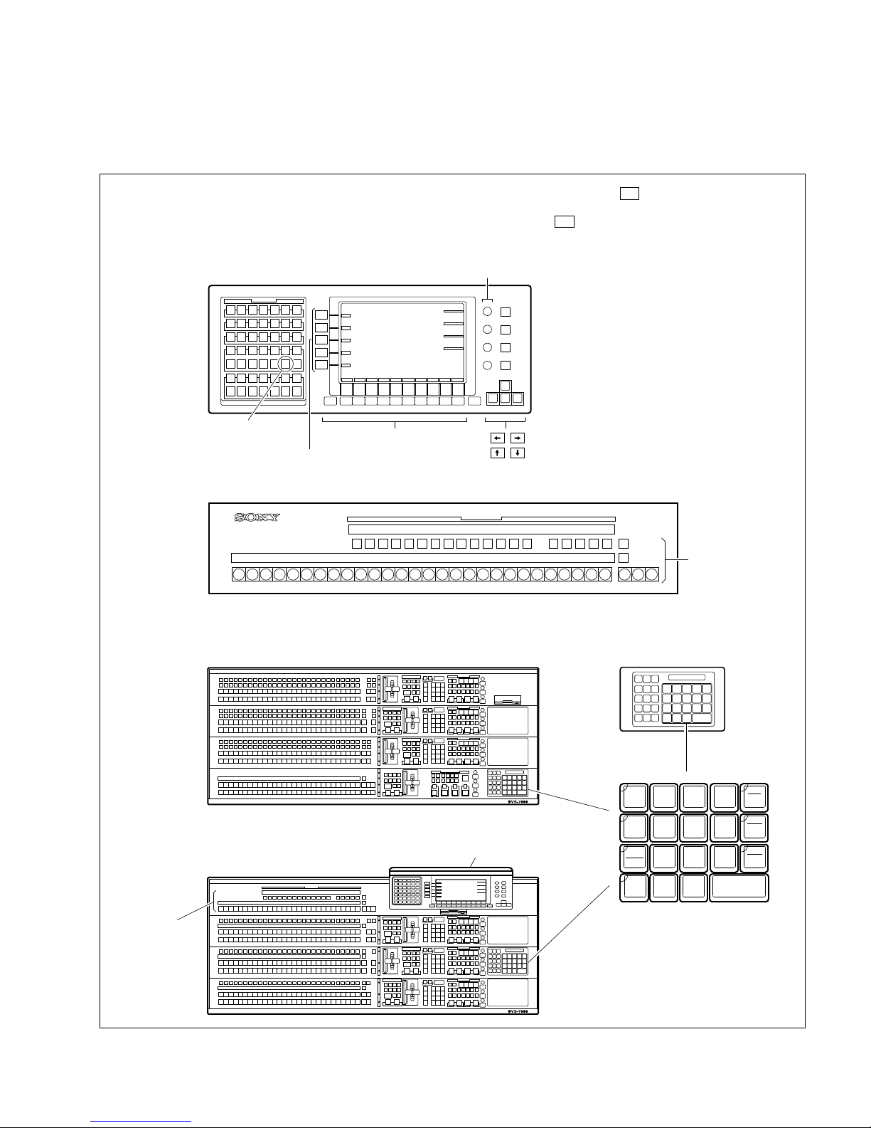
DVS-7000AE IM
6-3
6-1. Operation and Saving of Set-up Data.
<Keys and Display of Control Panel>
The keys and display are named as follows.
. How keys are displayed : ex.) F1 (PANEL)
This means that “PANEL” is indicated above
the Function key F1 on the display.
Display panel
AUX BUS panel
Main panel
. BKDS-702x/702xR/702xLR
. BKDS-701x/701xR/701xLR
Control knobs 1~4
SET UP key
Function keys
AUX BUS buttons
Display panel
Numeric key pad
AUX BUS buttons
keys
keys
Item keys
RCALL
STORE
LEARN
LASTX
TRANS
RATE
456
1
0
23
78 9
+ / –
EFF
DIS
CLR
AUTO
TRANS
TRIM
XPT
DSBL
ENTER
•
Adaptor box
. Only BKDS-70xxR/70xxLR
Page 100

6-4
DVS-7000AE IM
6-2. Installation of Program (BZS-7020A)
6-2. Installation of Program (BZS-7020A)
Before using DVS-7300/7350 system, the operating program of operation software BZS-7020A (option)
is installed to the flash memory in the system.
The program on the flash memory is not cleared by turning the power ON/OFF.
If finishing this process, do not load this process till the version-up of the software is executed.
For the program instaalation, execute “6-2-1. Down Load of Program” , “6-2-2. Initializing of Data on
RAM” and “6-2-3. Initializing of Nonvolatile Memory”.
n
If executing the program installation, the set-up data on the Nonvolatile memory is initialized to the
default status and the data (snap shot and key frame) on the RAM are cleared.
When executing the version-up of the software except for the first program installation, execute the
following processes.
. Before the program installation is executed.
Save the set-up, snap shot and key frame effect into a floppy disk.
. After the program installation is finished.
(1) Load the saved set-up, snap shot and key frame data from the floppy disk.
(2) Save the loaded set-up datum into the nonvolatile memory same as “6-3-4. Saving Set-up Data to
Nonvolatile Memory”.
For details of these processes, refer to user’s guide BZS-7020A.
 Loading...