

SONY BG-2T Service Manual
SERVICE MANUAL
BG2T
CHASSIS
MODEL COMMANDER DEST. CHASSIS NO.
KV-HA14L80 RM-969 ME SCC-U67H-A
MODEL COMMANDER DEST. CHASSIS NO.
3
1
2
6
4
5
9
7
8
JUMP
-
0
SOUND
PROGR
2
MODE
SPACE
SOUND
TV
TRINITRON
®
COLOR TV
KV-HA14L80/HA14P50
RM-969
SECTION 4
CIRCUIT ADJUSTMENTS
4-1. ADJUSTMENT WITH COMMANDER
Service adjustments to this model can be performed using the
supplied Remote Commander RM-969
a. ENTERING SERVICE MODE
With the unit on standby
n
[DISPLAY] n 5 n VOL (+) n [POWER]
This operation sequence puts the unit into service mode.
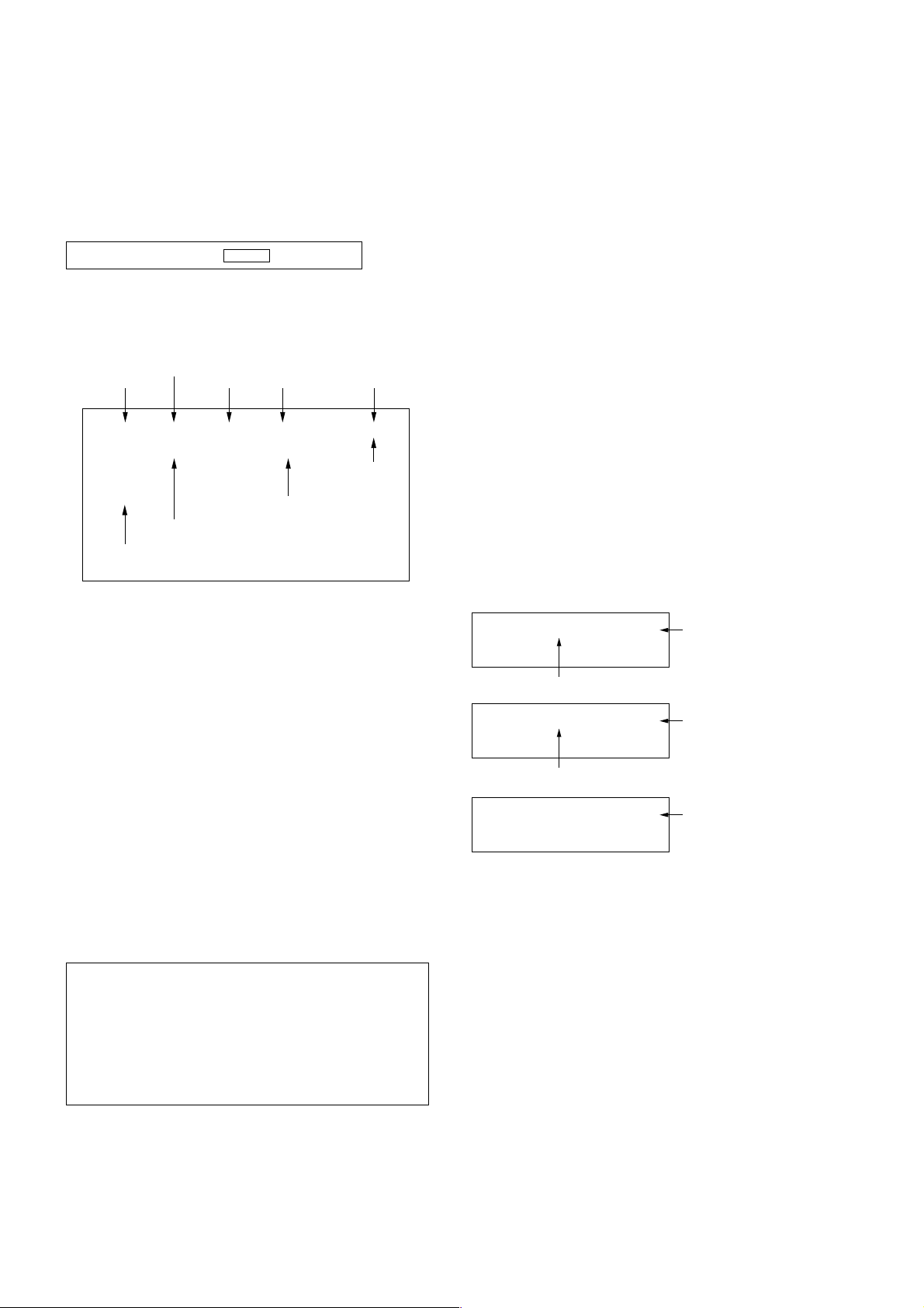
The screen display is :
Item
Adjustment
Mode
Item No
00
080S
(KV-HA14L80)
085S
(KV-HA14P50)
Software version
Suffix No
(OEM Code)
Data
HPS 33 SERVICE
1.6C
00 000A
Total Power-On time (hours)
Depends on signal
50
PAL,SECAM:50
NTSC :60
e. OTHER FUNCTION VIA REMOTE COMMANDER
7, - All the data becomes the values in memory.
8, - All user control goes to the standard state.
5, - Service data initialization (Be sure not to use
usually.)
2, - Copy and write all data.
[MUTE], - Write 50Hz adjustment data to 60Hz or vice
versa.
4-2. ADJUSTMENT METHOD
Item Number 00 HPS
This explanation uses H Shift as an example.
1. Select “00 HPS” with the 1 and 4 buttons.
2. Raise/lower the data with the 3 and 6 buttons.
3. Select the optimum state. (The standard is 1F for PAL
reception.)
4. Write with the [MUTING] button. (The display changes to
WRITE.)
5. Execute the writing with the - button. (The WRITE
display will be changed to red color while excuting, and
back to SERVICE.)
Example on screen display :-
b. METHOD OF CANCELLATION FROM SERVICE
MODE
Set the standby condition (Press [POWER] button on the com-
mander), then press [POWER] button again, hereupon it becomes
TV mode.
c. METHOD OF WRITE INTO MEMORY
1) Set to Service Mode.
2) Press [1] (UP) and [4] (DOWN), to select the adjustment.
4) Press [MUTING] button to indicate WRITE on the screen.
5) Press [0] button to write into memory.
d. MEMORY WRITE CONFIRMATION METHOD
1) After adjustment, pull out the plug from AC outlet, and then
plug into AC outlet again.
2) Turn the power switch ON and set to Service Mode.
3) Call the adjusted items again to confirm adjustments were
made.
1, 4 Select the adjustment item.
↓
3, 6 Raise/lower the data value.
↓
[MUTING] Writes.
↓
- Executes the writing.
00
Adjusted with [3] and [6] buttons.
00
00
Write executed with [0]
33 SERVICE 50HPS
33 WRITE 50HPS
Write with [MUTING]
33 WRITE 50HPS
GREEN
GREEN
RED
The WRITE display
then the display
returns to green
SERVICE
Use the same method for all Items. Use 1 and 4 to select the
adjustment item, use 3 and 6 to adjust, write with [MUTING],
then execute the write with -.
Note :1.In [WRITE], the data for all items are written into
memory together.
2. For adjustment items that have different standard
data between 50Hz or 60Hz, be sure to use the
respective input signal after adjustment.
– 18 –
 Loading...