

AIT Drive
Operating Instructions
4-670-383-13(2)
AIT-1 TAPE DRIVE
AITe90-UL
©2002 Sony Corporation

Safety Regulations
Owner’s Record
The model and serial numbers are located on the bottom. Record the serial
number in the space provided below.
Refer to them whenever you call upon your dealer regarding this product.
Model No. Serial No.
Information
WARNING
To prevent fire or shock hazard, do not expose the
unit to rain or moisture.
To avoid electrical shock, do not open the cabinet.
Refer servicing to qualified personnel only.
MODEL No. for Regulatory Compliance
Your AIT-1 or AIT-2 TAPE DRIVE is assigned the MODEL No. SDX-D420C
or SDX-D520C (respectively) for regulatory compliance certifications. The
number is indicated on the model number label on your drive along with the
rated voltage and current.
2 Safety Regulations
For customers in the USA
You are cautioned that any changes or modifications not expressly approved
in this manual could void your authority to operate this equipment.
FCC Compliance
This equipment has been tested and found to comply with the limits for a
Class B digital device, pursuant to Part 15 of the FCC rules. These limits are
designed to provide reasonable protection against harmful interference in a
residential installation. This equipment generates, uses and can radiate radio
frequency energy and, if not installed and used in accordance with the
instructions, may cause harmful interference to radio communications.
However, there is no guarantee that interference will not occur in a particular
installation. If this equipment does cause harmful interference to radio or
television reception, which can be determined by turning the equipment off
and on, the user is encouraged to try to correct the interference by one or
more of the following measures:
• Reorient or relocate the receiving antenna.
• Increase the separation between the equipment and receiver.
• Connect the equipment into an outlet on a circuit different from that to
which the receiver is connected.
• Consult the dealer or an experienced radio/TV technician for help.
The shielded interface cable recommended in this manual must be used with
this equipment in order to comply with the limits for a digital device pursuant
to Subpart B of Part 15 of FCC Rules.
CAUTION
The main plug on this equipment must be used to disconnect main power.
Please ensure that the socket outlet is installed near the equipment and shall be
easily accessible
.
ACHTUNG
Zur Trennung vom Netz ist der Netzseker aus der Steckdose zu ziehen,
welche sich in der Nähe des Gerätes befinden muß und leicht zugänglich
sein soll.
HINWEIS
Der höchste Schalldruckpegel beträgt 70 dB (A) oder weniger gemäß ISO
7779.
NOTICE
Use the power cord set approved by the appropriate testing organization for
the specific countries where this unit is to be used.
HINWEIS
Die 3-adrige Geräteanschlußleitung muß Typ H05VV-F oder H05VVH2-F
sein und nach DIN VDE 0625 geprüft sein. Der Stecker und die
Gerätesteckdose müssen nach DIN VDE 0620 bzw DIN VDE 0625 geprüft
sein. Der Leitungsquerschnitt kann 0,5 mm2 betragen wenn die
Anschlußleitung eine Länge von 2 m nicht überschreitet. Anderenfalls muß
der Leitungsquerschnitt mindestens 0,75 mm2 betragen.
If you have any questions about this product, please refer to Sony contact in
the instruction manual.
English
DECLARATION OF CONFORMITY
Trade Name: SONY
Model: SDX-D420C or SDX-D520C
Responsible Party: Sony Electronics Inc.
Address: 680 Kinderkamack Road, Oradell NJ 07649 USA
Telephone number: 201-930-6972
This device complies with part 15 of the FCC Rules. Operation is subject to
the following two conditions:
(1) This device may not cause harmful interference.
(2) This device must accept any interference received, including
interference that may cause undesired operation.
Diese Ausrüstung erfüllt die Europäischen EMC-Bestimmungen für die
Verwendung in folgender/folgenden Umgebung(en):
– Wohngegenden
– Gewerbegebiete
– Leichtindustriegebiete
(Diese Ausrüstung erfüllt die Bestimmungen der Norm EN 55022,
Klasse B.)
Safety Regulations 3

Table of Contents
How to Use this Guide ...................................................................... 5
Chapter 1
Introduction
Chapter 2
Preparation
Chapter 3
Operation
Chapter 4
Care and
Maintenance
About the AIT Drive........................................................................... 6
Features....................................................................................................6
System Requirements .............................................................................. 7
Useable Cartridges...................................................................................7
Part Names and Functions............................................................... 8
Front Panel...............................................................................................8
Drive Status .............................................................................................9
Rear Panel.............................................................................................. 10
Supplied Items................................................................................. 11
Interconnections ............................................................................. 12
i.LINK ................................................................................................... 13
Using the AIT Drive ..............................................................................15
Removing the Cartridge ........................................................................ 16
Taking Care of the Drive................................................................. 17
Safety Considerations ............................................................................17
Avoiding Damage.................................................................................. 17
Taking Care of Cartridges .............................................................. 19
Usage Precautions ................................................................................. 19
Storage Precautions ...............................................................................19
Head Cleaning ................................................................................. 20
Cleaning................................................................................................. 20
Appendix
• Sony cannot accept liability for data written to cartridges lost as a result of using this product.
• Sony bears no responsibility for any financial damages, lost profits, or claims made by third parties
arising from the use of this product.
Specifications.................................................................................. 21
Sony Contacts ................................................................................. 22
4 Table of Contents

How to Use this Guide
This guide describes how to use and care for the AITe90-UL AIT drive.
Please read it carefully before using the drive and save it for future reference.
The guide consists of four chapters and an appendix. Refer to the chapters
that relate to your use of the drive.
Chapter 1 Introduction
Describes the features of the drive, system requirements, and the names and
functions of each part.
Chapter 2 Preparation
Describes the necessary connections between the drive and the host
computer. Read this chapter when you install the drive.
Chapter 3 Operation
Describes how to use the drive, including how to turn it on, and how to insert
and remove cartridges. Read this chapter when you are going to use the drive.
Chapter 4 Care and Maintenance
Describes how to take care of the drive and cartridges, and how to clean the
drive heads. Read this chapter before using the drive.
Appendix
Contains the specifications of the drive.
Notation
IEEE 1394 and i.LINK refer to the same type of interface. In this guide, we
have used i.LINK throughout to refer to the interface.
Trademarks
• Microsoft and Windows are either registered trademarks or trademarks of
Microsoft Corporation in the United States and/or other countries.
• i.LINK™ is a designation referring to IEEE 1394-1995 and IEEE 1394a-
2000. i.LINK and the i.LINK logo “ ” are trademarks of Sony
Corporation.
• All other system names, products, and services are either registered
trademarks or trademarks of their respective owners. The ™ or ® marks do
not appear in this manual.
How to Use this Guide 5

Chapter 1 Introduction
About the AIT Drive
The AITe90-UL is an external AIT drive using data cartridges that conform
to the AIT-1 format.
Features
The AITe90-UL AIT drive has the following features.
• Uses the Advanced Intelligent Tape (AIT) format AIT-1 data cartridges.
AIT-1 data cartridges provide 35 GB of storage (no compression) on a
230-m tape. The Read After Write function and Third Level Error
Correction Code ensure high data reliability.
• The drive comes with a data compression function, providing a maximum
of 91 GB of storage on an AIT-1 data cartridge (230-m tape).
• Stored data is automatically checked for compression. The drive can also
read data recorded with other devices.
• The drive is equipped with a USB and i.LINK (IEEE 1394) interface. You
can therefore connect the drive to either connector to your computer.
*1
Note
You cannot use the USB and i.LINK interfaces simultaneously.
• The drive supports Hot Plug, which means that you can connect and
disconnect it while the drive and/or your computer is on.
*1
Assuming a 2.6:1 hardware compression ratio.
The actual degree of compression during recording depends on the system environment and
the type of data.
6 Chapter 1 Introduction
System Requirements
The following are the minimum system requirements to use the drive.
• PC/AT-compatible computer (300 MHz or faster)
• Running Windows XP, Windows 2000, Windows Me, or Windows 98
Second Edition
• CD-ROM drive (to install the software necessary to the drive)
• i.LINK and/or USB interface
Useable Cartridges
The AITe90-UL can be used with data cartridges marked with the AIT-1 logo.
AIT-1 Data Cartridges
Name Capacity (no compression)
SDX1-35C 35 GB
SDX1-25C 25 GB
AIT-1 Logo
AIT Cleaning Cartridges
Name Description
SDX1-CL AIT drive cleaning cartridge
Note
Be sure to use only data cartridges designed specifically for AIT (do not use
8 mm video cartridges) as this may damage the drive.
Chapter 1 Introduction 7
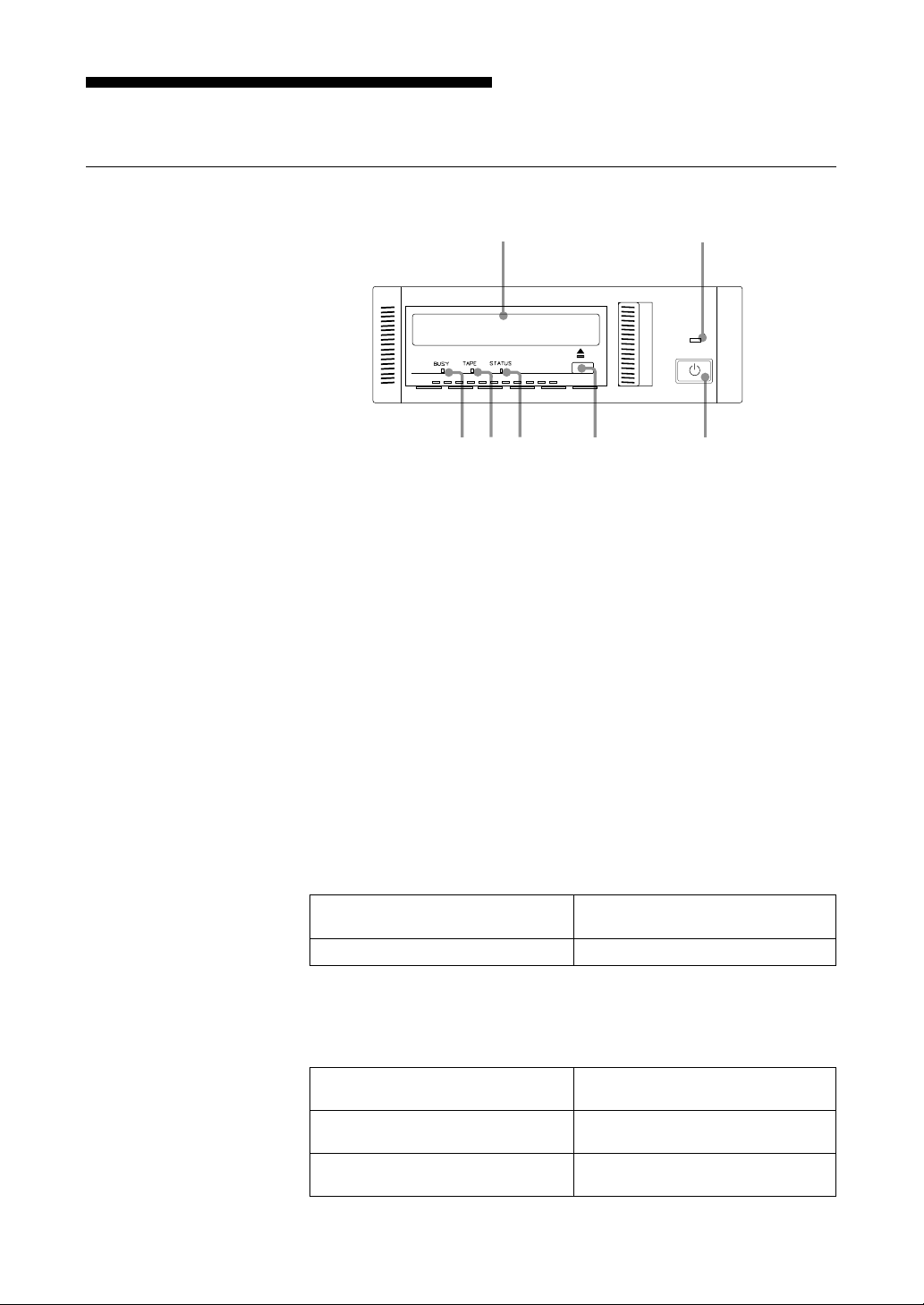
Part Names and Functions
1
2
Front Panel
345 6 7
1 AIT Data Cartridge Receptacle
See page 15 for information on inserting and removing a AIT data
cartridge.
POWER
Figure 1-2. Front panel
2 POWER Indicator
Lights while the drive is on.
3 BUSY Indicator
Lights when data is transferred through the USB or i.LINK interface. It
also lights in the following situations:
• When reading data from or writing data to a data cartridge
• When inserting or ejecting a data cartridge
4 TAPE Indicator
When a AIT cartridge is inserted, the indicator lights. It also lights in the
following situations:
Inserting and removing a cartridge repeated blinking (same on-off
interval).
Cartridge deteriorated alternating long-short blinking.
5 STATUS Indicator
Lights when the data cartridge in the drive is write-protected. It also in
the following situations:
Drive needs cleaning repeated long on, short off blinking.
End of tape during cleaning
Drive malfunction repeated short on (once or twice),
repeated blinking (same on-off
interval).
long off blinking.
8 Chapter 1 Introduction
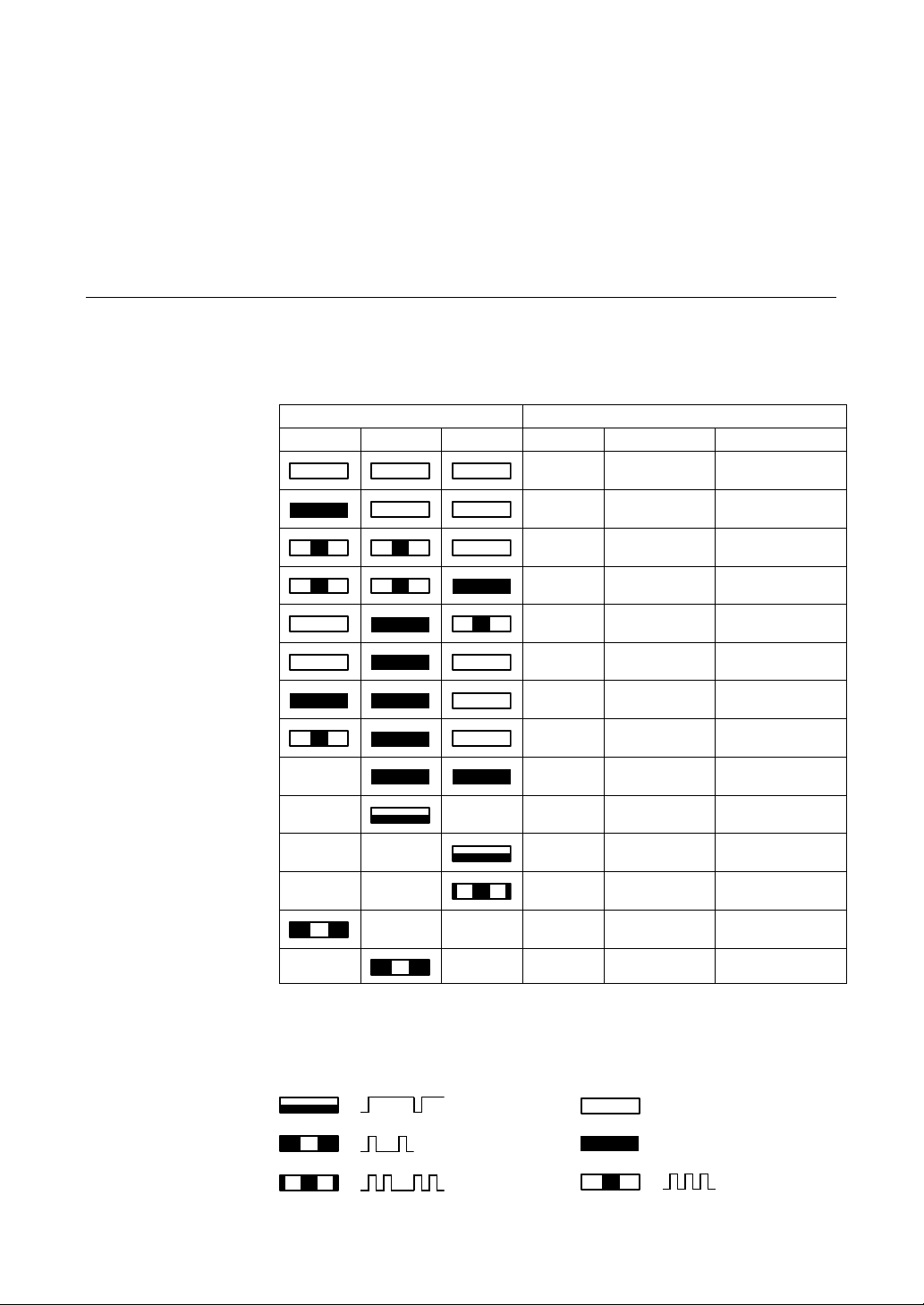
Drive Status
6 EJECT Button
Push to remove a data cartridge from the drive.
7 POWER Switch
Press to turn the drive on or off.
The status of the AITe90-UL can be interpreted by reading the indicators as
follows.
LED State
BUSY TAPE STATUS Activity Cartridge Other
None None None
✽1 None None
Drive
Drive
None Inserted
None Inserted None
✽1 Inserted None
Reading/Writing
Independent
Independent Independent
✽2
—
✽2
—
✽2
—
✽1
Data transfer through the USB or i.LINK interface
✽2
Not defined
✽3
Change cartridges
✽4
Reset drive
✽5
Eject cartridge
✽2
—
✽2
—
✽2
—
✽2
—
✽2
—
—
—
—
—
—
—
Inserting/Removing
Inserting/Removing
✽2
✽2
✽2
✽2
✽2
✽2
None
Write-protected
Cleaning tape depleted
Inserted None
Inserted Write-protected
Inserted Error rate warning
✽2
—
✽2
—
✽2
—
✽2
—
Cleaning request
Self-test failure
Operational error
Operational error
✽3
✽4
✽4
✽5
1 pulse (3.5 sec on / 0.5 sec off)
1 pulse (0.25 sec on)
2 pulses (0.25 sec on/0.5 sec off)
off
on
1 pulse (0.25 sec on / 0.25 sec off)
Chapter 1 Introduction 9

Rear Panel
1
23
Figure 1-4. Rear Panel
4
1 AC IN Connector
Connect the supplied power cable here.
2 i.LINK Connectors ( )
Connects to the i.LINK connector of the host computer.
3 USB Connector ( )
Connects to the USB connector of the host computer or a USB hub.
4 Cooling Fan
10 Chapter 1 Introduction

Chapter 2 Preparation
After you confirm that all the necessary items are accounted for, connect the
drive to the host computer or to a USB hub.
Supplied Items
When you open the package, make sure that it contains the following. Contact
your supplier if any of these items are missing and/or damaged.
• AIT-1 drive
• Quick start guide
• AIT-1 data cartridge (SDX1-35C)
• Operating instructions CD-ROM
• 1Safe™ CD-ROM
• USB 2.0 cable
• i.LINK cables (6-pin to 6-pin, 6-pin to 4-pin, 1 each)
• Power cable
• Warranty card*
• Safety regulations (2)
*Warranty coverage may vary from region to region.
Chapter 2 Preparation 11

Interconnections
Connecting to the USB Interface
Connect the USB connector of the host computer or USB hub to the USB
connector of the drive with the USB cable.
Connecting to the i.LINK Interface
Connect the i.LINK connector of the host computer to the i.LINK connector
of the drive with the one of the i.LINK cables. You can also add the drive to a
daisy chain.
Caution
You cannot use the USB and i.LINK interfaces simultaneously.
12 Chapter 2 Preparation
AC power
USB or i.LINK cable (supplied with the drive)
Daisy Chain Example
AITe90-UL
Host computer
Interface

i.LINK
What is i.LINK?
This section explains the specifications and features of i.LINK.
Restrictions that are not outlined below may apply, depending on the features
and specifications of individual i.LINK devices.
i.LINK is a digital serial interface that allows bi-directional transfer of digital
video and audio data between devices equipped with i.LINK connectors. It
also allows one device equipped with an i.LINK connector to control another
device that is similarly equipped.
Two i.LINK devices are connected through a single i.LINK cable. Using
i.LINK, a wide variety of audio-visual devices can be connected for control
or data transfer. Use of i.LINK is expected to expand to a wider variety of
devices in the future, providing even more options for control and data
transfer.
When multiple i.LINK devices are connected in series, control and data
transfer can be extended to devices connected through other i.LINK devices,
as well as to those connected directly. This means that devices can be
connected in any sequence. However, whether data can be transferred with a
particular device, as well as how or if that device can be controlled, depends
on the characteristics and specifications of the individual device.
Note
i.LINK, the internationally popular name for the IEEE 1394 interface
standard, is a Sony trademark.
IEEE 1394 is an international standard established by the Institute of
Electrical and Electronics Engineers.
Connection Using i.LINK
i.LINK devices are connected in series using i.LINK cables. This is often
referred to as a “daisy chain”.
i.LINK cable
Data transfer and control are possible even when two i.LINK devices
are connected through other devices.
Chapter 2 Preparation 13

Branching is also possible
• When devices have three or more i.LINK connectors, it is possible to create
branches midway through the i.LINK daisy chain.
• Up to 63 i.LINK devices (including this drive) can be interconnected.
However, only 17 devices can be present on the longest individual path. (Up
to 16 i.LINK cables can be used in the chain making up a path of the
maximum possible length.)
The length of a path is indicated in terms of the number of i.LINK cables used,
with each cable counted as one “hop.” For example, in the figure below, the path
between A and C is 6 hops, while that between A and D is 3 hops.
Any of the paths (A p B, A p C, A p D, B p C, B p D, and C p D) can be
composed of a maximum of 17 devices. (A maximum of 16 hops.)
Care must be taken to ensure that no path loops back up on itself
The digital signal passes through all the connected i.LINK cables. Circular
connections must be avoided to prevent signals from returning to the device
from which they originated. Such circular connections are referred to as
“loops.”
Examples of correct connections
Examples of loops
Connection Precautions
• Some i.LINK devices, such as computers, must be turned on to relay data to
other i.LINK devices. When connecting an i.LINK device, refer to the
instructions accompanying the device.
• The maximum data transfer rate supported by any given i.LINK device is
indicated near the i.LINK connector. The maximum i.LINK data transfer
rates are defined as being approximately 100, 200, and 400 Mbps,
respectively noted as S100, S200, and S400. When devices having different
maximum data transfer rates are connected together, rates achieved by
individual devices may be less than their rated maximums.
14 Chapter 2 Preparation

Chapter 3 Operation
This chapter describes how to use the AIT drive, and how to handle data
cartridges.
Using the AIT Drive
1 Press the POWER switch on the front panel.
The POWER indicator lights, and the STATUS, BUSY, and TAPE
indicators blink as the self-test is performed.
2 When the three indicators stop blinking and the BUSY indicator lights,
insert a data cartridge as indicated below. As the tape is being loaded, the
TAPE indicator blinks. If the tape is loaded successfully, the TAPE
indicator lights. (If the cartridge is write-protected, the STATUS
indicator also lights.)
Figure 3-1. Inserting a data cartridge
3 Computer software controls tape reading and writing. While reading or
writing, the BUSY indicator blinks.
Note
Do not disconnect the USB or i.LINK cable when you are reading or
writing data as this could cause malfunctions.
Chapter 3 Operation 15

Removing the Cartridge
Press the EJECT button.
A few seconds later, the ejection procedure starts (rewinding the tape, etc.),
and the BUSY and TAPE indicators blink simultaneously. When the ejection
procedure ends, the cartridge is ejected automatically.
Notes
• Do not press the EJECT button while the BUSY indicator is blinking (data
is being written or read) as this may destroy data on the tape.
• The ejection procedure may take up to a few minutes to complete. For this
reason, it is important not to turn off the drive before the cartridge is
ejected.
Figure 3-2. Press the EJECT button
16 Chapter 3 Operation

Chapter 4 Care and Maintenance
Taking Care of the Drive
Safety Considerations
■ Power
• 100 to 240 V AC.
• Avoid plugging into the same outlet as high-current equipment like copiers
or shredders.
■ Power Cable Precautions
• Do not crush the cable or place heavy items on it. If the cable insulation
appears worn or broken, do not use the cable.
• Always unplug the cable by holding the plug: never pull the cable itself, as
it will break.
• If the drive is not being used for a long time, unplug the cable from the
outlet.
Avoiding Damage
■ Avoid shock and vibration
Intense shock, such as from dropping the drive, will damage it.
■ Environmental considerations
Do not store or use the drive in locations subject to:
• high humidity • excessive dust
• high temperature • intense vibration
• direct sunlight • sudden changes in temperature
■ Proper ventilation
To avoid overheating, install the drive where it has free air circulation around
the case and cooling fan. Also, do not cover the drive during operation. The
drive can malfunction if its internal temperature rises too high.
■ Avoid sudden changes in temperature
If the drive is moved from a cool place to a warm place, or if the room
temperature suddenly rises, moisture may condense inside the case. After a
sudden change in temperature, wait at least one hour before turning the drive
on.
Chapter 4 Care and Maintenance 17

■ Abnormal occurrences
If the drive behaves abnormally, or if it begins to smell or smoke,
immediately unplug it from the wall outlet and contact your supplier for
assistance.
■ Cabinet cleaning
Wipe the cabinet with a soft dry cloth. For heavy dirt, wipe with a soft cloth
moistened with a gentle liquid soap, then wipe again with a soft dry cloth. Do
not use alcohol, paint thinner, bug sprays or other volatile solvents, as they
can damage the finish.
18 Chapter 4 Care and Maintenance
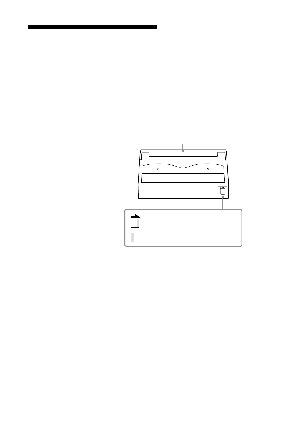
Taking Care of Cartridges
Usage Precautions
• Avoid dropping the cartridges and high vibrations.
• The shutter on the face of the cartridge opens automatically when it is
inserted into the drive. Do not open the shutter by hand, as touching the tape
may damage it.
• The cartridge is precisely aligned. Do not try to open or dismantle it.
• The write-protect switch on the face of the cartridge is used to prevent the
tape from being written to or accidentally erased. If you do not need to write
to the tape, move this switch to the write-protect position.
Lid
• In case of a sudden change in temperature, condensation may interfere with
• Avoid unnecessary insertion and removal of cartridges if you do not need to
• When you are done using the drive, remove the cartridge.
• Avoid touching the AIT cartridge’s Memory in Cassette (MIC) terminals as
Storage Precautions
• Keep cartridges in their cases when not in the drive.
• Avoid storing cartridges in dusty locations, in direct sunlight, near heaters
• Do not place cartridges on dashboards or in car storage trays.
Using your fingernail, push the switch in the
direction of the arrow to protect the tape
from writing or accidental erasure.
Return the switch to its original position to
re-enable writing.
Figure 4-1. Write-protect switch
reading and writing to a tape.
write or read a tape.
they are sensitive precision components.
or air conditioners, or in humid locations.
Chapter 4 Care and Maintenance 19

Head Cleaning
To keep the AIT drive in top condition, clean the head as needed using the
proper head cleaning cartridge. When the head needs cleaning, the STATUS
indicator blinks (see page 9).
Cleaning
1 Insert the head cleaning cartridge into the AIT drive. Cleaning starts
2 About 15 seconds later, cleaning stops and the cartridge is ejected
automatically.
automatically.
One head cleaning cartridge can be used about 50 times.
Note
Do not rewind the cleaning cartridge and reuse it. When you reach the
end of the cartridge, dispose of it and buy a new one.
20 Chapter 4 Care and Maintenance

Appendix
Specifications
■ Performance
Storage Capacity 35 GB uncompressed
Data Transfer Rate 4 MB/s uncompressed
Burst Data Transfer Rate 480 Mbps maximum (USB)
Bit Error Rate less than 10
Initialization Time less than 5 seconds
Load Time less than 24 seconds
Unload Time less than 30 seconds
Rewind Time less than 105 seconds
(with 230 m AIT-1 data cartridge)
91 GB compressed
(with 230 m AIT-1 data cartridge*1)
(TAPE) 10.4 MB/s compressed
400 Mbps maximum (i.LINK)
-17
(with 230 m AIT-1 data cartridge)
*1
■ Operating Environment
Operating Temperature: 10 to 35 °C
Non-operating Temperature: –40 to +70 °C
■ Power Supply & Miscellaneous
Rated Power Supply 100 to 240 V AC, 50/60 Hz, 1.2 A
Case Dimensions 198 × 64.5 × 246 mm (W × H × D)
Mass 2.4 kg
Equipment Quick start guide 1
Humidity: 30 to 80%
(no condensation)
Maximum wet bulb temperature: 26 °C
Humidity: 10 to 90%
(excluding projections)
AIT-1 data cartridge (SDX1-35C) 1
Operating instructions CD-ROM 1
1Safe™ CD-ROM 1
USB 2.0 cable 1
i.LINK cables
(6-pin to 6-pin, 6-pin to 4-pin, 1 each) 2
Power cable 1
Warranty card 1
Safety regulations 2
Specifications may be subject to change, in the interest of technological
improvement, without notice or obligation.
*1
Assuming a 2.6:1 hardware compression ratio.
The actual degree of data compression during recording depends on the system environment
and type of data.
Appendix 21

Sony Contacts
For further information, please contact:
Sony Electronics Inc., Tape Storage Solutions (USA)
URL: http://www.storagebysony.com/
Sony Corporation
Electronic Devices Marketing Group, Product Marketing Div.
Computer Peripherals Dept. Tape Streamer Section
Osaki Gate City East Tower, 1-11-1, Osaki
Shinagawa-ku, Tokyo, 141-0032 Japan
TEL: (81) 3-5435-3486 FAX: (81) 3-5435-3565
Sony of Canada Ltd., AV/IT Marketing Group
Computer Peripherals Product Marketing
115 Gordon Baker Road Toronto, Ontario, M2H 3R6 Canada
TEL: (416) 499-1414 or (1) 800-961-7669
FAX: (416) 499-8541
Sony Computer Peripherals & Compornents Europe
URL: http://www.sonyisstorage.com/
Electronics Devices Marketing (Singapore)
(A division company of Sony Electronics (S) Pte. Ltd.)
Enterprise Storage Solutions Dept.
2 International Business Park, #01-10 Tower One,
The Strategy, Singapore 609930
TEL: 65-6544-8000 FAX: 65-6544-7390
Sony Corporation of Hong Kong Ltd.
Computer Peripheral Sales & Marketing Division
Electronic Devices Marketing Hong Kong
The Lee Gardens 45 F., 33 Hysan Avenue, Causeway Bay, Hong Kong
TEL: (852) 2909-1008 FAX: (852) 2909-2001
Sony Corporation of Hong Kong Ltd. Beijing Rep. Office
Computer Peripheral Div.
Full Link Plaza Tower A 11 F., No.18 Chaoyangmenwai Ave., Beijing
100020 P.R.C.
TEL: 86-10-6588-0558 FAX: 86-10-6588-0855
URL: http://www.sony.com.cn
Sony Corporation of Hong Kong Ltd. Shanghai Rep. Office
HSBC Tower 44 F., 101 Yin Cheng East Road, Pudong, New Area,
Shanghai, P.R.C. Postcode 200120
TEL: 86-21-6841-3222 FAX: 86-21-6841-0280
22 Appendix

Sony Brasil Ltda.
Rua Inocencio Tobias, 125-BlocoA, CEP01144-000, São Paulo -SP-Brasil
TEL: (55) 11-3824-6586 to 6598 FAX: (55) 11-3611-9064
URL: http://www.sonybrasil.com
Sony Australia Ltd., Information Technology Products Division
P.O. Box 377, NSW 1670, Australia
TEL: (1) 800-226-429 FAX: (61) 2-9870-8564 A.C.N. 001 215 354
URL: http://www.sony.com.au/home.asp
E-mail: informatica@ssp.br.sony.com
Sony Chile Ltda
Av. Kennedy 8017, Las Condes, Santiago, Chile
TEL: (02) 210-6000 FAX: (02) 210-5417
Sony Taiwan Limited
Optical Devices Storage Dept. Data Storage Section
5F, 145 Changchun Road, Taipei 104, Taiwan
TEL: 886-2-2522-7920 FAX: 886-2-2522-2153
Sony Korea Corporation EDMK CP Sales & Marketing Team
ASEM Tower 34 F., World Trade Center, 159-1, Samsung-Dong, KangnamKu, Seoul, 135-798, Korea
TEL: 82-2-6001-4249 FAX: 82-2-6001-4115
URL: http://www.sony.co.kr/cp/
Sony Gulf FZE Computer Display & Peripheral Div.
P.O.Box 16871, Jebel Ali, Dubai, U.A.E.
TEL: 971-4-8815488 or 8816912 FAX: 971-4-8817210 or 8816259
Sony Marketing of Japan
Business Solution Dept. Server Solution Marketing Section
URL: http://www.sony.co.jp/STORAGE
Appendix 23

 Loading...