

Page 1
4-681-229-02(1)
Rack Mounting Kit
取扱説明書 Page 2 ______________________________________
Operating Instructions Page 7 _____________________________
お買い上げいただきありがとうございます。
電気製品は安全のための注意事項を守らないと、
火災や人身事故になることがあります。
この取扱説明書には、事故を防ぐための重要な注意事項と製品の取り扱いかたを示してあり
ます。この取扱説明書をよくお読みのうえ、製品を安全にお使いください。お読みになった
あとは、いつでも見られるところに必ず保管してください。
JP
GB
ACY-RKSE
© 2003 Sony Corporation
Page 2

目次
©
はじめに ........................................................................................3
必要な工具 ............................................................ 3
設置上のご注意 ..................................................... 3
同梱品を確認する ....................................................................... 3
準備をする ....................................................................................4
インナーレールを取り出す ................................... 4
ベースプレートの準備をする ............................... 4
ラックの準備をする ............................................. 5
ベースプレートをラックに取り付ける ................. 6
S-AIT テープドライブユニットをラックに設置する ......6
2003 Sony Corporation. All rights reserved
商標について
・ Sony、Advanced Intelligent Tape、Super Advanced Intelligent Tape は日本およびその他の国におけるソニー株式
会社の登録商標または商標です。
・ その他、本書に記載されている製品名は各社の登録商標または商標です。
2
Page 3
はじめに
同梱品を確認する
本ラックマウントキットを使うと、EIA STANDARD の
19 インチラックに S-AIT テープドライブユニットを 2
台設置できます。
ご注意
本書に記載されているネジ以外のネジを外さないでく
ださい。落下してけがの原因または機器の損傷につな
がる可能性があります。
S-AIT テープドライブユニットの質量は約 7kg です。
必ず 2 人以上で作業してください。腰を痛めたり、落
下してけがの原因または機器の損傷につながる可能性
があります。
必ず S-AIT テープドライブユニットの電源を切り、
ケーブル類をすべて取り外してから、作業を行ってく
ださい。
必要な工具
ラックマウントキットの取り付けには、次の工具が必要
です。
・ プラスドライバー
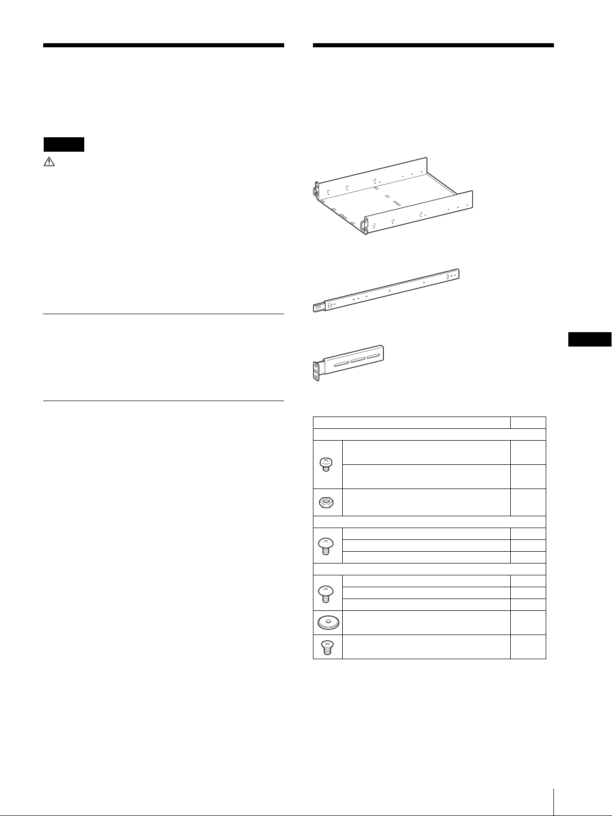
パッケージを開けたら、以下のものがそろっているかお
確かめください。付属品の中に欠けているものがあると
きは、お買い上げ店にご連絡ください。
ベースプレート(1)
レール(2)
ブラケット(4)
JP
設置上のご注意
S-AIT テープドライブユニットをラックに取り付ける前
に、以下の点に注意してください。
・ S-AIT テープドライブユニットの動作時に、温度 5 ~
35 ℃、湿度 20 ~ 80%を保てる場所に設置してくだ
さい。室内温度 15 ~ 25 ℃の範囲を保てる場所に設置
することをおすすめします。
・ S-AIT テープドライブユニット背面のファンや通気孔付
近に、ケーブルやその他の障害物がこないように設置し
てください。
・ S-AIT テープドライブユニットをラックに取り付けたと
きに、ラックの重量バランスが崩れて転倒することを防
ぐため、ラックに転倒防止金具などを取り付けることを
おすすめします。
・ ラック内のすべての機器に電源供給回路が適合すること
を確認してください。
・ 使用するコンセントや電源ケーブルが正しくアースされ
ていることを確認してください。
・ ラックマウントキットを設置しているときに、静電気が
放電しないように作業環境を整えてください。作業中
は、静電防止マットやアースされた静電防止リストバン
ドを使用してください。
ネジ類
種類 個数
レール用取り付けネジ+ナット
インナーレール用ネジ M4 × 5 十字穴付トラ
ス小ネジ
アウターレール用ネジ M4 × 8 十字穴付トラ
ス小ネジ
アウターレール用ナット M4 皿型座金ナット 4
ブラケット用取り付けネジ
M5 × 10 、十字穴付バインド小ネジ 8
10-32 UNF × 3/8、十字穴付ナベ小ネジ 8
12-24 UNC × 3/8 、十字穴付ナベ小ネジ 8
ベースプレート用取り付けネジ
M5 × 10 、十字穴付バインド小ネジ 2
10-32 UNF × 3/8 、十字穴付ナベ小ネジ 2
12-24 UNC × 3/8 、十字穴付ナベ小ネジ 2
固定用足 8
M3 × 5 、十字穴付皿小ネジ 8
・ 取扱説明書(本書)(1)
8
4
はじめに / 同梱品を確認する
3
Page 4
準備をする
レールと金具類をベースプレートとラックに取り付けて
準備をします。
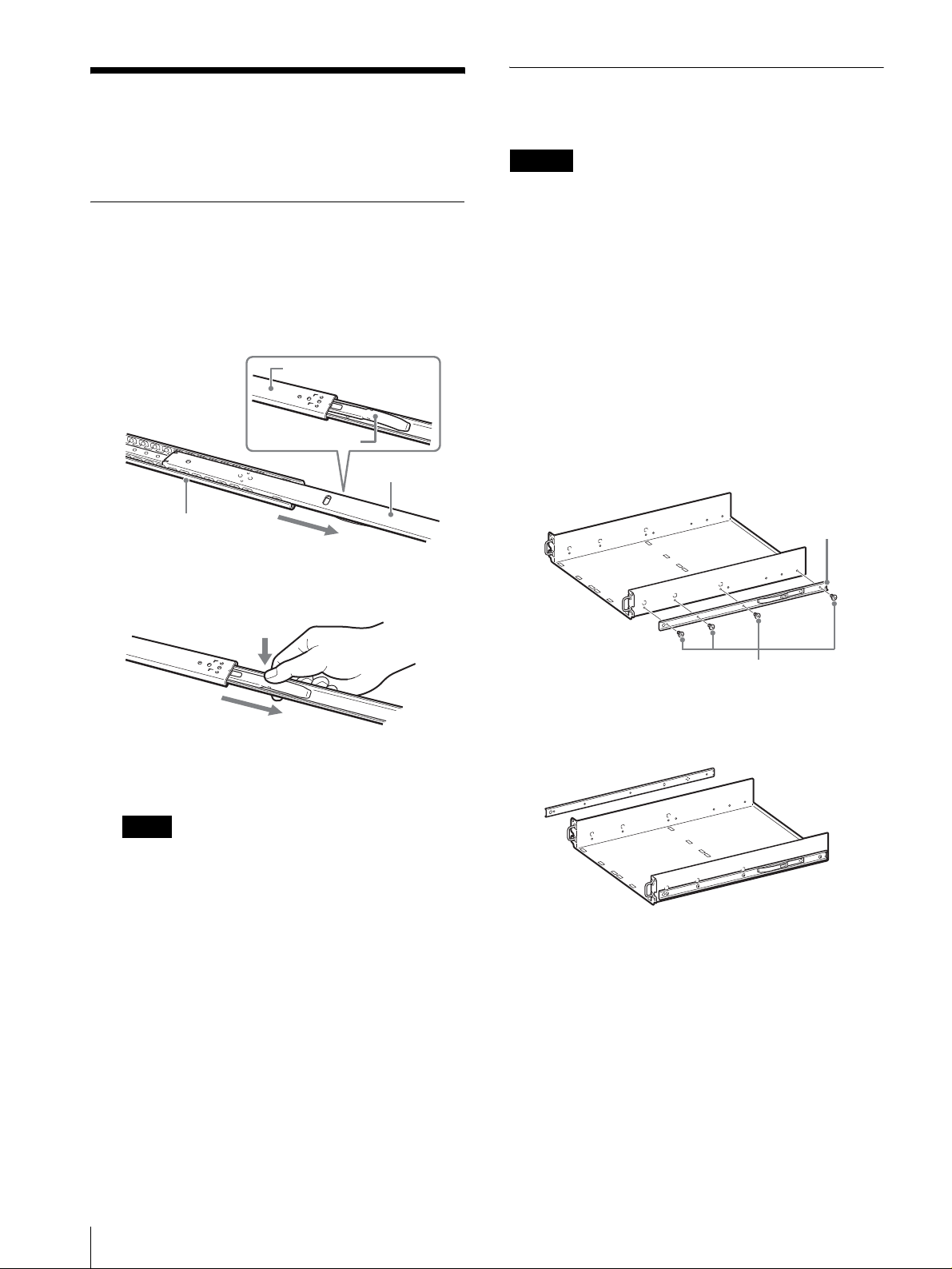
インナーレールを取り出す
アウターレールからインナーレールを取り出します。
1
アウターレールからインナーレールを、止まる位置
まで引き出す。
板バネが出てくると止まります。
アウターレールの裏側
板バネ
インナーレール
ベースプレートの準備をする
インナーレールをベースプレートに取り付けます。
ご注意
・ 体にたまった静電気により部品を破損する場合がありま
す。作業を始める前に、必ずベースプレート本体の金属
部分(塗装されていない部分)に触れてください。
・ 作業のために指定されている部品以外は内部部品に触ら
ないでください。破損した場合は、有償修理となりま
す。
インナーレールを取り付ける
1
インナーレール用ネジとナットを使って、インナー
レールを取り付ける。
インナーレールの取り付け方向(前後)を確認し、
インナーレールの大きい丸穴を前側にして、4 本の
ネジで固定してください。
アウターレール
2
アウターレールを裏返し、板バネを押してロックを
解除しながら、インナーレールを引き抜く。
3
同様にして、もう 1 本のアウターレールからインナー
レールを取り出す。
メモ
インナーレールはベースプレートに、アウターレー
ルはラックに取り付けます。
インナーレール
インナーレール用ネジ
2
同様にして、もう一方の側面にインナーレールを取
り付ける。
4
準備をする
Page 5
ラックの準備をする
アウターレールをブラケットに取り付ける
ブラケットとアウターレールをラックに取り付けます。
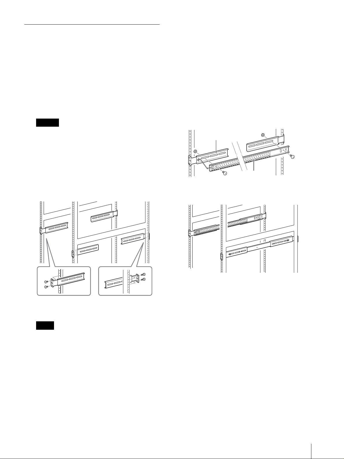
ブラケットを取り付ける
アウターレールを固定するためのブラケットをラックに
取り付けます。
1
ブラケットを取り付ける位置を決める。
各ブラケットを取り付ける位置に、フェルトペンな
どで印を付けておくことをおすすめします。
ご注意
4 個のブラケットの高さを合わせないでベースプレー
トを取り付けると、誤動作の原因となりますのでご注
意ください。
2
ブラケット用取り付けネジを使って、ラックの前側
と後ろ側にブラケットを取り付ける。
ブラケット用取り付けネジは、3 種類のネジから
ラックのネジ穴に合うものを選び、各 2 本のネジで
固定してください。
1
アウターレールをブラケットにのせて、ブラケット
のネジ穴とアウターレールのネジ穴を合わせ、アウ
ターレール用ネジとナットを使って止める。
・ アウターレールの取り付け方向(前後)を確認し、
アウターレールの四角い突起を前側にして、前後
2 箇所をネジとナットで固定してください。
・ 前側のブラケットにアウターレールを取り付ける
ときは、アウターレールの前側がブラケットの段
になった部分に当たるまでスライドさせてくださ
い。
ブラケット
アウターレール
2
同様にして、もう一方の側面にアウターレールを左
右対称の位置に取り付ける。
固定するときは、ブラケットの長穴の中心にラック
のネジ穴を合わせてください。
メモ
・ ブラケットの向きと高さをまちがえないように気
をつけてください。
・ ブラケットがお使いのラックに合わない場合は、
ラックメーカーにお問い合わせください。
準備をする
5
Page 6

ベースプレートをラックに取り付ける
ベースプレートをラックに取り付けます。
1
ベースプレートを持ち上げ、インナーレールをアウ
ターレールにのせて奥までスライドさせる。
S-AIT テープドライブユ
ニットをラックに設置す
る
板バネ
途中でスライドが止まるときは、板バネを押しなが
ら再度スライドさせると、奥まで挿入できます。
メモ
・ アウターレールにインナーレールをうまくはめ込
めない場合は、ブラケットの高さが合っていない
可能性があります。再度ブラケットの位置を調整
してください。
・ ベースプレートがお使いのラックに合わない場合
は、ラックメーカーにお問い合わせください。
ベースプレート
インナーレール
アウターレール
ベースプレートには、S-AIT テープドライブユニットを 2
台設置できます。
1
ベースプレートの下にスペースがない場合は、S-AIT
テープドライブユニット底面のゴム足を固定用足に
取り替える。
固定用足に取り替える場合は、ゴム足のネジをゆる
めて外し、皿ネジを使って固定用足を固定してくだ
さい。
2
S-AITテープドライブユニットをベースユニットに載
せる。
S-AIT テープドライブユニットが動かないように、
S-AIT テープドライブユニットの足をベースプレー
トの穴にはめ込んでください。
ベースプレートには、S-AIT テープドライブユニッ
トを 2 台並べて設置できます。
2
ベースプレート用取り付けネジを使って、ラックに
固定する。
ベースプレート用取り付けネジは、3 種類のネジか
らラックのネジ穴に合うものを選び、片側 1 か所ず
つ止めてください。
3
ベースプレートがきちんとラックに入っていること
を確認する。
S-AIT テープドライブユニットをラックに設置する
6
Page 7

Table of Contents
Introduction ........................................................... 8
Required Tools ................................................... 8
Installation Precautions ...................................... 8
Checking the Package Contents ........................... 8
Preparation ............................................................ 9
Pull Out the Inner Rails ......................................9
Preparing the Base Plate ..................................... 9
Preparing the Rack ........................................... 10
Mounting the Base Plate in the Rack ...............11
Loading the S-AIT Tape Drive Units onto
the Rack ................................................................ 11
GB
© 2003 Sony Corporation. All rights reserved.
Trademarks
• Sony, Advanced Intelligent Tape, and Super Advanced Intelligent Tape are trademarks and/or registered trademarks
of Sony Corporation in this country, other countries, or both.
• Other product names are trademarks or registered trademarks of their respective owners in this country, other
countries, or both.
7
Page 8

Introduction
Checking the Package
This Rack Mounting Kit can be used to load two S-AIT
tape drive units.
Caution
Do not remove any screws other than those indicated
in this manual. Doing so may cause the S-AIT tape
drive(s) unit to fall, resulting in personal injury or
damage to the unit(s).
The S-AIT tape drive unit weighs approximately
17 kg/37.4 lb.
At least two people are needed to handle the S-AIT
tape drive unit. Handling the unit on your own could
result in back injury or other accidents resulting in
injury or damage to the unit.
Before beginning work, always press the power
switch on the rear of the unit to turn the power off,
and then disconnect all the cables.
Required Tools
The following is needed to set up the Rack Mounting
Kit:
• Philips screwdriver
Contents
After opening the package, make sure that all the
following items are present. Contact your dealer if
anything is missing.
Base plate (1)
Rail (2)
Bracket (4)
Installation Precautions
Check the following points before mounting S-AIT tape
drive units in a rack.
• Install the unit(s) in an operating environment with a
temperature range of 5 to 35°C (41 to 95°F), and a
humidity range of 20 to 80%. We recommend
installing the unit(s) in an indoor location where the
temperature is maintained between 15 and 25°C (59
and 77°F).
• When installing the unit(s), keep cables and other
obstructions away from the area around the fan and the
ventilation holes on the rear of the unit(s).
• When the unit(s) are mounted in a rack, the balance of
the rack could be affected and the rack could tip over.
To prevent this from happening, we recommend
securing the rack with brackets designed to keep it
from tipping over.
• Confirm that the correct power is being supplied to all
the equipment in the rack.
• Confirm that the power outlet and power cord that you
are using are properly grounded.
• When installing the Rack Mounting Kit, take all
precautions necessary to prevent electrostatic
discharge while work is in progress, including using
anti-static mats and wristbands.
Screws
Rail screws and nuts
Inner rail screws: M4 × 5 truss head cross recessed
machine screws
Outer rail screws: M4 × 8 truss head cross
recessed machine screws
Outer rail nuts: M4 nut
Bracket screws
M5 × 10 cross recessed bind screw 8
10-32 UNF × 3/8 cross recessed pan head machine
screw
12-24 UNC × 3/8 cross recessed pan head
machine screw
Base plate screws
M5 × 10 cross recessed bind screw 2
10-32 UNF × 3/8 cross recessed pan head machine
screw
12-24 UNC × 3/8 cross recessed pan head
machine screw
Anchoring washers
M3 × 5 cross recessed flat head screw
Typ e Qu an ti ty
8
4
4
8
8
2
2
8
8
8
Introduction / Checking the Package Contents
• Operating Instructions (this document)
Page 9

Preparation
In order to mount S-AIT tape drive units, you must first
perform the necessary preparations.
Pull Out the Inner Rails
Pull out the inner rails from the rails.
1
Pull out the inner rail from one of the rails as far as
it will go.
The rail can be extended until the flat spring
emerges.
Back of rail
Flat spring
Inner rail
Preparing the Base Plate
Mount the inner rails on the base plate.
Caution
• Electrostatic charges that build up on your body can
damage the components. Before starting work, touch
the base plate.
• Do not touch any components other than those that
must be replaced. In the event of damage, a charge will
be assessed for repair.
Mounting the Inner Rails
1
Using the rail screws and nuts, mount an inner rail
to the base plate.
Make sure that the inner rail is in the correct
direction, and then insert the four screws in the
holes to this end on the inner rail and secure them
to the base plate.
Rail
2
Press the flat spring to release the lock, and then
pull the inner rail all of the way out.
3
Repeat the process with the other rail, pulling out its
inner rail.
Note
The inner rails will be mounted on the base plate,
while the outer rail will be mounted on the rack.
Inner rail screws
2
Mount the other inner rail on the opposite side of
the base plate in the same fashion.
Inner rail
Preparation
9
Page 10

Preparing the Rack
Mounting the Outer Rails on the Brackets
Mount the brackets and outer rails on the rack.
Mounting the Brackets
Mount the brackets that hold the outer rails in place on
the rack.
1
Decide where the brackets are to be mounted.
We recommend using a marker to mark the position
where each bracket is to be mounted.
Caution
Note that if the four brackets are not mounted at the
correct height, it will be impossible to mount the
base plate.
2
Using the bracket screws, mount the front and back
brackets on the rack.
Select the screws that best suit your rack from the
supplied screws, and use two screws to secure each
bracket to the rack.
1
Mount an outer rail onto two brackets, align the
screw holes of the outer rail with those of the
brackets, and then use outer rail screws and nuts to
secure the outer rail to the brackets.
• Make sure that the outer rail is in the correct
direction by pointing the square projection of the
rail towards the front of the rack, and then secure
the front and back of the rail with the screws and
nuts.
• Make sure that you slide the front portion of the
rail until it is even with the front bracket before
securing the rail to the brackets.
Bracket
Outer rail
2
Mount the other outer rail on the opposite side in
the same manner.
10
When you secure the brackets to the rack, make
sure that the rack screw holes are centered in the
bracket screw holes.
Notes
• Make sure that all four brackets are facing the
correct way and are mounted at the correct height.
• If the brackets do not suit your rack, contact your
rack dealer.
Preparation
Page 11

Mounting the Base Plate in the Rack
Mount the base plate in the rack, and then load the
S-AIT tape drive units.
1
Align the base plate inner rails with the outer rails
and slide the base plate all the way in.
Flat spring
Base plate
Outer rail
Inner rail
Loading the S-AIT Tape
Drive Units onto the
Rack
You can load two S-AIT tape drive units on the base
plate once it is mounted in the rack.
1
If there is no space under the base plate, install the
anchoring washers to the bottom of the S-AIT tape
drive unit.
When you do, remove the rubber feet at the bottom
of the S-AIT tape drive unit by loosening their
screws, and then secure the anchoring washers to
the bottom of the unit with the supplied flat head
screws.
2
Load the S-AIT tape drive unit onto the base plate.
Place the unit in such a way that the anchoring
washers fit into the holes in the base plate, securing
the unit in place.
You can to load two S-AIT tape drive units onto the
base plate.
If you are prevented from sliding the base plate,
press the flat springs on both inner rails and resume
sliding the base plate.
Notes
• If the inner and outer rail do not mate properly,
the bracket are most likely not at the same height.
Align the brackets and try again.
• If the base plate does not suit your rack, contact
your rack dealer.
2
Using the base plate screws, secure the base plate to
the rack.
Select the screws that best suit your rack from the
supplied base plate screws, and use one to secure
each side of the base plate to the rack.
3
Confirm that the base plate is secure in the rack.
Loading the S-AIT Tape Drive Units onto the Rack
11
Page 12

Printed in Japan
 Loading...