

Page 1
Page 2

1
Table of Contents
Chapter 1 Introduction . . . . . . . . . . . . . . . . . . . . . . . . . . . . . . . . . . . . . . . . . . . . . . . . . . 8
1-1. Overview. . . . . . . . . . . . . . . . . . . . . . . . . . . . . . . . . . . . . . . . . . . . . . . . . . . . . . . . . 9
1-2. Advanced Digital Signal Processing (ADSP). . . . . . . . . . . . . . . . . . . . . . . . . . . . . . . . . 9
1-3. Sony Design Criteria. . . . . . . . . . . . . . . . . . . . . . . . . . . . . . . . . . . . . . . . . . . . . . . . . 9
1-4. Features of the HDC-900/950/930 . . . . . . . . . . . . . . . . . . . . . . . . . . . . . . . . . . . . . . . . 9
1-5. Features of the System Components . . . . . . . . . . . . . . . . . . . . . . . . . . . . . . . . . . . . . 11
Chapter 2 Total System . . . . . . . . . . . . . . . . . . . . . . . . . . . . . . . . . . . . . . . . . . . . . . . . 13
2-1. System Configuration . . . . . . . . . . . . . . . . . . . . . . . . . . . . . . . . . . . . . . . . . . . . . . . 14
2-2. Camera Head. . . . . . . . . . . . . . . . . . . . . . . . . . . . . . . . . . . . . . . . . . . . . . . . . . . . . 17
2-3. Camera Control Unit . . . . . . . . . . . . . . . . . . . . . . . . . . . . . . . . . . . . . . . . . . . . . . . . 18
2-4. Control System . . . . . . . . . . . . . . . . . . . . . . . . . . . . . . . . . . . . . . . . . . . . . . . . . . . 19
2-5. Viewfinders. . . . . . . . . . . . . . . . . . . . . . . . . . . . . . . . . . . . . . . . . . . . . . . . . . . . . . 19
2-6. Optional Accessories . . . . . . . . . . . . . . . . . . . . . . . . . . . . . . . . . . . . . . . . . . . . . . . 20
2-7. System Setup . . . . . . . . . . . . . . . . . . . . . . . . . . . . . . . . . . . . . . . . . . . . . . . . . . . . 21
2-7-1 Setting the System Format using HDCU-900 . . . . . . . . . . . . . . . . . . . . . . . 21
2-7-1-1 HD System. . . . . . . . . . . . . . . . . . . . . . . . . . . . . . . . . . . . . . . . . . . 22
2-7-1-2 SD System . . . . . . . . . . . . . . . . . . . . . . . . . . . . . . . . . . . . . . . . . . . 26
2-7-1-3 Progressive and Cinema Production System . . . . . . . . . . . . . . . . 30
2-7-1-4 HD/SD Simul-Cast System . . . . . . . . . . . . . . . . . . . . . . . . . . . . . . 32
2-7-2 Setting the System Format using HDCU-950 . . . . . . . . . . . . . . . . . . . . . . . 34
2-7-2-1 Standard System . . . . . . . . . . . . . . . . . . . . . . . . . . . . . . . . . . . . . . 35
2-7-2-2 Standard HD/SD System . . . . . . . . . . . . . . . . . . . . . . . . . . . . . . . . 36
2-7-2-3 HD/SD Film Like System . . . . . . . . . . . . . . . . . . . . . . . . . . . . . . . . 37
2-7-2-4 Analog NTSC/PAL System . . . . . . . . . . . . . . . . . . . . . . . . . . . . . . 38
2-8. Rack Mounting of System Equipment . . . . . . . . . . . . . . . . . . . . . . . . . . . . . . . . . . . . 39
Chapter 3 Benefit of Sony ADSP (Advanced Digital Signal Processing). . . . . . . . . 42
3-1. Full DSP Camera Processing . . . . . . . . . . . . . . . . . . . . . . . . . . . . . . . . . . . . . . . . . . 43
3-2. Precise Handling of Highlight Position . . . . . . . . . . . . . . . . . . . . . . . . . . . . . . . . . . . 44
3-3. Outstanding reliability and easy maintenance . . . . . . . . . . . . . . . . . . . . . . . . . . . . . . 48
3-4. Low power consumption . . . . . . . . . . . . . . . . . . . . . . . . . . . . . . . . . . . . . . . . . . . . . 48
Chapter 4 Control System . . . . . . . . . . . . . . . . . . . . . . . . . . . . . . . . . . . . . . . . . . . . . . 49
4-1. Sony Camera Command Network System. . . . . . . . . . . . . . . . . . . . . . . . . . . . . . . . . . 50
4-2. Master Set-up Unit – MSU-700A/750. . . . . . . . . . . . . . . . . . . . . . . . . . . . . . . . . . . . . 50
4-3. Camera Command Network Units – CNU-700 and CNU-500 . . . . . . . . . . . . . . . . . . . . . 51
4-4. New Remote Control Panels - RCP-750/751 . . . . . . . . . . . . . . . . . . . . . . . . . . . . . . . . 57
4-5. Auto Set-up . . . . . . . . . . . . . . . . . . . . . . . . . . . . . . . . . . . . . . . . . . . . . . . . . . . . . . 60
4-6. Control Priority and Parallel Mode . . . . . . . . . . . . . . . . . . . . . . . . . . . . . . . . . . . . . . 60
4-7. S-BUS Control . . . . . . . . . . . . . . . . . . . . . . . . . . . . . . . . . . . . . . . . . . . . . . . . . . . . 60
Chapter 5 Optical Fiber Connector and Cable . . . . . . . . . . . . . . . . . . . . . . . . . . . . . . 63
5-1. Optical Fiber Overview . . . . . . . . . . . . . . . . . . . . . . . . . . . . . . . . . . . . . . . . . . . . . . 64
5-2. Cleaning of the Connector and Cable. . . . . . . . . . . . . . . . . . . . . . . . . . . . . . . . . . . . . 64
Chapter 6 A Quick Lesson on Camera Settings. . . . . . . . . . . . . . . . . . . . . . . . . . . . . 66
6-1. Case 1 — for situations requiring minimal camera operator experience . . . . . . . . . . . . 67
6-2. Case 2 — for general operations . . . . . . . . . . . . . . . . . . . . . . . . . . . . . . . . . . . . . . . 67
6-3. Initial Settings for the Control System . . . . . . . . . . . . . . . . . . . . . . . . . . . . . . . . . . . . 68
Table of Contents 2HDC-900/950/930 Series Product Information Manual
Page 3

1
6-3-1 Specifying the Security Code . . . . . . . . . . . . . . . . . . . . . . . . . . . . . . . . . . . 68
6-3-1-1 To set a new security code . . . . . . . . . . . . . . . . . . . . . . . . . . . . . . 68
6-3-1-2 To change the security code. . . . . . . . . . . . . . . . . . . . . . . . . . . . . 69
6-3-1-3 To enable to cancel the security code . . . . . . . . . . . . . . . . . . . . . 69
6-3-2 Setting the Security Status . . . . . . . . . . . . . . . . . . . . . . . . . . . . . . . . . . . . . 70
6-3-3 MSU Assignment . . . . . . . . . . . . . . . . . . . . . . . . . . . . . . . . . . . . . . . . . . . . 71
6-3-3-1 To restore operations of the MSU-700A/750 . . . . . . . . . . . . . . . . . 72
6-3-4 Setting the Operating Conditions of the MSU. . . . . . . . . . . . . . . . . . . . . . . 72
6-3-4-1 To display the MSU Configuration menu. . . . . . . . . . . . . . . . . . . . 73
6-3-4-2 To set the built-in clock . . . . . . . . . . . . . . . . . . . . . . . . . . . . . . . . . 73
6-3-4-3 To adjust the buzzer sound . . . . . . . . . . . . . . . . . . . . . . . . . . . . . . 73
6-3-4-4 To turn on/off the buzzers independently . . . . . . . . . . . . . . . . . . . 74
6-3-4-5 To turn off all the buzzers . . . . . . . . . . . . . . . . . . . . . . . . . . . . . . . 74
6-3-4-6 To adjust the brightness of the LEDs . . . . . . . . . . . . . . . . . . . . . . 74
6-3-4-7 To adjust the brightness of the EL display . . . . . . . . . . . . . . . . . . 74
6-3-4-8 To adjust the brightness of the LED displays (MSU-750 only) . . . 74
6-3-4-9 To set the screen saver . . . . . . . . . . . . . . . . . . . . . . . . . . . . . . . . . 74
6-4. File Structure. . . . . . . . . . . . . . . . . . . . . . . . . . . . . . . . . . . . . . . . . . . . . . . . . . . . . 75
Chapter 7 Location and Function of Parts and Controls. . . . . . . . . . . . . . . . . . . . . . 76
7-1. HDC-900, HD Color Video Camera . . . . . . . . . . . . . . . . . . . . . . . . . . . . . . . . . . . . . . 77
7-1-1 Right Side and Left Side Panels . . . . . . . . . . . . . . . . . . . . . . . . . . . . . . . . . 77
7-1-2 Rear Panel . . . . . . . . . . . . . . . . . . . . . . . . . . . . . . . . . . . . . . . . . . . . . . . . . 79
7-2. HDC-950/930, HD Color Video Camera . . . . . . . . . . . . . . . . . . . . . . . . . . . . . . . . . . . 82
7-2-1 Front Right Side . . . . . . . . . . . . . . . . . . . . . . . . . . . . . . . . . . . . . . . . . . . . . 82
7-2-2 Front Left Side. . . . . . . . . . . . . . . . . . . . . . . . . . . . . . . . . . . . . . . . . . . . . . . 83
7-2-3 Back Left Side. . . . . . . . . . . . . . . . . . . . . . . . . . . . . . . . . . . . . . . . . . . . . . . 84
7-2-4 Back Right Side . . . . . . . . . . . . . . . . . . . . . . . . . . . . . . . . . . . . . . . . . . . . . 86
7-3. HDCU-900, HD Camera Control Unit . . . . . . . . . . . . . . . . . . . . . . . . . . . . . . . . . . . . . 87
7-3-1 Front Panel . . . . . . . . . . . . . . . . . . . . . . . . . . . . . . . . . . . . . . . . . . . . . . . . . 87
7-3-2 Rear Panel . . . . . . . . . . . . . . . . . . . . . . . . . . . . . . . . . . . . . . . . . . . . . . . . . 88
7-3-3 HD Signal Input/Output Block. . . . . . . . . . . . . . . . . . . . . . . . . . . . . . . . . . . 89
7-3-4 SD Signal Input/Output Block . . . . . . . . . . . . . . . . . . . . . . . . . . . . . . . . . . . 90
7-3-5 HKCU-901 SD Analog Interface Unit . . . . . . . . . . . . . . . . . . . . . . . . . . . . . 91
7-3-6 HKCU-902 HD Analog Interface Unit . . . . . . . . . . . . . . . . . . . . . . . . . . . . . 92
7-3-7 HKCU-903 Frame Rate Converter Unit . . . . . . . . . . . . . . . . . . . . . . . . . . . . 92
7-3-8 HKCU-904 Line Converter Unit. . . . . . . . . . . . . . . . . . . . . . . . . . . . . . . . . . 93
7-3-9 Internal Boards – DPR board . . . . . . . . . . . . . . . . . . . . . . . . . . . . . . . . . . . 93
7-3-10 Internal Boards – AT board. . . . . . . . . . . . . . . . . . . . . . . . . . . . . . . . . . . . 94
7-4. HDCU-950, HD Camera Control Unit . . . . . . . . . . . . . . . . . . . . . . . . . . . . . . . . . . . . . 94
7-4-1 Front Panel . . . . . . . . . . . . . . . . . . . . . . . . . . . . . . . . . . . . . . . . . . . . . . . . . 94
7-4-2 Rear Panel . . . . . . . . . . . . . . . . . . . . . . . . . . . . . . . . . . . . . . . . . . . . . . . . . 95
7-4-3 Output Block - DIF Board . . . . . . . . . . . . . . . . . . . . . . . . . . . . . . . . . . . . . . 96
7-4-4 HKCU-951 SD Encoder Unit. . . . . . . . . . . . . . . . . . . . . . . . . . . . . . . . . . . . 97
7-4-5 HKCU-953 HD Frame Rate Converter Unit. . . . . . . . . . . . . . . . . . . . . . . . . 97
7-4-6 Internal Switches and Internal Boards – Internal switches . . . . . . . . . . . . . 98
7-4-7 Internal Switches and Internal Boards – AT Board. . . . . . . . . . . . . . . . . . . 98
7-4-8 Internal Switches and Internal Boards – AVP Board . . . . . . . . . . . . . . . . . 99
7-4-9 Internal Switches and Internal Boards – DTX Board . . . . . . . . . . . . . . . . . 99
7-4-10 Internal Switches and Internal Boards – DRX Board . . . . . . . . . . . . . . . 100
Table of Contents 3HDC-900/950/930 Series Product Information Manual
Page 4

1
7-4-11 Internal Switches and Internal Boards – RC Board . . . . . . . . . . . . . . . . 100
7-4-12 Internal Switches and Internal Boards – EN Board (Internal board of the
optional HKCU-951). . . . . . . . . . . . . . . . . . . . . . . . . . . . . . . . . . . . . . . 100
7-4-13 Internal Switches and Internal Boards – FC Board (Internal board of the
optional HKCU-953). . . . . . . . . . . . . . . . . . . . . . . . . . . . . . . . . . . . . . . 101
7-5. CNU-700, Camera Command Network Unit . . . . . . . . . . . . . . . . . . . . . . . . . . . . . . . 102
7-5-1 Front and Rear Panels . . . . . . . . . . . . . . . . . . . . . . . . . . . . . . . . . . . . . . . 102
7-6. CNU-500, Camera Command Network Unit . . . . . . . . . . . . . . . . . . . . . . . . . . . . . . . 103
7-6-1 Front and Rear Panels . . . . . . . . . . . . . . . . . . . . . . . . . . . . . . . . . . . . . . . 103
7-6-2 Internal Board . . . . . . . . . . . . . . . . . . . . . . . . . . . . . . . . . . . . . . . . . . . . . . 104
7-7. VCS-700, Video Selector. . . . . . . . . . . . . . . . . . . . . . . . . . . . . . . . . . . . . . . . . . . . 105
7-7-1 Front and Rear Panels . . . . . . . . . . . . . . . . . . . . . . . . . . . . . . . . . . . . . . . 105
7-8. MSU-700A, Master Setup Unit . . . . . . . . . . . . . . . . . . . . . . . . . . . . . . . . . . . . . . . . 106
7-8-1 Operation Panel . . . . . . . . . . . . . . . . . . . . . . . . . . . . . . . . . . . . . . . . . . . . 106
7-8-2 Operation Panel in use with HD Equipment . . . . . . . . . . . . . . . . . . . . . . . 111
7-8-3 Connector Panel . . . . . . . . . . . . . . . . . . . . . . . . . . . . . . . . . . . . . . . . . . . . 111
7-9. MSU-750, Master Setup Unit . . . . . . . . . . . . . . . . . . . . . . . . . . . . . . . . . . . . . . . . . 112
7-9-1 Operation Panel . . . . . . . . . . . . . . . . . . . . . . . . . . . . . . . . . . . . . . . . . . . . 112
7-10. RCP-750/751, Remote Control Panel. . . . . . . . . . . . . . . . . . . . . . . . . . . . . . . . . . . 118
7-10-1 Operation Panel . . . . . . . . . . . . . . . . . . . . . . . . . . . . . . . . . . . . . . . . . . . 118
7-10-2 Iris/master black control block (RCP-750) . . . . . . . . . . . . . . . . . . . . . . . 121
7-10-3 Iris/master black control block (RCP-751) . . . . . . . . . . . . . . . . . . . . . . . 122
7-10-4 Connector Panel . . . . . . . . . . . . . . . . . . . . . . . . . . . . . . . . . . . . . . . . . . . 123
7-11. RCP-700/701, Remote Control Panel. . . . . . . . . . . . . . . . . . . . . . . . . . . . . . . . . . . 124
7-11-1 Operation Panel . . . . . . . . . . . . . . . . . . . . . . . . . . . . . . . . . . . . . . . . . . . 124
7-12. RM-B150, Hand-held Remote Control Unit . . . . . . . . . . . . . . . . . . . . . . . . . . . . . . . 127
7-12-1 Operation Panel . . . . . . . . . . . . . . . . . . . . . . . . . . . . . . . . . . . . . . . . . . . 127
7-12-2 Connector Panel . . . . . . . . . . . . . . . . . . . . . . . . . . . . . . . . . . . . . . . . . . . 130
7-13. RM-B750, Hand-held Remote Control Unit . . . . . . . . . . . . . . . . . . . . . . . . . . . . . . . 132
7-13-1 Operation Panel . . . . . . . . . . . . . . . . . . . . . . . . . . . . . . . . . . . . . . . . . . . 132
7-13-2 Connector Panel . . . . . . . . . . . . . . . . . . . . . . . . . . . . . . . . . . . . . . . . . . . 134
7-14. HDVF-20A, HD Electronic Viewfinder. . . . . . . . . . . . . . . . . . . . . . . . . . . . . . . . . . . 135
7-14-1 Appearance . . . . . . . . . . . . . . . . . . . . . . . . . . . . . . . . . . . . . . . . . . . . . . 135
7-15. HDVF-700A, HD Electronic Viewfinder. . . . . . . . . . . . . . . . . . . . . . . . . . . . . . . . . . 136
7-15-1 Appearance . . . . . . . . . . . . . . . . . . . . . . . . . . . . . . . . . . . . . . . . . . . . . . 136
7-16. HDVF-C700W/C750W, HD Electronic Viewfinder . . . . . . . . . . . . . . . . . . . . . . . . . . . 138
7-16-1 Appearance . . . . . . . . . . . . . . . . . . . . . . . . . . . . . . . . . . . . . . . . . . . . . . 138
7-17. CA-905L, Large Lens Adaptor. . . . . . . . . . . . . . . . . . . . . . . . . . . . . . . . . . . . . . . . 140
7-17-1 Lens Attachment Section (Front) and Connectors . . . . . . . . . . . . . . . . . 140
7-17-2 Camera-mounting Section (Inner Base) and the Optional BKP-9057
Viewfinder Saddle . . . . . . . . . . . . . . . . . . . . . . . . . . . . . . . . . . . . . . . . 141
7-17-3 Rear control panel . . . . . . . . . . . . . . . . . . . . . . . . . . . . . . . . . . . . . . . . . 141
Chapter 8 Connectors and Cables. . . . . . . . . . . . . . . . . . . . . . . . . . . . . . . . . . . . . . . 142
8-1. HDC-900/950/930 and HKC-T950, HD Color Video Camera and HD CCD Black Adaptor. . 143
8-1-1 Connector Input/Output Signals . . . . . . . . . . . . . . . . . . . . . . . . . . . . . . . . 143
8-1-2 Wiring Diagrams for Cables . . . . . . . . . . . . . . . . . . . . . . . . . . . . . . . . . . . 151
8-1-3 Connection Connectors/Cables . . . . . . . . . . . . . . . . . . . . . . . . . . . . . . . . 152
8-2. HDCU-900, HD Camera Control Unit . . . . . . . . . . . . . . . . . . . . . . . . . . . . . . . . . . . . 153
8-2-1 Connector Input/Output Signals . . . . . . . . . . . . . . . . . . . . . . . . . . . . . . . . 153
Table of Contents 4HDC-900/950/930 Series Product Information Manual
Page 5

1
8-2-1-1 BNC connector . . . . . . . . . . . . . . . . . . . . . . . . . . . . . . . . . . . . . . 153
8-2-1-2 CAMERA connector (optical/electrical connector) . . . . . . . . . . . 153
8-2-1-3 AUDIO OUTPUT CH-1/CH-2 (XLR 3-pin, Male) . . . . . . . . . . . . . 154
8-2-1-4 MIC REMOTE (D-sub 15-pin, Female) . . . . . . . . . . . . . . . . . . . . 154
8-2-1-5 WF REMOTE (D-sub 15-pin, Female) . . . . . . . . . . . . . . . . . . . . . 154
8-2-1-6 TRUNK LINE (D-sub 9-pin, Female) . . . . . . . . . . . . . . . . . . . . . . 155
8-2-1-7 I/O PORT (D-sub 15-pin, Female) . . . . . . . . . . . . . . . . . . . . . . . . 155
8-2-1-8 INTERCOM/TALLY/PGM (D-sub 25-pin, Female) . . . . . . . . . . . . 155
8-2-1-9 WF MODE (4-pin, Female) . . . . . . . . . . . . . . . . . . . . . . . . . . . . . 155
8-2-1-10 RCP/CNU (8-pin, Female) . . . . . . . . . . . . . . . . . . . . . . . . . . . . . 156
8-2-1-11 INTERCOM (5-pin, Female). . . . . . . . . . . . . . . . . . . . . . . . . . . . 156
8-2-2 Cable Wiring Diagram . . . . . . . . . . . . . . . . . . . . . . . . . . . . . . . . . . . . . . . 156
8-2-3 Connection Connectors . . . . . . . . . . . . . . . . . . . . . . . . . . . . . . . . . . . . . . 156
8-3. HDCU-950, HD Camera Control Unit . . . . . . . . . . . . . . . . . . . . . . . . . . . . . . . . . . . . 157
8-3-1 Connector Input/Output Signals . . . . . . . . . . . . . . . . . . . . . . . . . . . . . . . . 157
8-3-1-1 BNC connector . . . . . . . . . . . . . . . . . . . . . . . . . . . . . . . . . . . . . . 157
8-3-1-2 CAMERA connector (optical/electrical composite connector) . . 158
8-3-1-3 MIC1/MCI2 (XLR 3-pin, Male) . . . . . . . . . . . . . . . . . . . . . . . . . . . 158
8-3-1-4 MIC REMOTE (D-sub 15-pin, Female) . . . . . . . . . . . . . . . . . . . . 158
8-3-1-5 INTERCOM/TALLY/PGM (D-sub 25-pin, Female) . . . . . . . . . . . . 159
8-3-1-6 WF MODE (4-pin, Female) . . . . . . . . . . . . . . . . . . . . . . . . . . . . . 159
8-3-1-7 RCP/CNU (8-pin, Female) . . . . . . . . . . . . . . . . . . . . . . . . . . . . . . 159
8-3-1-8 INTERCOM (5-pin, Female). . . . . . . . . . . . . . . . . . . . . . . . . . . . . 159
8-3-2 Connection Connectors . . . . . . . . . . . . . . . . . . . . . . . . . . . . . . . . . . . . . . 159
8-4. CNU-700, Camera Command Network Unit . . . . . . . . . . . . . . . . . . . . . . . . . . . . . . . 160
8-4-1 Connector Input/Output Signals . . . . . . . . . . . . . . . . . . . . . . . . . . . . . . . . 160
8-4-1-1 BNC connector 75 Ohms . . . . . . . . . . . . . . . . . . . . . . . . . . . . . . 160
8-4-1-2 RS232C-1/2/3*1 (9P, Female) . . . . . . . . . . . . . . . . . . . . . . . . . . . 160
8-4-1-3 REMOTE (8P, Female). . . . . . . . . . . . . . . . . . . . . . . . . . . . . . . . . 160
8-4-2 Cable Wiring . . . . . . . . . . . . . . . . . . . . . . . . . . . . . . . . . . . . . . . . . . . . . . . 161
8-4-3 Connection Connector . . . . . . . . . . . . . . . . . . . . . . . . . . . . . . . . . . . . . . . 161
8-5. CNU-500, Camera Command Network Unit . . . . . . . . . . . . . . . . . . . . . . . . . . . . . . . 161
8-5-1 Connector Input/Output Signals . . . . . . . . . . . . . . . . . . . . . . . . . . . . . . . . 161
8-5-1-1 BNC connector 75 Ohms . . . . . . . . . . . . . . . . . . . . . . . . . . . . . . 161
8-5-1-2 RS232C (9P, Female) . . . . . . . . . . . . . . . . . . . . . . . . . . . . . . . . . 161
8-5-1-3 REMOTE (8P, Female). . . . . . . . . . . . . . . . . . . . . . . . . . . . . . . . . 161
8-5-2 Cable Wiring . . . . . . . . . . . . . . . . . . . . . . . . . . . . . . . . . . . . . . . . . . . . . . . 162
8-5-3 Connection Connector . . . . . . . . . . . . . . . . . . . . . . . . . . . . . . . . . . . . . . . 162
8-6. MSU-700A, Master Setup Unit . . . . . . . . . . . . . . . . . . . . . . . . . . . . . . . . . . . . . . . . 162
8-6-1 Connector Input/Output Signals . . . . . . . . . . . . . . . . . . . . . . . . . . . . . . . . 162
8-6-1-1 REMOTE (8-pin, Female). . . . . . . . . . . . . . . . . . . . . . . . . . . . . . . 163
8-6-1-2 I/O PORT (50-pin, Female) . . . . . . . . . . . . . . . . . . . . . . . . . . . . . 163
8-6-2 Cable Wiring . . . . . . . . . . . . . . . . . . . . . . . . . . . . . . . . . . . . . . . . . . . . . . . 164
8-6-3 Connection Connector . . . . . . . . . . . . . . . . . . . . . . . . . . . . . . . . . . . . . . . 164
8-7. MSU-750, Master Setup Unit . . . . . . . . . . . . . . . . . . . . . . . . . . . . . . . . . . . . . . . . . 164
8-7-1 Connector Panel . . . . . . . . . . . . . . . . . . . . . . . . . . . . . . . . . . . . . . . . . . . . 164
8-8. RCP-750/751, Remote Control Panel. . . . . . . . . . . . . . . . . . . . . . . . . . . . . . . . . . . . 165
8-8-1 Connector Input/Output Signals . . . . . . . . . . . . . . . . . . . . . . . . . . . . . . . . 165
8-8-1-1 AUX REMOTE . . . . . . . . . . . . . . . . . . . . . . . . . . . . . . . . . . . . . . . 165
8-8-1-2 EXT I/O . . . . . . . . . . . . . . . . . . . . . . . . . . . . . . . . . . . . . . . . . . . . 165
Table of Contents 5HDC-900/950/930 Series Product Information Manual
Page 6

1
8-8-2 Connection Connector. . . . . . . . . . . . . . . . . . . . . . . . . . . . . . . . . . . . . . . 165
8-9. HDVF-20A, HD Electronic Viewfinder . . . . . . . . . . . . . . . . . . . . . . . . . . . . . . . . . . . 166
8-9-1 Connector Input/Output Signals . . . . . . . . . . . . . . . . . . . . . . . . . . . . . . . . 166
8-10. HDVF-700A, HD Electronic Viewfinder. . . . . . . . . . . . . . . . . . . . . . . . . . . . . . . . . . 166
8-10-1 Connector Input/Output Signals . . . . . . . . . . . . . . . . . . . . . . . . . . . . . . . 166
8-11. HDVF-C700W, HD Electronic Viewfinder . . . . . . . . . . . . . . . . . . . . . . . . . . . . . . . . 167
8-11-1 Connector Input/Output Signals . . . . . . . . . . . . . . . . . . . . . . . . . . . . . . . 167
8-12. HDVF-C750W, HD Electronic Viewfinder . . . . . . . . . . . . . . . . . . . . . . . . . . . . . . . . 167
8-12-1 Connector Input/Output Signals . . . . . . . . . . . . . . . . . . . . . . . . . . . . . . . 167
8-13. VCS-700, Video Selector . . . . . . . . . . . . . . . . . . . . . . . . . . . . . . . . . . . . . . . . . . . 168
8-13-1 Connector Input/Output Signals . . . . . . . . . . . . . . . . . . . . . . . . . . . . . . . 168
8-13-1-1 WF Mode (4P, Female) . . . . . . . . . . . . . . . . . . . . . . . . . . . . . . . 168
8-13-1-2 Remote (8P, Female). . . . . . . . . . . . . . . . . . . . . . . . . . . . . . . . . 168
8-13-1-3 I/O Port (D-SUB 37P, Female) . . . . . . . . . . . . . . . . . . . . . . . . . . 168
8-14. CA-905L, Large Lens Adaptor. . . . . . . . . . . . . . . . . . . . . . . . . . . . . . . . . . . . . . . . 169
8-14-1 Connector Input/Output Signals . . . . . . . . . . . . . . . . . . . . . . . . . . . . . . . 169
8-14-1-1 REMOTE (8P, Male). . . . . . . . . . . . . . . . . . . . . . . . . . . . . . . . . . 169
8-14-1-2 LENS (12P, Male) . . . . . . . . . . . . . . . . . . . . . . . . . . . . . . . . . . . 169
8-14-1-3 LENS (36P, Female) . . . . . . . . . . . . . . . . . . . . . . . . . . . . . . . . . 169
8-14-1-4 VF (20P, Male) (BKP-9057) . . . . . . . . . . . . . . . . . . . . . . . . . . . . 170
8-14-1-5 VF (25P, Female) (BKP-9057) . . . . . . . . . . . . . . . . . . . . . . . . . . 170
Chapter 9 Glossary – Terms and Definitions . . . . . . . . . . . . . . . . . . . . . . . . . . . . . . 172
9-1. Hardware . . . . . . . . . . . . . . . . . . . . . . . . . . . . . . . . . . . . . . . . . . . . . . . . . . . . . . 173
9-2. Software . . . . . . . . . . . . . . . . . . . . . . . . . . . . . . . . . . . . . . . . . . . . . . . . . . . . . . . 175
9-3. Camera characteristics . . . . . . . . . . . . . . . . . . . . . . . . . . . . . . . . . . . . . . . . . . . . . 176
Chapter 10 Specifications . . . . . . . . . . . . . . . . . . . . . . . . . . . . . . . . . . . . . . . . . . . . . 177
10-1. HDC-900, HD Color Video Camera . . . . . . . . . . . . . . . . . . . . . . . . . . . . . . . . . . . . 178
10-2. HDC-950, HD Color Video Camera . . . . . . . . . . . . . . . . . . . . . . . . . . . . . . . . . . . . 179
10-3. HDC-930, HD Color Video Camera . . . . . . . . . . . . . . . . . . . . . . . . . . . . . . . . . . . . 180
10-4. HDCU-900, HD Camera Control Unit . . . . . . . . . . . . . . . . . . . . . . . . . . . . . . . . . . . 182
10-5. HDCU-950, HD Camera Control Unit . . . . . . . . . . . . . . . . . . . . . . . . . . . . . . . . . . . 183
10-6. CNU-700, Camera Command Network Unit. . . . . . . . . . . . . . . . . . . . . . . . . . . . . . . 185
10-7. CNU-500, Camera Command Network Unit. . . . . . . . . . . . . . . . . . . . . . . . . . . . . . . 185
10-8. VCS-700, Video selector . . . . . . . . . . . . . . . . . . . . . . . . . . . . . . . . . . . . . . . . . . . 185
10-9. MSU-700A, Master Setup Unit . . . . . . . . . . . . . . . . . . . . . . . . . . . . . . . . . . . . . . . 186
10-10. MSU-750, Master Setup Unit . . . . . . . . . . . . . . . . . . . . . . . . . . . . . . . . . . . . . . . 186
10-11. RCP-750/751, Remote Control Panel . . . . . . . . . . . . . . . . . . . . . . . . . . . . . . . . . . 186
10-12. RCP-700/701, Remote Control Panel . . . . . . . . . . . . . . . . . . . . . . . . . . . . . . . . . . 187
10-13. RM-B150 (front panel), Hand-held Remote Control Unit . . . . . . . . . . . . . . . . . . . . . 187
10-14. RM-B750 (front panel), Hand-held Remote Control Unit . . . . . . . . . . . . . . . . . . . . . 187
10-15. HDVF-20A, HD Electronic Viewfinder. . . . . . . . . . . . . . . . . . . . . . . . . . . . . . . . . . 187
10-16. HDVF-700A, HD Electronic Viewfinder . . . . . . . . . . . . . . . . . . . . . . . . . . . . . . . . . 188
10-17. HDVF-C700W/C750W, HD Electronic Viewfinder . . . . . . . . . . . . . . . . . . . . . . . . . . 189
10-18. HKC-T950, HD CCD Block Adaptor . . . . . . . . . . . . . . . . . . . . . . . . . . . . . . . . . . . . 190
10-19. CA-905L, Large Lens Adaptor . . . . . . . . . . . . . . . . . . . . . . . . . . . . . . . . . . . . . . . 190
Appendix . . . . . . . . . . . . . . . . . . . . . . . . . . . . . . . . . . . . . . . . . . . . . . . . . . . . . . . . . . . 191
Function comparison chart – Paint . . . . . . . . . . . . . . . . . . . . . . . . . . . . . . . . . . . . . . . . . 192
Function comparison chart – File . . . . . . . . . . . . . . . . . . . . . . . . . . . . . . . . . . . . . . . . . . 194
Table of Contents 6HDC-900/950/930 Series Product Information Manual
Page 7

1
Function comparison chart – Maintenance . . . . . . . . . . . . . . . . . . . . . . . . . . . . . . . . . . . 195
Function comparison chart – Configuration . . . . . . . . . . . . . . . . . . . . . . . . . . . . . . . . . . . 197
Function comparison chart – Function . . . . . . . . . . . . . . . . . . . . . . . . . . . . . . . . . . . . . . 199
Function comparison chart – Multi, Card. . . . . . . . . . . . . . . . . . . . . . . . . . . . . . . . . . . . . 200
Function comparison chart – Button and Knob . . . . . . . . . . . . . . . . . . . . . . . . . . . . . . . . . 201
Table of Contents 7HDC-900/950/930 Series Product Information Manual
Page 8
Chapter 1 Introduction
1
Introduction
Page 9

1
1-1. Overview
The HDC-900/950/930 family is designed to provide a
wide range of choices of HDTV and SDTV
configurations to fulfill the increasing demands for
multiple global digital origination formats from almost
all applications including broadcasters, filmmakers,
production companies, etc. The HDC-900 Series
consists of HDC-900 full size studio model color video
camera and the HDC-950/930, its flawless companion
portable version. Both of them were developed for
both studio and outside application systems, based on
several newly developed technologies applied to each
key component such as pickup device, camera head,
camera control unit, and so forth.
One of the major design criteria was to easily
integrate the most popular Sony digital camera control
systems in order to enable the field-proven Sony
camera control system and its familiar menu control
systems to be used with the HDC-900/950/930,
resulting in quick and reliable installation and a wide
choice of camera systems implementations - from a
single stand-alone camera to a sophisticated Multicamera installation.
1-2. Advanced Digital Signal Processing (ADSP)
Easy-to-setup and highly reliable
Digital processing performs parameters in a digital
memory and keeps them intact for long periods of time,
resulting in a dramatic reduction of the need for
operator adjustment.
With the use of digital processing, further
advantages are achieved, such as to easy
implementation of this circuitry in ICs and LSIs while
increasing reliability.
Precise adjustment
The values of the camera set-up parameters can be
defined with great precision by digital processing.
Moreover, variations between cameras, which are very
difficult to avoid in analog models, can be reduced to
a minimum with digital processing by simply
equalizing parameter values.
Flexible signal processing and parameter settings
A significant advantage of digital processing is that it
can provide very flexible operation. Many camera
parameters can be controlled and each parameter
setting can be varied over a wide range of values.
1-3. Sony Design Criteria
There are several important design criteria Sony has
taken very seriously in the HDC-900 Series to ensure
that it not only provides the features required for these
new services, but also has compatibility with existing
broadcast environments, and further enhances DSP
(Digital Signal Processing) technology.
• True multi-standard operation from 1080/24P to
analog composite (NTSC/PAL).
• The HDC-900 Series must provide higher picture
quality than any conventional digital cameras.
Operationally, it must be compatible with current
Sony color video cameras.
• Digital system architecture should be consistent with
current 12-bit digital cameras and the previous
models as well so that all types can be mixed
together without picture matching difficulties.
1-4. Features of the HDC-900/950/930
Exclusive HAD sensor technology
A new design of CCD has been developed for the
HDC-900, HDC-950, and HDC-930. Based on Sony
HAD sensor technology and using the on-chip lens
structure of the latest Power HAD
is based on the 1920 × 1080 CIF (Common Image
Format) and is switchable between progressive mode
and interlace mode readout (except HDC-930 which is
only available at 1080/60i and 1080/50i without
progressive mode). With its light collecting capability
dramatically improved, this 2/3-inch type 2.2 millionpixel FIT CCD used in the HDC-900/950 offers an
industry-leading sensitivity of f10 at 2,000 lux. It has a
limiting horizontal resolution of 1000 TVL/ph, a signalto-noise ratio of 54 dB (unweighted over 30 MHz) and
the outstandingly low vertical smear level of -135 dB*.
sensors, this CCD
™
• To take full advantage of 12-bit digitization, as many
camera processes as possible should be digital,
particularly gamma, detail and so on.
• Operational controls and connectors are located in
similar positions to those on current Sony HDC and
BVP Series cameras, so operators accustomed to
these models immediately find the HDC-900 Series
familiar and easy to use.
• Existing Sony MSUs, CNUs and RCPs can be used
with the HDC-900 Series. Current menu control
systems and auto set-up functions are also
compatible.
• Capital cost must not be significantly greater than
Sony standard definition camera equipment.
The cost effective 2/3- inch type 2.2 million-pixel IT
CCD used in the HDC-930 provides equivalent
performance as the FIT version CCD excluding the
vertical smear level which is provided at -125 dB*
* typical numbers.
12-bit A/D conversion and ADSP (Advanced Digital
Signal Processing)
The combination of 12-bit A/D conversion and the new
2.2- million sensor CCD provides excellent color
rendition and overall picture quality.
The powerful ADSP circuitry enables camera set-up
parameters to be adjusted over a wide range. Menus
are used to select the required parameters, such as
gain, gamma, flare, pedestal and detail, and with
adjustments made from a central Master Set-up Unit
Chapter 1 Introduction 9HDC-900/950/930 Series Product Information Manual
Page 10

1
(MSU) parameter settings can be transferred to other
cameras in a system for perfect picture matching.
Ergonomic Body Design
For over two decades, Sony has been designing and
manufacturing broadcast video cameras and
camcorders. In creating these designs, great
importance has always been given to achieving
control layouts based on the practical, operational
requirements of the user. The control layout of the
HDC-900 therefore naturally follows that of other HDC
and BVP Series cameras. For example, the V/F
adjustment and controls for the intercom system, V/F
return selection, lens filter selection, etc. are all located
in similar positions to previous models, so that
operators with experience of Sony cameras can
operate this new model intuitively.
The HDC-950/930 portable model features a body
that is so compact and lightweight that it opens up new
and exciting possibilities in location camera work.
Newly developed ADSP LSIs drastically reduces its
power consumption, which helps contribute to the
stable operation of the entire system. This design with
a low optical axis and superb weight distribution
means that the camera can be carried comfortably on
the shoulder without causing fatigue. Tripod operation
is just as easy, and the HDC-950/930 has all its
controls and connectors located in similar positions to
those on Sony BVP cameras. Even with a viewfinder,
microphone and a standard ENG lens, the total weight
of the HDC-950/930 is only around 7 kg (about 16
pounds).
Optical Filter Wheels
Independent ND and CC optical filters are provided on
both the HDC-900 and HDC-950/930. The filter drives
provided for both 900 and 950/930 are exactly the
same, so that common operation is enabled between
the hard camera and the portable type when the filter
settings are adjusted remotely on a RCP, MSU or RMB750/B150 Remote Control Unit.
Electronic Shutter
The electronically operated shutter provides speeds of
1/100, 1/250, 1/500/, 1/1,000, and 1/2,000 of a second
(1080/60i mode).
Clear Scan and ECS (Extended Clear Scan)
Sony’s Clear Scan and ECS* functions eliminate
banding effects when shooting monitor displays by
allowing the shutter speed to be adjusted so that it
exactly matches the various scanning frequencies that
are in use. The clear scan shutter speed range is 60.1
to 4300 Hz (1080/60i mode). The ECS function is
especially effective under the frequency of 60 Hz or 50
Hz.
* The ECS function is available with the HDC-900 and HDC-
950
Super EVS
Super EVS (Enhanced Vertical-definition System)
raises vertical picture resolution, while minimizing line
flicker*. It is ideal for shooting of a stationary subject or
still images - the method used for the “Claymation”
process, for instance.
* The Super EVS functions when operated at Interlace mode.
Standard 2/3-inch type Lens Mount
Either an HD lens or a standard definition 2/3-inch type
format lens can be mounted. This allows standard
lenses that are in everyday use with Sony cameras and
camcorders to be used with the HDC-900 and HDC950/930.
Memory Stick
Sony Memory Stick
provides a new function on both the HDC-900 and
HDC-950/930. Camera operators can store their
personal preferences for a number of camera set-up
parameters and V/F indicators in a personal Memory
Stick media card. Whenever one of these memory
devices is inserted into its slot on a HDC-900/950/930
camera, the operators particular settings are instantly
recalled. All the data stored in one or more Memory
Stickmedia cards also can be registered and stored in
a standard PC, so that each set of preferences can
then be used to initialize individual or groups of
cameras.
Multi Matrix
This function enables a particular color in a scene to be
selected and its hue and saturation changed.
Adaptive Highlight Control (Auto Knee mode)
The Sony ADSP system intelligently monitors the
brightness of all areas of the picture and automatically
adapts the knee point/slope for optimum reproduction
at that particular scene location within the picture. A
typical example is shooting an interior scene which
includes a sunlit exterior seen through a window.
Three-channel Skin Tone Detail Correction
The Skin Tone Detail Correction controls the detail
level of those objects in a scene with specific color
tones. The HDC-900/950/930 allows detail to be set
independently for each of three separate color ranges.
These colors are not limited to skin tones, but can be
set for any color. Detail may be increased or
decreased relative to the normal level.
Knee Saturation Function
This function works similar to - Sony’s TruEye™
processor which is one of the most innovative features
that Sony ADSP allows. This function - makes it
possible to reproduce very natural colors of high
contrast scene content. When knee correction is
individually applied to the RGB channels, it can lead to
color distortion in highlight areas, for example skin
tones can tend to look yellow. Knee Saturation
processing automatically retains accurate color in
these highlight areas to maintain the saturation in those
picture areas compressed by the Knee function.
Low-key Saturation
The Knee Saturation function is also effective for lowkey pictures, maintaining saturation to give color
reproduction characteristics.
Selectable Gamma and Initial Gain
Several Pre-set Gamma curves and Initial Gain
settings are provided to emulate standardized video
gamma transfer characteristics. These gamma tables
are always accessible and interchangeable via the
camera set-up menu.
Variable Black Gamma Range
The Variable Black Gamma Range function helps to
precisely control shadow areas. It can help to bring out
details from the dark areas of the picture without
affecting mid-tones and keeping the absolute black
level unchanged. 12-bit A/D and the low noise CCD
have extended the prowess of this important
subjective picture control.
Black Stretch
Limits the Black Gamma function to picture luminance.
Media Card
™
media card technology
™
Chapter 1 Introduction 10HDC-900/950/930 Series Product Information Manual
Page 11

1
Level Dependent Detail
This function provides natural detail enhancement on
extreme highlights by automatically limiting the
1-5. Features of the System Components
amplitude of edge signals when they occur in high
contrast signals.
MSU-700A and MSU-750, Master Set-up Units
These MSUs provide a centralized technical control
position in a multi-camera system.
The MSU-700A is designed for use mounted with its
control panel horizontal while the MSU-750 is
designed for mounting vertically. They have been
designed to allow comprehensive, wide ranging,
technical supervision and alignment of a complex
camera system from a single centralized panel. If it is
desirable to extend this supervision to more than one
control location (for example separate operational and
engineering/maintenance control centers) then a
number of MSU panels can form part of a large camera
system. The MSU-700A and the MSU-750 are
designed to work in conjunction with the Command
Network Units CNU-700 and CNU-500. However, in a
single-camera system, these MSUs can operate alone.
They provide rapid, finger-tip access to all controls
relating to the smooth functioning of an operational
system, including:
• Technical alignment controls for the entire camera
chain
• Picture and waveform monitor switching
• System configuration
• Control data filing
• Precise picture adjustment
Some of the important control functions that can be
made from these MSUs are described below.
HKC-T950, HD CCD Block Adaptor
The new HKC-T950 HD CCD Block Adaptor, which is
a unique accessory of HDC-950 and HDC-930
portable cameras, allows the CCD block to be
extended from the camera body by up to 10 m (up to
50 m with an optional cable). Therefore, more creative
camera shooting such as in space limited or awkward
environments is possible, thus expanding HD camera
applications. The viewfinder can be detached from the
CCD block depending on the environment of the
application. The HKCT950 can also be mounted on a
front or bottom of Helicopter (e.g. using Wescam
products) or a mini-crane.
HDCU-900/950, Camera Control Units
Two camera control units are available for use with the
HDC-900/950: the full size HDCU-900 and half rack
HDCU-950. The HDCU-900 has been designed to
support both the HDC-900 Studio Camera and HDC950 Portable Camera in fixed environments for
maximum expandability, flexibility, and full
controllability. The compact HDCU-950 CCU is
intended for mobile use but provides controllability
almost equivalent to the HDCU-900. As standard, the
HDCU-900 has four sets of HD SDI SMPTE 292M
signal outputs and V/F return inputs, plus four sets of
digitally down-converted SDI SMPTE 259M outputs
and four digitally up-converted V/F return inputs.The
HDCU-950 has three sets of input/output interfaces for
HD SDI SMPTE 292M signal outputs and V/F return
inputs, and digitally down-converted SDI SMPTE 259M
outputs and up-converted V/F return inputs.
A variety of optional interface expansion boards are
available for both units. The HKCU-901, HKCU-902,
HKCU-903 and HKCU-904 are for use with the HDCU900, and the HKCU-
951 and HKCU-953 are for the HDCU-950. As for the
HDCU-900, the HKCU-901 SD Encoder Boards
provide analog NTSC and PAL VBS signal outputs and
V/F return inputs, and analog component output. The
HKCU-902 HD Analog Interface Board enables HD
Analog output and input (as defined by SMPTE 240M).
Furthermore, the HKCU-903 Frame Converter Boards
provide 2:3 pull-down to change the picture format
between 24P and progressive 30 frames. And lastly,
the HKCU-904 Line Converter Board has the capability
to convert 1080-line pictures into 720-line pictures,
and provides four sets of HD-SDI outputs and V/F
return inputs. The HKCU-951 and HKCU-953 used
with the portable HDCU-950 CCU provide equivalent
functions to the above HKCU-901 and HKCU-903.
High Definition Origination
HD Production Format 1080/60i 1080/50i 1080/30P 1080/25P 1080/24P
Camera Head Capture
Format
HDCU-900/950 Output Format
HD-SDI (Reserved slot) 1080/60i 1080/50i**
Down-converted SDI
(Removable slot)
HKCU-903/953 Frame
Converter (Optional)
HKCU-904 Line Converter
(Optional)
HKCU-901/951 SD
Encoder (Optional)
* Monitoring quality only.
** Entries printed in blue are recommended choices.
*** HDC-930 only supports interlace formats and 1080/60i or 1080/50i.
1080/60i 1080/50i 1080/30P 1080/25P 1080/24P 1080/60i 540/60P
1080/30P** 1080/25P** 1080/24P** 1080/60i
480/60i** 576/50i** 480/30P** 576/25P** 480/60i** 480/60i 480/60i
No No No No 1080/60i** No No
No No No No No 720/60P** 720/60P
NTSC** PAL** NTSC* PAL* No No No
720/60P
(HDCU-900 only)
540/60P
Chapter 1 Introduction 11HDC-900/950/930 Series Product Information Manual
Page 12
1
Standard Definition Origination
Production Format 480/60i 480/30P 576/50i
Camera Head Capture
Format
HDCU-900/950 Output
Format
HD-SDI (Reserved slot)
Down-converted SDI
(Removable slot)
HKCU-903/953 Frame
Converter (Optional)
HKCU-904 Line Converter (Optional)
HKCU-901/951 SD
Encoder (Optional)
* Monitoring quality only.
** Entries printed in blue are recommended choices.
*** HDC-930 only supports interlace formats.
Optical Fiber Digital Transmission
The cable connecting the HDCU-900/950 CCU to an
HDC- 900 or HDC-950/930 camera uses two singlemode optical fiber lines, two control lines, and two
power lines to carry digitized video, audio, control
signals and power to the camera. An extremely highquality, all-digital bi-directional video and audio signal
can be transmitted up to a distance of 3 km (1.86
miles)* with the HDCU-900 and up to 1.2 km (0.75
miles)* with the HDCU-950. This cable and connector
conforms to the SMPTE standard.
* When supplying power to the camera via the optical fiber
cable, the maximum cable length varies with the camera
system configuration and lens type, the size of the optical
fiber cable and the number of cable connectors.
Safety Oriented Power Supply
As safety is a major design concept of every Sony
design, the HDCU-900/950 continuously checks the
camera cable for open or short circuits. An alarm is
given if a fault is found and some appropriate
precautionary actions taken, case by case.
An additional safety feature is that a low voltage is
initially supplied from the HDCU-900 optical fiber
connector when the unit is switched on. Only when the
system check has verified that an appropriate camera
is connected is the normal operating voltage output.
Locking to External Reference Signals
The HDCU-900/950 can be locked to an external
reference signal. Either a HD tri-level sync signal
(according to SMPTE 240M), or an SD black burst
signal can be used as the reference signal.
1080/
1080/
60i
30P
1080/
60i**
480/
60i**
NTSC** NTSC* PAL**
1080/
30P**
480/
30P**
1080/
50i
1080/
50i**
576/
50i**
The RM-B750 can be connected directly to the any
HDC- 900 Series camera, attached to the half-rack
HDCU-950 Camera Control Unit or connected to an
HDW-250 portable VTR used with these components.
The combination of an LCD touch-panel screen and
direct push buttons enables full parameter adjustment
of the camera to be controlled. When necessary, basic
tape transport functions of a portable VTR can be
controlled*. For further operational convenience, the
RM-B750 has a Memory Stick
various setup parameters can be stored and
transferred between camcorders.
* VTR REC START/STOP can also be assigned by the
assignable switch.
CNU-500 and CNU-700, Camera Command Network
Units
The CNU-700 and CNU-500 Camera Command
Network Units form the technical “nerve center” of a
star-shaped camera control network, providing
communication between all the units in the system. A
RISC-based microprocessor system provides highspeed transfer of command signals to the HDCU-900/
950 CCU for rapid response. The CNU-500 is for use
in systems with up to six cameras and the CNU-700 is
for use in larger systems. One CNU-700 can also
control six cameras, but can be expanded to control
up to 12 cameras when fitted with an optional
expansion board. Several CNU-700 units can be
connected to the camera control network in a large
system.
HDVF-C700W and HDVF-C750W, Multi-format LCD
HD Color Viewfinders
The viewfinders developed for the HDC-900 and HDC950/930 cameras are of a new, innovative design that
is based on a 6-type TFT color LCD panel providing a
resolution of 960 pixels horizontally x 540 pixels
vertically. These viewfinders feature very low power
consumption and, as they are very compact, their
panning and tilting angles are greater than those of
CRT-based viewfinders. The HDVF-C700W is for use
with the HDC-900 camera and the HDVF-C750W for
use with the HDC-950/930 portable camera.
* The liquid crystal display fitted to this unit is manufactured
with high precision technology, giving a functioning pixel
ratio of at least 99.99 %. Thus a very small proportion of
pixels (at most 0.01 %) may be “stuck”, constantly on or
constantly off. In addition, over a long period of use, because
of the physical characteristics of the liquid crystal display,
such “stuck” pixel may appear spontaneously. These
problems have been kept to an absolute minimum, but are
an unavoidable characteristic of liquid crystal technology.
HDVF-700A and HDVF-20A, CRT-based Viewfinders
The monochrome CRT-based viewfinders, HDVF700A (7-type) and HDVF-20A (2-type), can also be
used with the HDC-900/950/930.
media card slot so that
®
RCP-750/751, Remote Control Panels
Two types of RCP-750 Series Remote Control Panels
are also available, providing a range of control
functions from the basic to very sophisticated for
operational adjustments of an HDC-900/950/930. Each
type is available with either a joystick or dial type iris
control.
RM-B750, Remote Control Unit
The RM-B750 Remote Control Unit has been designed
to establish a highly mobile and fully controllable
camera system in the field by integrating control
capability equivalent to a Master Set-up Unit into a
compact unit powered from the device to be
controlled.
Chapter 1 Introduction 12HDC-900/950/930 Series Product Information Manual
Page 13

Chapter 2 Total System
2
Total System
Page 14
2
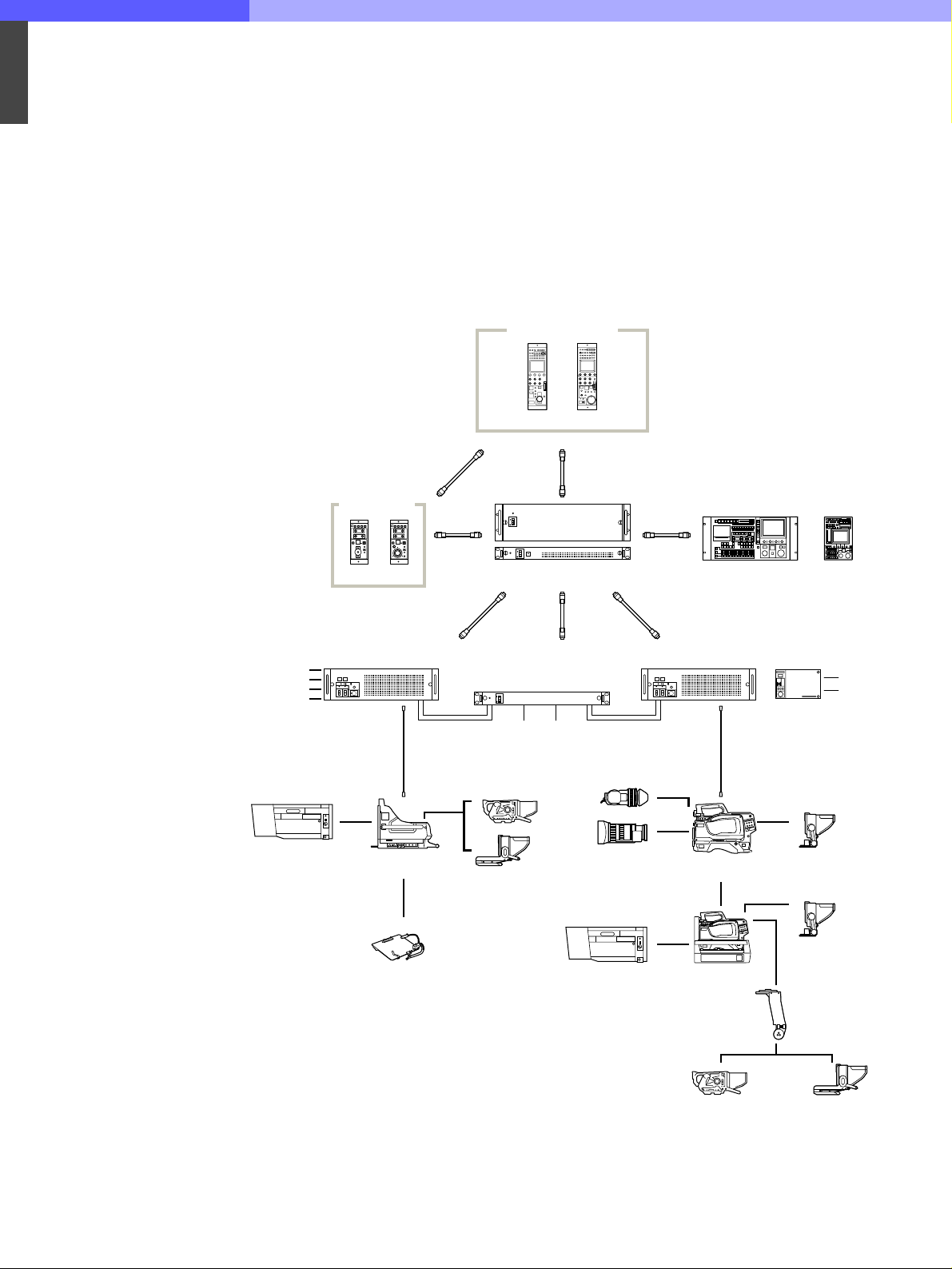
2-1. System Configuration
As a major design criteria, the HDC-900 Series
inherited all the benefits from Sony digital camera
systems such as the BVP-900/700/500 Series to
ensure the HDC-900/950/930 Family to be smoothly
integrated into these renowned, field-proven camera
control systems.
This new camera system features two camera
heads, the HDC-900 full-size model and its full
companion portable camera, the HDC-950/930. The
Figure 2-1: HDC-900/950 System Configuration
REMOTE CONTROL PANEL
RCP-750 RCP-751
REMOTE
CONTROL PANEL
CCA-5 CABLE
RCP-700 RCP-701
CAMERA COMMAND NETWORK UNIT
CNU-700/500
portable model is designed for full integration into an
HDC-900 studio system, as well as being used as a
standalone acquisition camera.
In addition to the new peripherals such as HDCU900/950, RCP-750/751, and RM-B750, a variety of key
peripherals like the CNU-700 and CNU-500 Camera
Command Network Units help users to easily expand/
upgrade their systems.
CCA-5 CABLECCA-5 CABLE
CCA-5 CABLE
MASTER SETUP UNIT
MSU-700A
MASTER SETUP UNIT
MSU-750
HKCU-901
HKCU-902
HKCU-903
HKCU-904
STUDIO ZOOM LENS
CAMERA CONTROL UNIT
HDCU-900
FIBER CABLE FIBER CABLE
COLOR VIDEO CAMERA
HDC-900
SCRIPT HOLDER
BKP-7911
CCA-5 CABLE
VIDEO SELECTOR
VCS-700
PIX
WF
ELECTRONIC VIEWFINDER
LCD COLOR VIEWFINDER
WF PIX
MULTI FORMAT
HDVF-700A
MULTI FORMAT
HDVF-C700W
CCA-5 CABLE CCA-5 CABLE
CAMERA CONTROL UNIT
HDCU-900
PIX
WF
2" VF
HDVF-20A
ENG/EPP LENS
STUDIO ZOOM LENS
COLOR VIDEO CAMERA
LARGE LENS ADAPTER
HDC-950/930
CA-905L
CAMERA CONTROL UNIT
HDCU-950
MULTI FORMAT
LCD COLOR VIEWFINDER
HDVF-C750W
MULTI FORMAT
LCD COLOR VIEWFINDER
HDVF-C750W
7-TYPE
VIEWFINDER
SADDLE
BKP-9057
HKCU-951
HKCU-953
MULTI FORMAT
ELECTRONIC VIEWFINDER
HDVF-700A
Chapter 2 Total System 14HDC-900/950/930 Series Product Information Manual
MULTI FORMAT
LCD COLOR VIEWFINDER
HDVF-C700W
Page 15
2
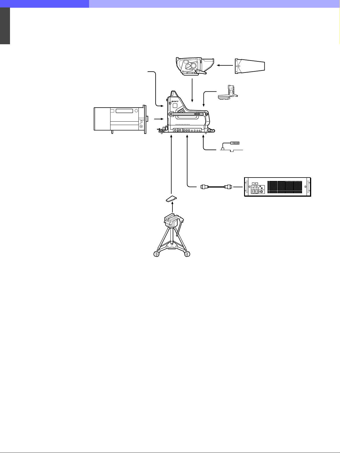
Figure 2-2: Optional Accessories for the HDC-900
Front cover (supplied)
Zoom lens
V-Shaped wedge
(supplied with tripod)
HDVF-700A 7-Type Viewfinder
(with standard hood)
HDC-900, HDC-900/L
HD Color Video Camera
Optical Fiber Cable (option)
HFH-770 Outdoor Hood
(sold separately)
HDVF-C700W
6-T ype Viewfinder
BKP-7911 Script Holder
(with Light)
HDCU-900
HD Camera Control Unit
Tripod
Chapter 2 Total System 15HDC-900/950/930 Series Product Information Manual
Page 16
2
1
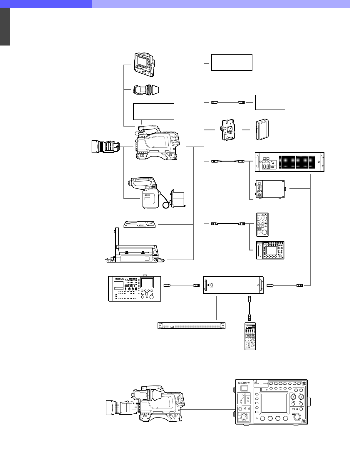
Figure 2-3: Optional Accessories for the HDC-950/930
Zoom lens
HDVF-C750W
HD Electronic
Viewfinder
HDVF-20A
HD Electronic
Viewfinder
BKW-401
Viewfinder
Rotation Bracket
HDC-950/930 HD
Color Video Camera
HKC-T950
VCT -14 Tripod Adapter
CAC-6 Return
Video Selector
HDCZ-10/25
Connection Cable
BKP-L551
Battery Adapter
Optical Fiber Cable
CCA-5 Cable
HD VTR
HDW-250, etc.
BP-L60A/L90A
Battery Pack
HDCU-900 HD Camera Control Unit
HDCU-950
HD Camera Control Unit
RM-B150
Remote
Contorl Unit
CA-905L Large Lens Adapter
MSU-700A//750 Master Setup Unit
HDS-X3400 Multi Bit Rate Routing Switcher
Figure 2-4: HDC-950 Stand-alone System
HDC-950/930 + HDVF-20A HDCU-950 + RM-B750 Remote Control Unit
CCA-5 Cable
(max. 200 meters)
IO
CNU-700 Camera
Command Network Unit
CABLE
POWER
ALRAM
CAM
OPEN
MAIN
SHORT
ONMIC
INCOM
PROD
OFF PRIV
ENGPGM
VTR
STANDARD TEST BARS CLOSE
PANEL
START/STOP
ACTIVE
MEMORY
STICK
ABB
AWB
WHITE
MONITOR
FUNCTION
BLACK
VF DISP
MAINTENANCE
VF MENU
SCENE
IRIS/MB
CANCEL
AUTO
MASTER
ACTIVE
IRIS
BLACK
PAINT
EXT
ENTER
IRIS
ALARM
MENU SELECT
REMOTE CONTROL UNIT RM-B750
RM-B750
CCA-5 Cable
(max. 200 meters)
CCA-5 Cable
(max. 200 meters)
RCP-700 series
Remote Control Panel
PANEL
STANDARD MONITOR TEST BARS
ACTIVE
MEMORY
5600K AUTO
SKIN
BLACK
KNEE
DETAIL
GAMMA
FUNCTION
STICK
MAINTE
NANCE
SCENE
PAINT
ALARM
CLOSE
KNEE
SATURATION
AWB
WHITE
ABS
BLACK
AUTO
IRIS/MB
IRIS
ACTIVE
EXT
IRIS
REMOTE CONTROL UNIT
START/STOP
VTR
ABB
MASTER
BLACK
Chapter 2 Total System 16HDC-900/950/930 Series Product Information Manual
Page 17

2
2-2. Camera Head
The HDC-900 Series is an outstanding new-generation
HD camera with a true multi-purpose system in which
many new technologies have been incorporated such
as Sony’s ADSP (Advanced Digital Signal Processing),
a newly developed 2.2-million pixel CCD and 12-bit A/
D conversion. 12-bit A/D conversion improves
gradation analysis by a factor of four compared to 10bit conversion, significantly improving control over
picture tonal reproduction, and accuracy of color
reproduction. A 600% dynamic range in conjunction
with the 12-bit A/D and the superior DSP processing
ensure superb processing of overexposed picture
information and the handling of specular highlights.
Just some of the state-of-the-art features are:
• Optical filter wheels
• Multiple output capability
• Optical fibre digital transmission
• Memory Stick
• Triple skin tone detail
• Adaptive detail control
• Electronic soft focus
• Adaptive highlight control
• Knee saturation
• Multi matrix control
These improvements contribute to an unsurpassed
image quality, making the HDC-900 Series a true ‘topof-the-line’ studio/OB camera.
The HDC-950/930 is the portable version of the
HDC-900 and has identical video processing circuitry.
Both models have the same signal performance and
can be controlled either at the camera head or by
remote control through studio system peripherals such
as the HDCU-900/HDCU-950 Camera Control Unit,
MSU-700A/750 Master Set-up Unit and CNU-700/500
Camera Command Network Units. Because of this
design concept, users of the HDC-950/930 have the
same features, the same operational performance and
the same operational ‘feel’ as the HDC-900 - an
optimized solution to meet the needs of high-end users
for a companion studio portable camera.
The flexible interfacing of the HDC-900 and HDC-
950/930 means that they are not only high-end HD
broadcasting cameras, but they can also be easily
integrated into conventional studio/OB vehicle
systems that use earlier BVP-900/700/500 Series
cameras.
The HDC-900/950 family has the following features:
High picture quality and high performance
The new 2/3-type 1080 FIT CCD with 2,200,000 pixels,
a unique CCD output signal processing circuit, and a
12-bit A/D converter provide high picture quality and
excellent performance for the HDC-900 and HDC-950.
A high-cost-performance IT type - HDC-930 - is also
available.
Newly designed integrated unit (HDC-950/930 only)
Low power consumption and high efficiency of heat
radiation were -addressed by integrating the camera
and camera adapter into a single unit, improving the
reliability. In addition, five filter discs each for CC and
ND are provided as standard to match the operability
of the studio-use HDC-900.
Multiple formats
The HDC-900 and HDC-950 operate with various
formats, covering 24PsF, 50i, 25PsF, 30PsF, as well as
60i systems, while the HDC-930 operates with 50i and
60i systems.
(media card operation)
*1
Memory Stick
The camera is equipped with a Memory Stick drive,
which enables setup data storage and software
upgrading using Memory Stick media cards.
*1 “Memory Stick” is a trademark of Sony Corporation.
Selection of gamma table
Multiple gamma tables are provided, enabling you to
use multiple formats and perform flexible image
creation.
Wide variety of detail control functions
Skin tone detail function
Allows control (emphasis or suppression) of the detail
level for just a certain hue or chroma area in the image,
by creating a detail gate signal from hue color
components centered on skin tones. Detail boost
frequency control
The boost frequency can be adjusted from 20 MHz to
30 MHz. This allows the detail thickness to be set
appropriately for the subject, thus enabling more
subtle image expression.
H/V ratio control
The ratio between horizontal and vertical detail can be
adjusted.
White/black limiter
The white side and black side detail can be limited
independently.
Easy menu-based setting
Selections and settings for shutter speed, ECS, Super
EVS mode, viewfinder display items, video gain, safety
zone marker
etc. may be made quickly and easily using setup
menus displayed on the viewfinder screen or an
external monitor.
*2 Safety zone marker: A box-shaped marker displayed on
the viewfinder sc reen which indicates 80%, 90%, 92.5% , or
95% of the total screen area.
*3 Center marker: A cross-shaped marker that indicates the
center of the viewfinder screen.
Wide variety of viewfinder display options
Along with items such as operation messages, a zebra
*4
pattern
camera settings may also be displayed on the
viewfinder screen using text and symbols. Further,
there are other indicators arranged above and below
the viewfinder, such as a tally lamp, battery warning
indicator, and an indicator to tell that one or more
settings are other than standard. This makes it simple
to check the status of the camera.
*4 Zebra pattern: A stripe pattern displayed o n the viewfinder
screen which indicates the portions where the video level
is above about 7 0% or 100%. Used to check the video level
of the subject.
Optical digital transmission
The camera uses electro-optical composite cable for
1.5-gigabit digital optical transmission between the
camera and a camera control unit.
High-resolution 2-type multi-format viewfinder (HDC950/930 only)
Along with developing the HDC-950, a 2-type multiformat viewfinder HDVF-20A is provided.
Prevention of electrical shock
When the power connection is unsafe, the power
supply from the HDCU (Camera Control Unit) will be
shut off.
operation
*2
or center marker*3, screen size marker,
, a safety zone marker, and a center marker,
Chapter 2 Total System 17HDC-900/950/930 Series Product Information Manual
Page 18

2
Wide variety of input and output connectors
• Optical connector
• HD SDI output connector
• DC power supply input connector
• Prompter signal output connector
• RCP connector
• VTR connector
• Lens connector
2-3. Camera Control Unit
• Viewfinder connector
• Intercom connector
• Analog audio input connectors
• Tracker connector
• Test output connector
• Return control connector
• AC OUT connector
• Large lens connector
The HDCU-900 Camera Control Unit carries out signal
processing and offers an interface for external
equipment. By incorporating a optical digital
transmission and digital control system, as well as
multiple inputs and outputs, the HDCU-900 provides
maximum camera performance combined with flexible
operation. It has been designed to achieve the highest
reliability, afford easy maintenance and allow flexible
system configuration.
The HDCU-900 features a down converter to convert
*1
signals to SD*2, and a return video up converter
HD
to convert SD signals to HD, making it usable with
standard definition color video cameras as well as
high-definition color video cameras. It can be
combined with an optional MSU-700A/750 Master
Setup Unit or an optional RCP-750/751/700/701
Remote Control Panel to form a camera control system
that meets your system needs. Furthermore, a system
capable of controlling multiple video cameras can also
be -configured - by adding a CNU-700/500 Camera
Command Network Unit.
*1 High Definition (HD) signal: A name for 1125-line high-
definition TV signals.
*2 Standard Definition (SD) signal: A name for NTSC/PAL,
525/625 component, or 525/625 composite signals.
The HDCU-950 Camera Control Unit is also
available for use with the HDC-950 and HDC-930
cameras. Its compact body and multiple video outputs
make this unit ideal for field use. A stand-alone system
can be easily configured by attaching the control
panel of the RM-B750 Remote Control Unit to the
HDCU-950, which allows you to directly operate the
connected camera from the HDCU-950.
The HDCU-900 and HDCU-950 camera control units
have the following major features:
Multiple video inputs and outputs (HDCU-900 only)
The HDCU-900 has four sets of HD-SDI (Serial Digital
Interface) signal inputs and outputs, and four sets of
SD component SDI signal inputs and outputs. Adding
of various optional function boards allows the following
signal input and output:
HKCU-901 SD Analog Interface board
This provides the capability of PAL, NTSC, and SD
analog component signal input and output.
HKCU-902 HD Analog Interface board
This provides HD analog signal input and output.
HKCU-903 Frame Rate Converter board
This provides 60i-/50i-format output in a 24P Cinema
Production system.
HKCU-904 Line Converter board
This provides 720/60P input and output.
Multiple video outputs (HDCU-950 only)
The HDCU-950 has three HD-SDI (Serial Digital
Interface) signal outputs (2 regular outputs and 1
monitor output) and two SD component SDI signal
outputs. Adding the optional units allows the following
signal outputs:
HKCU-951 SD Encoder board
This provides the capability of NTSC (or PAL) SD
analog component signal output.
HKCU-953 HD Frame Rate Converter board
This provides 60i-/50i-format HD and SD signal
outputs in a 24P Cinema Production system.
Three return video inputs (HDCU-950 only)
The HDCU-950 has three return video input
connectors, which receive either HD SDI, SD
component SDI or analog VBS signals (mixed input of
different signals is not allowed), may be set to 4:3 edge
crop, 16:9 squeeze, or letterbox.
External reference signals
The HDCU-900/950 family can be locked to an
external reference signal. Either an HD tri-level sync
signal or an SD sync (black burst) signal may be used
as the reference signal.
Internal down converter
When the system is operating at a 59.94/50 Hz field
frequency, HD signals can be converted to SD
component SDI signals using the down converter. The
output signal aspect ratio may be set to 4:3 edge crop,
16:9 squeeze, or letter box. The down converter has
independent image enhancement, gamma control,
and matrix ON/OFF features, and can be controlled
externally.
Internal up converter
The HDCU-900/950 family has an up converter to allow
monitoring of SD signal return video using an HD
viewfinder. The aspect ratio of the return video signal
may be set to 4:3 edge crop, 16:9 squeeze, or letter
box.
Optical digital transmission
The HDCU-900/950 can be connected to a camera
with the use of an optical fiber cable (two single-mode
optical fiber lines, two power lines, two control lines) for
the transmission of digitized video, audio, and control
signals. By connecting optical fiber cables, signals
can be transmitted up to a maximum of 3000 meters
(1.86 miles) when using the HDCU-900 and up to 1200
meters (0.7 mile) using the HDCU-950. The maximum
length of the cable supplying power to the camera
varies with the camera system configuration and with
the type of optical fiber cable.
Safety-oriented power supply
The HDCU-900/950 is designed for safety. When the
power is turned on, a low voltage is supplied at first.
Only after it has been verified that an appropriate
camera is attached, the normal 240 V power supply is
activated. The power is not supplied unless a camera
is connected via an optoelectric cable.
Also, the HDCU-900/950 is equipped with an alarm
indicator to warn of open or short circuits in the cable.
Chapter 2 Total System 18HDC-900/950/930 Series Product Information Manual
Page 19

2
Wide range of audio functions
The HDCU-900/950 family has connectors for twochannel microphone outputs, a digital audio output,
and a program audio input. The family can use an
intercom system with two independent channels, and
supports four-wire and RTS intercom systems. Further,
a Clear-Com system can also be supported.
Note
For information on support for RTS systems, contact a
Sony service or sales representative.
Character signal output
The results of the HDCU-900/950 self-diagnosis can
be obtained with a text display by an SD character
signal output.
Rack mountable
The HDCU-900 can be installed in a full 19-inch rack of
3U height, while the HDCU-950 can be installed in a
half 19-inch rack of 3U height in combination with the
RMM-301.
Remote control
The levels and phases of the HDCU-900/950 output
signals can be controlled remotely by an MSU-700A/
750 Master Setup Unit.
Microphone volume control
The camera’s microphone volume can be controlled
via the MIC REMOTE connector.
2-4. Control System
In addition to the MSU-700A/750 Master Set-up Unit
and several types of RCP-700 Series Remote Control
Panels, the CNU-700 and CNU-500 Camera
Command Network Units form the command nerve
center for a new concept in a camera control system.
A wide selection of control peripherals allows each
user to configure the most suitable system to meet a
specific operational need. The following are the key
peripherals.
Master Set-up Unit (MSU-700A and MSU-750)
The MSU-700A/750 Master Set-up Unit can control up
to 6 cameras (up to 12 cameras by using an expansion
board - BKP-7930) in combination with the CNU-700
Camera Command Network Unit. The adoption of an
EL Touch Panel in the MSU-700A/750 helps to simplify
the operation of its sophisticated control system. Data
such as scene files can be stored in a world-standard
PCMCIA memory card.
Camera Command Network Units (CNU-700 and
CNU-500)
The Camera Command Network Units are designed to
be the nerve center of the Sony camera control system
for the newly developed HDC-900/950/930 family and
the conventional BVP-900/700/500 SD Series of
cameras. They work as ‘Command Selector’,
‘Command Distributor’ and ‘Command Arbitrator’.
These two types of camera command network units
give a cost/performance choice. The CNU-500 is
suitable for applications with up to six cameras, while
the standard six-camera capability of the CNU-700
can be expanded to 12 cameras with use of the BKP7930 optional expansion board. The carefully
designed software and the high-speed CPU of both
Plug-in unit configuration
Internal printed circuit boards used in the HDCU-900/
950 are designed for easy plug-in and removal for
easy inspection and maintenance. Furthermore, the
power supply housed in the HDCU-900 is also a plugin type unit.
the CNU-700 and CNU-500 give them a fast response
time whatever the system configuration.
Video Selector (VCS-700)
The VCS-700 Video Selector is used to switch
composite video monitoring signals from an HDC-900
Series multi-camera system to a picture monitor and
waveform monitor. The VCS-700 accepts the video
monitoring signal from up to six HDCU-900 or HDCU950 Camera Control Units and switches these signals
to two picture monitor outputs and two waveform
monitor outputs. The selection of monitoring signals
can be controlled by the camera selection buttons on
the MSU-700A/750 Master Set-up Unit, or by external
control equipment through the D-sub 37-pin I/O port
on the VCS-700. For SDI monitoring, the optional BKP7933 S-Bus Interface Board provides connection to a
Sony digital routing system.
Remote Control Panels (RCP-700 Series)
There are four ranges of remote control panels for
remote control of the HDC-900 Series via the HDCU900/950 Camera Control Unit. For the iris and master
black adjustments, each range has two types - joystick
control and dial control.
The RCP-750/751 is the newly developed, top of the
range for sophisticated operational use, and can be
used as a substitute for the MSU-700A/750 Master Setup Unit. The panel is connected to the HDCU-Series
Camera Control Unit (or the CNU-Series Camera
Command Network Unit, which is connected to the
HDCU-Series) by a special cable of up to 200 m (656
ft) in length.
The RCP-700/701 features the basic control items
required for daily operation of camera acquisition
systems.
2-5. Viewfinders
As well as the HDVF-700A, a high performance 7-type
multi-format electronic monochrome viewfinder with
extremely high horizontal resolution, the HDVF-C700W
6-type multi-format LCD color viewfinder is also
available for the HDC-900. This multi-format LCD color
viewfinder is especially convenient for cases where
color needs to be identified by the camera operator.
For the HDC-950, the HDVF-C750W - a 6-type multiformat LCD color viewfinder and the HDVF-20A - a 2-
type HD monochrome electronic viewfinder are newly
designed, which fulfill the requirement for different
applications.
All of these models are very compact in size, light in
weight and economical in power consumption. The low
mounting positions of the HDVF-700A and HDVFC700W provide convenient viewfinder displays
aligned as close as possible to the lens axis.
Chapter 2 Total System 19HDC-900/950/930 Series Product Information Manual
Page 20

2
The HDVF-700A has the following features:
Multiscan
In addition to the 60i format, formats such as 24PsF
and 50i are supported for control signals from the
camera.
16:9 display capability
When operated from an external device such as a
camera control unit, the screen can be switched
between 16:9 and 4:3 display modes.
High resolution
The viewfinder uses a high-resolution cathode-ray
tube, providing 800 or more lines of horizontal
resolution.
Stable picture
A high-voltage regulation circuit provides a stable
image with a minimum of distortion, regardless of
screen brightness.
Continuously variabl e pe a ki ng
A continuously variable peaking circuit provides a
sharp image, making it easy to focus the camera.
Tally lamps
The viewfinder has red and green tally lamps which
light in response to tally signals.
Superior usability
The viewfinder height may be set to one of three
positions, and it may be tilted up to 60° upwards or 50°
downwards.
Drip-proof construction
The drip-proof design is able to withstand light rain,
making the viewfinder well suited to outdoor use.
Studio monitor hood, outdoor hood
The viewfinder may be fitted with a strong, easy-to-use
studio hood (supplied), or an outdoor broadcasting
(OB) hood with excellent shading ability (option).
Energy-saving design
The viewfinder will accept a wide range of power
supply voltage (from 10.5 to 17 volts) with low power
consumption (33 watts).
The HDVF-C750W/C700W has the following features:
Compact and lightweight
The viewfinder uses an LCD panel, making it more
compact in size and lighter in weight as compared with
a CRT viewfinder that has a display of the same size.
Multiscan
In addition to the 60i format, formats such as 24PsF
and 50i are supported for control signals from the
camera.
High resolution
The high-resolution LCD panel of the viewfinder
provides 500 or more lines of horizontal resolution.
Stable picture
The LCD panel provides a stable image without
distortion, regardless of screen brightness.
Step-variable peaking
Step-variable peaking circuits provide a sharp image,
making it easy to focus the camera.
Tally lamps
The viewfinder has red and green tally lamps which
light in response to tally signals.
Superior usabili ty
The height of the HDVF-C750W can be set to one of
three positions. It can be tilted up to 90° upwards or
90° downwards, and can be panned up to 90° -to the
left or 90° -to the right. The HDVF-C700W can be tilted
up to 90° upwards or 50° downwards.
Drip-proof construction
The drip-proof design is able to withstand light rain,
making the viewfinder well suited to outdoor use.
Studio monitor hood, outdoor hood
The viewfinder can be fitted with a strong, easy-to-use
hood (supplied), or an outdoor hood with excellent
shading ability (option).
Energy-saving design
The viewfinder will accept a wide range of power
supply voltage (from 10.5 to 17 volts) with low power
consumption (10 watts).
The HDVF-20A has the following features.
Multiscan
In addition to the 60i format, formats such as 24PsF
and 50i are supported for control signals from the
camera.
High-performance CRT
• Quick-start type (The image appears as soon as the
camera is turned on.)
• Enhanced resolution
• Reduced flare
Marker indication
When the camera setting allows the center marker or
safety zone marker indication, the viewfinder can set
the marker indication on or off.
Removable eyepiece
Detaching the eyepiece gives you a clear view of the
center of the screen even with your eye away from the
viewfinder. You can clean dust from the screen or the
mirror by detaching the eyepiece.
Other features
Fitting an optional fog-proof filter (Part No. 1-547-341-
12) over the viewfinder lens prevents breath or vapor
condensation on the lens.
2-6. Optional Accessories
For HDC-900
HDVF-700A HD Electronic Viewfinder
HDVF-C700W HD Electronic Viewfinder
VFH-770 Outdoor Hood
BKP-7911 Script Holder (with script
CAC-6 Return Video Selector
EX-738(A-8327-351-A) Extension Board
For HDC-950/930
BKP-L551 Battery Adaptor
BKW-401 Viewfinder Rotation
C-74 Microphone
CA-905L Large Lens Adaptor
CAC-6 Return Video Selector
CAC-12 Microphone holder
(7-type, monochrome)
(6-type, color)
light)
Bracket
CRS-3P Cradle Suspension
HKC-T950 CCD Block Extension
Adaptor
HDVF-20A HD Electronic Viewfinder
HDVF-C750W HD Electronic Viewfinder
MSA-8A/16A /32A/64A Memory Stick Media
Card
VCT-14 Tripod adaptor
EX-738(A-8327-351-A) Extension Board
For HDCU-900
AC power cord: USA and Canada: 1-
551-812-XX
Other countries: 1-782-
929-XX
Power cord plug holder:USA and Canada: 2-
990-242-01
Other countries: 3-613-
640-01
Chapter 2 Total System 20HDC-900/950/930 Series Product Information Manual
Page 21
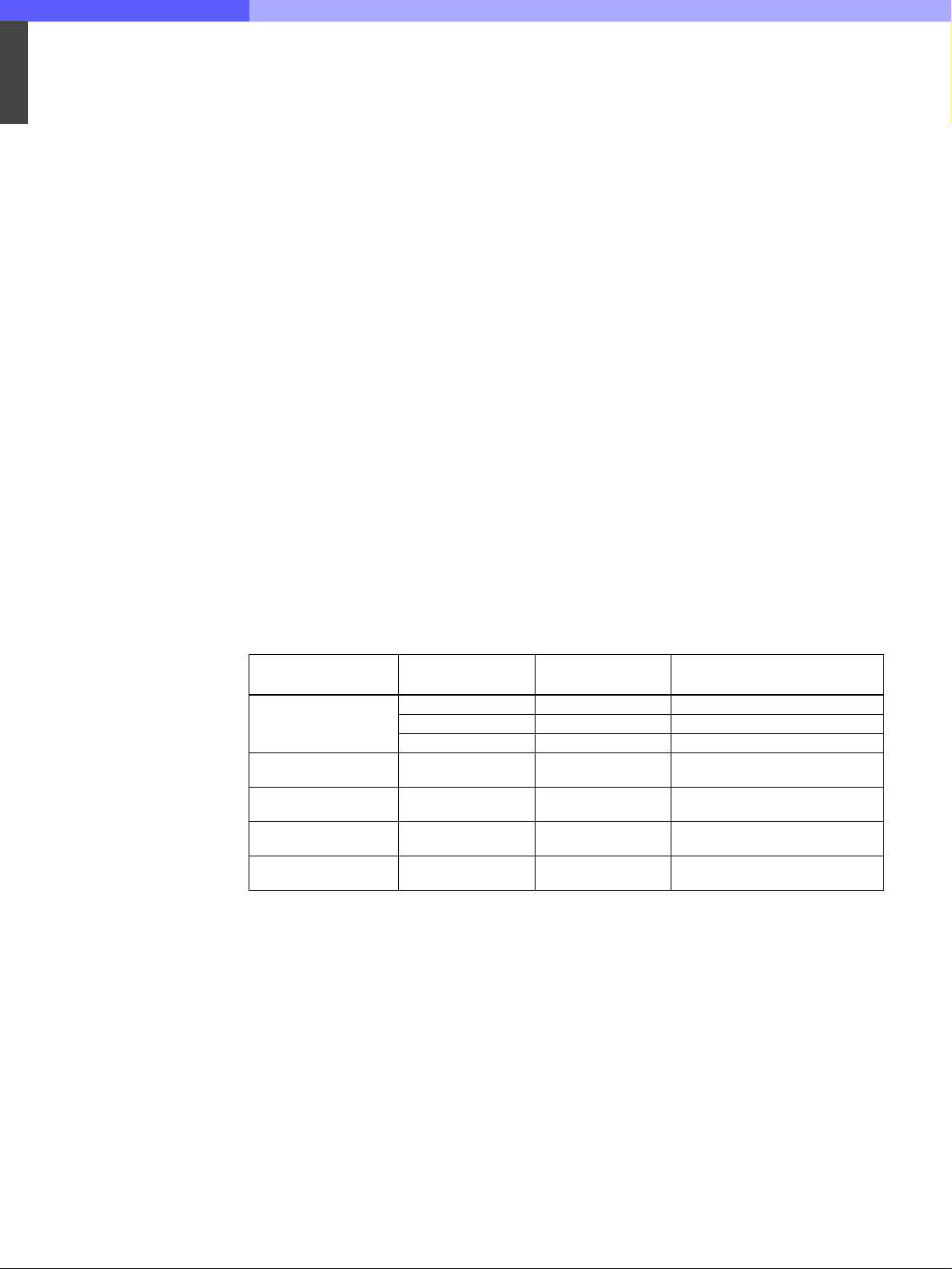
2
HKCU-901 SD Analog Interface Unit
HKCU-902 HD Analog Interface Unit
HKCU-903 Frame Rate Converter
HKCU-904 Line Converter Unit
CCA-5-3 Connection Cable (3
CCA-5-10 Connection Cable (10
EX-450(A-8314-633-A) Expansion Board
For HDCU-950
AC power cord: USA and Canada: 1-
Power cord plug holder:USA and Canada: 2-
HKCU-951 SD Encoder Unit
HKCU-953 HD Frame Rate
CCA-5-3 Connection Cable (3
2-7. System Setup
Unit
meter/10 feet)
meter/33 feet)
551-812-XX
Other countries: 1-782929-XX
990-242-01
Other countries: 3-613640-01
Converter Unit
meter/10 feet)
CCA-5-10 Connection Cable (10
meter/33 feet)
RMM-301 Rack Mount Adaptor
EX-854(A-8344-228-A) Extension Board
EX-893(A-8344-696-A) Extension Board
For CNU/ MSU/RCP
BKP-7900 Extender Board for
CNU-700/500
BKP-7930 Expansion Board for
system expansion up to
12 cameras for the CNU-
700
BKP-7932 BVP-370 Series
Interface Board for the
CNU-700
BKP-7933 S-Bus Interface Board
for CNU-700
CCA-5 Cables 8p-8p cables for the
CNU-700/500, MSU-
700A/750, VCS-700 and
RCP-700 Series
CCA-5-3 3 m
CCA-5-10 10 m
CCA-5-30 30 m
2-7-1 Setting the System Format using
HDCU-900
The HDCU-900 can support input and output of
multiple formats. It can also support various types of
user’s format by installing the optional circuit boards.
HDCU-900 and list of optional boards
Model name
HDCU-900
SD Analog Interface Unit
HKCU-901
HD Analog Interface Unit
HKCU-902
Frame Rate Converter
Unit HKCU-903
Line Converter Unit
HKCU-904
*1 for the USA and Canada.
*2 for the countries other than the USA and Canada.
Note
• Be sure to install the HKCU-901 of the same -regional
location as the HDCU-900.
• When the HKCU-901 is going to be installed, confirm
beforehand that the RC-86 board is installed in the
second slot from the top on the front side, the DIF102 board or the HKCU-902 is installed in the second
slot from the top on the front side.
• When installing the optional boards, be sure to start
installation from the second slot from the top on both
the front side and rear side. Never install an optional
board in the third slot from the top leaving the slots
blank without installing the board.
• Be sure to install the HKCU-901/903/904 into the
same slot on the front and rear sides.
• Do not install two or more of the same circuit boards
at the same time.
Board name
(Slots on the front)
DPR-163 SDI-54A Fixed to the top most slot
RC-86 DIF-102 Second or third slot from the top
AT-141 – Fixed to the bottom most slot
*1
*2
IF-789A
– ADA-59 Second or third slot from the top
FC-83 SDI-54B Second slot from the top
LC-41 SDI-54C Second or third slot from the top
/789P
VDA-57 Third slot from the top
The slots to which the circuit boards are inserted and
the internal switches of the unit differ depending upon
the system used. They need to be set according to the
system used.
Board name
(Slots on the rear)
Slot to be installed
Chapter 2 Total System 21HDC-900/950/930 Series Product Information Manual
Page 22
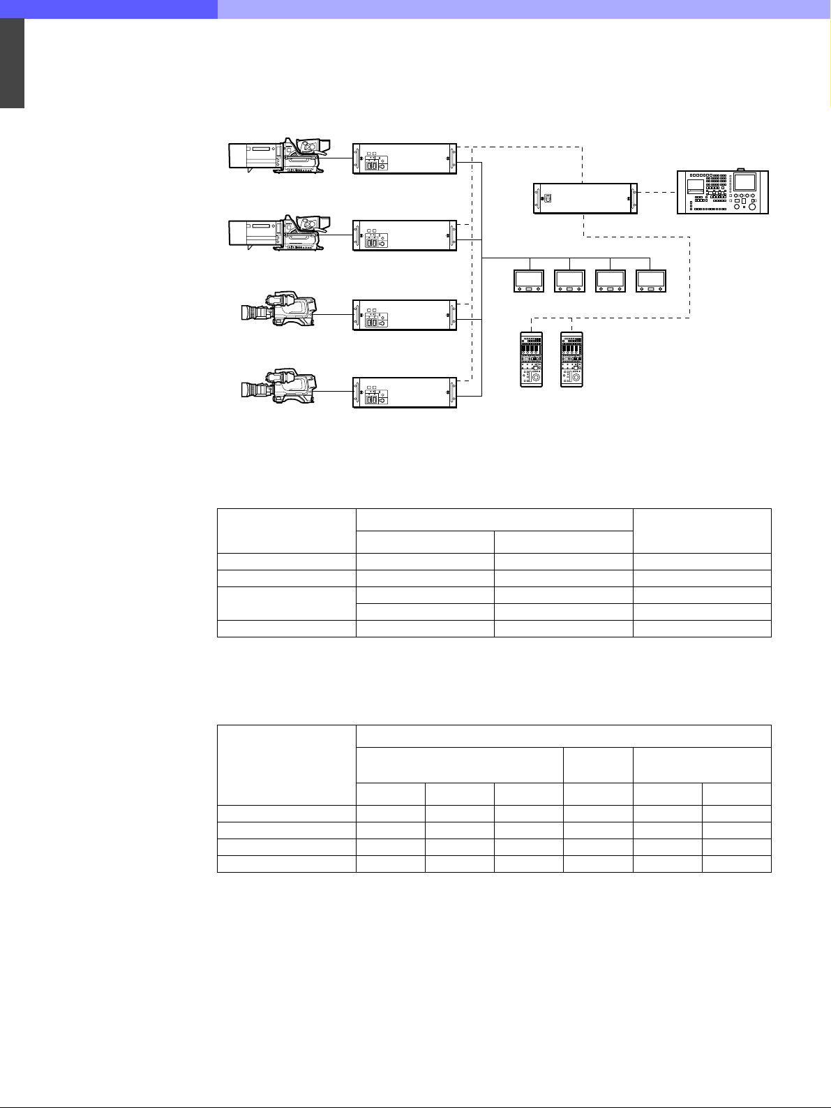
2
2-7-1-1 HD System
HDC-900
HDC-900
HDC-950
HDC-950
HDCU-900
HKCU-901
HKCU-902
HKCU-903
HKCU-904
HDCU-900
HKCU-901
HKCU-902
HKCU-903
HKCU-904
HDCU-900/950
HKCU-901/951
HKCU-902
HKCU-903/953
HKCU-904
HDCU-900/950
HKCU-901/951
HKCU-902
HKCU-903/953
HKCU-904
HD-SDI Monitor
RCP-700/701
RCP-750/751
CNU-700
MSU-700A/750
Combination of boards
System format
Combination of boards (S lots on the front)
Signal input/output slot
Second slot from the top Third slot from the top
1080/59.94I SDI RC/FC/LC/– RC/LC/IF
*1
/– Top most slot
1080/59.94I SDI Film Like FC RC/LC/– Second slot from the top
*2
1080/59.94I Analog
RC
RC/FC/LC –
1080/50I SDI RC/FC/LC/– RC/LC/IF
*1 When installing the IF-789A/789P board (HKCU-901),
confirm that the RC-86 board is installed in the second slot
from the top.
IF/– Second slot from the top
*3
*1
/– Top most slot
*2 The second slot from the top on the rear side must have the
ADA-59 board (HKCU-902) installed.
*3 The third slot from the top on the rear side must have the
ADA-59 board (HKCU-902) installed.
Third slot from the top
Setting switches
Switch setting
System format
DPR-163 board (S804 : LOCAL)
AT-141
board
FC-83 board
S805 S807 S806 S603 S2 S2
1080/59.94I SDI NOT 60 Intr /1001 * *
1080/59.94I SDI Film Like NOT 48 PsF /1001 30 i
1080/59.94I Analog NOT 60 Intr /1001 * *
1080/50I SDI NOT 50 Intr /1000 * *
* -NA
Chapter 2 Total System 22HDC-900/950/930 Series Product Information Manual
Page 23
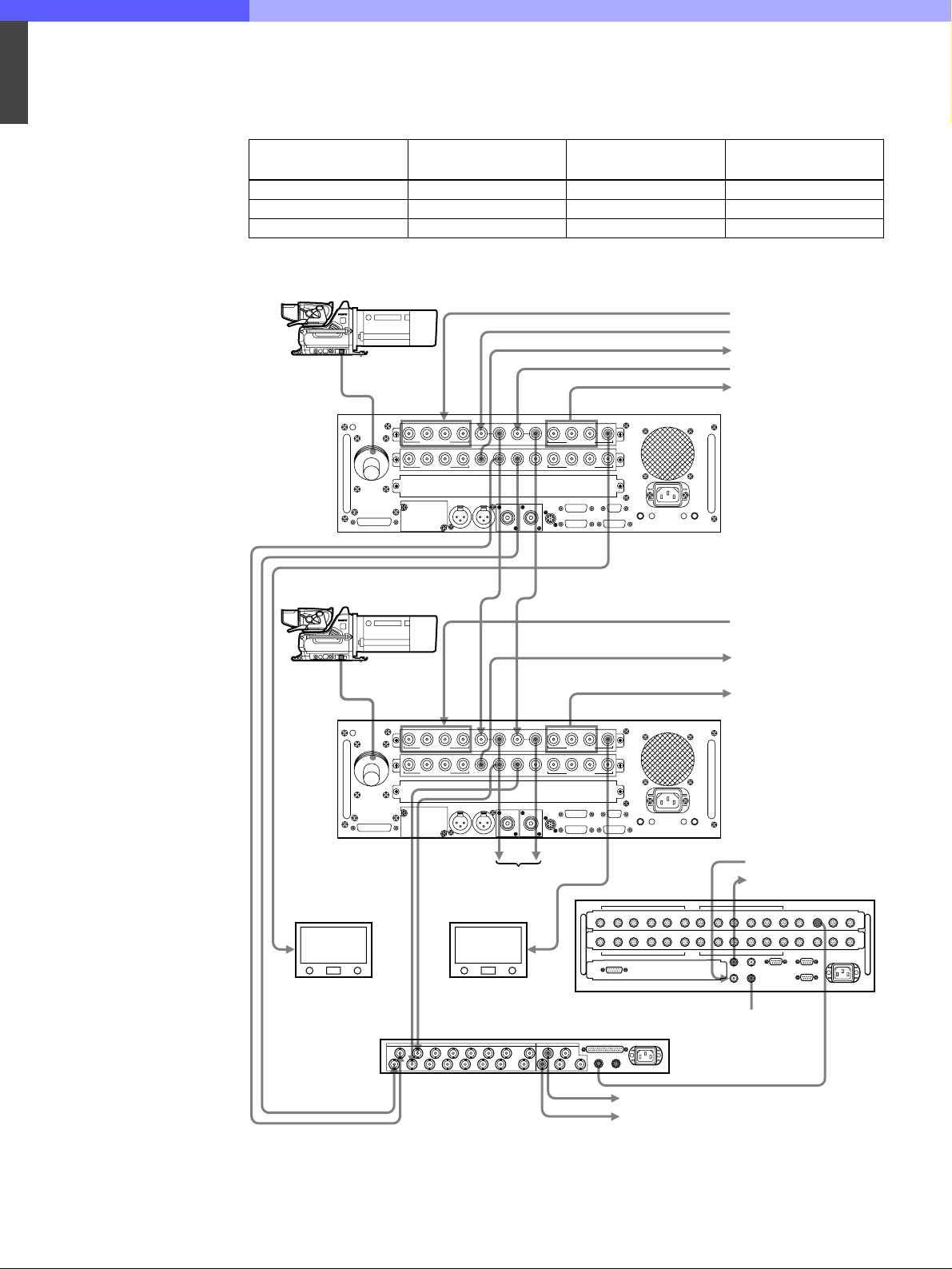
2
Figure 2-7-1-1: Example of connection using HDCU-900 (1) – System format: 1080/59.94I SDI
Required boards
Slot to be installed
Board name
(Slots on the front)
Board name
(Slots on the rear)
Remarks
Top most slot DPR-163 SDI-54A HDCU-900
Second slot from the top RC-86 DIF-102 HDCU-900
Third slot from the top Blank Blank
HDC-900
HDCU-900
123 4
123 4
REFERENCE IN PROMPTER IN
SYNC OUT
PIX OUT WF OUT WF MODE
1 2 3 MONI
SERIAL OUTPUTSERIAL RET INPUT
1234
SERIAL OUTPUTSERIAL RET INPUT
SERIAL RET INPUT 1 to 4
REFERENCE IN
SYNC OUT (HD)
PROMPTER IN
SERIAL OUTPUT 1 to 3
SERIAL RET INPUT 1 to 4
HD-SDI RETURN VIDEO SIGNAL
REFERENCE SIGNAL
HD REFERENCE SIGNAL
PROMPTER SIGNAL
HD-SDI SIGNAL
HD-SDI RETURN VIDEO SIGNAL
HDC-900
123 4
123 4
HDCU-900
HD-SDI Monitor HD-SDI Monitor
PIX 1 PIX 2
WF 2WF 1
REFERENCE IN PROMPTER IN
SYNC OUT
PIX OUT WF OUT WF MODE
Next HDCU-900
VCS-700
1 2 3 MONI
SERIAL OUTPUTSERIAL RET INPUT
1234
SERIAL OUTPUTSERIAL RET INPUT
CNU-700
PIX A
WF A
SYNC OUT (HD)
SERIAL OUTPUT 1 to 3
REMOTE
HD REFERENCE SIGNAL
HD-SDI SIGNAL
SD REFERENCE SIGNAL
SD ANALOG VIDEO SIGNAL
Terminated at 75 Ω
Chapter 2 Total System 23HDC-900/950/930 Series Product Information Manual
Page 24
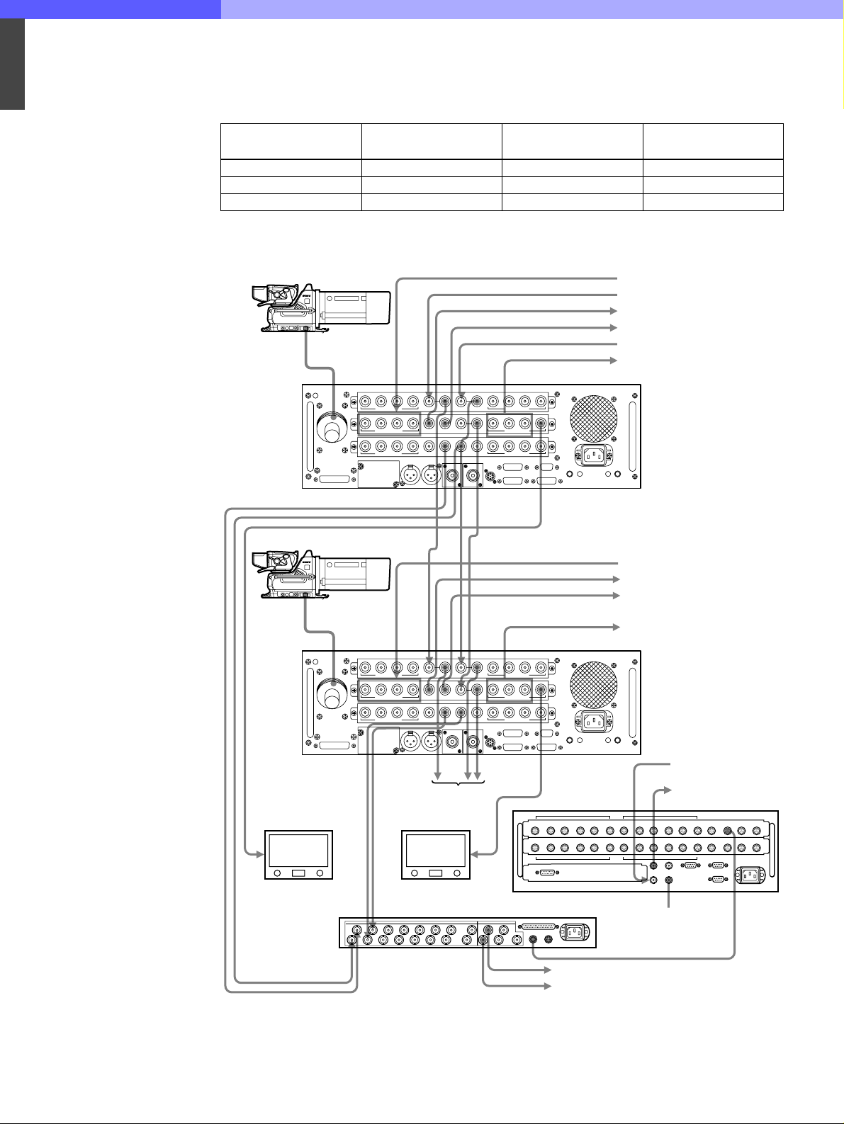
2
L
L
Figure 2-7-1-2: Example of connection using HDCU-900 (2) – System format: 1080/59.94I SDI Film Like
Required boards
Slot to be installed
Board name
(Slots on the front)
Board name
(Slots on the rear)
Remarks
Top most slot DPR-163 SDI-54A HDCU-900
Second slot from the top FC-83 SDI-54B HKCU-903
Third slot from the top RC-86 DIF-102 HDCU-900
HDC-900
HDCU-900
123 4
SERIAL RET INPUT
123 4
123 4
REFERENCE IN PROMPTER IN
SYNC OUT
SYNC OUT
FRAME REFERENCE
SYNC OUT
PIX OUT WF OUT WF MODE
SERIAL RET INPUT 1 to 4
REFERENCE IN
SYNC OUT
SYNC OUT
PROMPTER IN
SERIAL OUTPUT 1 to 3
1 2 3 MONI
SERIAL OUTPUT
1IN OUT 2 3 MONI
SERIAL OUTPUTSERIAL RET INPUT
1234
SERIAL OUTPUTSERIAL RET INPUT
HD-SDI RETURN VIDEO SIGNAL
HD REFERENCE SIGNAL
1080/29.97 PsF, tri-level SYNC SIGNA
1080/59.94I, tri-level SYNC SIGNAL
PROMPTER SIGNAL
HD-SDI SIGNAL
HDC-900
123 4
SERIAL RET INPUT
123 4
123 4
REFERENCE IN PROMPTER IN
SYNC OUT SYNC OUT
SYNC OUT
PIX OUT WF OUT WF MODE
HDCU-900
Next HDCU-900
HD-SDI Monitor HD-SDI Monitor
PIX 1 PIX 2
WF 2WF 1
VCS-700
FRAME REFERENCE
SERIAL RET INPUT 1 to 4
SYNC OUT
SYNC OUT
SERIAL OUTPUT 1 to 3
1 2 3 MONI
SERIAL OUTPUT
1IN OUT 2 3 MONI
SERIAL OUTPUTSERIAL RET INPUT
1234
SERIAL OUTPUTSERIAL RET INPUT
CNU-700
REMOTE
PIX A
WF A
HD-SDI RETURN VIDEO SIGNAL
1080/29.97 PsF, tri-level SYNC SIGNA
1080/59.94I,
tri-level SYNC SIGNAL
HD-SDI SIGNAL
SD REFERENCE
SIGNAL
SD ANALOG VIDEO
SIGNAL
Terminated at 75 Ω
Chapter 2 Total System 24HDC-900/950/930 Series Product Information Manual
Page 25
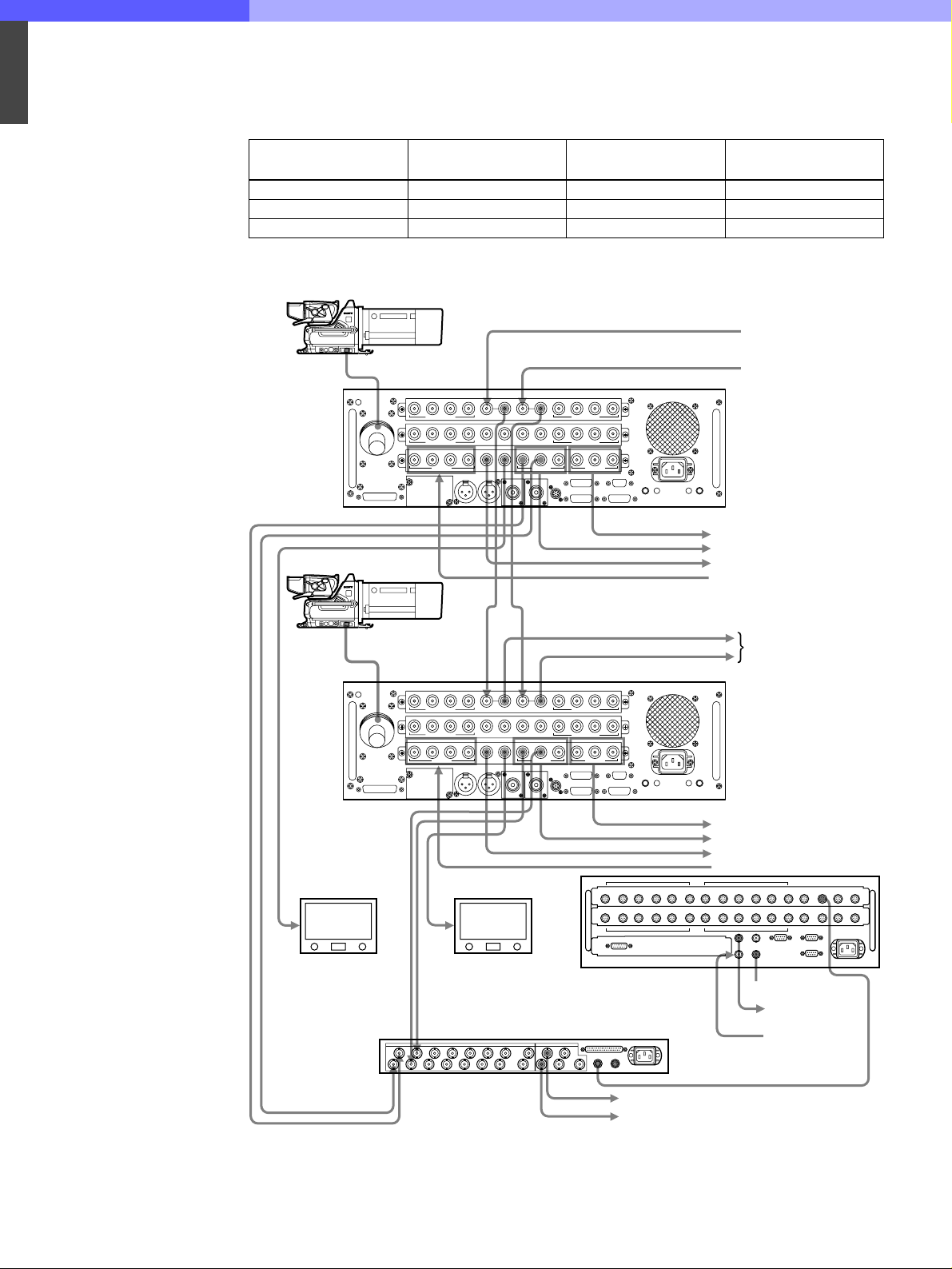
2
Figure 2-7-1-3: Example of connection using HDCU-900 (3) – System format: 1080/59.94I Analog
Required boards
Slot to be installed
Board name
(Slots on the front)
Board name
(Slots on the rear)
Remarks
Top most slot DPR-163 SDI-54A HDCU-900
Second slot from the top RC-86 DIF-102 HDCU-900
Third slot from the top Blank ADA-59 HKCU-902
HDC-900
HDCU-900
123 4
123 4
123 4 Y/GPB/B PB/BPR/R Y/G
REFERENCE IN PROMPTER IN
SYNC OUT
PIX OUT WF OUT WF MODE
SYNC OUT
PIX OUT
1 2 3 MONI
1234
OUT PUT 1 OUT PUT 2RET INPUT
SERIAL OUTPUTSERIAL RET INPUT
SERIAL OUTPUTSERIAL RET INPUT
PR/R
HD Analog Video
HD Analog Video
SYNC OUT(HD)
RET INPUT 1 to 4
REFERENCE IN
PROMPTER IN
REFERENCE SIGNAL
PROMPTER SIGNAL
HD-ANALOG VIDEO SIGNAL
HD-ANALOG VIDEO SIGNAL
HD REFERENCE SIGNAL
HD ANALOG VIDEO SIGNAL
HDC-900
123 4
123 4
123 4 Y/GPB/B PB/BPR/R Y/G
REFERENCE IN PROMPTER IN
SYNC OUT
PIX OUT WF OUT WF MODE
SYNC OUT
PIX OUT
HDCU-900
Picture Monitor Picture Monitor
PIX 1 PIX 2
VCS-700
WF 2WF 1
1 2 3 MONI
1234
OUT PUT 1 OUT PUT 2RET INPUT
PIX A
WF A
SERIAL OUTPUTSERIAL RET INPUT
SERIAL OUTPUTSERIAL RET INPUT
PR/R
HD Analog Video
HD Analog Video
SYNC OUT(HD)
RET INPUT 1 to 4
CNU-700
REMOTE
Next HDCU-900
HD-ANALOG VIDEO SIGNAL
HD-ANALOG VIDEO SIGNAL
HD REFERENCE SIGNAL
HD ANALOG VIDEO SIGNAL
Terminated at 75Ω
SD ANALOG VIDEO
SIGNAL
SD REFERENCE
SIGNAL
Chapter 2 Total System 25HDC-900/950/930 Series Product Information Manual
Page 26
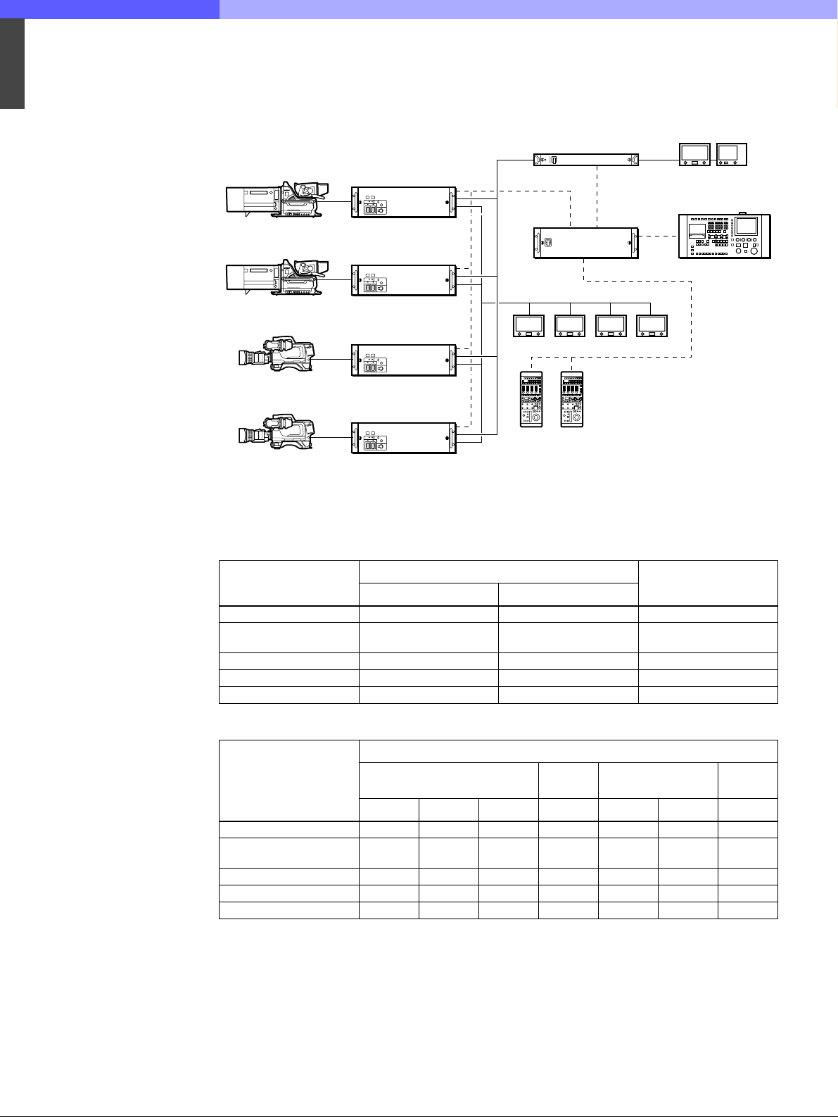
2
2-7-1-2 SD System
HDC-900
HDC-900
HDC-950
HDC-950
Combination of boards
HDCU-900
HKCU-901
HKCU-902
HKCU-903
HKCU-904
HDCU-900
HKCU-901
HKCU-902
HKCU-903
HKCU-904
HDCU-900/950
HKCU-901/951
HKCU-902
HKCU-903/953
HKCU-904
HDCU-900/950
HKCU-901/951
HKCU-902
HKCU-903/953
HKCU-904
PIX/WF
(HKCU-901)
PIX/WF (HDCU-900)
RCP-700/701
RCP-750/751
VCS-700
CNU-700
MSU-700A/750
System format
Second slot from the top Third slot from the top
Signal input/output slot
525/59.94I SDI RC LC/IF/– Second slot from the top
Combination of boards (S lots on the front)
525/29.97 PsF SDI Film
Like
FC RC Third slot from the top
NTSC RC IF Third slot from the top
625/50I SDI RC LC/IF/– Second slot from the top
PAL RC IF Third slot from the top
Setting switches
Switch setting
System format
DPR-163 board (S804 : LOCAL)
AT-141
board
FC-83 board
RC-86
board
S805 S807 S806 S603 S2 S3 S802
525/59.94I SDI NOT 60 Intr /1001 * * 525
525/29.97 PsF SDI Film
Like
NOT 48 PsF /1001 * * 525
NTSC NOT 60 Intr /1001 * * 525
625/50I SDI NOT 50 Intr /1000 * * 625
PAL NOT 50 Intr /1000 * * 625
* -NA
Chapter 2 Total System 26HDC-900/950/930 Series Product Information Manual
Page 27

2
L
Figure 2-7-1-4: Example of connection using HDCU-900 (4) - System format: 525/59.94I SDI
Required boards
Slot to be installed
Board name
(Slots on the front)
Board name
(Slots on the rear)
Remarks
Top most slot DPR-163 SDI-54A HDCU-900
Second slot from the top RC-86 DIF-102 HDCU-900
Third slot from the top Blank Blank
HDC-900
HDCU-900
123 4
123 4
REFERENCE IN PROMPTER IN
SYNC OUT
PIX OUT WF OUT WF MODE
SERIAL RET INPUT 1 to 4
REFERENCE IN
SYNC OUT
PROMPTER IN
SERIAL OUTPUT 1 to 4
1 2 3 MONI
SERIAL OUTPUTSERIAL RET INPUT
1234
SERIAL OUTPUTSERIAL RET INPUT
CHARACTER OUTPUT
SD COMPONENT SDI RETURN VIDEO SIGNAL
REFERENCE SIGNAL
SD REFERENCE SIGNAL
PROMPTER SIGNAL
SD COMPONENT SDI SIGNAL
SD ANALOG VIDEO SIGNAL
HDC-900
123 4
123 4
HDCU-900
Picture Monitor Picture Monitor
Waveform Monitor Waveform Monitor
REFERENCE IN PROMPTER IN
SYNC OUT
PIX OUT WF OUT WF MODE
Next HDCU-900
SERIAL RET INPUT 1 to 4
SYNC OUT
SERIAL OUTPUT 1 to 4
1 2 3 MONI
SERIAL OUTPUTSERIAL RET INPUT
1234
SERIAL OUTPUTSERIAL RET INPUT
CNU-700
SD COMPONENT SDI RETURN VIDEO SIGNAL
SD REFERENCE SIGNAL
SD COMPONENT SDI SIGNAL
SD REFERENCE SIGNAL
SD ANALOG VIDEO SIGNA
Terminated at 75 Ω
Chapter 2 Total System 27HDC-900/950/930 Series Product Information Manual
Page 28
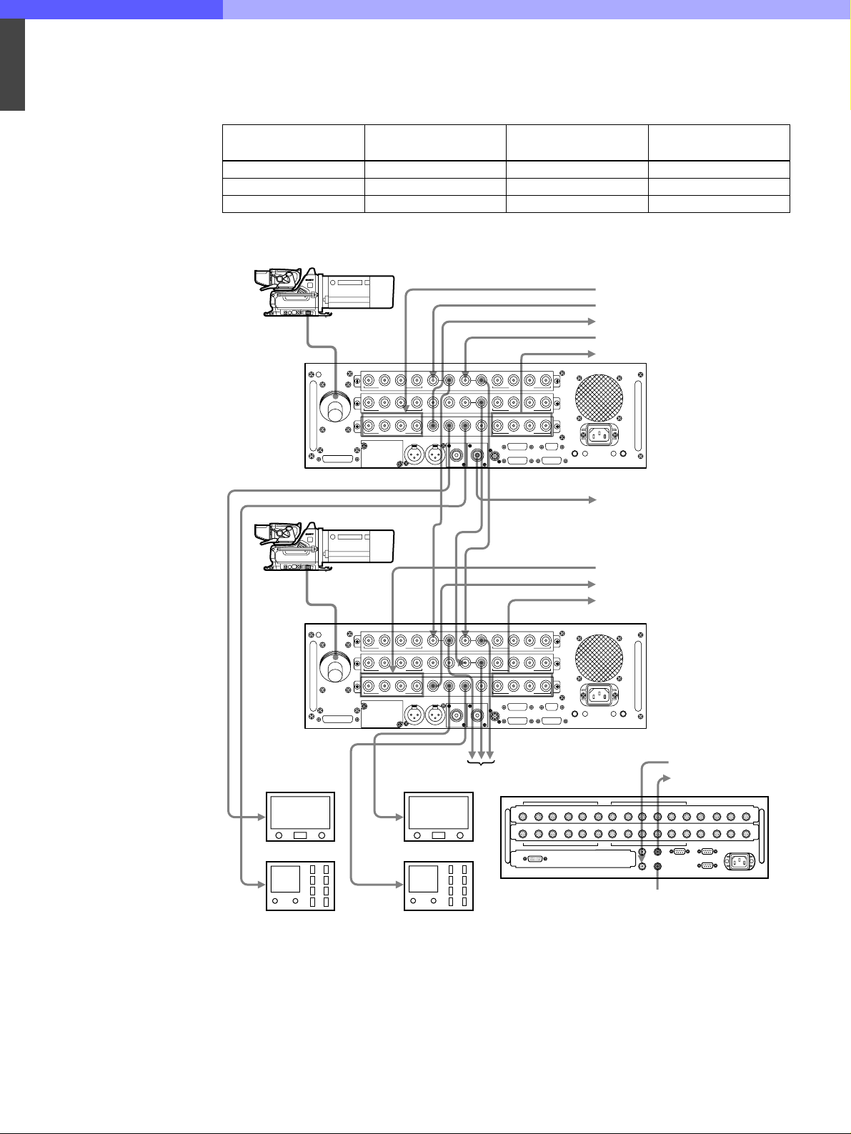
2
Figure 2-7-1-5: Example of connection using HDCU-900 (5) – System format: 525/29.97 PsF SDI Film Like
Required boards
Slot to be installed
Board name
(Slots on the front)
Board name
(Slots on the rear)
Remarks
Top most slot DPR-163 SDI-54A HDCU-900
Second slot from the top FC-83 SDI-54B HKCU-903
Third slot from the top RC-86 DIF-102 HDCU-900
HDC-900
HDCU-900
123 4
SERIAL RET INPUT
123 4
123 4
REFERENCE IN PROMPTER IN
SYNC OUT SYNC OUT
FRAME REFERENCE
SYNC OUT
PIX OUT WF OUT WF MODE
SERIAL RET INPUT 1 to 4
REFERENCE IN
SYNC OUT
PROMPTER IN
SERIAL OUTPUT 1 to 4
1 2 3 MONI
SERIAL OUTPUT
1IN OUT 2 3 MONI
SERIAL OUTPUTSERIAL RET INPUT
1234
SERIAL OUTPUTSERIAL RET INPUT
CHARACTER OUTPUT
SD COMPONENT SDI RETURN VIDEO SIGNAL
REFERENCE SIGNAL
SD REFERENCE SIGNAL
PROMPTER SIGNAL
SD COMPONENT SDI SIGNAL
SD ANALOG VIDEO SIGNAL
HDC-900
123 4
SERIAL RET INPUT
123 4
123 4
REFERENCE IN PROMPTER IN
SYNC OUT SYNC OUT
SYNC OUT
PIX OUT WF OUT WF MODE
HDCU-900
Picture Monitor Picture Monitor
Waveform Monitor
Waveform Monitor
SERIAL RET INPUT 1 to 4
SYNC OUT
SERIAL OUTPUT 1 to 4
1 2 3 MONI
SERIAL OUTPUT
1IN OUT 2 3 MONI
FRAME REFERENCE
SERIAL OUTPUTSERIAL RET INPUT
1234
SERIAL OUTPUTSERIAL RET INPUT
Next HDCU-900
CNU-700
SD COMPONENT SDI RETURN VIDEO SIGNAL
SD REFERENCE SIGNAL
SD COMPONENT SDI SIGNAL
SD REFERENCE SIGNAL
SD ANALOG VIDEO SIGNAL
Terminated at 75 Ω
Chapter 2 Total System 28HDC-900/950/930 Series Product Information Manual
Page 29
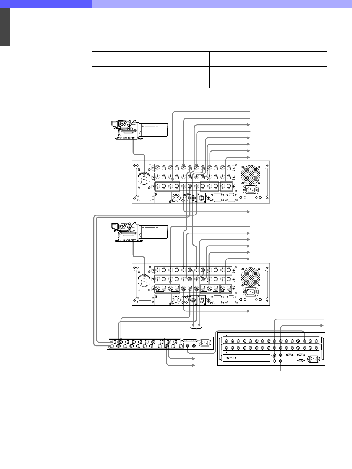
2
Figure 2-7-1-6: Example of connection using HDCU-900 (6) – System format: NTSC
Required boards
Slot to be installed
Board name
(Slots on the front)
Board name
(Slots on the rear)
Remarks
Top most slot DPR-163 SDI-54A HDCU-900
Second slot from the top RC-86 DIF-102 HDCU-900
Third slot from the top IF-789A VDA-57 HKCU-901
HDC-900
WF OUT(For MSU)
PIX OUT(For MSU)
HDC-900
HDCU-900
123 4
SERIAL RET INPUT
123 4
123 4
123 4
SERIAL RET INPUT
123 4
123 4
REFERENCE IN PROMPTER IN
SYNC OUT
PIX OUT WF OUT WF MODE
WF OUTPIX OUT
SYNC OUT
REFERENCE IN PROMPTER IN
SYNC OUT
PIX OUT WF OUT WF MODE
WF OUTPIX OUT
SYNC OUT
RET INPUT 1 to 4
REFERENCE IN
PIX OUT(For RCP)
PROMPTER IN
WF OUT(For RCP)
WF MODE(For RCP)
RGB/Component OUT
VBS OUT
1 2 3 MONI
SERIAL OUTPUT
1234
SERIAL OUTPUTSERIAL RET INPUT
R-Y/RB-Y/BY/G 1 2
VBS OUTOUTPUTRET INPUT
SYNC OUT
RET INPUT 1 to 4
PIX OUT(For RCP)
WF OUT(For RCP)
WF MODE(For RCP)
RGB/Component OUT
VBS OUT
1 2 3 MONI
SERIAL OUTPUT
1234
SERIAL OUTPUTSERIAL RET INPUT
R-Y/RB-Y/BY/G 1 2
VBS OUTOUTPUTRET INPUT
ANALOG RETURN VIDEO SIGNAL
REFERENCE SIGNAL
PICTURE MONITOR OUTPUT FOR RCP
PROMPTER SIGNAL
WAVEFORM MONITOR OUTPUT FOR RCP
WAVEFORM MONITOR MODE FOR RCP
ANALOG COMPONENT VIDEO SIGNAL
ANALOG COMPOSITE VIDEO SIGNAL
SD SYNC REFERENCE SIGNAL
ANALOG RETURN VIDEO SIGNAL
PICTURE MONITOR OUTPUT FOR RCP
WAVEFORM MONITOR OUTPUT FOR RCP
WAVEFORM MONITOR MODE FOR RCP
ANALOG COMPONENT VIDEO SIGNAL
ANALOG COMPOSITE VIDEO SIGNAL
PIX 1
WF 1
PIX 2
WF 2
HDCU-900
PIX OUT(For MSU)
WF OUT(For MSU)
VCS-700
Next HDCU-900
PIX A
WF A
REMOTE
SD SYNC OUT
CNU-700
SD SYNC REFERENCE SIGNAL
SD REFERENCE SIGNAL
SD ANALOG VIDEO SIGNAL
VCS
Terminated at 75 Ω
Chapter 2 Total System 29HDC-900/950/930 Series Product Information Manual
Page 30
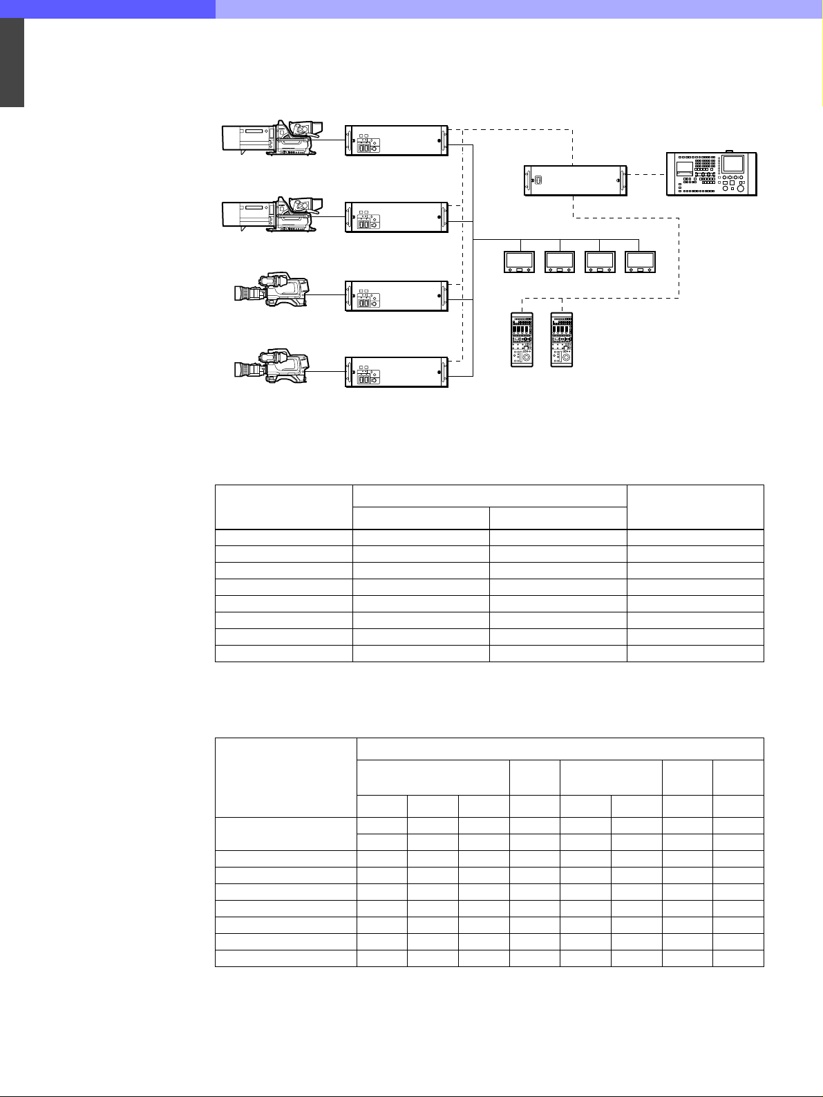
2
2-7-1-3 Progressive and Cinema Production System
HDC-900
HDC-900
HDC-950
HDC-950
HDCU-900
HKCU-901
HKCU-902
HKCU-903
HKCU-904
HDCU-900
HKCU-901
HKCU-902
HKCU-903
HKCU-904
HDCU-900
HKCU-901
HKCU-902
HKCU-903
HKCU-904
HDCU-900
HKCU-901
HKCU-902
HKCU-903
HKCU-904
PIX/WF or SDI Monitor
RCP-700/701
RCP-750/751
CNU-700
MSU-700A/750
Combination of boards
Combination of boards (S lots on the front)
System format
Second slot from the top Third slot from the top
Signal input/output slot
720/59.94P SDI RC/FC LC Third slot from the top
720/59.94P SDI Film Like FC LC Third slot from the top
1080/23.98PsF SDI RC/FC/LC/– RC/LC/– Top most slot
1080/24PsF SDI RC/FC/LC/– RC/LC/– Top most slot
*4
1080/25PsF SDI RC/FC/LC/– RC/LC/IF
1080/29.97PsF SDI RC/FC/LC/– RC/LC/IF
/– Top most slot
*4
/– Top most slot
1080/30PsF SDI RC/FC/LC/– RC/LC/– Top most slot
525/29.97PsF SDI RC LC/IF /– Second slot from the top
*4 When the IF-789A/789P board (HKCU-901) is going to be
installed, confirm beforehand that the RC-86 board is
installed in the second slot from the top.
Setting switches
Switch setting
System format
DPR-163 board
(S804 : LOCAL)
AT-141
board
FC-83 board
LC-41
board
RC-86
board
S805 S807 S806 S603 S2 S3 S2 S802
720/59.94P SDI
540P * * /1001 * * 720P *
NOT 60 Intr
720/59.94P SDI Film Like NOT 48 PsF /1001 * * 720P *
1080/23.98PsF SDI NOT 48 PsF /1001 ****
1080/24PsF SDI NOT 48 PsF /1000 ****
1080/25PsF SDI NOT 50 PsF /1000 ****
1080/29.97PsF SDI NOT 60 PsF /1001 ****
1080/30PsF SDI NOT 60 PsF /1000 ****
525/29.97PsF SDI NOT 60 PsF /1001 * * * 525
* -NA
Chapter 2 Total System 30HDC-900/950/930 Series Product Information Manual
Page 31

2
L
Figure 2-7-1-7: Example of connection using HDCU-900 (7) – System format: 720/59.94P SDI
Required boards
Slot to be installed
Board name
(Slots on the front)
Board name
(Slots on the rear)
Remarks
Top most slot DPR-163 SDI-54A HDCU-900
Second slot from the top RC-86 DIF-102 HDCU-900
Third slot from the top LC-41 SDI-54C HKCU-904
HDC-900
HDCU-900
123 4
SERIAL RET INPUT
123 4
1234 123
SERIAL RET INPUT
REFERENCE IN PROMPTER IN
SYNC OUT
PIX OUT WF OUT WF MODE
SYNC OUTSYNC OUT
1 2 3 MONI
SERIAL OUTPUT
1234
SERIAL OUTPUTSERIAL RET INPUT
SERIAL OUTPUT
SERIAL RET INPUT 1 to 4
REFERENCE IN
SYNC OUT
PROMPTER IN
SERIAL OUTPUT 1 to 3
HD-SDI RETURN VIDEO SIGNAL
REFERENCE SIGNAL
720/59.94P, tri-level SYNC SIGNAL
PROMPTER SIGNAL
HD-SDI SIGNAL
HDC-900
PIX 1
WF 1
HDCU-900
PIX 2
WF 2
123 4
SERIAL RET INPUT
123 4
1234 123
SERIAL RET INPUT
REFERENCE IN PROMPTER IN
SYNC OUT
PIX OUT WF OUT WF MODE
SYNC OUTSYNC OUT
1 2 3 MONI
SERIAL OUTPUT
1234
SERIAL OUTPUTSERIAL RET INPUT
SERIAL OUTPUT
Next HDCU-900
VCS-700
REMOTE
PIX A
WF A
SERIAL RET INPUT 1 to 4
SYNC OUT
SERIAL OUTPUT 1 to 3
CNU-700
HD-SDI RETURN VIDEO SIGNAL
720/59.94P, tri-level SYNC SIGNA
HD-SDI SIGNAL
SD REFERENCE SIGNAL
SD ANALOG VIDEO SIGNAL
VCS
Terminated at 75 Ω
Chapter 2 Total System 31HDC-900/950/930 Series Product Information Manual
Page 32

2
2-7-1-4 HD/SD Simul-Cast System
HDC-900
HDC-900
HDC-950
HDC-950
HDCU-900
HKCU-901
HKCU-904
HDCU-900
HKCU-901
HKCU-904
HDCU-900
HKCU-901
HKCU-904
HDCU-900
HKCU-901
HKCU-904
PIX/WF
(HKCU-901)
PIX/WF (HDCU-900)
HD-SDI Monitor
VCS-700
CNU-700
MSU-700A/750
RCP-700/701
RCP-750/751
Combination of boards
System format
HD SD
1080/59.94I SDI 525/59.94I SDI RC LC/IF/– Top most slot or second slot from the top
1080/59.94I SDI NTSC RC IF Top most slot or third slot from the top
1080/50I SDI
1080/50I SDI PAL RC IF Top most slot or third slot from the top
720/59.94I SDI 525/59.94I SDI RC LC
Setting switches
HD SD S805 S807 S806 S603 S 2 S802
1080/59.94I SDI 525/59.94I SDI NOT 60 Intr /1001 * 525
1080/59.94I SDI NTSC NOT 60 Intr /1001 * 525
1080/50I SDI 625/50I SDI NOT 50 Intr /1000 * 625
1080/50I SDI PAL NOT 50 Intr /1000 * 625
720/59.94I SDI 525/59.94I SDI
* -NA
625/50I SDI
System format
Combination of boards
(Slots on the front)
Second slot
from the top
RC LC/IF/– Top most slot or second slot from the top
Third slot
from the top
DPR-163 board
(S804 : LOCAL)
540P * *
NOT 60 Intr
Signal input/output slot
Second slot from the top or third slot
from the top
Switch setting
AT-141
board
/1001 720P 525
MSU-700A/750
LC-41
board
RC-86
board
Chapter 2 Total System 32HDC-900/950/930 Series Product Information Manual
Page 33

2
Figure 2-7-1-8: Example of connection using HDCU-900 (8) – System format: HD: 1080/59.94I SDI, SD: NTSC
Required boards
Slot to be installed
Board name
(Slots on the front)
Board name
(Slots on the rear)
Remarks
Top most slot DPR-163 SDI-54A HDCU-900
Second slot from the top RC-86 DIF-102 HDCU-900
Third slot from the top IF-789A VDA-57 HKCU-901
HDC-900
HDCU-900
WF OUT (For MSU)
PIX OUT (For MSU)
123 4
SERIAL RET INPUT
123 4
123 4
REFERENCE IN PROMPTER IN
SYNC OUT
PIX OUT WF OUT WF MODE
WF OUTPIX OUT
SYNC OUT
RET INPUT 1 to 4
SERIAL RET INPUT 1 to 4
SD SYNC OUT
REFRENCE IN
PIX OUT (For RCP)
PROMPTER IN
WF OUT (For RCP)
WF MODE (For RCP)
SERIAL OUTPUT 1 to 3
1 2 3 MONI
SERIAL OUTPUT
1234
SERIAL OUTPUTSERIAL RET INPUT
R-Y/RB-Y/BY/G 1 2
VBS OUTOUTPUTRET INPUT
VBS OUT
RGB/Component OUT
ANALOG RETURN VIDEO SIGNAL
HD-SDI RETURN VIDEO SIGNAL
SD SYNC REFERENCE SIGNAL
REFERENCE SIGNAL
PICTURE MONITOR OUTPUT FOR RCP
PROMPTER SIGNAL
WAVEFORM MONITOR OUTPUT FOR RCP
WAVEFORM MONITOR MODE FOR RCP
HD-SDI SIGNAL
ANALOG COMPOSITE VIDEO SIGNAL
ANALOG COMPONENT VIDEO SIGNAL
PIX 1
WF 1
HDC-900
HDCU-900
PIX 2
WF 2
123 4
SERIAL RET INPUT
123 4
123 4
PIX OUT (For MSU)
WF OUT (For MSU)
VCS-700
SYNC OUT
SYNC OUT
PIX A
WF A
REFERENCE IN PROMPTER IN
PIX OUT WF OUT WF MODE
WF OUTPIX OUT
Next HDCU-900
REMOTE
RET INPUT 1 to 4
SERIAL RET INPUT 1 to 4
PIX OUT (For RCP)
WF OUT (For RCP)
WF MODE (For RCP)
SERIAL OUTPUT 1 to 3
1 2 3 MONI
SERIAL OUTPUT
1234
SERIAL OUTPUTSERIAL RET INPUT
R-Y/RB-Y/BY/G 1 2
VBS OUTOUTPUTRET INPUT
RGB/Component OUT
SD SYNC OUT
VBS OUT
CNU-700
ANALOG RETURN VIDEO SIGNAL
HD-SDI RETURN VIDEO SIGNAL
PICTURE MONITOR OUTPUT FOR RCP
WAVEFORM MONITOR OUTPUT FOR RCP
WAVEFORM MONITOR MODE FOR RCP
HD-SDI SIGNAL
ANALOG COMPOSITE VIDEO SIGNAL
ANALOG COMPONENT VIDEO SIGNAL
SD SYNC REFERENCE SIGNAL
SD ANALOG VIDEO SIGNAL
VCS
Terminated at 75 Ω
SD REFERENCE SIGNAL
Chapter 2 Total System 33HDC-900/950/930 Series Product Information Manual
Page 34

2
2-7-2 Setting the System Format using
HDCU-950
For a system using the HDCU-950, the output signal
format must be set.
Normally the Multi-Format is set from the RM/MSU or a
device that is connected externally. However, it can
also be set by the switches on the AT-149 board or FC88 (HKCU-953) board.
(1) Setting the HD-SDI output
Set the output signal format as the HD-SDI signal. At
the same time, this setting becomes the shooting
mode of the camera.
1. Set the field frequency coefficient.
Setup switch : S420 on the AT-149 board (Factory
setting : REMOTE)
1.001 : Set the field frequency to 1/1.001 times
(Set the field frequency to 1.001 when
using NTSC (525/60) signal in the SD
system.)
1.000 : Set the field frequency to 1 time. (Set the
field frequency to 1.000 when using PAL
(625/50) signal in the SD system.)
REMOTE : Set it with RM/MSU, etc., that is
connected outside.
2. Set the field frequency.
Setup switch: S418 on the AT-149 board (Factory
setting: 60 V)
60 V : When the FC-88 board (HKCU-953) is not
used but the NTSC (525/60) signal is used in
the SD system.
50 V : When the FC-88 board (HKCU-953) is not
used but the PAL (625/50) signal is used in
the SD system.
48 V : At present, this function is not supported.
3. Set the shooting mode of the camera.
Setup switch : S419 on the AT-149 board (Factory
setting : INTR)
INTR : When shooting with interlacing system.
PROG : When shooting with progressive (PsF)
system.
540P : When shooting with 540-60P system. (At
present, this function is not supported.)
(3) Setting the frame conversion (when the HKCU-
953 is installed)
When the shooting mode of the camera is set to 24PsF,
set the HD-SDI output signal format from the HKCU-
953.
Setup switch : S2 on the FC-88 board (Factory
setting: OFF)
ON : When the shooting mode of the camera is set
to 24PsF, the frame frequency conversion is
implemented.
OFF :The frame frequency is not converted. The
same signal as the main HD-SDI signal is
output.
Note:
The setting of the frame conversion frequency must
follow the set format of the SD signal output.
When S423-1 on the AT-149 board is set to OFF
(NTSC), the frame frequency is converted to 60i (30
Hz).
When S423-1 on the AT-149 board is set to ON (PAL),
the frame frequency is converted to 50i (25 Hz).
Note:
If you select a format of 48i (48 field interlace) or
another format that is not supported by the HDCU-950,
the setting causes an error and the indicators (D201 to
D205) on the AT-149 board will flash.
(2)Setting the SD s i gnal output
When S420 on the AT-149 board is set to a position
other than REMOTE, set the SD signal output to NTSC
(525/60) or PAL (625/50).
Setup switch : S423-1 on the AT-149 board (Factory
setting : OFF)
ON : PAL (625/50)
OFF : NTSC (525/60)
Chapter 2 Total System 34HDC-900/950/930 Series Product Information Manual
Page 35

2
+B M3+B M3+B M3
+B M3+B M3+B M3
+B M3+B M3+B M3
+B M3+B M3+B M3
2-7-2-1 Standard System
HDC-950 + CA-905L
HDC-950 + CA-905L
HDC-950
HDC-950
HDCU-950
HKCU-951
HKCU-953
HDCU-950
HKCU-951
HKCU-953
HDCU-950
HKCU-951
HKCU-953
HDCU-950
HKCU-951
HKCU-953
PIX/WF
(HDCU-950)
PIX/WF (HDCU-950)
HD-SDI Monitor
VCS-700
MSU-700A/750
CNU-700
Combination of boards
Board name Slot 1 Slot 2 Slot 3 Slot 4 Slot 5 Slot 6
HDCU-950
HDCU-950 w/ HKCU-951
installed
HDCU-950 w/ HKCU-953
installed
RCP-700/701
RCP-720/721
RCP-730/731
RCP-740/741
RCP-750/751
MSU-700A/750
Front side AT-149 AVP-4 DTX-1 DRX-1 RC-91 -
Rear side CN-2219 CN-2220 SDI-70 HIF-5 DIF-124 -
Front side AT-149 AVP-4 DTX-1 DRX-1 RC-91 EN-145
Rear side CN-2219 CN-2220 SDI-70 HIF-5 DIF-124 VDA-61
Front side AT-149 AVP-4 DTX-1 DRX-1 FC-88 RC-91
Rear side CN-2219 CN-2220 SDI-70 HIF-5 SDI-73 DIF-124
Chapter 2 Total System 35HDC-900/950/930 Series Product Information Manual
Page 36

2
+B M3
+B M3
+B M3
+B M3
+B M3
2.62.62.6
2.62.62.6
2.62.6 2.62.6
1
8
9
15
1
13
14
25
4
+B M3
+B M3
+B M3
+B M3
+B M3
+B M3
+B M3
+B M3
+B M3
+B M3
+B M3
+B M3
+B M3
+B M3
+B M3 +B M3
+B M3
M3 M3
+B M3
+B M3
+B M3
+B M3
+B M3
2.62.62.6
2.62.62.6
2.62.6 2.62.6
1
8
9
15
1
13
14
25
4
+B M3
+B M3
+B M3
+B M3
+B M3
+B M3
+B M3
+B M3
+B M3
+B M3
+B M3
+B M3
+B M3
+B M3
+B M3 +B M3
+B M3
M3 M3
2-7-2-2 Standard HD/SD System
Figure 2-7-2-1 Example of connection using HDCU-950 (1) - System format: HD/SD system
HD REFERENCE SIGNAL
PROMPTER SIGNAL
HD-SDI RETURN VIDEO SIGNAL
REFERENCE SIGNAL
SD ANALOG Monitor
Waveform Monitor
HD-SDI Monitor
HD REFERENCE SIGNAL
HD-SDI RETURN VIDEO SIGNAL
HD-SDI SIGNAL
HD-SDI SIGNAL
SYNC OUT (HD)
PROMPTER IN
SERIAL RET INPUT 1 to 3
REFERENCE IN
SERIAL OUTPUT 1, 2
HDCU-950
SYNC OUT (HD)
SERIAL RET INPUT 1 to 3
SERIAL OUTPUT 1, 2
RC
SD SDI
OUT 1
SD SDI
OUT 2
PIX
OUT
WF
OUT
INCOM/TALLY/PGM
REFERENCE PROMPTER
SERIAL
RET1
OUT 1
SERIAL
OUT 2
MONI
RET2
RET3
SYNC OUT
RCP/CNU
MIC REMOTE
HDC-950 + CA-905L
MIC1
MIC2
WF MODE
HDC-950 + CA-905L
CAMERA
SD ANALOG Monitor
Waveform Monitor
HD-SDI Monitor
SD ANALOG VIDEO SIGNAL
SD REFERENCE SIGNAL
CNU-700
REFERENCE PROMPTER
RC
SD SDI
OUT 1
SD SDI
SERIAL
OUT 1
SERIAL
OUT 2
MONI
Ω
RET1
RET2
RET3
SYNC OUT
MIC REMOTE
Next HDCU-950
OUT 2
PIX
OUT
WF
OUT
INCOM/TALLY/PGM
HDCU-950
Terminated at 75
RCP/CNU
MIC1
MIC2
WF MODE
CAMERA
Chapter 2 Total System 36HDC-900/950/930 Series Product Information Manual
Page 37

2
+B M3
+B M3
+B M3
+B M3
+B M3
2.62.62.6
2.62.62.6
1
8
9
15
1
13
14
25
4
+B M3
+B M3
+B M3
+B M3
+B M3
+B M3
+B M3
+B M3
+B M3
+B M3
+B M3
+B M3
+B M3
+B M3
+B M3
2.62.6 2.62.6
2.62.6 2.62.6
+B M3
+B M3
M3 M3
+B M3
+B M3
+B M3
+B M3
+B M3
2.62.62.6
2.62.62.6
1
8
9
15
1
13
14
25
4
+B M3
+B M3
+B M3
+B M3
+B M3
+B M3
+B M3
+B M3
+B M3
+B M3
+B M3
+B M3
+B M3
+B M3
+B M3
2.62.6 2.62.6
2.62.6 2.62.6
+B M3
+B M3
M3 M3
2-7-2-3 HD/SD Film Like System
Figure 2-7-2-2 Example of connection using HDCU-950 (2) - System format: HD/SD film like system
SYNC SIGNAL
PROMPTER SIGNAL
SDI RETURN VIDEO SIGNAL
REFERENCE SIGNAL
HD-SDI SIGNAL
HD-SDI SIGNAL
SUB REFERENCE SIGNAL
SD-SDI SIGNAL
Picture Monitor
Waveform Monitor
SYNC SIGNAL
SDI RETURN VIDEO SIGNAL
HD-SDI SIGNAL
HD-SDI SIGNAL
SD-SDI SIGNAL
SYNC OUT
PROMPTER IN
SERIAL RET INPUT 1 to 3
REFERENCE IN
SERIAL
OUTPUT 1, 2
HD SDI OUT 1, 2
HDC-950 + CA-905L
FRAME REF IN
REFERENCE PROMPTER
FC
RC
HD SDI
SD SDI
OUT 1
OUT 1
HD SDI
SD SDI
OUT 2
SERIAL
OUT 1
RET1
OUT 2
SYNC OUT
PIX
REF IN
OUT
WF
OUT
OUT
HDCU-950
SYNC OUT
SERIAL RET INPUT
1 to 3
SERIAL
OUTPUT 1, 2
INCOM/TALLY/PGM
OUT 2
MONI
RET2
RET3
MIC REMOTE
SERIAL
FRAME
HD SDI OUT 1, 2
REFERENCE PROMPTER
FC
RC
HD SDI
SD SDI
OUT 1
OUT 1
RCP/CNU
MIC1
MIC2
WF MODE
HDC-950 + CA-905L
MIC1
CAMERA
CAMERA
Picture Monitor
Waveform Monitor
SD ANALOG VIDEO SIGNAL
SD REFERENCE SIGNAL
CNU-700
HD SDI
SD SDI
OUT 2
PIX
OUT
WF
OUT
HDCU-950
Terminated at 75
OUT 2
FRAME
REF IN
OUT
INCOM/TALLY/PGM
Ω
SERIAL
OUT 1
SERIAL
OUT 2
MONI
RET1
RET2
RET3
RCP/CNU
MIC2
WF MODE
SYNC OUT
MIC REMOTE
Next HDCU-950
Chapter 2 Total System 37HDC-900/950/930 Series Product Information Manual
Page 38

2
+B M3
+B M3
+B M3
+B M3
+B M3
2.62.62.6
2.62.62.6
2.62.6 2.62.6
1
8
9
15
1
13
14
25
4
+B M3
+B M3
+B M3
+B M3
+B M3
+B M3
+B M3
+B M3
+B M3
+B M3
+B M3
+B M3
+B M3
+B M3
+B M3 +B M3
+B M3
2.6 2.62.6 2.6
+B M3
+B M3
M3 M3
+B M3
+B M3
+B M3
+B M3
+B M3
2.62.62.6
2.62.62.6
2.62.6 2.62.6
1
8
9
15
1
13
14
25
4
+B M3
+B M3
+B M3
+B M3
+B M3
+B M3
+B M3
+B M3
+B M3
+B M3
+B M3
+B M3
+B M3
+B M3
+B M3 +B M3
+B M3
2.6 2.62.6 2.6
+B M3
+B M3
M3 M3
2-7-2-4 Analog NTSC/PAL System
Figure 2-7-2-3 Example of connection using HDCU-950 (3) - System format: Analog NTSC/PAL system
SD SYNC REFERENCE SIGNAL
PROMPTER SIGNAL
ANALOG RETURN VIDEO SIGNAL
REFERENCE SIGNAL
ANALOG COMPONENT VIDEO SIGNAL
ANALOG COMPOSITE VIDEO SIGNAL
SD SYNC REFERENCE SIGNAL
ANALOG RETURN VIDEO SIGNAL
ANALOG COMPONENT VIDEO SIGNAL
ANALOG COMPOSITE VIDEO SIGNAL
SYNC OUT
PROMPTER IN
RET INPUT 1 to 3
REFERENCE IN
RGB/
Component OUT
VBS OUT
SYNC OUT
RET INPUT 1 to 3
RGB/
Component OUT
VBS OUT
RC
EN
VBS
OUT
Y/G
B-Y/B
R-Y/R
HDCU-950
RC
EN
VBS
OUT
Y/G
B-Y/B
R-Y/R
SD SDI
OUT 1
SD SDI
OUT 2
PIX
OUT
WF
OUT
INCOM/TALLY/PGM
SD SDI
OUT 1
SD SDI
OUT 2
PIX
OUT
WF
OUT
INCOM/TALLY/PGM
REFERENCE PROMPTER
SERIAL
RET1
OUT 1
SERIAL
OUT 2
MONI
REFERENCE PROMPTER
SERIAL
OUT 1
SERIAL
OUT 2
MONI
SYNC OUT
RET2
RET3
RCP/CNU
MIC REMOTE
RET1
SYNC OUT
RET2
RET3
RCP/CNU
MIC REMOTE
HDC-950 + CA-905L
MIC1
MIC2
WF MODE
HDC-950 + CA-905L
MIC1
MIC2
WF MODE
CAMERA
CAMERA
PIX 1
WF 1
HDCU-950
WF 2
PIX 2
SD ANALOG VIDEO SIGNAL
Next HDCU-950
SD REFERENCE SIGNAL
VCS-700
PIX A
WF A
REMOTE
VCS
CNU-700
Terminated at 75
Ω
Chapter 2 Total System 38HDC-900/950/930 Series Product Information Manual
Page 39

2
2-8. Rack Mounting of System Equipment
19-inch size equipment
The HDCU-900 Camera Control Unit, CNU-700 and
CNU-500 Camera Command Network Units, and VCS700 Video Selector can be mounted in a 19-inch
standard EIA rack. These units either mount directly
into the rack or with optional slide rails such as the
Sony RMM-30 Rack Mount Rail. These slide rails allow
the unit to be easily pulled out from the rack and are
recommended if you intended to pull out the unit
frequently.
Warning for Safety Purpose: It takes two or more people to
mount a unit into a rack. Mounting the unit into a rack by
yourself can cause back or other injuries.
Mounting the unit direct ly to the rack
Fix the unit to the rack using the rack mount bracket of
the unit. Daily maintenance is easy with the unit
mounted with this method.
Universal-type rack
12.7
15.9
15.9
12.7
Wide-type rack
12.7
31.75
12.7
2. Secure the inner members to both sides of the unit
with the screws (+B4 x 8). Use the screws removed
from or supplied with the unit.
3. Loosen the screw of the bracket of the outer
member.
4. Attach the front and rear brackets of the outer
member to the rack. Screws (b), (c) and (d) are
supplied with the RMM-30.
c
Rear
12.7
15.9
15.9
12.7
15.9
15.9
Plate nut
Front
Mounting the unit using the RMM-30 Rack Mount
Rail
When the RMM-30 Rack Mount Rail is used, the unit
can be mounted into a rack with a depth of 660 to 830
mm (26 to 32 3/4 inches). Proceed as follows:
1. Pull out inner member while pushing against the
stopper.
Stopper
Inner member
Outer member
b
Screw
12.7
31.75
12.7
31.75
Screw
Front
31.75
d
31.75
Screw
Screw
When a 1U unit is mounted
(1) Attach the front bracket to the inside of the front
of the rack at the screw holes at 15.9 mm (22/
32 inch) intervals, using screw (b) and plate nut
(c).
(2) Attach the rear bracket to the outside of the rear
of the rack at the screw holes at 31.75 mm (1 5/
16 inches) intervals, using screws (d).
When a unit other than 1U height is mounted
(1) Attach the front bracket to the outside of the
front of the rack at the screw holes at 31.75 mm
intervals, using screws (d).
d
Rear
d
Chapter 2 Total System 39HDC-900/950/930 Series Product Information Manual
Page 40

2
(2) Attach the rear bracket to the outside of the rear
of the rack at the screw holes at 31.75 mm
intervals, using screws (d).
5. Fasten the screws loosened in step 3.
6. Pull the rails out.
7. Insert the inner member to the outer member while
pushing against the stopper, and then fully push
the unit into the rack.
Warning for Safety Purpose: It takes two or more people
to mount a unit into a rack. Mounting the unit into a rack by
yourself can cause back or other injuries.
Installation
1. Secure the RMM-301 in the 19-inch EIA standard
rack with the four B5 screws (6 mm or longer).
57.2 mm
B5 screw
(6 mm or longer)
RMM-301
B5 screw
(6 mm or longer)
2. Secure the unit with the supplied four screws (B4 x
6) and the four washers.
8. Push the unit into the rack, and secure the front
panel to the rack with screws (+RK M5 x 16 to 20)
and washers (φ 5).
HDCU-950
The two HDCU-950 can be mounted in parallel in a 19inch EIA standard rack by using the rack mount
adapter RMM-301 (optional). (Three-unit height)
W4
x 6
B4
Warning
• If the rack falls due to the weight of the equipment, it
may cause death or major injury. To prevent the rack
from falling or moving, be sure to fix the rack to the
floor.
• If the rack falls, death or serious injury may result.
When attaching the unit, be sure to fix the rack to the
floor and be careful not to attach at a height of 1.2 m
or higher from the floor.
Caution
• Use the specified rack mount adapter. If not, injury
could occur by drop of the unit because strength of
the shelf board is not enough.
• Mount the unit with more than two persons. A one-
man job may cause injury.
• Be careful not to catch your finger or hand in the rack
mount rail.
• Mount in the rack in a stable position. Injury could
occur by drop of the unit in unbalance condition of
W4
B4 x 6
Chapter 2 Total System 40HDC-900/950/930 Series Product Information Manual
Page 41

2
installation or removal. Install in a posture of stability
and carefully.
Required Parts
• Rack mount adapter RMM-301 1 set
• Screw (B4 x 6) (supplied with the RMM-301) 4 pcs
Sony part No.: 7-682-560-04
• Washer (W4, SMALL) (supplied with the RMM-301) 4
pcs
Sony part No.: 7-688-004-03
• B5 screw (6 mm or longer) 4 pcs
RCP-700 Series and MSU-700 Series
The RCP-750/751/700/701 and the MSU-700A/750
can be mounted into a 19-inch rack using an optional
drawer. Each type of equipment requires different
parts to mount it into the drawer.
Cover
2
RCP-700 Series
Drawer
Chapter 2 Total System 41HDC-900/950/930 Series Product Information Manual
Page 42

Chapter 3 Benefit of Sony ADSP (Advanced Digital Signal Processing)
3
Benefit of Sony ADSP (Advanced
Digital Signal Processing)
Page 43

3
3-1. Full DSP Camera Processing
The HDC-900 Series uses 12-bit A/D conversion
based on the latest LSI technology. This advanced
technology has allowed Sony to take a major step
forward from the 10-bit conversion of its previous
generation of cameras - a move that was not possible
with earlier A/D converters and DSP LSIs.
(1) Multi Matrix
Multi Matrix is a function that electronically adjusts the
basic RGB color 'taking characteristics' of the camera
to achieve optimum colorimetry. It makes it easy to
match the color of cameras under multi-camera
operations, or to reproduce the characteristics of
another type of camera. It can also be used to
manipulate color for a particular special effect. A
conventional linear matrix function provides only six
adjustable parameters, with considerable interaction
between their effects on a specific color. Multi Matrix
divides the spectrum into 16 segments, each of 22.5
degrees, for each of which there is an independent
hue and saturation parameter. Multi Matrix allows the
selection of each of these segments, with separate
adjustment of hue and saturation parameters.
Operation flow is as follows:
1. Select Multi Matrix on the paint menu of the MSU-
700A/750 Master Set-up Unit.
2. Turn the Matrix and the Multi switches to ON.
3. The MSU-700A/750 EL display now shows a
representation of the Multi Matrix as it would appear
on a vectorscope. You can select the desired color
phase that you want to adjust.
4. After selection of the color phase, its hue and
saturation can be adjusted.
Photo 3-1: Multi Matrix ON and OFF
Normal
On
Photo 3-2: Multi Matrix (Vectorscope)
Figure 3-1: Multi Matrix
R-Y
hue
saturation
B-Y
Normal
ON
Chapter 3 Benefit of Sony ADSP (Advanced Digital Signal Processing) 43HDC-900/950/930 Series Product Information Manual
Page 44

3
(2) Auto Knee
When the Auto Knee button on the MSU or RCP panel
is pressed, it optimizes the knee point and knee slope
Figure 3-2: Auto Knee curve image
Input signal level
white clip
auto slope
for best reproduction of the high lights. The Adaptive
Highlight control function can also be used in
conjunction with Auto Knee.
point limit
auto knee circuit
(3) Gamma
New 12-bit A/D conversion more precisely defines the
required gamma characteristic by using a gamma
curve created from 48 segments. This is in comparison
with the 32 segments in the previous camera range.
(4) Black Gamma
Black Gamma allows control of the linear part of the
gamma characteristic, providing adjustment of the
shadow areas of the picture during shooting.
Also, the Black Gamma range can be adjusted
depending upon the situation.
(5) Black Clip
Improvements in the Black Clip circuitry have
improved the signal/noise ratio for more natural
reproduction.
(6) Auto Black/White
The HDC-900 Series provides superb accuracy in
black and white balance.
3-2. Precise Handling of Highlight Position
(1) Optimized bit assignment
Highlights are compressed by a pre-knee circuit
before A/D conversion, providing the most efficient
utilization of the 12-bit A/D conversion process.
(2) Knee saturation
Knee Saturation eliminates both the 'washed out' effect
and hue changes in overexposed areas of a picture,
providing more natural color reproduction.
Photo 3-3: Knee saturation ON and OFF
Output signal level
Washed out
Normal
On
Chapter 3 Benefit of Sony ADSP (Advanced Digital Signal Processing) 44HDC-900/950/930 Series Product Information Manual
Page 45

3
(3) Low key saturation
With conventional cameras, low light areas can be
subject to a reduction in saturation. This can result in
color in these areas being "washed out". The Low Key
Saturation function on the HDC-900 Series eliminates
this problem by optimizing the amplification of color
saturation at low light levels, providing more natural
color reproduction.
Photo 3-4: Low key saturation ON and OFF
Normal
On
(4)Adaptive highlight control (Auto Knee mode )
Conventional cameras only have a single knee point/
slope characteristic. In contrast, the Sony ADSP
system has multiple knee point/slope characteristics.
The camera monitors the brightness of all areas of the
picture and adapts the knee point/slope for optimum
reproduction. A typical example is shooting an interior
scene which includes a sunlit exterior seen through a
window. This new function applies only to video levels
in excess of the knee point, the middle and low
luminance parts remaining unchanged.
Colorimetry in dark areas are improved.
Photo 3-5: Adaptive highlight control ON and OFF
Normal (Olympic Stadium of Barcelona)
On (Olympic Stadium of Barcelona)
(5) Triple Skin Tone Detail Correction
Skin Tone Detail Correction controls the detail level of
those objects which have specific color tones. The
HDC-900 Series allows detail to be set independently
for each of three separate color ranges. Colors are not
limited to skin tones, but can be set for any color. Detail
may be increased or decreased relative to the normal
level.
Phase: Sets the color phase for which Skin Tone
Width: Sets the color width for which Skin Tone
Saturation:Sets the saturation for which Skin Tone
Figure 3-4: Skin Tone Detail Correction
Detail Correction is activated.
Detail Correction is activated.
Detail Correction is activated.
Width
R-Y
Phase
Figure 3-3: Knee curve image
Intput signal level
white clip
auto slope
knee point 0
knee point 1
knee point 2
........
knee point 3
B-Y
Saturation
Output signal level
knee point n
Chapter 3 Benefit of Sony ADSP (Advanced Digital Signal Processing) 45HDC-900/950/930 Series Product Information Manual
Page 46

3
Photo 3-6: Triple Skin Tone Detail Correction ON and OFF
Normal
CH-1 On
(6)Adaptive Detail Control
The Adaptive Detail Control provides natural detail
enhancement on extreme highlights by automatically
Photo 3-7: Adaptive Detail Control ON and OFF
Softer
CH-2 On
altering the amplitude of the edge signal for those
forms of high contrast signals.
Sharper Softer
Normal
On
The black edges are removed.
Chapter 3 Benefit of Sony ADSP (Advanced Digital Signal Processing) 46HDC-900/950/930 Series Product Information Manual
Page 47

3
(7)Electronic Soft Focus
This function is similar to an optical soft filter. By
subtracting the edge enhancement signal from the
original video signal, slight 'defocused' pictures are
created electronically. This is an important new
creative feature that can be used to either complement
or replace the Skin Tone Detail Correction function,
when more of a 'film look' is sought for close-ups, etc.
Figure 3-5: Electronic Soft Focus signal image
Original
Enhancer
Soft Focus
Photo 3-8: Electronic Soft Focus ON and OFF
Normal
Electronic Soft Focus On (Softer than with Detail Off)
Detail Off
Chapter 3 Benefit of Sony ADSP (Advanced Digital Signal Processing) 47HDC-900/950/930 Series Product Information Manual
Page 48

3
3-3. Outstanding reliability and easy maintenance
One of the most important concerns for broadcasters
is the reliability of equipment. This is considerably
improved with Sony digital processing. In Sony ADSP
cameras, all the processing parameters are
completely and precisely defined at the design stage,
and almost all the potentiometers are replaced by
semiconductor memories. Consequently, Sony ADSP
cameras show extremely stable performance,
regardless of environmental conditions such as
temperature, humidity, shock and vibration. This high
stability, together with the advantages of the self-
3-4. Low power consumption
To achieve its design aim of complete digital
processing, including digital implementation of the
nonlinear processing stages, Sony has developed
VLSIs which contain over 1,600,000 actual gates. This
complexity demonstrates the advances that Sony has
made in the application of its semiconductor
technology. Despite this complexity, Sony ADSP
cameras approach the same low power consumption
as previous analog/digital portable cameras. This has
been made possible by using the Sony EDA
(Electronic Design Automation) system to optimize the
complex camera circuitry in a short time scale and to
incorporate the latest LSI technologies (2.5 V drive and
0.35 µm design rule) to give a total power consumption
of just 25 W for the HDC-950 portable HD camera (in
stand-alone use without options).
contained menu system, enables easy and accurate
set-up of camera systems for regular realignment.
Finally, a great benefit of Sony ADSP cameras is their
advanced self-diagnostic system. HDC-900 Series
cameras detect problems in their digital processing
and provide a viewfinder warning indication. Detailed
information, such as identifying the faulty board, is also
shown on the Master Set-up Unit screen and the
Camera Command Network Unit character display to
provide easy and rapid fault location.
Chapter 3 Benefit of Sony ADSP (Advanced Digital Signal Processing) 48HDC-900/950/930 Series Product Information Manual
Page 49

Chapter 4 Control Syste
m
4
Control System
Page 50

4
4-1. Sony Camera Command Network System
Several decades of TV operations have led to the
development of many alternative operational and
engineering philosophies relating to the deployment of
video and technical control and to the monitoring and
routine maintenance of multi-camera studio and OB
truck installations. Sony has re-examined the entire
studio camera architecture with the goal of structuring
a far higher degree of system flexibility. This new
architecture is based on:
4-2. Master Set-up Unit – MSU-700A/750
The Master Set-up Unit (MSU) is the centralized
technical control position for multi-camera systems.
The MSU-700A/750 has been designed to provide
comprehensive and wide ranging technical
supervision and alignment of a complex camera
system from a single centralized panel. If it is desirable
in a large program origination complex to extend this
supervision to more than one control location (for
example, separate operational and engineering/
maintenance control centers) then a number of MSU700A/750 units can access the entire camera system.
To exercise maximum flexibility in controlling a multicamera system, the MSU-700A/750 is designed to
work in conjunction with the CNU-700 and CNU-500
Command Network Units. However, if a simplified
system is desired, the MSU-700A/750 can also
operate as a stand-alone unit. It provides rapid, fingertip access to all controls relating to the smooth
functioning of an operational system, including:
• Technical alignment controls for the entire camera
chain
• Picture and waveform monitor switching
• System configuration
• Control data filing
Extended Technical Access to Camera Video
Processing
A traditional high-end studio/OB camera chain entails
a multiplicity of technical adjustments. In combination
they optimize of the technical alignment of the RGB
video processing channels and allow a broad degree
of control over certain critical video subsystems (such
as image enhancement, color reproduction, dynamic
range, etc.). Typically, these technical controls are
segregated into those requiring regular operational
access - and are provided as remote adjustments on
video operational panels or technical control panels and others, perhaps requiring less frequent access,
which are relegated to screwdriver adjustments on
various circuit boards within the camera head and
HDCU. This separation often entailed a degree of
protracted (and frustrating) re-alignment when subtle
creative readjustments are desired for a particular
picture composition.
In the HDC-900 Series camera system, Sony has
adopted the philosophy that all technical controls are
important and that remote access to virtually all
controls on a single control panel would bring higher
operational efficiency. This led to the introduction of
the MSU-700A/750 Master Set-up Unit. To avoid undue
complication of the ergonomics of the panel layout that
would result from such extensive access, a novel
Electro Luminescent (EL) sub-panel forms an integral
part of the overall MSU-700A/750 control panel - Photo
4-1. This menu-driven touch screen allows remote preprogrammed and logical access to dozens of
technical adjustments. Perhaps no other system can
• High-speed communication of digital control
commands
• A considerably augmented Master Set-up Unit, the
MSU-700A/750
• The introduction of a powerful technical 'nerve
center' concept - the camera Command Network
Units, CNU-700 and CNU-500
• Electronically assignable camera remote control
panels for use with these camera command network
units
better illustrate the enhanced degree of centralized
control than that relating to access to the many
adjustments required for the image enhancement
system. Depending upon the creative desires of the
program director, the MSU-700A/750 allows highly
flexible, finger-tip access to all critical adjustments,
including skin detail control.
The main features of the MSU-700A/750 are given
below.
(1) Easy operation
• Frequently used functions are directly accessed from
the panel.
• The following modes can be easily accessed by
using the new EL touch panel display for
maintenance and daily operation.
• Paint mode: Various paint items such as White,
Black and Flare are adjustable
• File mo de : Storing, retrieving and transferring
reference files, lens files and scene files between
camera heads on a PC memory card
• Maintenance mode: System phase control, HDCU
video level alignment, selection of character display
from a CNU-700 and CNU-500, etc.
• Configuration mode: Entire control system
configuration, RCP assignment, etc.
• Card mode: PC memory card initialize, store to PC
memory card/recall from PC memory card, etc.
• Multi-mode: Setting of multi-camera operation such
as 'All', 'Control Priority', 'Parallel Mode', etc.
(2) Multi-MSU operation
In a conventional system, a single MSU controls a
single studio or multiple studios. However, in this new
control system, multiple MSUs can be used to remotely
control/supervise a single studio from different
operational engineering and control rooms.
(3) Standard switch
Users standard setting data is easily recalled by
pressing the 'standard' switch.
Photo 4-1: MSU-700A Master Set-up Unit
Chapter 4 Control System 50HDC-900/950/930 Series Product Information Manual
Page 51

4
4-3. Camera Command Network Units – CNU-700 and CNU-500
The CNU-700 and CNU-500 Camera Command
Network Units are designed as the technical 'nerve
center' of a Star Shape Network System where all
commands such as 'All', 'Control Priority', 'Parallel/
Mode', etc. are centralized and distributed to the
respective HDCUs of the studio system. They are
furnished with an RS-232C port to provide interface
capability to external systems such as ISR (Interactive
Status Reporting), external PC or modem and robotics
control systems. They can be mounted in a 19-inch
standard rack (3U height for the CNU-700, and 1U
height for the CNU-500). Through the modem or PC,
camera data files can be transferred from a master
camera in a studio to cameras at several remote sites
during a live broadcast.
By employing a RISC-based microprocessor in the
CNU-700 and CNU-500, the communication speed
has been greatly improved. Consequently, real-time
control and instant response to the MSU-700A/750 or
RCP-700 Series commands have been made possible.
With the combination of one VCS-700 Video Selector
with a CNU-700 or CNU-500, each of six pictures and
six waveform monitoring video signals can be handled
(and expanded to 96 of each with eight CNU-700
units).
Through a CNU-700 or CNU-500, one RCP can
control one HDCU while one MSU is able to control
multiple HDCUs. All units connected to the CNU can
easily communicate with each other. Because of this
useful new -function, simultaneous control of multi
cameras, file transfer between multi cameras and
control from an external device are now possible.
As a convenient tool for system set-up and
maintenance, both MSU control routing and CNU
control assignment can be displayed on a monitor.
Since the CNU is the nerve center of a system, it has
a bypass facility to maintain communication between
the HDCUs and RCPs in the event of a CNU
malfunction or power loss. Therefore, even when the
power unit or AT board of the CNU-700 or CNU-500
has failed, camera heads and HDCUs can be directly
controlled from the RCPs to let program production
continue.
As mentioned in Section 2, Total System, the cost
versus performance balance between the two types of
Camera Command Network Units allows users to build
up systems that meet their application needs. The
CNU-500 is suitable for applications with up to six
cameras, while the CNU-700 can be expanded to
handle up to 12 cameras with use of the BKP-7930
optional expansion board.
(1) High-speed data transmission rates
CNU to MSU/RCP/HDCU: More than 500 Kbps
Camera Head to HDCU: 35 Kbps
(2) System configuration
Basic system: Up to six cameras with one CNU-700
or CNU-500
Expanded system: Up to 12 cameras with one CNU-
700 with one BKP-7930 optional board installed
Maximum system: Up to 96 cameras with eight CNU-
700 units (each with a BKP-7930 optional board
installed) via I/O port on the rear panel (four MSU-
700A/750 Master Set-up Units required).
(3) Character display
Information concerning the camera heads and HDCUs
connected to the CNU-700 and CNU-500 can be
displayed on a monitor via the CHARACTER
connector. This includes:
• Camera settings
• System connection information
• Results of Auto set-up
• Self-diagnostics information
(4) Emergency feature
In the event of a problem with the CNU-700 and CNU500, turning their internal OPERATION switch to the
EMERGENCY position allows control signals from the
remote control panel to be directly connected to the
camera head. In this way, program production
cancontinue by bypassing the CNU.
Table 4-1: A comparison between the CNU-700 and CNU-500
CNU-700 CNU-500
Up to 6 cameras Up to 6 cameras
Number of Cameras
connectable
Number of RCPs connectable
Multi MSU connectable Yes No
Multi VCS connectable Yes No
Other controller connectable Yes Available with optional AUX connector
Programable with remote
control
RS-232C connector for ISR Yes Yes
RS-232C connector for
switcher etc.
REF. video in Yes Yes
Character out 2 1
Assignment between RCP and
CHU/CCU
Up to 12 cameras with BKP-7930 fitted No
Up to 96 cameras with multi CNU
connected
Up to 6 RCPs Up to 6 RCPs
Up to 12 RCPs with BKP-7930 fitted No
Up to 96 RCPs with multi CNU
connected
Yes N o
One No
Two when BKP-7930 fitted No
Free Fixed
No
No
Chapter 4 Control System 51HDC-900/950/930 Series Product Information Manual
Page 52

4
CNU-700 CNU-500
Power supply to RCP Yes
No (But RCP can be powered from
CCU)
Height 3 U 1 U
19-inch standard rack
mauntable
Yes Yes
Figure 4-1: CNU-700/500 Basic System Configurations (Up to six cameras with one CNU-700 or CNU-500)
Command
Video
Character
HDC-900
1
2
3
HDC-950
4
5
6
HDCU-900
Down Con.Outputs
CNU-700/500
HDCU-950
Monitor
Waveform
Monitor
VCS-700
NTSC or
PAL
MSU-700A
Vector
Scope
B/W monitor
for character
display
RCP-700 Series
Chapter 4 Control System 52HDC-900/950/930 Series Product Information Manual
Page 53

4
Figure 4-2: CNU-700 Expanded System Configurations (Up to 12 cameras with one CNU-700 with one BKP-7930 installed)
Monitor
HDC-900
1
2
HDCU-900
Down Con.
Outputs
Waveform
Monitor
Vector
Scope
3
4
5
BKP-7930
6
HDC-950
7
8
9
10
11
12
HDCU-950
Down Con.Outputs
CNU-700
VCS-700 (2)VCS-700 (1)
NTSC
or
PAL
MSU-700A
B/W monitor
for character
display
Command
Video
Character
RCP-700 Series
Chapter 4 Control System 53HDC-900/950/930 Series Product Information Manual
Page 54

4
Figure 4-3: CNU-700 Maximum System Configurations (expandable to 96 cameras)
HDC-900
1
2
6
7
8
12
HDC-950
13
14
18
19
20
24
HDCU-900
HDCU-950
Down Con.
Outputs
Down Con.
Outputs
Down Con.
Outputs
Down Con.
Outputs
VCS-700 (3)
BKP-7930
CNU-700 (1)
CNU-700 (2)
BKP-7930
VCS-700 (2)VCS-700 (1)
NTSC or
MSU-700A
VCS-700 (4)
B/W monitor
for character
display
PAL
Command
Video
Character
Note:
With the addition of an external camera selector switching panel,
upto 96 cameras with 8 CNU-700s (with BKP-7930 installed) can
be controlled from a single MSU-700A.
Monitor Waveform
RCP-700 Series
RCP-700 Series
Monitor
Vector
Scope
Chapter 4 Control System 54HDC-900/950/930 Series Product Information Manual
Page 55

4
Figure 4-4: Multi-MSU Operation Example (1)
HDC-900
HDC-950
HDCU-900
HDCU-950
VCS-700
CNU-700 (1)
Down Con.
Outputs
ENGINEERING ROOM
MSU-700A
MSU-700A
RCP-700 Series
VIDEO CONTROL ROOM
Chapter 4 Control System 55HDC-900/950/930 Series Product Information Manual
Page 56

4
Figure 4-5: Multi-MSU Operation Example (2)
Supervising a complete system with a supervisiory MSU
STUDIO 1
HDC-900
HDCU-900 VCS-700
Down Con.
Outputs
MSU-700A
STUDIO 2
STUDIO 3
HDC-900
HDC-900
CNU-700
HDCU-900 VCS-700
Down Con.
Outputs
CNU-700
HDCU-900 VCS-700
Down Con.
Outputs
RCP
RCP
MSU-700A
MSU-700A
Supervisory MSU
CNU-700
MSU-700A
Chapter 4 Control System 56HDC-900/950/930 Series Product Information Manual
Page 57

4
4-4. New Remote Control Panels - RCP-750/751
The RCP-750/751 Remote Control Panel is newly
designed for remote control of the Sony BVP/HDCSeries Color Video Camera via the CCU/HDCU-Series
Camera Control Unit. The panel is connected to the
CCU/HDCU-Series Camera Control Unit (or the CNUseries Camera Command Network Unit, which is
connected to the CCU/HDCU-Series) by a special
cable of up to 200 m (656 feet) in length.
The RCP-750 and RCP-751 are completely identical
in their functions except with respect to the iris and
master black adjustments, for which the RCP-750 uses
a joystick type control while the RCP-751 uses rotary
knobs.
The RCP-750/751 has the following features:
Optimal control -arrangement for basic camera
operation
This remote control panel is provided with essential
control functions for basic operation of a BVP/HDC
Series camera. The buttons, knobs, and other controls
have been arranged according to their functions and
with consideration to their frequency of use. Indicators
and buttons light or flash to indicate the status of the
system operation. Also, guard frames are provided to
protect against accidental use of those buttons vital to
camera operation. These features ensure easy and
error-free use of this remote control panel.
Controlling the automatic setup function
The RCP-750/751 has built-in microcomputers that
reliably perform automatic setup for the majority of the
control items. The various items can be automatically
adjusted independently or in combination.
Four units mountable on a 19- inc h rack
Up to four units of this control panel can be mounted in
a line on a 19-inch EIA standard rack.
Controlling the scene file function
Camera adjustment and control data such as paint
data for a particular scene can be stored in the video
camera in the form of a scene file. The stored data can
easily be retrieved at any time to automatically adjust
the camera to the shooting conditions for that
particular scene. This panel enables up to five scene
files to be created and handled.
Controlling the ECS/shu tter function of the camera
The ECS (Extended Clear Scan) and electronic shutter
functions of the camera can be turned on/off from this
panel. The ECS frequency and shutter speed are also
selectable.
Signal transmission via a digital line
Between this remote control panel and the camera
control unit, signals are digitally transmitted via a
single connection cable (CCA-5), ensuring a reliable
signal. Operating power is also supplied via the cable.
Memory Stick media card slot
Various data, including scene files and reference files,
can be stored on a Memory Stick media card and
reproduced at any time.
Touch panel with 31/2-inch LCD for various
operations
The control panel has a touch panel that permits
various items to be selected and adjusted on the LCD
in menu format.
Parallel operation with another control panel
Video cameras can be concurrently controlled from
this panel and another controller, such as the MSU700A/750A/750 Master Setup Unit.
Chapter 4 Control System 57HDC-900/950/930 Series Product Information Manual
Page 58

4
Figure 4-6: Operation Panel of the RCP-750/751
RCP-750
1Control select block q;Power and output signal select block
2STANDARD button
3Camera/CCU function
ON/OFF buttons
PARA
STANDARD
5600K
PAINT 1 PAINT 2
MASTER SLAVE
SKIN DTL
CHAR
AUTO HUE
ACTER
AUTO
KNEE
CAM PW
AUTO SETUP
START/
LEVEL
BREAK
SKIN
DTL
BLACK
DETAIL
GATE
GAMMA
PAINT 3 SCENE MAINTE
NANCE
TEST BARS CLOSE
WHITE BLACK
FUNCTION
qaAUTO SETUP block
qsMenu operation block
4WHITE knobs
5BLACK/FLARE knobs and
indicator
6Camera number/tally indication
window
7ALARM indicator
8CALL button
9PANEL ACTIVE button
RCP-751
6Camera number/tally indication
window
7ALARM indicator
8CALL button
9PANEL ACTIVE button
BLACK/FLARE
MASTER
BLACK
RELATIVE
ALARM CALL
PANE L
ACTIVE
REMOTE CONTROL PANEL
BLACK/FLARE
MASTER
BLACK
IRIS/MB
ACTIVE
ALARM CALL
PANE L
ACTIVE
REMOTE CONTROL PANEL
WHITE
RELATIVE
RELATIVE
IRIS/MB
ACTIVE
AUTO
AUTO
qfDETAIL knob
DETAIL
a
EXT
IRIS
a
EXT
SENS
CLOSE
qgMEMORY STICK slot and
access lamp
SENS
Iris/master black control block
OPENCLOSE
COARSE
OPEN
COARSE
Iris/master black control block
IRIS
Chapter 4 Control System 58HDC-900/950/930 Series Product Information Manual
Page 59

4
Figure 4-7: Flexible Configuration
Extremely Flexible Configuration
- When ex-factory -
The assignments between CCUs and RCPs are set as below.
HDC-900
1
2
3
4
5
HDC-950
6
- For flexibility, assignments can be easily changed e,g -
CAM 1 controlles from RCP 1&2, CAM 2 controlled from RCP 3&4,
CAM 3 controlles from RCP5, and CAM 5 controlled from RCP 6
HDC-900
1
2
HDCU-900
HDCU-900
CCU 1
CCU 2
CCU 3
CCU 4
CCU 5
CCU 6
CCU 1
CCU 2
RCP 1
RCP 2
CNU-700
RCP 3
CNU-700
RCP 4
RCP 5
RCP 6
RCP-740/741
Down Con.
Outputs
MSU 1
Down Con.
Outputs
VCS-700
MSU-700A
VCS-700
3
4
5
HDC-950
6
CCU 3
CCU 4
CCU 5
CCU 6
RCP 1
RCP 2
RCP 3
RCP 4
RCP 5
RCP 6
MSU-700A
MSU 1
RCP-740/741
Chapter 4 Control System 59HDC-900/950/930 Series Product Information Manual
Page 60

4
4-5. Auto Set-up
The HDC-900 and HDC-950/930 cameras incorporate
a sophisticated Auto Setup system to adjust the video
processing circuitry parameters for optimum color
matching. In addition to auto white balance, auto black
balance and auto level set-up, the following
parameters can also be adjusted according to a
reference file.
4-6. Control Priority and Parallel Mode
Control Priority
When a camera system is configured using the CNU700 or CNU-500, each camera can be connected in
parallel to both an RCP-700 Series Remote Control
Panel and the MSU-700A/750 Master Setup Unit, and
is controlled from whichever unit has control priority.
Priority for iris/master black adjustments only can be
obtained when the IRIS/MB ACTIVE button on the
panel on which the PANEL ACTIVE button is not lit.
When the MSU-700A/750 is in the panel active status,
only the iris and master black controls are inoperative
4-7. S-BUS Control
The S-Bus Concept
A further advantage of the Sony camera control system
is the 'S-Bus control' technique, which is based on an
original Sony concept. Studio installations and OB
units use digital routers as the nerve center for a
complete audio/video system. With Sony system
integration, all the equipment is connected to the Sony
digital router via a LAN, called the 'S-Bus'. With the SBus system, control and tally signals are interlocked so
that they, along with video and audio signals, can be
simultaneously switched from a central terminal. Each
input/output source can be given a name, which can
then be displayed on the source name display panel of
a DVS-7000/8000 Series Video Switcher or on the BKSR3280/R3281 Status Character Display. One example
• Auto white shading (The shading compensation is
achieved with horizontal and vertical sawtooth and
parabolic waveform as well as with a digitally
synthesized waveform for almost 1000 individual
correction zones created by DSP.)
• Skin detail auto hue (automatic hue detection for
specified color range, with full skin detail function.)
on the MSU-700A/750 and can be set by pressing the
lit IRIS/MB ACTIVE button.
Parallel Mode
The MSU-700A/750 and RCP-700 Series panels have
a PARA button to select Parallel Mode. When the PARA
button of the unit is pressed and lit, Parallel Mode is
activated and all the control functions, other than the
iris/master black controls, become operative from both
units. The Parallel Mode can be canceled by pressing
the PARA button of the MSU-700A/750 or RCP-700
Series control panel.
of the operational advantages of the S-Bus system is
that the routing of input signals to the primary inputs of a DVS-7000/8000 Series Video Switcher can be
changed at any time without having to re-connect
cables. Even the source name display, tally signal and
tally display are interlocked and changed
automatically.
Sony camera command system with S-Bus
Controlling the router fr om an MSU panel
The digital router's cross point can switched from the
MSU-700A/750 by pressing its camera select button.
SDI video monitoring is enabled.
Figure 4-8: Router control from MSU
CNU with BKP-7933
HDCU-900
with A/D board
HDCU-900
with A/D board
HDCU-900
with A/D board
S-BUS BNC
CCA-5
Video BNC
SDI
NTSC or PAL
IN1
IN2
IN5 OUT25
Router
(DVS-V3232 etc.)
Primary Station
PIX
CNU character
MSU-700A
PIX WFM
SDI Monitor
from MSU camera select
Chapter 4 Control System 60HDC-900/950/930 Series Product Information Manual
Page 61

4
Interlocking the RCP Assignment and WFM/PIX
Assignment
When the assignment of any RCP is changed from the
MSU-700A/750, the picture and waveform monitoring
Figure 4-9: Interlocking RCP and monitor assignment
is also automatically changed to follow the new
arrangement.
1CAM monitor
5CAM monitor
PIX WFM
Control 1CAM
Control 5CAM
2CAM monitor
4CAM monitor
PIX WFM
Control 2CAM
Control 4CAM
3CAM monitor
3CAM monitor
Control 3CAM
Control 3CAM
When the RCP assignment is canged, PIX/WFM video is
also changed automatically.
Controlling the router fr om an RCP
Pressing the preview switch on an RCP-700 Series
control panel switches the appropriate digital router
cross point. SDI video monitoring is enabled.
Figure 4-10:Router control from an RCP
PIX WFM
4CAM monitor
2CAM monitor
PIX WFM
Control 4CAM
Control 2CAM
5CAM monitor
1CAM monitor
PIX WFM
Control 5CAM
Control 1CAM
CNU with BKP-7933
HDCU-900
with A/D board
HDCU-900
with A/D board
HDCU-900
with A/D board
S-BUS BNC
CCA-5
Video BNC
Controlling the RCP assignment from other S-Bus
equipment
All S-Bus equipment detects the connection
configurations between camera heads, HDCUs and
RCPs by communicating with each other. This means
that other S-Bus equipment can change the
SDI
IN1
IN2
IN5
Router
(DVS-V3232 etc.)
Primary Station
NTSC or PAL
OUT1
OUT2
OUT5
assignment of RCPs in a system that does not include
an MSU-700A/750
CNU character
PIX
MSU-700A
SDI Monitor for RCP
PIX WFM
PIX WFM
PIX WFM
Chapter 4 Control System 61HDC-900/950/930 Series Product Information Manual
Page 62

4
Figure 4-11:Remote control of the RCP assignment without an MSU-700A/750
NTSC or PAL
PIX
OUT1
OUT2
OUT5
OUT13
OUT14
OUT17
HDCU
PIX1
HDCU
WF1
PIX1
HDCU
WF1
CNU with BKP-7933
WF1
IN1
IN2
PIX1
IN5
IN13
IN14
IN17
Router
(DVS-V3232 etc.)
Primary Station
CNU
character
(IN1 to 5) PIX1 video in
(IN13 to 17)WF1 video in
(OUT1 to 5)PIX1 video out
(OUT13 to 17)WF1 video out
PIX/WF Monitor for RCP
S-BUS BNC
CCA-5
PIX WFM PIX WFM PIX WFM
Video BNC
Camera name display onto CNU
Sony uses a PC as the primary control station of a
digital router. Each camera can be given a name with
this primary PC, and these names are then
automatically shown on the CNU character display.
Figure 4-12:Current tally and S-Bus tally
TOP MENU
BKGD
KEY
CHR
KEY
WIDTH
WIPEDME
KEY
PATERN
TRANS
PAD
1
M/E-1
MODIFY
LUM
KEY
BKGD
KEY
CHR
WIPEDME
1
TRANS
2
KEY
M/E-2
PAD
MODIFY
SAT
BKGD
CHR
DSK1DSK
FRAME
FRAME
M/E1 M/E2AUX AUX AUX AUX AUX AUXAUX
P/P
MEM
MEM
1
2
UTIL
BKGD
SHIFT
M/E1M/E
COLOR
PGM
SHIFT
2
BKGD
ON
OVERONOVER
M/E
KEY
KEY
BKGD
M/E
NEXT TRANSITION
SUPER
MIX NAM
M/E
COLOR
SHIFT
2
DME1DME
BKGD
TRANSITION TYPE
FRAMES
M/E
AUTO
COLOR
SHIFT
2
BKGD
XPT KEY
M/E
M/E
SHIFT
789
DME
456
M/E
COLOR
SHIFT
1
BKGD
WIPE
123
SNAP
M/E
COLOR
0
SHIFT
SHOT
1
BKGD
ON
OVERONOVER
M/E
M/E
DSK
DSK
BKGD
M/E
M/E
NEXT TRANSITION
SUPER
MIX NAM
M/E1M/E
COLOR
SHIFT
DME
2
BKGD
TRANSITION TYPE
FRAMES
M/E1M/E
AUTO
COLOR
SHIFT
2
BKGD
RS-422A
2
WIPEDME
TRANS
3
2
PGM/PST
HUE
DIRECT
KEY
P/P
FRAME
FRAME
PAD
POSIT
DSK
P/P
STATS
DSK
DSK
MEN
MEN
4
DME
1
2
USER
WIPE
CHR
KEY
STILL
DLAG
PROGDISK
SETUP
5
KEY
PAD
SYSTEM
FREZE
PICVIDEO IN
NON-
LIGHTDME
DME
GRAPH
UTILITY
F1
F2 F3F4 F5 F6 F7 F8 F9 F10
SHIFT
EXIT
KEY CONTROL
XPT KEY
KEY
KEY
1234
KEY
2
2
SHIFT
789
MATTEAUTO
DROP
OUT
SPLITBORD
SHDW
WIPE
DME
456
KEYPROC
LUM LINCLEAN CHR PTN
2
WIPE
123
EFF
AUTO
SNAP
KEY KEY KEY KEY
CUT
0
DISS
TRANS
SHOT
KEY1 KEY2
ON
KEY CONTROL
OVERONOVER
KEY
KEY
1234
KEY
KEY
KEY
2
BKGD
2
NEXT TRANSITION
MATTEAUTO
DROP
OUT
SPLITBORD
SHDW
SUPER
MIX NAM
WIPE
KEYPROC
LUM LINCLEAN CHR PTN
DME1DME
2
TRANSITION TYPE
FRAMES
EFF
AUTO
KEY KEY KEY KEY
AUTO
CUT
DISS
TRANS
KEY1 KEY2
MASTER E-FILE CONTROL PANEL
DOWN STREAM KEYER
SNAP
EFF
ALL
DSK
DSK
KEY
2
12
2
1
CUT
TRANS
M/E
DME
789
EFF
RATE
DIS
MATTEAUTO
DROP
OUT
1
SPLITBORD
SHDW
34
WIPE
DME
2
CLR
M/E
DME
654
LASTX
AUTO
DSK1
TRANS
2
KEYPROC
LUM LINCLEAN PTN
12
TRIM
STORE
DME
P/P
123
XPT
DSK
LEARN
DSBL
3
FADE
34
DSK DSK DSK DSK
DME
TO
DME
ENTER
RCALL
0
USER
BLACK
4
DSK2
DSK2
DSK1
DVS-7250system
AUX
BUS
BLACK
AUX
M/E-1
K1
K2
BLACK
A
BLACK
B
M/E-2
K1
K2
BLACK
A
BLACK
B
PGM/PST
DSK1
DSK2
BLACK
PGM
BLACK
PST
AUX DELEGATION
AUX AUX AUX AUX AUX AUXEDIT
Tally Decoder
RCP
Remote Assign
Panel
Serial Tally Transfer
Decodes S-Bus serial tally signal and forward to
HDCU.
A CNU-700 requires a BKP-7933 option for S-Bus
functionality.
Current TallyS-BUS Tally
TOP MENU
BKGD
KEY
CHR
KEY
WIDTH
WIPEDME
KEY
PATERN
TRANS
PAD
1
M/E-1
MODIFY
LUM
KEY
BKGD
KEY
CHR
WIPEDME
1
TRANS
2
KEY
M/E-2
PAD
MODIFY
SAT
BKGD
CHR
DSK1DSK
FRAME
FRAME
M/E1 M/E2AUX AUX AUX AUX AUX AUXAUX
P/P
MEM
MEM
1
2
UTIL
SHIFT
M/E1M/E
COLOR
PGM
SHIFT
2
BKGD
ON
OVERONOVER
M/E
KEY
BKGD
M/E
NEXT TRANSITION
SUPER
MIX NAM
M/E
COLOR
SHIFT
2
BKGD
TRANSITION TYPE
FRAMES
M/E
AUTO
COLOR
SHIFT
2
BKGD
XPT KEY
M/E
M/E
SHIFT
789
DME
456
M/E
COLOR
SHIFT
1
BKGD
WIPE
123
SNAP
M/E
COLOR
0
SHIFT
SHOT
1
BKGD
ON
OVERONOVER
M/E
M/E
DSK
BKGD
M/E
M/E
NEXT TRANSITION
SUPER
MIX NAM
M/E1M/E
COLOR
SHIFT
2
BKGD
TRANSITION TYPE
FRAMES
M/E1M/E
AUTO
COLOR
SHIFT
2
BKGD
RS-422A
2
WIPEDME
TRANS
3
2
PGM/PST
HUE
DIRECT
KEY
P/P
FRAME
FRAME
PAD
POSIT
DSK
P/P
STATS
DSK
DSK
MEN
MEN
4
DME
1
2
USER
WIPE
CHR
KEY
STILL
DLAG
PROGDISK
SETUP
5
KEY
PAD
SYSTEM
BKGD
FREZE
PICVIDEO IN
NON-
LIGHTDME
DME
GRAPH
UTILITY
F1
F2 F3F4 F5 F6 F7 F8 F9 F10
SHIFT
EXIT
KEY CONTROL
XPT KEY
KEY
KEY
1234
KEY
KEY
2
2
SHIFT
789
MATTEAUTO
DROP
OUT
SPLITBORD
SHDW
WIPE
DME
456
KEYPROC
LUM LINCLEAN CHR PTN
DME1DME
2
WIPE
123
EFF
AUTO
SNAP
KEY KEY KEY KEY
CUT
0
DISS
TRANS
SHOT
KEY1 KEY2
ON
KEY CONTROL
OVERONOVER
KEY
KEY
1234
KEY
KEY
KEY
2
BKGD
2
NEXT TRANSITION
MATTEAUTO
DROP
OUT
SPLITBORD
SHDW
SUPER
MIX NAM
WIPE
KEYPROC
LUM LINCLEAN CHR PTN
DME1DME
2
TRANSITION TYPE
FRAMES
EFF
AUTO
KEY KEY KEY KEY
AUTO
CUT
DISS
TRANS
KEY1 KEY2
MASTER E-FILE CONTROL PANEL
DOWN STREAM KEYER
SNAP
EFF
ALL
DSK
DSK
KEY
DSK
2
12
2
DME
1
CUT
TRANS
M/E
DME
789
EFF
RATE
DIS
MATTEAUTO
DROP
OUT
1
SPLITBORD
SHDW
34
WIPE
DME
2
CLR
M/E
DME
654
LASTX
AUTO
DSK1
TRANS
2
KEYPROC
LUM LINCLEAN PTN
12
TRIM
STORE
DME
P/P
123
XPT
DSK
LEARN
DSBL
3
FADE
34
DSK DSK DSK DSK
DME
TO
DME
ENTER
RCALL
0
USER
BLACK
4
DSK2
DSK2
DSK1
DVS-7250system
AUX DELEGATION
AUXAUXAUXAUXAUXAUXEDIT
BLACK
AUX
M/E-1
K1
K2
BLACK
A
BLACK
B
M/E-2
AUX
K1
K2
BLACK
A
BLACK
B
BUS
PGM/PST
DSK1
DSK2
BLACK
PGM
BLACK
PST
CNUCNU
S-BUSS-BUS
Tally Decoder
CCA-5 cable
HDCUHDCUHDCU HDCU
Chapter 4 Control System 62HDC-900/950/930 Series Product Information Manual
Page 63

Chapter 5 Optical Fiber Connector and Cable
5
Optical Fiber
Connector and Cable
Page 64

5
5-1. Optical Fiber Overview
In order to secure the High Definition signal
transmission between the HDCU-900/950 to an HDC900 or HDC-950/930 with a much longer distance
compared with the conventional Triax cable, the
SMPTE standard optical fiber connector and cable
have been adopted. The connecting cable uses two
single-mode optical fiber lines, two control lines, and
two power lines to carry digitized video, audio, control
signals and power to the camera. As a result, an
extremely high-quality, all-digital bi-directional video
5-2. Cleaning of the Connector and Cable
It is recommended to clean the optical contact
portions mentioned below before connecting this unit
to the camera control unit.
• CCU connector of this unit
• Camera connector of the camera control unit
• Optical/Electrical cable
It is also necessary to clean the optical contact
portions mentioned below before using the HDC-950/
930 with the large lens adaptor CA-905L.
• CA cable of a large lens adaptor
• CCU connector of a large lens adaptor
Follow the procedures below for cleaning.
Tools Required
• Alignment sleeve remover HC-001 (for female
connector)
Sony P/N: J-6480-010-A
and audio signal can be transmitted up to a distance
of 3 km (1.86 miles)* with the HDCU-900 and 1.2 km
(0.75 miles)* with the HDCU-950. To maintain this high
performance, an appropriate cleaning is
recommended to carry out periodically.
* When supplying power to the camera via the optical fiber
cable, the maximum cable length varies with the camera
system configuration and lens type, the size of the optical
fiber cable and the number of cable connectors.
Cleaning
Male connector
Clean the tip of the white optical contacts with a cotton
swab moistened with alcohol.
Optical contacts (white)
Note
Insert the shorter nose end when removing/installing
the alignment sleeve.
Grasp the handle, not the shock absorber.
Shock absorber portion Handle
Insert the shorter nose end
• Cotton swabs (commercially available)
Note
Use the cotton swab with a diameter of around 4 mm.
The cotton swab with a diameter more than 5 mm does
not reach far enough in to the inner part of the cable,
to clean the tip of the optical contact.
Female connector
The optical contacts for the female connector are in an
unexposed area. When cleaning, it is necessary to expose the contacts by first removing the alignment
sleeve. Proceed as follows.
1. Insert the alignment sleeve remover into the
alignment sleeve in a straight line and turn it
clockwise.
2. When the turning stops, forcedly pull out the
remover in the straight line.
Note
The alignment sleeve can be removed/reinstalled
with the sleeve itself attached to the tip of the
remover.
Chapter 5 Optical Fiber Connector and Cable 64HDC-900/950/930 Series Product Information Manual
Page 65

5
Great care should be taken so as not to lose or
damage the alignment sleeve.
(Alignment sleeve: Sony P/N 9-980-074-01)
Alignment sleeve
3. Clean the tip of the white optical contacts with a
cotton swab moistened with alcohol.
Optical contacts (white)
4. Insert the remover with the alignment sleeve
attached to its tip, and push it until it clicks.
5. Rotate the remover counterclockwise to install the
alignment sleeve, and extract the remover.
Chapter 5 Optical Fiber Connector and Cable 65HDC-900/950/930 Series Product Information Manual
Page 66

Chapter 6 A Quick Lesson on Camera Settings
6
A Quick Lesson on
Camera Settings
Page 67

6
The following are two quick setting guides for the HDC900 Series: Case-1 and Case-2. The former is mainly
for applications where minimal camera operational
experience is required or for unmanned, robotic
control operations. The latter is for general operations.
6-1. Case 1 — for situations requiring minimal camera operator
experience
1. One-touch power on
Use the main switch of the power supply to turn on/off
the whole system rather than using the power on/off
switches on the individual devices for operating
convenience.
2. Stab le ti me
Normally, a camera system can be used to start
shooting within a few seconds after power is turned on.
If the camera is connected in a large system
environment, it may require a little more time especially
for System Locking after the power is turned on.
System components that need continual system
stability, such as a sync-generator, should be in roundthe-clock operation in case it is needed to respond to
an emergency broadcasting condition.
3. Setup
Store all the data for standard camera status on a
Reference file so the camera system can be operated
under a standard condition previously set just by
pressing the Standard button.
6-2. Case 2 — for general operations
1. One-touch power on
Turn on the power for the whole camera system using
the main switch of the power supply for system
stability.
2. Camera head connection
(1) When the CCU has already been connected to
the camera head, do the heat run for 10 to 30
minutes.
(2) When the camera head connection needs to be
changed, turn off the HEAD POWER through
the CCU or RCP.
(3) Check the cable indicator on the CCU. If the
light of the indicator goes off, then you can turn
on the camera power.
(4) Turn the camera power off using the POWER
SW on the camera head side when changing
the accessories such as a lens or viewfinder.
3. Camera adjustment
(1) Press the STANDARD button to clear the data
from the last shooting, or execute Auto Setup.
(2) Perform auto white balance using a gray scale
or standard white chart.
(When shooting the scale or chart, use the
same lighting equipment that will be used for
program shooting. Be sure to direct light on the
scale or chart uniformly under standard
illumination that will be used in the studio
because it will affect the shading adjustment)
4. Keep all the cameras at the same level by
adjusting the IRIS and MASTER PED. Usually,
this step can be skipped over if the initial setting
is accurate.
5. Precise camera adjustment
(1) Previous check - Check the gray scale for any
stains, spots, cracks, or imperfections. It is
recommended to change the scale every 3 to 6
months. Be sure to keep the scale at normal
4. Scene files
Recall desired scene files that will be used. It is very
efficient to use the scene files for patternized weather
forecasts or special corner inserts in news programs.
5. End
Just turn off the main switch of the power supply.
Notes
• Prepare reference files beforehand if necessary,
otherwise the factory set files will be stored.
• Make a scene file for every corner and file them.
• Use the main switch of the power supply to turn on/
off the camera system. Setting Color Mode or Test
Mode is not recommended because it will lengthen
the set up process time. Also, lens close is not
necessary for CCD cameras.
Usually, this kind of operation works well. So a
system check or adjustment once every 3 to 6
months should suffice.
room temperature in a dark area because it is
painted with a specific pigment that may be
altered depending on its storage environment.
(2) Monitor adjustment - Perform the adjustment by
using the calibrations on the waveform monitor
and picture monitor.
(3) Color bar adjustment - Precisely adjust the
color bar level and black balance of each
camera to the same level.
(4) Gray scale adjustment - Make the R/G/B levels
be consistent with each other from black level
to white level by shooting a gray scale.
(5) In case the black balance is out of line - Check
the black balance at the time of lens close
whether it is in line or not. If not, execute Auto
Black, or adjust the R/G/B BLK to the same
level between each signal.
(6) Open the IRIS and adjust the white level to
100%. Execute Auto White or adjust RGB WHT
to make the R/G/B levels be consistent with
each other.
(7) Perform Gamma level adjustment when the
gray scale cross-point level is out of line.
(8) Perform Flare adjustment when the gray scale's
darkest level has a level difference in the low
frequency area. Even if the level difference is
around 1 to 2 stop iris in the Flare adjustment,
perform a fine adjustment to minimize the
difference. Be sure to repeat the adjustments
because the adjusted items affect each other
subtlety when using a gray scale for
fundamental adjustment.
(9) Shading adjustment - Sometimes the R/G/B
levels are not consistent with each other even
after a gray scale adjustment. This occurs when
the shading adjustment is not sufficient or when
a lens is changed.
[1] Preparation beforehand - A total white
pattern or an integrating spherical pattern
Chapter 6 A Quick Lesson on Camera Settings 67HDC-900/950/930 Series Product Information Manual
Page 68

6
box. For this adjustment, a White Chart
exposed to a uniform light is also needed.
[2] Black shading - Execute AUTO BLK
SHADING for the models that have this
function. For manual adjustment, adjust in
12 (3 x 2 x 2) different combinations: R/G/B
channels (3), vertical (V) and horizontal (H)
(2) for each of them, SAW wave, and PARA
wave (2).
[3] White shading - Select a lens file. V-SAW in
white shading changes according to the
exit pupil of the lens. The exit pupil also
changes according to the zoom position
when using a zoom lens. The change
caused by the exit pupil appears on the Gchannel. For that, a MOD V SAW
adjustment should be carried out.
Sometimes the color matching between the
cameras may still not be in line even after a
gray scale adjustment. In most cases, this
is because the white shading is out of line.
6-3. Initial Settings for the Control System
6. Col or matching between th e cameras
Even after making the above camera adjustments
(Steps 5-(1) to 5-(9)), there still might be a very small
difference between the cameras. This difference is so
slight that it can usually be ignored. However, if it is
desired to make a closer match, then please proceed
as follows: Choose a camera as a standard reference
and adjust the levels of black, gamma and flare detail
of the other cameras to match those of the camera
chosen as the reference standard.
Notes
Be sure to situate each camera as close as possible to
each other because the reflected light changes
depending on the angle of reflection even when
shooting the same chart. There are always some
variances between different-model lenses. Fine
adjustment is needed even between the same model
lenses because the correction value cannot be the
same.
For a system using the MSU-700A/750, you need to set
parameters for control of your system from the MSU700A/750 as well as the operating conditions of the
MSU-700A/750. The MSU-700A/750 has an Engineer
Mode, which allows you to assign cameras to be
controlled from the MSU-700A/750 and to limit the
operations on the MSU-700A/750. To authorize
specific persons to use this Engineer Mode, specify a
security code in advance. Once the security code is
set, the MSU-700A/750 will enter into the Engineer
Mode when this security code is input.
6-3-1 Specifying the Security Code
You can set, change, or delete the security code for
entering into the Engineer Mode as follows:
6-3-1-1 To set a new security code
Menu operation block (Example:MSU-700A)
Configuration Menu
MODE
Configuration Menu
CCU
Camera
MULTI
CARD
1
CONFIG
MAINTENANCE
FILE
PAINT
Note
At the factory the unit is set in a mode in which no
security code is used. To use a security code, it is
necessary to enable the use of a security code. See
"To enable to cancel the security code"
1. Press and light the CONFIG button.
The configuration menu appears on the display.
2. Press [MSU].
MSUCNU
2
The MSU Configuration Menu appears.
Exit
Security
MSU
Adjusting
Date /
Time
MSU Configuration
MSU SW
Set
3. Press [Security].
The Security Menu display appears.
Security Menu
Engineer Mode
Exit
4. Press [Engineer Mode] to set it to inverse video.
The Security Menu items now appear.
Security Menu
Engineer Mode
Status
Code
Change
Engineer Mode
Exit
Chapter 6 A Quick Lesson on Camera Settings 68HDC-900/950/930 Series Product Information Manual
Page 69

6
5. Press [Code Change].
The numeric keys and field for entering a New Code
No. are displayed.
Note
Each digit you input will be displayed as an
asterisk. Security menu items now appear.
Security Menu
New Code
No:
Status
Code
Change
Code Change
Engineer Mode
Exit
987
654
321
Engineer Mode
0
OK Cancel
6. Enter the desired code (1 to 8 digits) using the
numeric keys, then press [OK].
Note
Each digit you input will be displayed in an asterisk.
The message "Retype New Code No." is then
displayed.
7. Enter the same code you entered in step 5 once
again, then press [OK].
The security menu is restored.
8. Press [Exit].
The specific security code is now registered. When
you next press [Engineer Mode] on the security
menu, the numeric keys appear and the code input
is required. The MSU-700A/750 will enter the
Engineer Mode, if you enter the code properly and
press [OK].
6-3-1-2 To change the security code
When the registered security code must be changed,
proceed as follows.
1. Display the security menu items by following steps
1 through 3 of the above procedure for setting a
new code.
2. Press [Engineer Mode].
The numeric keys and field for entering the Code
No. are displayed.
Security Menu
Engineer Mode
Status
Code
Change
Engineer Mode
Exit
4. Press [Code Change].
The numeric keys and field - for entering the Old
Code No. are displayed.
Code Change
Old Code No:
987
654
321
0
OK Cancel
5. Enter the old code, then press [OK].
The field for entering a New Code No. now appears.
Code Change
Old Code No:
********
New Code
No:
987
654
321
Engineer Mode
Code No:
987
654
321
0
OK Cancel
3. Enter the old security code using the numeric keys,
then press [OK].
0
OK Cancel
6. Specify a New Code No. by following steps 6
through 8 of the previous procedure.
6-3-1-3 To enable to cancel the security code
To use a security code while in the Engineer Mode, it
is necessary to set the unit in a mode to use the
security code. If the operator forgets the security code,
or if an adjustment while in the Engineer Mode
becomes necessary in an emergency when the
authorized operator is absent, the security code can
be canceled by the following procedure:
Chapter 6 A Quick Lesson on Camera Settings 69HDC-900/950/930 Series Product Information Manual
Page 70

6
1. Turn on the power to the MSU-700A/750 while
holding PARA, PANELACTIVE, and camera select
buttons pressed.
PARA button
PARA
PANEL
ACTIVE
EXPAND
PANEL ACTIVE button
PARA button
PANEL ACTIVE
button
Camera select
button 1
WAVEFORM MONITOR CC
MULTI
TALLY
1234567891011
Camera select button 1
PANEL
ACTIVE
PARA
EXPAND
0 7 0 8 0 9 1 0 1 1 1 2
0 1 0 2 0 3 0 4 0 5 0 6
MSU-700A
MSU-750
MULTI
TALLY
MULTI
TALLY
The numeric keys appear on the display.
2. Press the [0] [3] [5] [9] of the numeric keys to enter
"0359" in the field for entering the security code,
then press [OK].
The Engineer Protection display now appears.
Operation
Proceed as follows:
Menu operation block(Example:MSU-700A)
Configuration Menu
MODE
Configuration Menu
CCU
Camera
MSUCNU
CARD
FILE
1
MULTI
CONFIG
MAINTENANCE
PAINT
1. Press to light the CONFIG button.
2. Press [MSU]. The MSU Configuration Menu
appears.
Exit
Security
MSU
Adjusting
Date /
Time
MSU Configuration
MSU SW
Set
2
Engineer Protection
Protection
Code
Enable
Code
Delete
Exit
3. To delete the security code, press [Code Delete].
To temporally disable the security code, press
[Code Enable] to change it from inverse video to
unhighlighted display. (Once you press it again to
return it to inverse video, the security code is
enabled.)
4. As the message "Code Delete, OK?" is displayed, if
you press [Code Delete] in step 3, press [OK] to
return to the Engineer Protection display.
5. Press [Exit].
Note
At the factory, the unit is set in a mode in which no
security code is used.
6-3-2 Setting the Security Status
You can limit the control functions of the MSU-700A/
750 when required. The status setting is enabled in the
Engineer Mode.
3. Press [Security]. The Security Menu display
appears.
Security Menu
Engineer Mode
Exit
4. Press [Engineer Mode] to set it to inverse video.
The numeric keys and field for entering the Code
No. are displayed.
Engineer Mode
Code No:
987
654
321
0
OK Cancel
Chapter 6 A Quick Lesson on Camera Settings 70HDC-900/950/930 Series Product Information Manual
Page 71

6
5. Enter the security code using the numeric keys,
then press [OK].
Note
Each digit you input will be displayed as an
asterisk. The Security Menu items now appear.
Security Menu
Engineer Mode
Status
Code
Change
Engineer Mode
Exit
Operation
Proceed as follows:
MODE
MULTI
CARD
1
CONFIGURATION
MAINTENANCE
FILE
PAINT
Configuration Menu
Configuration Menu
CCU
Camera
MSUCNU
2
(Example:MSU-700A)
6. Press [Status]. The display changes to the Security
Status setting display.
Exit
Ref.
Enable
Full Lock
Security Status
Engineer Mode
Lens
Enable
View
Mode
OHB
Enable
Engineer Mode
Paint
Only
7. Setting the status for control from the MSU-700A/
750.
[Ref. Enable]: Set it to inverse video to enable the
setting in the reference file (Factory setting: ON).
[Lens Enable]: Set it to inverse video to enable the
setting in the lens file (Factory setting: ON).
[OHB Enable]: Set it to inverse video to enable the
setting in the OHB file (Factory setting: ON).
[Full Lock]: Set it to inverse video to fully disable
the MSU-700A/750 (Factory setting: OFF)
[View Mode]: Set it to inverse video to disable all
operations from the MSU-700A/750 other than
data reference (Factory setting: OFF). (Only the
display and indicators will be active. Any setting
and adjustment will be disabled.)
[Paint Only]: Set it to inverse video to enable the
paint control only (Factory setting: OFF).
8. When the status settings are completed, press
[Exit].
The Security menu display in step 5 is restored.
9. Press [Engineer Mode] to exit the Engineer Mode.
The statuses specified in step 7 become valid.
Note
All operations are enabled in the Engineer Mode
regardless of the above status settings.
1. Press to light the CONFIG button on the menu
control block to call the Configuration menu on the
display.
2. Press [CNU].
The CNU Configuration menu appears.
CNU Configuration menu
CNU Configuration
Engineer Mode
RCP
Assign
Note
The item [MSU Assign ] is displayed only when the
Engineer Mode is active.
MSU
Assign
Exit
3. Press [MSU Assign].
The MSU Assignment menu now appears.
Simultaneously, the character display of the CNU700 changes to the MSU Assignment mode. Using
the four arrow buttons on the MSU Assignment
menu (MSU-700A/750), move the cursor on the
character display of the CNU-700 to the point
where you wish to change the assignment.
MSU Assignment menu
MSU Assignment
Exit
Set
Cancel
6-3-3 MSU Assignment
You can assign specific units among the cameras in
the same system to be selected or controlled from the
MSU-700A/750. The MSU assignment is to be made,
for example, to assign cameras to each MSU-700A/
750 when multiple MSU-700A/750 units are used in the
same system. This assignment operation is enabled in
the Engineer Mode. Turn on the CONFIG/MSU/
SECURITY/ENGINEER Mode to activate the Engineer
Mode.
Default
Chapter 6 A Quick Lesson on Camera Settings 71HDC-900/950/930 Series Product Information Manual
Page 72

6
Character display of the CNU-700 (in MSU Assignment mode)
MSU assignment
SUPERVISER MSU mode
OFF
LOCAL MSU mode
ON
1 - 6 CAMERA SELECT
NEXT
7 - 12 /ACTIVE assignment
– – – –
– – – –
– – – –
mode cannot be selected anymore. If this occurs,
change the MSU assignment as described in "To
restore operations of the MSU-700A/750" on the
next page.
To resume the initial assignment
Press [Default] on the MSU Assignment menu.
7. When your settings are completed, press [Set] on
the MSU Assignment menu with the cursor on [Ret]
in the upper right of the CNU character display. (To
cancel the settings, press [Cancel].)
The character display of the CNU-700 returns to its
previous status (MSU Assignment display).
In SUPERVISER MSU mode, perform the settings
for the cameras of other groups in the same
manner.
4. Select the control mode.
SUPERVISER M SU mode : To control the cameras
connected to the entire CNU (Camera Network
Unit) in the same system.
LOCALMSU mode: To control the cameras
connected to only the CNU (Camera Network
Unit) connected to the MSU-700A/750 being
operated.
Selection can be linked between the camera select
buttons on the MSU-700A/750 and the HD router
(MP-1007) and routing switcher (DVS-V1201). In
this case, 9-pin cables are needed to connect
between the MP-1007 and DVS-V1201.
Move the cursor to the mode in OFF status and
press [Set] on the MSU Assignment menu to switch
between modes. When the SUPERVISER mode is
active, you can select the setting display for each
camera group in the same system from the lower
rows on the character display of the CNU-700.
5. Select the camera group to be set.
In LOCAL MSU mode, only the group of cameras 1
through 12 (standard) can be selected. Pressing
[Set] on the MSU Assignment menu with the cursor
on [NEXT] calls up the setting display for the
selected camera group.
Example: Setting display in LOCAL MSU mode
[
MSU assignment
Camera Select
1CAM
Active/Para
Camera Select
2CAM
Active/Para
Camera Select
3CAM
Active/Para
Camera Select
4CAM
Active/Para
Camera Select
5CAM
Active/Para
Camera Select
6CAM
Active/Para
7CAM
8CAM
9CAM
10CAM
11CAM
12CAM
Camera Select
Active/Para
Camera Select
Active/Para
Camera Select
Active/Para
Camera Select
Active/Para
Camera Select
Active/Para
Camera Select
Active/Para
LOCAL
]
When the MSU assignment is completed
Press [Exit] on the MSU Assignment menu.
6-3-3-1 To restore operations of the MSU-
700A/750
If the MSU-700A/750 has become inoperative by
disabling the selection/control for all the connected
cameras, change the MSU assignment using the
internal switches of the CNU-700 as follows:
MODE
+5
AT
CHARACTER
PHASE
UP
DOWN
SET CANCEL
SET/CANCEL switch
UP/DOWN switch
MODE switch
1. Set the MODE switch to 3.
The message "MSU Assignment" appears on the
screen.
2. Push the SET/CANCEL switch (S6) toward SET.
The same MSU Assignment display as that in step
3 on the previous page appears. Each press of the
UP/DOWN switch (S5) toward DOWN moves the
cursor on the display to the right, or down when it
reaches the right edge of the frame. Each press of
the switch toward UP moves the cursor to the left,
Ret
or up when it reaches the left edge of the frame.
3. Move the cursor to the desired position, then push
the SET/CANCEL switch (S6) toward SET.
4. Repeatedly push the UP/DOWN switch (S5) toward
UP until the cursor reaches the SAVE position
outside the frame.
5. Push the SET/CANCEL switch (S6) towards SET.
The assignment set in steps 3 and 4 is written to
nonvolatile memory.
6. Return the MODE switch to 0.
6. Select the control functions for each camera.
Camera Select: Selection by the corresponding
camera select button on the MSU-700A/750
Active/Para: Control from the MSU-700A/750 in
Panel Active/Parallel mode.
Each item is on (selection/control enabled) when
the characters are shown in black, and off
(selection/control disabled) when the characters
are shown in white. Each time [Set] is pressed on
the MSU Assignment menu with the cursor on the
item turns it on or off.
Caution
Be sure to enable the camera selection for at least
one camera. If selection/control is disabled for all
the connected cameras, the MSU-700A/750
becomes inoperative and the MSU Assignment
6-3-4 Setting the Operating Conditions
of the MSU
By using the MSU Configuration menu you can also set
the built-in clock of the MSU-700A/750 and adjust
various conditions of the MSU-700A/750, such as the
sound volume of the warning buzzer and the
brightness of the lamp and EL display.
Chapter 6 A Quick Lesson on Camera Settings 72HDC-900/950/930 Series Product Information Manual
Page 73

6
6-3-4-1 To display the MSU Configuration menu
Configuration Menu
MODE
Configuration Menu
CCU
Camera
MULTI
CARD
1
CONFIG
MAINTENANCE
FILE
PAINT
1.
Press to light the CONFIG button.
The Configuration Menu appears on the display.
MSUCNU
2
(Example:MSU-700A)
2. Press [MSU].
The MSU Configuration menu appears.
Exit
Security
MSU
Adjusting
Date /
Time
MSU Configuration
MSU SW
Set
(2) Set the Year, Month, and Day with the left three
control knobs.
(3) Press [Set].
The set date becomes valid. To restore the previous
setting, press [Cancel] instead of [Set]. Date/Time
Set Exit
3. To set the time:
(1) Press [Time].
Date/Time Set
1998/7/1
(
)
WED
11:47:51
Set CancelDate Time
SecondMinuteHour
4711
(2) Set the Hour, Minute, and Second with the left
three controls.
(3) Press [Set] in synchronization with a time
signal.
The set time becomes valid. To resume the
previous setting, press [Cancel] in place of [Set].
When the clock setting is completed
Press [Exit] to leave this menu.
51
Exit
6-3-4-2 To set the built-in clock
The MSU-700A/750 has a built-in clock to record the
date and time when reference and scene files are
saved to IC memory cards. To set the clock, proceed
as follows.
1. Press [Date/Time] on the MSU Configuration menu.
The current setting is displayed on the Data/Time
Set menu.
Date/Time Set
Date Time
1998/7/1
(
WED
11:47:00
)
Exit
2. To set the date:
(1) Press [Date] to set it to inverse video.
Date/Time Set
Exit
6-3-4-3 To adjust the buzzer sound
A buzzer sounds on the MSU-700A/750 when it
receives a call signal or when a panel control is
operated. When required, you may turn on/off the
buzzer or adjust the sound volume. To adjust the
buzzer, proceed as follows:
1. Press [MSU Adjusting] on the MSU Configuration
menu.
The MSU adjustment menu appears.
Clear
Buzzer
LED
Bright
Auto Iris
EL Bright
LED Disp
Bright
Exit
1
/
1
Note
[LED Disp Bright] is displayed with the MSU-750
only.
2. Press [Buzzer] to set it to inverse video.
The lower half of the display becomes the Buzzer
Volume Level adjustment display.
Clear
Home
1999/7/1
(
WED
11:47:27
71998
)
DayMonthYear
1
Buzzer
Set CancelDate Time
LED
EL Bright
Bright
Buzzer Volume Level
Switch
Call
Buzzer
Chapter 6 A Quick Lesson on Camera Settings 73HDC-900/950/930 Series Product Information Manual
Touch
Click
SwitchTouch MasterCall
688530 66
LED Disp
Bright
Click
1
/
1
All Off
Page 74

6
3. Adjust the levels with the three control knobs.
Call: Sound volume of the buzzer when a call signal
is received
Touch: Sound volume of the buzzer when a button
displayed on the menu display is operated
Switch: Sound volume of the buzzer when a button
on the panel is operated. The master volume can
be adjusted with the rightmost control knob.
1. Press [MSU Adjusting] on the MSU Configuration
menu to display the MSU Adjustment menu.
2. Press [EL Bright] to set it to inverse video. The
lower half of the display becomes the EL Display
adjustment display.
Clear
Home
6-3-4-4 To turn on/off the buzzers
independently
Press the corresponding button. When it is in inverse
video, the buzzer is on.
[Call Buzzer]: For the buzzer sound when a call signal
is received
[Touch Click]: For the buzzer sound when a button
displayed on the menu display is operated
[Switch Click]: For the buzzer sound when a button on
the panel is operated
6-3-4-5 To turn off all the buzzers
Press [All Off].
When the adjustment is completed
Press [Home] to return to the MSU adjustment menu,
and press [Exit] to release the menu operation.
6-3-4-6 To adjust the brightness of the LEDs
You can adjust the brightness of the LEDs of the panel
buttons and camera number/tally indication window.
To adjust the brightness, proceed as follows.
1. Press [MSU Adjusting] on the MSU Configuration
menu to display the MSU adjustment menu.
2. Press [LED Bright] to set it to inverse video. The
lower half of the display becomes the LED
Brightness adjustment display.
Clear
Buzzer
LED
Bright
LED Brightness
EL Bright
Other LEDTally MasterSwitch
LED Disp
Bright
Home
1
/
1
937872 78
3. Adjust the brightness with the three corresponding
control knobs.
Switch: Brightness of the built-in LEDs of the
control buttons
Tally: Brightness of the built-in LEDs of the camera
number/tally indication window
Other LED: Brightness of the other LED indicator,
such as those of the camera select block and the
ACCESS indicator
The master brightness can be adjusted with the
rightmost control knob.
When the adjustment is completed
Press [Home] to return to the MSU adjustment menu,
and press [Exit] to release the menu operation.
Buzzer
LED
EL Bright
Bright
EL Display Brightness
LED Disp
Bright
Level
1
/
1
50
3. Adjust the brightness with the leftmost control knob.
When the adjustment is completed
Press [Home] to return to the MSU adjustment menu,
and press [Exit] to leave this menu.
6-3-4-8 To adjust the brightness of the LED
displays (MSU-750 only)
You can adjust the brightness of the LED displays
(camera number indicators) on the control panel. To
adjust the brightness, proceed as follows.
1. Press [MSU Adjusting] on the MSU Configuration
menu to display the MSU Adjustment menu.
2. Press [LED Disp Br i ght] to set it to inverse video.
The lower half of the display becomes the LED
Display Brightness adjustment display.
Clear
Buzzer
LED
EL Bright
Bright
LED Display Brightness
LED Disp
Level
Bright
Home
1
/
1
50
3. Adjust the brightness with the leftmost control knob.
When the adjustment is completed
Press [Home] to return to the MSU adjustment menu,
and press [Exit] to leave this menu.
6-3-4-9 To set the screen saver
The screen saver can be activated to protect the menu
display when the MSU-700A/750 is not operated for a
certain time. The screen saver can be turned on and
off as required, and the time to activate it can be
adjusted. To set the screen saver, proceed as follows.
6-3-4-7 To adjust the brightness of the EL
display
You can adjust the brightness of the display of the
menu control block. To adjust the brightness, proceed
as follows.
Chapter 6 A Quick Lesson on Camera Settings 74HDC-900/950/930 Series Product Information Manual
Page 75

6
1. Press [MSU SW Set] on the MSU Configuration
menu.
The MSU SW Setting display appears.
PIX/WF
Syncro
ON
Screen Saver
ON
6-4. File Structure
MSU SW Setting
PIX/WF
All Mode
ON
Wait
Time
5
[min]
Screen saver setting area
PIX/WF Control
Mode
Direct
Test SW Mode
Saw
3 Step
Alter-
nate
Exit
10 Step
Note
The Test SW Mode Setting area is displayed with
the MSU-750 only.
2. Press [ON] to set it to inverse video to activate the
screen saver.
3. When the screen saver is turned on, set the wait
time (in units of minutes) until it activates by
pressing f or F.
When the adjustment is completed
Press [Exit] to leave this menu.
The HDC-900 is able to store adjustment data in
memory in the form of files. There are six types of files,
for different purposes:
(1) Operator File
Stores the items displayed on the viewfinder and
switch settings for the camera operator. This file is
stored in the Memory Stick media card, yet the video
data (paint data) cannot be stored.
(2) Preset Operator File
Stores the standard state of operator file items.
This file is stored in the camera, yet video data (paint
data) cannot be stored.
(3) Scene File
Stores the temporary video setting data according to
the scene. This file is stored in the camera and Memory
Stick media card.
Table 6-1: Structure of Paint Related Files
When STANDARD
is executed.
(4) Reference File
Stores the custom paint data adjusted by the video
engineer. This file is stored in the camera and Memory
Stick media card.
(5) Lens File
Used for compensation of the deviation which
generates by switching the lens extender from OFF to
ON and for compensation of the difference in the
characteristics between lenses. This file is stored in the
camera.
(6) OHB File
Used for adjustment of the CCD block maintenance.
This file is stored in the camera.
Scene File
Refer to "File Items".
Lens File
When lens extender setting is OFF, Flare R/G/B and
V Modulation Shading R/G/B/Master can be stored.
When lens extender setting is ON, White R/B, Flare R/G/B and
V Modulation Shading R/G/B/Master can be stored.
Reference File
Refer to "File Items".
Output to
hardware*
Factory-set value 0
* The additional data of each file is sent to each circuit on the
R/G/B for each White Shading H SAW, H PARA,
OHB File
V SAW, VPARA can be stored.
R/G/B for each Black Shading H SAW, H PARA, V SAW, and
V PARA can be stored.
And OHB matrix and the ND offset can be stored.
unit.
Chapter 6 A Quick Lesson on Camera Settings 75HDC-900/950/930 Series Product Information Manual
Page 76

Chapter 7 Location and Function of Parts and Control
s
7
Location and Function
of Parts and Controls
Page 77

7
7-1. HDC-900, HD Color Video Camera
7-1-1 Right Side and Left Side Panels
1 Up tally lamp
2 Safety lock
3 Camera number plate
4 Side panel lock screw
5 Lens lock and knob
6 Cable clamp
8 AUDIO IN CH-1 and CH-2 connectors
9 AUDIO IN switch
0 Microphone power switch
For feture use
qa PROMPTER connector
qs TEST OUT connector
Left side
1
Right side
1
7 Accessory bracket
qh DC OUT connector
qf RET CONTROL connector
qg TRACKER connector
qd REMOTE connector
1 Up tally lamp
2 Safety lock
3 Camera number plate
4 Side panel lock screw
7 Accessory bracket
wa HD SERIAL OUT connector
w; VTR connector
a Up tally lamp
Lights when the camera receives a red tally signal.
When the CALL button on the MSU-700A/750 Master
Setup Unit or the RCP-700 series Remote Control
Panel is pressed, the lamp lights if previously off or
goes off if previously on. The brightness of the lamp
may be adjusted using the menu. Setting the UP
TALLY switch on the rear panel to OFF will keep the
lamp from lighting. Attach a supplied number plate (0
through 9) to display the camera number.
b Safety lock
Locks the side panel to prevent accidental opening. To
open the side panel, loosen the side panel lock
screws, slide the safety lock toward the lens and open
the panel. The side panel locks automatically when
closed.
5 Lens lock and knob
6 Cable clamp
qj CCU connector
qk DC IN connector
ql AC OUT connector
c Camera number plate
Attach a light gray number plate (supplied) to display
the camera number.
d Side panel lock screws
These screws secure the side panel. Turn clockwise
until tight to lock the panel.
e Lens lock and knob
These lock the lens. To attach or remove a lens, turn
the knob counterclockwise until the lens lock is
horizontal. To secure the lens, turn the knob clockwise
until the lens lock is vertical.
Note
To attach a large lens, remove the pin from the bayonet
mount of the lens.
Chapter 7 Location and Function of Parts and Controls 77HDC-900/950/930 Series Product Information Manual
Page 78

7
f Cable clamp
Used to secure the fiber optic cable. The clamp is
designed for the FC2-PD50 and FC2-PD250.
r DC IN connector (4-pin)
Connect to a DC power source (10.5 to 17 V) when
using the HDC-900 as a stand-alone unit.
g Accessory bracket
Used to secure optional accessories such as the BKP7911/7912 Script Holder or Focus/Zoom Demand.
For more information on attaching an accessory, see the
accessory’s operation manual.
h AUDIO IN CH-1 and CH-2 connectors (XLR 3-pin)
Used to input microphone or line signals.
i AUDIO IN switch
Set this switch according to the device connected to
the AUDIO IN CH-1 and CH-2 connectors.
MIC: When connecting microphones
LINE: When connecting line signal sources
j Microphone power switches
For the microphones connected to the AUDIO IN CH1 and CH-2 connectors, respectively.
+48 V: When the connected microphone requires an
external power source. A power of +48 V is supplied
to the microphone.
OFF: When the connected microphone requires no
external power.
Note
To supply a power of +12 V, modification of the camera
is required. For details, refer to the Installation &
Maintenance Manual. Note that the modification must
be performed by service personnel.
k PROMPTER connector (BNC type)
Used to output the signal input from the HDCU-900
Camera Control Unit’s PROMPTER INPUT connector.
s AC OUT connector
Used to supply AC power (200 VA maximum).
t VTR connector (26-pin)
When using the camera in stand-alone use, a VTR can
be connected using an HDCZ cable to this connector.
In this case, however, the VTR cannot be started or
stopped from the camera.
u HD SERIAL OUT connector
A serial digital interface with a transfer speed of 1.5
Gbps, this connector may be used to output a video
signal to a monitor or VTR.
l TEST OUT (test signal output) connector (BNC
type)
Used to output the signal selected by the video signal
select buttons on the rear panel. If the RET 1 or RET 2
button is pushed in, the output will be a return video
signal.
m REMOTE connector (8-pin)
Used to connect the camera to an optional MSU-700A/
750 Master Setup Unit or RCP-700 series Remote
Control Panel, via a CCA cable. The connected unit
may then control the HDC-900.
n TRACKER connector (20-pin)
Used for communication between the camera operator
and the tracker, and also for intercom channels 1 and
2. It also supplies the up tally signal and the program
audio signal.
o RET (return video) CONTROL connector (6-pin)
This connector allows an external controller to switch
return video 1, 2, and 3, as well as turn the intercom
microphone on and off.
p DC OUT connector (4-pin)
Used to supply power (12 V, 5 W maximum) to a script
light of the BKP-7911/7912 Script Holder.
q CCU (camera control unit) connector (electro
optical multi-connector)
Connect to the CAMERA connector of the HDCU-900
Camera Control Unit using an electro-optical
composite cable. Power and video, audio, and control
signals are passed between the camera and the
control unit using just one cable.
Chapter 7 Location and Function of Parts and Controls 78HDC-900/950/930 Series Product Information Manual
Page 79

7
7-1-2 Rear Panel
1 Video signal select buttons
2 POWER indicator
3 ND filter selector
4 CC filter selector
5 FILTER LOCAL button
6 UP TALLY switch
7 VF SCAN switch
8 SCREEN SIZE MARKER switch
9 CENTER MARKER switch
POWER
FILTER LOCAL
UP TALLY
ON
OFF
SCREEN SIZE
VF
MARKER
SCAN
16:9
ON
4:3
RGB
H-POSI V-POSI
3
2
4
1
5
ND
WIDTH HEIGHT
C
B
D
A
E
CC
SAFETY
CENTER
DISPLAY
ZONE
MARKER
ON
ON
ON
OFF
OFF
OFF
MENU
OFF
ea VF connector
MENU SELECT
CANCEL ENTER
ON
STORE
RET 1
RET 2
2
2
3
3
4
1
1
CURSOR
123
VF DETAIL
ON
OFF
e; H-POSI control
wl WIDTH control
wk V-POSI control
wj HEIGHT control
wh CURSOR ON button
wg CURSOR STORE button
wf RET 2 button
wd RET 1 button
4
ws RETURN SELECT knob 2
wa RETURN SELECT knob 1
M
EMORY STICK
w; Memory stick section
ql Back tally lamp
1
qk CURSOR 1, 2, and
CALL
3 buttons
qj CALL button
qh VF DETAIL control
qg VF DETAIL switch
qf Assignable switch
qd MENU SELECT control
qs MENU SELECT switch
qa DISPLAY switch
q; SAFETY ZONE switch
1
ENG PROD
12 12
INTERCOM
INTERCOM 1 INTERCOM 2
ed INTERCOM PROD/ENG switch
ef INTERCOM volume control
eg PGM 1/2 switch
eh PGM volume control
ej MIC ON/OFF switch
a Video signal select buttons
Select the video output signal (R, G, or B) to the
viewfinder. The R, G, and B buttons may be pressed
individually or in combination. The signal
corresponding to each pressed button will be output.
When two buttons are pressed, the output of will
consist of those two signals mixed together.
The video output to the monitor connected to the TEST
OUT connector will always be the Y signal regardless
of these buttons.
When a color viewfinder is used:
• When all three buttons are pressed, the output to the
viewfinder and monitor will be the Y signal.
• When no button is pressed, the output to the
viewfinder will be the color signals and to the monitor
will be the Y signal.
Memo clip
es INTERCOM 1 and 2 connectors
MIC MIC
OFF
ON
ENG PROD
INTERCOM
OFF ON
PGM
PGM
ej MIC ON/OFF switch
eh PGM volume control
eg PGM 1/2 switch
ef INTERCOM volume control
ed INTERCOM PROD/ENG switch
b POWER indicator
This indicator lights up or goes off as follows to indicate
the power supply status:
Green: Power is being supplied to the HDC-900.
Red: The CAM PW button of the MSU-700A/750
Master Setup Unit or RCP-700 series Remote
Control Panel is set to OFF.
Yellow: Power is being supplied to the HDC-900, but
the VF PW button of the MSU-700A/750 Master
Setup Unit or RCP-700 series Remote Control Panel
is set to OFF, and power is not being supplied to the
viewfinder.
Off: Power is not being supplied to the HDC-900.
Chapter 7 Location and Function of Parts and Controls 79HDC-900/950/930 Series Product Information Manual
Page 80

7
c ND filter selector
When the FILTER LOCAL button is lit up, this selector
may be used to select an ND filter.
Selector position Selected filter
1 Clear
21/4ND
31/8ND
41/16ND
51/64ND
d CC (color temperature conversion) filter
selector
When the FILTER LOCAL button is lit up, this selector
may be used to select a color temperature conversion
filter appropriate to the light source illuminating the
subject.
Selector position Selected filter
ACross filter
B 3200K (clear)
C 4300K
D 6300K
E 8000K
e FILTER LOCAL (filter local control) button
Pressing this button enables selection of a color
temperature conversion filter or ND filter using the CC
filter selector and ND filter selector. Pressing the
button again gives control of the filters to the MSU700A/750 Master Setup Unit or RCP-700 series
Remote Control Panel.
f UP TALLY switch
Set whether or not the camera’s Up Tally lamp and the
lens’ tally lamp will light when the camera receives a
red tally signal.
ON: The tally lamps will light.
OFF: The tally lamps will not light.
g VF (viewfinder) SCAN switch
Used to control the viewfinder screen display.
16:9: To set the viewfinder display to 16:9 aspect ratio.
4:3: To set the viewfinder display to 4:3 aspect ratio.
h SCREEN SIZE MARKER switch
Used to control the display of the screen size marker
as follows:
ON ( ): Areas outside the specified ratio area will be
darkened.
ON ( ): The screen size marker (white lines) will be
displayed.
OFF: The screen size marker will not be displayed.
i CENTER MARKER switch
Used to control the display of the center marker as
follows:
ON: A marker indicating the center of the picture area
will be displayed on the viewfinder screen. The
position of the center marker may be adjusted for
the lens being used. The adjusted position may be
stored in a lens file.
OFF: The center marker will not be displayed.
j SAFETY ZONE switch
Used to control the display of the safety zone marker
as follows:
ON: A frame marking 90% of the picture area (the
safety zone) will be displayed on the viewfinder
screen. Using the Marker Settings page in the
Operation menu, the size of the displayed frame
may also be set to 80%, 92.5%, or 95% of the picture
area.
OFF: The safety zone will not be displayed.
k DISPLAY sw itch
The functions of the DISPLAY switch are as follows:
ON: Text and messages describing the camera
settings and operating status may be displayed on
the viewfinder screen.
OFF: Status messages will not appear on the
viewfinder screen.
MENU: Menus for camera settings will be displayed on
the viewfinder screen.
l MENU SELECT switch
The functions of the MENU SELECT switch are as
follows:
ENTER: Confirm the menu or page selected using the
MENU SELECT control, or confirm setting values.
CANCEL: Cancel menu setting values or return to
page select mode or the top menu.
m MENU SELECT control
Used to select menu items or change setting values in
the menus displayed on the viewfinder screen.
n Assignable switch
You can assign a function, such as lens extender ON/
OFF, using the OPERATION menu.
o VF DETAIL (viewfinder detail adjust ment) switch
ON: Emphasizes the contours of the image on the
viewfinder screen. When the switch is set to this
position, you can adjust the amount of detail using
the VF DETAIL control.
OFF: Disables contour emphasis.
p VF DETAIL (viewfinder detail) control
Adjust the amount of detail of the picture on the
viewfinder screen when the VF DETAIL switch is set to
ON. This has no effect on the output signal of the
camera.
Note
The viewfinder detail control function has no effect on
a return video signal.
q CALL button
• Press to call the operator of the HDCU-900 Camera
Control Unit, the MSU-700A/750 Master Setup Unit,
or the RCP-700 series Remote Control Panel. When
pressed, the camera’s red tally lamp will light up if
previously off, and turn off if previously on. The CALL
button on the MSU-700A/750 Master Setup Unit or
RCP-700 series Remote Control Panel will light up,
and their buzzer will sound.
• When the CALL button on the RCP-700 series
Remote Control Panel or the MSU-700A/750 is
pressed, this button will light up.
r CURSOR (cursor memory) 1, 2, and 3 buttons
Used to store the size and position of the box cursor
displayed on the viewfinder screen. Three different
box cursor settings may be stored in memory using
buttons 1, 2, and 3. Pressing one of these buttons will
cause a cursor of the stored size to be displayed in the
stored position.
Note
When one of the CURSOR buttons is lit up, the HPOSI,
V-POSI, WIDTH, and HEIGHT buttons will be disabled.
Chapter 7 Location and Function of Parts and Controls 80HDC-900/950/930 Series Product Information Manual
Page 81

7
s Back tally lamp
This lamp lights red when the red tally signal is
supplied. When the CALL button on the MSU-700A/
750 Master Setup Unit or the RCP-700 series Remote
Control Panel is pressed, the lamp lights if previously
off or goes off if previously on. The brightness of the
lamp may be adjusted using a control provided in the
camera.
Attach a supplied number plate (0 through 9) to
display the camera number. Lights green when the
green tally signal is supplied.
t Memory Stick media card section
Insert a Memory Stick media card into the slot. The
lamp lights while writing or reading data to/from a
Memory Stick media card.
u RETURN SELECT knob 1
This knob selects from the four return signals from the
CCU. By pressing in the RET 1 button, you can view
the selected return video signal in the viewfinder.
v RETURN SELECT knob 2
This knob selects from the four return signals from the
CCU. By pressing in the RET 2 button, you can view
the selected return video signal in the viewfinder.
w RET 1 button
By pressing in this button, you can view the return
video signal selected by the RETURN SELECT knob 1,
in the viewfinder. Pressing this button again will switch
the viewfinder screen display and MONITOR output
back to the camera’s video signal.
e; H-POSI (horizontal position) control
Adjust the horizontal position of the box cursor
displayed on the viewfinder screen within the effective
resolution area
ea VF (viewfinder) connector (D-sub 25-pin)
Connect to the viewfinder CAMERA connector.
es INTERCOM 1 and 2 connectors (XLR 5-pin)
• Connects to an XLR 5-pin headset. The INTERCOM
1 connector may be used for communications even
when the power to the camera is turned off by the
HDCU-900 Camera Control Unit. Installing the BKP7913 RTS Intercom System Kit (option) allows the
INTERCOM 2 connector to work with an RTS
intercom system, and be connected to up to two
channel devices.
• These connectors may also be used for monitoring a
VTR playback audio signal when the HDC-900 is
used as a stand-alone unit.
ed INTERCOM PROD/ENG (intercom producer/
engineer line select) switch
Used to switch intercom channel 1 or 2 between
producer and engineer lines.
PROD: Use the producer line.
ENG: Use the engineer line.
ef INTERCOM volume control
Adjust the intercom output level.
eg PGM 1/2 (program audio select) sw itch
Used to switch between program audio 1 and 2.
x RET 2 button
By pressing in this button, you can view the return
video signal selected by the RETURN SELECT knob 2,
in the viewfinder. Pressing this button again will switch
the viewfinder screen display and MONITOR output
back to the camera’s video signal.
Note
If both the RET 1 and RET 2 buttons are pressed, RET
1 will be displayed.
y CURSOR STORE button
Press this button to store the size and position of the
box cursor in memory.
Note
If the CURSOR ON button is not lit, box cursor
information will not be stored.
z CURSOR ON button
When this button is pressed, the button will light up and
the box cursor will be displayed on the viewfinder
screen. When the button is pressed again, the light will
go off and the box cursor will disappear.
wj HEIGHT control
Adjust the height of the box cursor displayed on the
viewfinder screen within the effective resolution area.
wk V-POSI (vertical position) co ntrol
Adjust the vertical position of the box cursor displayed
on the viewfinder screen within the effective resolution
area.
eh PGM (p rogram) vo lume control
Adjust the program audio output level.
ej MIC (microphone) ON/OFF switch
Turn the headset microphone on or off.
wl WIDTH control
Adjust the width of the box cursor displayed on the
viewfinder screen within the effective resolution area.
Chapter 7 Location and Function of Parts and Controls 81HDC-900/950/930 Series Product Information Manual
Page 82

7
7-2. HDC-950/930, HD Color Video Camera
7-2-1 Front Right Side
1 INCOM button
2 RET 1 button
3 Y/RGB switch
4 R/G/B switch
5 ASSINABLE switch
6 FILTER control
7 AUTO W/B BAL switch
8 CAMERA/VTR switch
9 GAIN switch
q; OUTPUT/AUTO
KNEE switch
qa WHITE BAL switch
qs DISPLAY switch
CANCEL/STATUS switch
qd
qf MENU SEL knob/
ENTER button
a INCOM (intercom 1) button
The intercom 1 microphone is turned ON while this
button is pressed.
b RET 1 (return video 1) button
The return video 1 signal from the camera control unit
is monitored on the viewfinder screen while this button
is pressed. It is the same function as with the RET 1
buttons on the sides.
c Y/RGB swi t ch
Select the video signal output for the VF and TEST OUT
connectors.
Y: Output is the Y signal (this is the power-on default).
RGB: Output is the component video signal(s)
selected by the R/G/B switch.
d R/G/B (red/green/blue) switch
When the Y/RGB switch is set to RGB, select the
component video signal(s) to be provided as output to
the VF and TEST OUT connectors.
e ASSINABLE switch
You can assign a function using the OPERATION
menu.
f FILTER (internal filter selection) control
Used to select an internal filter appropriate for the light
source illuminating the subject.
ND filter
1 Clear A Cross filter
2 1/4ND B 3200K
3 1/8ND C 4200K
4 1/16ND D 6300K
5 1/64ND E 8400K
g AUTO W/B BAL (white and black balance
automatic adjustment) switch1)
Used to automatically adjust white and black balance.
WHT: Automatically adjust white balance.
BLK: Automatically adjust black balance.
h CAMERA/VTR (switch1)
Used to select control signals sent to a VTR connected
to the camera. The operation of the VTR at the start of
recording for each setting is shown in the table below.
CAMERA VTR Function
OFF SAVE Turn off the camera power.
ON SAVE
ON STBY
Color temperature
conversion filter
Camera power is on. When
the VTR START button is
pressed, recording will begin
after a few seconds.
Turn on the camera power.
When the VTR START button
is pressed, recording will
begin immediately.
i GAIN (switch1)
Used to select the gain of the video amplifier based on
lighting conditions. The gain values for the L, M, and H
settings may be set using the menus. When shipped
Chapter 7 Location and Function of Parts and Controls 82HDC-900/950/930 Series Product Information Manual
Page 83

7
from the factory, the values set are L = 0 dB, M = 6 dB,
and H = 12 dB.
When the MESSAGE setting on the VF DISPLAY page
of the OPERATION menu is set to ON, the newly
selected gain value will be displayed in the setting
change/adjustment progress message display area of
the viewfinder screen for three seconds when the gain
setting is changed using this switch.
Example
“GAIN: 12 dB”
j OUTPUT (output signal selection)/AUTO KNEE
switch1)
Used to select the signal (color bar signal or camera’s
video signal) to be used as output to a VTR, the
viewfinder, or a video monitor. When the camera’s
video signal is being used as output, the auto knee
function may be used. The relationship between the
switch setting and the output signal and auto knee
function is shown in the table below.
OUTPUT
BARS OFF Output is a color bar signal.
CAM OFF
CAM ON
k WHITE BAL (white balance memory selection)
switch1)
Used to select the white balance adjustment method,
or the memory used to store the adjusted value.
PRST (preset): White balance is adjusted to a preset
value corresponding to a color temperature of
3200K.
AUTO
KNEE
Function
Output is the camera’s video
signal. The auto knee circuit
is disabled.
Output is the camea’s video
signl. The auto knee circuit is
enable.
A or B: Selects memory A or B. When the AUTO W/B
BAL switch is set to WHT, the white balance will be
automatically adjusted according to the setting of
the FILTER control. The adjusted value will be stored
in the selected memory. Each memory can store up
to four adjusted values, for a total of 8.
When the MESSAGE setting on the VF DISPLAY page
of the OPERATION menu is set to ON, the new setting
will be displayed in the setting change/adjustment
progress message display area of the viewfinder
screen for three seconds when the setting is changed
using this switch. Example: “WHITE: Ach” or “WHITE:
PRESET”
l DISPLAY sw itch
You can turn on or off the displays (safety zone marker,
center marker, text displays) and menu screens on the
viewfinder screen.
ON: Text describing the camera’s operation status will
be displayed on the viewfinder screen.
OFF: All viewfinder screen displays will be turned off.
MENU: Setup menus will be displayed on the
viewfinder screen.
m CANCEL/STATUS switch
When a menu is displayed on the viewfinder screen,
pressing this button will cancel any changed setting
and return the display to the previous menu. When
menus are not displayed on the viewfinder screen,
pressing this button will display the ‘!’IND item.
n MENU SEL (menu select) knob/ENTER button
(rotary encoder)
Used to select settings from menus displayed on the
viewfinder screen (by rotating the knob) and to confirm
settings (by pushing the button).
7-2-2 Front Left Side
1 TEST OUT connector
For future use
2 MIC 1 IN connector
3 RET 1 button
4 MIC IN switch
5 VF connector
6 SHUTTER switch
7 INCOM/EAR LEVEL control
8 VTR START button
Chapter 7 Location and Function of Parts and Controls 83HDC-900/950/930 Series Product Information Manual
Page 84

7
a TEST OUT (test output) connecto r (B NC type)
Connect to a monitor as necessary. The output will be
the signal selected with the Y/RGB and R/G/B/
switches.
b MIC 1 IN (microphone 1 input) c onnector (XLR 3-
pin, female )
Connect a microphone. This connector and the AUDIO
IN CH-1 connector on the back are alternately
activated with the MIC IN switch.
c RET 1 (return video 1) button
The return video 1 signal from the camera control unit
is monitored on the viewfinder screen while this button
is pressed. It is the same function as with the RET 1
buttons on the grip and right side.
d MIC IN (microphone input) switch
Select either the microphone connected to the MIC 1
IN connector or that connected to the AUDIO IN CH-1
connector on the back.
+48V/FRONT: To use the microphone connected to
the MIC1 IN connector and supply a power of +48 V
to the microphone.
OFF/FRONT: To use the microphone connected to the
MIC1 IN connector without supplying a power.
REAR: To use the microphone connected to the
AUDIO IN CH-1 connector on the back. Whether or
not to supply a power to the microphone can be set
with the exclusive microphone power switch of the
AUDIO IN CH-1 connector.
e VF (viewfinder) connector (20 -p i n)
Connect the viewfinder cable.
f SHUTTER switch1)
OFF: An electronic shutter does not function.
ON: An electronic shutter is activated.
SEL: The shutter speed and shutter mode change
each time the switch is set to this position.
g INCOM/EAR (intercom/earphone) LEVEL
control
To adjust the intercom/earphone volume level. The
intercom level adjustment is enabled when the INCOM
1/2 LEVEL switches on the right back panel are set to
“F.”
h VTR START (recording start/stop) button
When a VTR is connected, recording begins when this
button is pressed, and stops when it is pressed again.
This button functions the same as the VTR button on
the lens.
When a camera control unit is connected, the function
of this button can be changed to the RET2/INCOM1
MIC/INCOM2 MIC ON/OFF function on using the
OPERATION menu.
7-2-3 Back Left Side
1 TALLY lamp and TALLY switch
2 CCU connector
3 INCOM1 and 2
connectors
4 EARPHONE jack
5 TRACKER connector
6 GENLOCK IN/RET IN/
PROMPTER OUT
connector and switch
7 AUDIO IN connectors
and switches
8 RET CONT
connector
9 EXT I/O connector
q; REMOTE connector
qa DC OUT connector
qs DC IN connector
qd HD SERIAL OUT connector
qf VTR connector
a TALLY la mp and TALLY s w itch
ON: The tally lamp lights when a tally signal or a call
signal generated by pressing a CALL button is
received.
OFF: The tally lamp is prevented from lighting.
b CCU (Camera Control Unit) connector (optical
multi connector)
Connects to a camera control unit via an optical
electro-composite cable.
c INCOM1 and 2 (intercom 1 and 2) connectors
(XLR 5-pin)
Used for input and output of intercom audio signals.
d EARPHONE jack (minijack)
Connect an earphone or headset for output of the VTR
playback audio signal.
Chapter 7 Location and Function of Parts and Controls 84HDC-900/950/930 Series Product Information Manual
Page 85

7
e TRACKER connector (20-pin)
Used for communication between the camera operator
and tracker and for intercom 1 and 2 connection. This
also supplied the up tally and program audio signals.
The TRUNK LINE input/output signals are also
assigned.
f GENLOCK IN/RET IN/PROMPTER OUT (external
gen-lock signal input/return video signal input/
prompter signal output) connector (BNC type)
and switch
Set the switch according to the signal at the connector.
GENLOCK IN: For input of an external gen-lock signal
(valid in stand-alone use only)
RET IN: For input of the return video signal (valid in
stand-alone use only)
PROMPTER OUT: Used for output of a prompter
signal (valid only when a camera control unit is
connected)
g AUDIO IN (audio input 1, 2) connectors (BNC
type) and switches
Connect audio signals. An input select switch and
microphone power switch are provided for each
channel.
1 Input select switches
2 Microphone power switches
l DC IN (DC power supply input) connector (XLR
4-pin)
Used for connection to the AC-550/550CE AC
Adaptor, a battery etc. to supply power to the camera.
m HD SERIAL OUT connector (BNC type)
Used for output of HD SDI serial data.
n VTR connector (26-pin)
Used for connection to a VTR (such as the HDW-250)
or HDCD-50 HD Signal Distributor.
LINE MIC OFF+48V
CH-1
A Input select switch: Set to the appropriate
position according to the connected equipment.
LINE: When a line-level signal source is
connected
MIC: When a microphone is connected
B Microphone power switch:
When a microphone is connected, set whether
or not to supply power to the microphone.
+48V: To supply a power of +48 V
OFF: Not to supply a power
Note
To supply a power of +12 V, modification of the camera
is required. For details, refer to the Installation &
Maintenance Manual. Note that the modification must
be performed by service personnel only.
h RET CONT (return control) connector (6-pin)
Used for connection to a CAC-6 Return Video Selector.
i EXT I/O (external input and output) connecto r
(20-pin)
Used to supply signals, such as Y/Pb/Pr signals, to
external equipment.
LINE MIC OFF+48V
AUDIO
IN
CH-1
j REMOTE connector (8-pin)
Used for connection to an RM-B150 Remote Control
Unit, RCP-700-series Remote Control Panel or MSU700A/750 Master Setup Unit.
k DC OUT (DC power supply output) connector (4-
pin)
Used to supply power to devices such as a wireless
receiver (optional).
Chapter 7 Location and Function of Parts and Controls 85HDC-900/950/930 Series Product Information Manual
Page 86

7
o
7-2-4 Back Right Side
Shoulder strap fitting
3 RET 1 button
4 RET button and
select switch
5 INCOM1/2 contr
and switches
6 CALL button
1 Memory stick section
2 POWER switch
a Memory Stick media card section
A slot to accommodate a Memory Stick media card
and an eject button to remove the stick are provided
behind the panel. The eject button lights in red while
writing or reading data to/from a Memory Stick media
card.
Note
Do not insert/remove the memory stick when the eject
button lights.
b POWER switch
CCU: Power supply will be received from the camera
control unit.
EXT: Power supply will be received through the DC IN
or VTR connector.
1 PGM control and
select switch
2 Line select switch
3 LEVEL/TALK switch
4 INCOM control
c RET 1 (return video 1) button
The return video 1 signal from the camera control unit
is monitored on the viewfinder screen while this button
is pressed.
d RET (return video) button and select switch
When other return video systems are used in addition
to return video 1, you can monitor the signal (return
video 2, 3, or 4) selected using the selector on the
viewfinder screen while pressing the button.
Note
The RET 1 button has priority over the RET button if
both buttons are pressed.
e INCOM1 and 2 controls and switches
There are a PGM control incorporated with a select
switch, a line select switch, a LEVEL/TALK switch, and
INCOM control each for intercom lines 1 and 2.
PGM
1
INCOM 2 (same
components as
those of INCOM 1)
PGM
PGM
INCOM
2
INCOM
PROD
ENG
LEVEL
R
FONOFF
1
2
TALK
PGM
PROD
ENG
LEVEL
R
FONOFF
INCOM 1
1
2
INCOM
TALK
INCOM
Chapter 7 Location and Function of Parts and Controls 86HDC-900/950/930 Series Product Information Manual
Page 87

7
A PGM (program) control and switch: Adjust the
program audio reception level. Select program
1 or 2 with the switch.
B Line select switch: Select the intercom line.
PROD: Producer line
ENG: Engineer line
C LEVEL/TALK switch:
R/ON: The intercom headset microphone is
turned on. The intercom audio reception level
is adjusted with the INCOM control.
R/OFF: The intercom headset microphone is
turned off. The intercom audio reception level
is adjusted with the INCOM control.
7-3. HDCU-900, HD Camera Control Unit
7-3-1 Front Panel
1 Red tally lamp
2 Green tally lamp
3 MIC switch
4 INTERCOM control
F/OFF: The intercom headset microphone is
turned off. The intercom audio reception level
is adjusted with the INCOM/EAR LEVEL
control on the front of the camera.
D INCOM (intercom) control: Adjusts the
intercom audio reception level.
f CALL button
When you press this button, the red tally lamp of the
RCP-700-series Remote Control Panel or the MSU700A/750 Master Setup Unit, will light. Use to call the
operator of the RCP or MSU.
8 INTERCOM connector
7 CAMERA POWER switch and indicator
6 MAIN POWER switch and indicator
5 CABLE ALARM indicators
a Red tally lamp
Lights when a red tally signal is received. When the
CALL button on the video camera, MSU-700A/750
Master Setup Unit, RCP-700 series Remote Control
Panel, etc. is pressed, this lamp will go out if previously
lit, and light up if previously off. A supplied number
plate may be mounted here.
b Green tally lamp
Lights when a green tally signal is received. A supplied
number plate may be mounted here.
c MIC (microphone selection) switch
Used to select the type of headphone microphone
being used, or to turn the microphone input off.
DYNAMIC: for a dynamic microphone
OFF: to turn the microphone input off
CARBON: for a carbon microphone
Note
The intercom line is selected via a switch on the
internal AT board.
d INTERCOM (intercom volume adjustment)
control
Adjusts the intercom input level.
Note
The program audio mix volume is adjusted using the
internal AT board.
e CABLE ALARM indicators
SHORT (red): This indicator lights when there is a
short circuit between a power supply line and the
sheath of the optical fiber cable, or when the two
power supply lines are shorted. When this indicator
lights, the power supply is shut off.
OPEN (red): Lights when there is not a camera
connected via an optical fiber cable to the CAMERA
connector on the rear panel. It flashes to warn about
insufficient optical reception status of the optical
fiber cable.
f MAIN POWER switch and indicator
Turns on or off the power to the entire system,
consisting of the HDCU-900, a video camera, an RCP700 series Remote Control Panel connected via the
REMOTE connector, etc. Setting the switch to the " "
Chapter 7 Location and Function of Parts and Controls 87HDC-900/950/930 Series Product Information Manual
Page 88

7
position turns the power on, and setting it to " " turns it
off. The indicator lights when the power supply is on.
on the remote control panel, this switch alone cannot
turn on the video camera power.
g CAMERA POWER switch and indicator
Turns on or off the power to the camera when the MAIN
POWER switch is on. Setting the switch to the " I"
position turns the power on, and setting it to "O " turns
it off. When a remote control panel is connected and
the power supply is turned off with the CAM PW button
7-3-2 Rear Panel
1 CAMERA connector
HD signal input/output block
8 Expansion slot
h INTERCOM connector (XLR 5-pin)
Connects to a headset.
Note
To use a headset with a plug other than an XLR 5-pin
plug, consult a Sony service or sales representative.
SD signal input/output block
2 AC IN
connector
3 Remote control connectors
4 CHARACTER OUTPUT connector
5 DIGITAL AUDIO connector
6 MIC OUTPUT connectors
7 INTERCOM/TALLY/PGM connector
a CAMERA connector (optical fiber connector)
Used to connect a video camera, using an optical fiber
cable such as the FC2-PD50/PD250. All video camera
signals, including power supply, control, video, and
audio, are sent and received over one optical fiber
cable.
Note
Dust on the connection surface of the optical fiber
cable may result in transmission errors. When not
connected, always cover the end with the supplied
cap.
b AC IN (AC power supply input) connector
Use the supplied power cord to connect to an AC
power supply. The power cord may be secured to the
HDCU-900 body using the supplied plug holder.
c Remote control connectors
1 RCP/CNU REMOTE connector
2 WF REMOTE connector
3 TRUNK LINE connector
REMOTE
WF
RCP/CNU
MIC
4 MIC REMOTE connector
A RCP/CNU REMOTE connector (8-pin)
Used to connect to an MSU-700A/750 Master
Setup Unit, CNU-500/700 Camera Command
Network Unit, or RCP-700 series Remote Control
Panel via a CCA-5 Connection Cable. Control
signals are sent and received via this connector.
When using an RCP-700 series unit, power is
also supplied.
B WF MODE REMOTE (waveform monitor remote)
connector (D-sub 15-pin)
Used to attach to the appropriate connector on
a waveform monitor when operating the
waveform monitor display using an MSU-700A/
TRUNK LINE
I/O PORT
5 I/O PORT connector
Chapter 7 Location and Function of Parts and Controls 88HDC-900/950/930 Series Product Information Manual
Page 89

7
750 Master Setup Unit or RCP-700 series
Remote Control Panel. Either a recall-type
monitor, or the 1730HD/1735HD Waveform
Monitor, may be connected. When using a
recall-type monitor, preset a display mode on
the waveform monitor, and then recall the mode
externally. Switches on the AT board are used to
select either recall type or 1730HD/1735HD type
operation.
C TRUNK LINE connector (D-sub 9-pin, RS- 232C)
Used to connect the HDCU-900 to the
TRACKER connector on an HDC-900 HD Color
Video Camera via an RS-232C interface. Used
mainly for communication with equipment on the
camera side. The RXD, TXD, RTS, and CTS
signals can be transferred at up to 19.2 kbps
using this connector.
D MIC REMOTE (microphone remote) connector
(D-sub 15-pin)
Using this connector, the video camera’s
microphone input level may be set by external
equipment such as an audio mixer, in five steps
(–60, –50, –40, –30, and –20 dB). When taping,
set the volume to a level appropriate for the
audio conditions.
E I/O PORT connector (D-sub 15-pin)
Used for remote control using an external
control device.
Note
Use of a case wider than 42 mm can cause
interference at connectors 2, 4, 5. It is
recommended to use JAE-made DA-C1-J10.
d CHARACTER OUTPUT connector (BNC type)
Used to output the results of the HDCU-900 diagnostic
self-test in SD black and white analog video format.
e DIGITAL AUDIO connector (BNC type)
Used to output a digital audio signal input to the
camera.
f MIC OUTPUT (microphone output) connectors
(XLR 3-pin)
Used for output of the microphone input to the video
camera.
g INTERCOM/TALLY/PGM (program audio)
connector (D-sub 25-pin)
Used for input and output of intercom, tally, and
program audio signals. Connect to the intercom/tally/
program audio connector of the intercom system.
h Expa ns ion slot
For installation of the optional HKCU-901 SD Analog
Interface Unit, HKCU-902 HD Analog Interface Unit,
HKCU-903 Frame Rate Converter Unit, or HKCU-904
Line Converter Unit.
7-3-3 HD Signal Input/Output Block
1 SERIAL RET INPUT 1-4 connectors
2 REFERENCE IN connectors
3 PROMPTER IN connectors
4 SERIAL OUTPUT 1-3 connectors
5 SERIAL OUTPUT MONI
connector
1234 1 2 3 MONI
SERIAL RET INPUT REFERENCE IN PROMPTER IN SERIAL OUTPUT
a SERIAL RET INPUT 1-4 (HD-SDI return video 1,
2, 3, and 4 input) connectors (BNC type)
Four different HD-SDI return video input signals may
be received independently. The selection of RET 1, 2,
3, or 4 is made by the camera’s return switch. The type
of input signal on RET 1, 2, 3, and 4 may be set
individually using switches on the internal AT board, or
using the MSU-700A/750 Master Setup Unit.
b REFERENCE IN connectors (BNC type)
Used to input an HD tri-level reference sync signal or
SD reference sync signal (black burst signal). If loopthrough output is not used, terminate the unused
connector with 75 ohms.
Note
To use the VBS signal of the HKCU-901 (when SC
phase lock is required), use an SD reference sync
signal (black burst signal).
c PROMPTER IN connectors (BNC type)
Used for prompter signal input. If loop-through output
is not used, terminate the unused connector with 75
ohms. If the signal used is a 1.0 Vp-p, 75-ohm signal,
it may be output from the video camera PROMPTER
OUT connector with a frequency bandwidth of 8 MHz,
regardless of signal format.
d SERIAL OUTPUT 1-3 (HD-SDI 1, 2, and 3 output)
connectors (BNC type)
The signal from the video camera may be output as
three HD-SDI signals.
e SERIAL OUTPUT MONI (HD-SDI monitor output)
connector (BNC type)
The signal from the video camera may be mixed with
skin tone gate signals and some aspect marker signal
and output in HD-SDI format.
Chapter 7 Location and Function of Parts and Controls 89HDC-900/950/930 Series Product Information Manual
Page 90

7
7-3-4 SD Signal Input/Output Block
These connectors can be replaced with the optional
HKCU-902/903/904.
1 SERIAL RET INPUT 1-4 connectors
2 SYNC OUT connector
3 PIX OUT connector
4 WF OUT connector
5 WF MODE connector
6 SERIAL OUTPUT 1-4 connectors
1234 1234
SERIAL RET INPUT SERIAL OUTPUT
a SERIAL RET INPUT 1-4 (SD-SDI return video 1, 2,
3, and 4 input) connectors (BNC type)
Four different SD-SDI return video input signals may
be received independently when the system is
operating with the field frequency of 59.94/50 Hz. The
selection of RET 1, 2, 3, or 4 is made by the camera’s
return switch. The type of input signal on RET 1, 2, 3,
and 4 may be set individually using switches on the
internal AT board, or using the MSU-700A/750 Master
Setup Unit. The aspect ratio may also be selected for
SD signals.
b SYNC OUT (HD/SD sync signal output)
connector (BNC type)
Used for output of an HD tri-level sync or SD composite
sync signal from the internal sync signal generator.
(Factory setting: HD tri-level sync)
c PIX OUT (picture monito r output) co nnecto r
(BNC type)
Used for output of the picture monitor video signal
selected using the RCP-700 series Remote Control
Panel MONITOR SELECT button, or the MSU-700A/
750 Master Setup Unit PICTURE MONITOR button.
(When both the RCP and MSU are in use, this
connector functions as the output connector for RCP
control.)
SYNC OUT PIX OUT WF OUT
WF MODE
e WF MODE (waveform monitor mode) connector
(4-pin)
Connect to the appropriate connector on a waveform
monitor when monitoring a signal in sequential mode.
A sequence signal will be output when the SEQ button
on the RCP-700 series Remote Control Panel is
pressed, allowing simultaneous monitoring of the R, G,
and B signals in sequential mode. (When both the RCP
and MSU are in use, this connector functions as the
output connector for RCP control.)
f SERIAL OUTPUT 1-4 (SD-SDI 1, 2, 3, and 4
output) connectors (BNC type)
When the system is operating with the field frequency
of 59.94/50 Hz, the signal from the video camera may
be down converted and output as four SD component
SDI signals.
d WF OUT (waveform monitor output) connector
(BNC type)
Used for output of the waveform monitor video signal
selected using the RCP-700-series Remote Control
Panel MONITOR SELECT button, or the MSU-700A/
750 Master Setup Unit WF MONITOR button. (When
both the RCP and MSU are in use, this connector
functions as the output connector for RCP control.)
Note
The SC phase of the VBS signal output from
connectors 3 and 4 is not locked to the black burst
signal supplied to the REFERENCE IN connector. Use
the monitor in Internal sync mode.
Chapter 7 Location and Function of Parts and Controls 90HDC-900/950/930 Series Product Information Manual
Page 91

7
7-3-5 HKCU-901 SD Analog Interface Unit
The optional HKCU-901 is - installed in the HDCU-900
expansion slot.
1 RET INPUT 1-4 connectors
2 SYNC OUT connector
3 PIX OUT connector
4 WF OUT connector
Note
All input and output connectors function when the
system is operated at a 59.94/50 Hz field frequency,
but do not operate when the system field frequency is
60 Hz.
5 Y/G, B-Y/B, and R-Y/R OUTPUT connectors
6 VBS OUT 1 and 2 connectors
1234
RET INPUT
a RET INPUT 1-4 (return video 1, 2, 3, and 4 input)
connectors (BNC type)
Four different SD analog return video input signals may
be received independently. The selection of RET
1, 2, 3, or 4 is made by the camera’s return switch. The
type of input signal on RET 1, 2, 3, and 4 may be set
individually using switches on the AT board in the
HDCU-900, or using the MSU-700A/750 Master Setup
Unit. The aspect ratio may also be selected for SD
signals.
Note
If a signal asynchronous with the HDCU-900 is
supplied, the picture quality may be degraded.
b SYNC OUT (SD sync signal output) connector
(BNC type)
Used for output of an SD composite sync signal from
the internal sync signal generator.
c PIX OUT (picture monito r output) co nnecto r
(BNC type)
Used for output of the picture monitor video signal
selected using the RCP-700 series Remote Control
Panel MONITOR SELECT button, or the MSU-700A/
750 Master Setup Unit PICTURE MONITOR button.
(When both the RCP and MSU are in use, this
connector can be assigned to the output connector for
MSU control.) Signal selection can be made using
switches on the AT board.
PIX OUTSYNC OUT
R-Y/RY/G B-Y/B
WF OUT
is selected using switches on the AT board. (Factory
setting: G, B, R)
f VBS OUT 1 and 2 (composite video output 1 and
2) connectors (BNC type)
The two connectors are for output of the video camera
signal in analog composite video format.
OUTPUT
12
VBS OUT
d WF OUT (waveform monitor output) connector
(BNC type)
Used for output of the waveform monitor video signal
selected using the RCP-700 series Remote Control
Panel MONITOR SELECT button, or the MSU-700A/
750 Master Setup Unit WF MONITOR button.
(When both the RCP and MSU are in use, this
connector can be assigned to the output connector for
MSU control.) Signal selection can be made using
switches on the AT board.
e Y/G, B-Y/B, and R-Y/R OUTPUT (component
video signal output) connectors (BNC type)
Used for output of either Y, B-Y, R-Y component video
or G, B, R component video signals. The type of signal
Chapter 7 Location and Function of Parts and Controls 91HDC-900/950/930 Series Product Information Manual
Page 92

7
7-3-6 HKCU-902 HD Analog Interface Unit
The optional HKCU-902 is designed to be installed in
the HDCU-900 expansion slot or in place of the SD
signal input/output block.
1 RET INPUT 1-4 connectors
2 SYNC OUT connector
3 PIX OUT connector
4 OUTPUT 1, 2 connectors
1234
RET INPUT
a RET INPUT 1-4 (return video 1, 2, 3, and 4 input)
connectors (BNC type)
Four different HD analog return video input signals
may be received independently. The selection of RET
1, 2, 3, or 4 is made by the camera’s return switch. The
type of input signal on RET 1, 2, 3, and 4 may be set
individually using switches on the AT board in the
HDCU-900, or using the MSU-700A/750 Master
Setup Unit.
b SYNC OUT (HD sync signal output) connector
(BNC type)
Used for output of an HD tri-level sync signal from the
internal sync signal generator.
Y/G PB/B PR/RY/G PB/B
PIX OUTSYNC OUT
c PIX OUT (HD picture monitor output) connector
Used for output of the picture monitor video signal
selected using the RCP-700 series Remote Control
Panel MONITOR SELECT button, or the MSU-700A/
750 Master Setup Unit PICTURE MONITOR button.
Either the Remote Control Panel or Master Setup Unit
may control the output, depending on which button
was pressed most recently.
d OUTPUT 1, 2 (HD analog component vide o 1 and
HD analog component video signals are output in
either Y, PB, PR or G, B, R format. The selection of Y,
PB, PR or G, B, R format may be made independently
for OUTPUT 1 and OUTPUT 2, using switches on the
AT board. (Factory setting: G, B, R)
7-3-7 HKCU-903 Frame Rate Converter Unit
The optional HKCU-903 is to be installed in the HDCU900 expansion slot or in place of the SD signal input/
output block.
PR/R
OUTPUT 1
(BNC type)
2 output) connectors (BNC type)
OUTPUT 2
1 SERIAL RET INPUT 1-4 connectors
2 SYNC OUT connectors
3 FRAME REFERENCE IN/OUT connectors
4 SERIAL OUTPUT 1 to 3 and MONI connectors
1234 1 2 3 MONI
SERIAL RET INPUT
a SERIAL RET INPUT 1-4 (HD-SDI return video 1,
2, 3, and 4 input) connectors (BNC type)
Four different HD-SDI return video input signals may
be received independently. The selection of RET 1, 2,
3, or 4 is made by the camera’s return switch. The type
of input signal on RET 1, 2, 3, and 4 may be set
individually using switches on the AT board in the
HDCU-900, or using the MSU-700A/750 Master Setup
Unit.
IN OUT
SYNC OUTSYNC OUT FRAME REFERENCE
b SYNC OUT (HD/SD sync signal output)
connectors (BNC type)
The left connector outputs a sync signal of the same
format as that of the input/output block in the above
slot. The right connector outputs the HD tri-level sync
signal of the same format as that of the SERIAL
OUTPUT 1 to 3 connectors.
Chapter 7 Location and Function of Parts and Controls 92HDC-900/950/930 Series Product Information Manual
SERIAL OUTPUT
Page 93

7
c FRAME REFERECE IN/OUT connectors (BNC
type)
output connectors for pull down. Switching is made
using the switches on the internal FC board.
The IN connector is used to receive an HD tri-level
reference sync signal or SD reference sync signal
(black burst signal) for frame sequence lock between
camera control units. In this case, the signal supplied
to the IN signal is output from the OUT connector as-is.
When this unit is used as the master unit, these
connectors can be used as the frame sync pulse
d SERIAL OUTPUT 1 to 3 and MONI (monitor)
connectors (BNC type)
The 1 to 3 connectors output the signal from the
camera as three HD-SDI signals. The MONI connector
outputs the signal from the video camera mixed with
skin tone gate signals and some aspect marker signal
in HD-SDI format.
7-3-8 HKCU-904 Line Converter Unit
The optional HKCU-904 is to be installed in the HDCU900 expansion slot or in place of the SD signal input/
output block.
1 SERIAL RET INPUT 1-4 connectors
2 SYNC OUT connectors
1234 123
Note
When used in combination with the HKCU-903, mount
the HKCU-903 into the second slot from the top, and
the HKCU-904 into the third slot.
3 SERIAL OUTPUT 1 to 3 connectors
SERIAL RET INPUT
SYNC OUTSYNC OUT
a SERIAL RET INPUT 1-4 (HD-SDI return video 1,
2, 3, and 4 input) connectors (BNC type)
Four different HD-SDI analog return video input signals
(720/60P) may be received independently. The
selection of RET 1, 2, 3, or 4 is made by the camera’s
return switch. The type of input signal on RET 1, 2, 3,
and 4 may be set individually using switches on the AT
board in the HDCU-900, or using the MSU-700A/
750 Master Setup Unit.
7-3-9 Internal Boards – DPR board
AUDIO PHASE control
Adjusts the delay of the audio signal with respect to the
video signal output from this unit. (1 step=5 ms, 1frame delay: 30 frames/s=7, 25 frames/s=8)
MAIN OUTPUT
DPR
SYSTEM
POWER /1.001
POWER
60
50 PsF
30 25 24
CHU LOCK
SERIAL OUTPUT
b SYNC OUT (HD/SD sync signal output)
connectors (BNC type)
The left connector outputs a sync signal of the same
format as that of the input/output block in the above
slot. The right connector outputs the HD tri-level sync
signal of the same format as that of the SERIAL
OUTPUT 1 to 3 connectors.
c SERIAL OUTPUT 1 to 3 connectors (BNC type)
The 1 to 3 connectors output the signal from the
camera as three HD-SDI signals (720/60P).
AUDIO PHASE control
OPTICAL
CONDITION
CCU CHU
540P 1035
AUDIO PHASE
Chapter 7 Location and Function of Parts and Controls 93HDC-900/950/930 Series Product Information Manual
Page 94

7
1
7-3-10 Internal Boards – AT board
1 INCOM SELECT switch
2 PGM MIX control
3 SIDE TONE control
4 TALK LEVEL control
AT
POWER
/1.001
REFINGEN
LOCK
REFERENCE H PHASE
LOCAL REMOTE
BBHD
a INCOM SELECT (intercom select) switch
Selects the intercom line to which the intercom signal
to be connected via the intercom connector of this unit.
PROD: producer line
PRIVATE: private line
ENG: engineer line
b PGM MIX (program mix) control
Controls the volume of program audio to be mixed to
the intercom signal at the headset.
c SIDE TONE control
Controls the volume of your voice to be supplied to the
receiver of the headset.
7-4. HDCU-950, HD Camera Control Unit
7-4-1 Front Panel
FINE
MIC LEVEL
NORM
MIN
CH-1
NORM
CH-2
MIN
ENG PROD
INCOM
SELECT
PRIVATE
CCU
PGM
2 WIRE
TALK
CANCEL
LEVEL
SIDE
TONE
PROD ENG
MIX
5 MIC LEVEL CH1/CH2 controls
d TALK LE VEL control
Controls the volume of your voice to be sent to the
producer line, engineer line, and headset of the
camera.
e MIC LEVEL CH1/CH2 (CH1/CH2 microphone
level) controls
Control the input level according to the sensitivity of the
microphone connected to the MIC connector of the
camera so that an appropriate sound volume is
obtained.
1 T ally lamp
2 CABLE ALARM indicators
3 POWER switch and indicators
4 MIC/PGM switch
5 Intercom volume control
POWER
CAM
MAIN
INCOM
CABLE
ALARM
ONMIC
OFF PRIV
OPEN
SHORT
6 Intercom line selector
7 Intercom connector
a Tally lamp
The lamp lights in red when a red tally signal is
received. When the CALL button on the camera, MSU700A/750 Master Setup Unit, RCP-700-series Remote
Control Panel, etc. is pressed, this lamp will go dark if
previously lit, and light up if previously off. It lights in
green when a green tally signal is received. A supplied
number plate can be mounted here.
b CABLE ALARM indicators
OPEN (red): The LED lights when there is no camera
connected via an optical fiber cable to the CAMERA
connector on the rear panel. It flashes to warn about
PROD
ENGPGM
HD CAMERA CONTROL UNIT
insufficient optical reception status of the optical
fiber cable.
SHORT (red): The LED lights when there is a short
circuit between a power supply line and the sheath
of the optical fiber cable, or when the two power
supply lines are shorted. When this indicator lights,
the power supply to the camera is shut off.
c POWER switch and indicators
The switch turns on or off the power to the entire
system, consisting of the HDCU-950, a video camera,
an RCP-700-series Remote Control Panel connected
via the REMOTE connector, etc. The MAIN and CAM
(camera) indicators light when the power is turned on.
Chapter 7 Location and Function of Parts and Controls 94HDC-900/950/930 Series Product Information Manual
Page 95

7
If the CAM PW button on the Remote Control Panel or
Master Setup Unit is pressed, only power to the
camera is turned off, and the CAM indicator alone
goes dark.
Note
Standby power is kept supplied even when the
POWER switch is set to off. The main power switch is
provided on the power unit behind the front cover. If
you open the front cover and set the main power switch
to off, power cannot be turned on with the POWER
switch on the front panel.
d MIC/PGM (microphone/program a udio) switch
ON: To turn on the headset microphone
OFF: To turn off the headset microphone
PGM (program): To output the program audio to the
intercom connector
7-4-2 Rear Panel
1 HD SDI OUT 1 and HD SDI OUT 2 connectors
2 REFERENCE connectors
3 SYNC OUT connector
SD output block (DIF board)
e Intercom volume control
To adjust the intercom input level
f Intercom line selector
Select the intercom line to which the intercom signal is
to be connected:
PROD (producer): Producer line
PRIV (private): The producer line and engineer line
are disconnected, and communication is possible
only between the HDCU-950 and the connected
camera.
ENG (engineer): Engineer line
g Intercom connector (XLR 5-pin)
Connect a headset.
Note
To use a headset with a plug other than an XLR 5-pin
plug, consult a Sony service or sales representative.
4 PROMPTER connectors (RET4)
5 MIC1 and MIC2 connectors
6 CAMERA connector
RC
INCOM/TALLY/PGM MIC REMOTE
7 Expansion slot
REFERENCE PROMPTER
SD SDI
OUT 1
SD SDI
OUT 2
PIX
OUT
WF
OUT
HD SDI
RET1
OUT 1
HD SDI
OUT 2
MONI
9 MONI connector
8 INCOM/TALLY/PGM connector
SYNC OUT
RET2
RET3
RCP/CNU WF MODE
q; RET1, RET2, and RET3 connectors
CAMERA
MIC1
MIC2
qf AC IN connector
qd WF MODE connector
qs RCP/CNU connector
qa MIC REMOTE connector (WF REMOTE)
a HD SDI OUT 1 and HD SDI OUT 2 (HD serial
digital interface output 1 and 2) connectors
(BNC type)
The signal from the video camera may be output as
HD-SDI signals.
b REFERENCE connectors (BNC type)
Input an HD tri-level reference sync signal or SD
reference sync signal (black burst signal) to either of
the two connectors. The input signal is output from the
other connector as-is (loop-through output). If loopthrough output is not used, terminate the unused
connector with 75 ohms. The type of reference signal
is selected using the switch on the internal AT board,
or using the MSU-700A/750 Master Setup Unit.
Note
To use the VBS signal of the HKCU-951 SD Encoder
Unit (SC phase lock is required), use an SD reference
sync signal (black burst signal).
Chapter 7 Location and Function of Parts and Controls 95HDC-900/950/930 Series Product Information Manual
Page 96

7
c SYNC OUT (sync signal output) connector (BNC
type)
Used for output of an SD composite sync signal or HD
tri-level sync from the internal sync signal generator.
(Factory setting: SD composite sync)
d PROMPTER connectors (BNC type)
Input a teleprompter signal to either of the two
connectors. The input signal is output from the other
connector as-is (loop-through output). If loop-through
output is not used, terminate the unused connector
with 75 ohms. If the signal used is a 1.0-Vp-p, 75-ohm
analog signal, it may be output from the video
camera’s PROMPTER OUT connector with a frequency
bandwidth of 8 MHz, regardless of signal format.
RET4 (return video input 4) connector
When required, either of the PROMPTER connectors
can be assigned for the fourth return video input
exclusively for analog VBS signals.
e MIC1 and MIC2 (microphone output 1 and 2)
connectors (XLR 3-pin)
Used to output microphone signals from the video
camera
f CAMERA connector (optical fiber connector)
Used to connect a video camera, using an optical fiber
cable. All video camera signals, including power
supply, control, video, and audio, are sent and
received over one optical fiber cable.
Note
Dust on the connection surface of the optical fiber
cable may result in transmission errors. When not
connected, always keep the end covered with the
supplied cap.
g Expansion slot
For installation of the optional HKCU-951 SD Encoder
Unit. When using the HKCU-953 HD Frame Rate
Converter Unit, move the DIF board and internal RC
board to this slot and install the HKCU-953 in the
original DIF/RC board position.
h INCOM/TALLY/PGM (intercom/tally/program
audio) connector (D-sub 25-pin)
Used for input and output of intercom, tally, and
program audio signals. Connect to the intercom/tally/
program audio connector of the intercom system.
i MONI (HD-SDI monitor output) connector (BNC
type)
The signal from the video camera can be mixed with
skin tone gate signals and some aspect marker signal
and output in HD-SDI format.
Note
Mixing is set to ON or OFF using switches on the
internal AT board or the MSU-700A/750 Master Setup
Unit.
k MIC REMOTE (microphone remote) connector
(D-sub 15-pin)
Using this connector, the video camera’s microphone
amplifier gain can be set using external equipment
such as an audio mixer, in five steps (60, 50, 40, 30,
and 20 dB). When taping, set the volume to a level
appropriate for the audio conditions.
Note
The microphone amplifier gain can also be set using
switches on the internal AVP board.
WF REMOTE (waveform monitor remote) connector
With the internal switch setting, the MIC REMOTE
connector can be assigned for the WF REMOTE
connector. In this case, the connector can be
connected to the appropriate connector on a
waveform monitor when operating the waveform
monitor using an MSU-700A/750 Master Setup Unit or
RCP-700- series Remote Control Panel. A recall-type
monitor can be connected. For the recall-type monitor,
preset a display mode on the waveform monitor, and
then recall the mode externally.
l RCP/CNU connector (8-pin)
Used to connect to an MSU-700A/750 Master Setup
Unit, CNU-500/700 Camera Command Network Unit,
or RCP-700-series Remote Control Panel via a CCA-5
Connection Cable. Control signals are sent and
received via this connector. When using an RCP-700series unit, power is also supplied.
m WF MODE (waveform monitor mode output)
connector (4-pin)
Connect to the appropriate connector on a waveform
monitor when monitoring a signal in Sequential mode.
A sequence signal will be output when the SEQ button
on the MSU-700A/750 Master Setup Unit or RCP-700
Series Remote Control Panel is pressed, allowing
simultaneous monitoring of the R, G, and B signals in
Sequential mode. (When both the RCP and MSU are in
use, this connector functions as the output connector
for RCP control.)
n AC IN (AC power supply input) connector
Use the specified power cord to connect to an AC
power supply. The power cord can be secured to the
HDCU-950 body using an optional plug holder.
7-4-3 Output Block - DIF Board
RC
SD SDI
OUT 1
1 SD SDI OUT 1 and SD SDI OUT 2
SD SDI
connectors
OUT 2
j RET1, RET2, and RET3 (return video input 1, 2,
and 3) connectors (BNC type)
Return video input signals can be received from three
different systems. The selection among from RET 1, 2
and 3 is made using the camera’s return video switch.
The type of input signal can be any of HD-SDI, SDcomponent SDI, or analog VBS, and can be set using
the switch on the internal DTX board, or using the
MSU-700A/750 Master Setup Unit. Signals of different
types cannot be connected simultaneously.
Note
If a signal asynchronous with the HDCU-950 is
supplied, it may affect the picture quality of return
video.
PIX
OUT
2 PIX OUT connector
WF
OUT
3 WF OUT connector
Chapter 7 Location and Function of Parts and Controls 96HDC-900/950/930 Series Product Information Manual
Page 97

7
a SD output block (DIF board) 1 SD SDI OUT 1 and
SD SDI OUT 2 (SD-SDI output 1 and 2)
connectors (BNC type)
When the system is operating with the field frequency
of 59.94/50 Hz, the signals from the video camera may
be down-converted to SD-component SDI signals and
output from these connectors. The OUT 2 connector
can be assigned for a digital monitor output that
includes character and marker information.
b PIX OUT (picture monito r output) co nnecto r
(BNC type)
Used for output of the picture monitor video signal
selected using the RCP-700-series Remote Control
Panel MONITOR SELECT button or the MSU-700A/
750 Master Setup Unit PICTURE MONITOR button.
(When both the RCP and MSU are in use, this
connector functions as the output connector for RCP
control.)
b Y/G, B-Y/B, and R-Y/R (component video signal
output) connectors (BNC type)
Used for output of either Y, B-Y, R-Y component video
signals or G, B, R component video signals. The type
of signal is selected using switches on the EN board.
(Factory setting: G, B, R)
7-4-5 HKCU-953 HD Frame Rate
Converter Unit
The optional HKCU-953 is to be installed in the slot for
the DIF board (SD output block)/internal RC board
after moving them to the expansion slot.
Connector panel (SDI board)
FC
HD SDI
OUT 1
c WF OUT (waveform monitor output) connector
(BNC type)
Used for output of the video signal for waveform
monitoring selected using the RCP-700-series Remote
Control Panel’s MONITOR SELECT button or the MSU700A/750 Master Setup Unit’s WF MONITOR button.
(When both the RCP and MSU are in use, this
connector functions as the output connector for RCP
control.)
Note
The SC phase of the VBS signal output from
connectors 2 and 3 is not locked to the black burst
signal supplied to the REFERENCE connector. Use the
vector monitor in Internal Sync mode.
7-4-4 HKCU-951 SD Encoder Unit
The optional HKCU-951 is to be installed in the HDCU950 expansion slot.
Connector panel (VDA board)
EN
VBS
OUT
1 VBS OUT connector
Y/G
B-Y/B
2 Y/G, B-Y/B, and R-Y/R connectors
HD SDI
OUT 2
FRAME
REF IN
a HD SDI OUT 1 and HD SDI OUT 2 (HD SDI output
1 and 2) connectors (BNC type)
These connectors output the signals from the camera
as HD-SDI signals. When the camera is operating in
24PsF mode, frame conversion can be applied to input
signals to provide 60i/50i signals from these
connectors.
b FRAME REF IN and OUT (frame reference input
and output) connectors (BNC type)
The IN connector is used to receive an HD tri-level
reference sync signal or SD reference sync signal
(black burst signal) for frame sequence lock between
camera control units. The signal supplied to the IN
connector is output from the OUT connector as-is.
When this unit is used as the master unit, the OUT
connector can be used as the frame sync pulse output
connector for pull down.
1 HD SDI OUT 1 and HD SDI OUT 2
connectors
2 FRAME REF IN and OUT connectors
OUT
R-Y/R
Note
All the connectors function when the system is
operated at a 59.94-/50-Hz field frequency, but do not
operate when the system field frequency is 60 Hz.
a VBS OUT (composite video signal out put)
connector (BNC type)
Used for output of the video camera signal in analog
composite video format. An internal setting enables
the SD SDI OUT1 and OUT2 connectors on the DIF
board also to be used as analog VBS outputs.
Chapter 7 Location and Function of Parts and Controls 97HDC-900/950/930 Series Product Information Manual
Page 98

7
PROD
SHORT
OPEN
CAM
MAIN
CABLE
ALARM
INCOM
POWER
1
ENGPGM
ONMIC
OFF PRIV
7-4-6 Internal Switches and Internal
Boards – Internal switches
The following switches are located inside the unit
behind the front panel:
1 Internal main power switch
CARBON
ECM
S4
DYNAMIC
GND
S5
OPEN
7-4-7 Internal Switches and Internal
Boards – AT Board
AT
POWER
1 POWER indicator
/1.001
2 /1.001 indicator
90H
REFERENCE
H PHASE
COARSE
a POWER indicator
The LED is lit when the power voltage inside the board
is normal.
3 90H indicator
REF IN
UN
LOCK
4 REFERENCE indicators and switch
HD
REM
BB
STEP
5 H PHASE switches
ADV
DELAY
2 Headset microphone setting switch 2 (S5)
3 Headset microphone setting switch 1 (S4)
a Internal main power switch
When an abnormality has occurred, and power cannot
be cut off with the POWER switch on the front panel,
you may turn off the unit using the internal main power
switch.
b Headset microphone setting switch 1 (S4)
Set the switch according to the microphone of the
headset connected to the intercom connector on the
front panel of this unit:
CARBON: Carbon microphone (power supply, 20- dB
gain)
ECM: Electret condenser microphone (power supply,
40-dB gain)
DYNAMIC: Dynamic microphone (no power supply,
60-dB gain)
c Headset microphone setting switch 2 (S5)
When you set setting switch 1 (S4) to ECM or
DYNAMIC, also set this switch accordingly:
GND: Unbalanced type
OPEN: Balanced type
b /1.001 (frame frequency) indicator
The LED is lit when the frame frequency of the system
is set to 1/1.001.
c 90H (phase difference) indicator
The LED is lit when the phase difference between the
HD output and SD output is set to 90H (HD).
d REFERENCE indicators and switch
The switch is to select the type of sync signal to be
connected to either of the REFERENCE connectors on
the rear panel.
HD: HD tri-level reference sync signal (local setting)
REM (remote): Signal selected on the MSU-700A/ 750
Master Setup Unit
BB: SD reference sync signal (black burst signal)
(local setting)
When a signal is supplied to the REFERENCE
connector, the REF IN indicator lights. If the type of the
input sync signal does not match the setting on this
unit, the UNLOCK indicator will light.
e H PHASE switches
Used to adjust the H phase. First set the phase by
steps with the STEP switch, then adjust it with the
COARSE switch. The COARSE switch will return to its
original position when you release it. Press and hold it
toward ADV to advance the phase or toward DELAY for
phase delay.
Chapter 7 Location and Function of Parts and Controls 98HDC-900/950/930 Series Product Information Manual
Page 99

7
7-4-8 Internal Switches and Internal
Boards – AVP Board
7-4-9 Internal Switches and Internal
Boards – DTX Board
AVP
POWER
INTERCOM
2WIRE CANCEL
MIC AMP GAIN
MIC1
MIC2
1 POWER indicator
PGM1
MIX
2 PGM1/MIX/PGM2 selector
PGM2
PGM1
3 PGM1 LEVEL control
LEVEL
PGM2
4 PGM2 LEVEL control
LEVEL
SIDE
5 SIDE TONE control
TONE
PROD
6 2WIRE CANCEL controls
ENG
NORM
MIN
7 MIC AMP GAIN controls
NORM
MIN
a POWER indicator
The LED is lit when the power voltage inside the board
is normal.
b PGM1/MIX/PGM2 (program audio) selector
To select the program audio to be sent to the headset
connected to the intercom connector on the front
panel:
PGM1: Program audio 1
MIX: Program audio 1 + Program audio 2
PGM2: Program audio 2
c PGM1 LEVEL (program 1 audio level) control
To adjust the mixing volume of the PGM1 audio signal
at the headset connected to the intercom connector on
the front panel
d PGM2 LEVEL (program 2 audio level) control
To adjust the mixing volume of the PGM2 audio signal
at the headset connected to the intercom connector on
the front panel
e SIDE TONE control
To adjust the volume of your voice to be supplied to the
headset connected to the intercom connector on the
front panel
f 2WIRE CANCEL controls
When using the 2-wire intercom system, adjust the
controls to minimize the side tone level on the producer
line (PROD) and engineer line (ENG).
DTX
POWER
1 POWER indicator
OPTICAL
CONDITION
CCU
2 OPTICAL CONDITION indicators
CHU
CHU
3 CHU LOCK indicator
LOCK
RETURN SET
HD
REM
4 RETURN SET switch
SD
a POWER indicator
The LED is lit when the power voltage inside the board
is normal.
b OPTICAL CONDITION indicators
The corresponding LEDs light to show the condition of
optical signal reception at this unit (CCU) and the
camera (CHU):
Green: Good
Yellow: Low optical level
Red: Extremely low optical level, or disconnection
If communication with the connected camera is not
established, all the three CHU green, yellow and red
indicators go dark.
c CHU LOCK indicator
The LED is lit when communication with the connected
camera is being properly made.
d RETURN SET switch
Select the type of the return video signal to be
connected to the RET1, RET2 and RET3 connectors of
this unit:
HD: HD-SDI signal (local setting)
REM (remote): Signal selected on the MSU-700A/ 750
Master Setup Unit
SD: SD signal (local setting). Switching between SD
SDI and VBS is made with an internal switch.
g MIC AMP GAIN (microphone amplifier gain)
controls
These controls permit you to adjust the amplifier gain
of the camera so that the proper audio levels can be
obtained appropriate to the sensitivities of the
microphones (MIC1 and MIC2) connected to the
camera.
The adjustment is valid when no connection is made to
the MIC REMOTE connector on the rear panel of this
unit or, if the connection is made, when the internal
setting is selected for the connector (pins 8 and 15 are
set to a high level). The adjustment range is from
NORM (60 dB) to MIN (20 dB) in 10-dB steps. This
switch changes the gain of a microphone amplifier in
the camera.
Chapter 7 Location and Function of Parts and Controls 99HDC-900/950/930 Series Product Information Manual
Page 100

7
7-4-10 Internal Switches and Internal
Boards – DRX Board
DRX
POWER
1 POWER indicator
60
50
2 Camera status indicators
48
PsF
540P
a POWER indicator
The LED is lit when the power voltage inside the board
is normal.
b SD signal format indicators
Either of the indicators lights to show the selected SD
signal format:
525: 525-59.94i (NTSC) format
625: 625-50i (PAL) format
c Down-converter remote/local switch
To specify whether the down converter is remotely set
or locally set.
REM (remote): To set from the MSU-700A/750 Master
Setup Unit
LOCAL: To set on this unit
The switches d, e, and f become valid with the
LOCAL setting.
CHARACTER
REW
3 CHARACTER switch
FF
a POWER indicator
The LED is lit when the power voltage inside the board
is normal.
b Camera status indicators
The LEDs will light to show the status of the connected
camera:
60/50/48: One of these LEDs that corresponds to the
field frequency setting on the camera lights.
PsF: The LED is lit when the camera is operating in
Progressive mode.
540P: The LED is lit when the camera is operating in
540-60P mode (not used at present).
Operation mode of the camera is set from the camera
control unit.
c CHARACTER switch
To page the character displays being imposed to the
monitor output. This switch will return to its original
position when you release it. Press it toward FF to go to
the next page or toward REW to return to the previous
page. When you hold the button pressed, the display
changes continuously.
7-4-11 Internal Switches and Internal
Boards – RC Board
RC
POWER
1 POWER indicator
525
2 SD signal format indicators
625
REM
3 Down-converter remote/local switch
LOCAL
SQ
LB
4 Down-converter mode switch
EC
CENT
5 Edge-crop mode setting switch
VAR
RIGHT
6 Edge-crop position setting switch
LEFT
d Down-converter mode switch
To select the operating mode of the down converter:
SQ: Squeeze mode
LB: Letterbox mode
EC: Edge-Crop mode
The switches e and f become valid with the EC
setting.
e Edge-crop mode setti ng switch
To set the Edge-crop mode of the down converter:
CENT: To fix the picture frame at the center when
performing edge crop
VAR: The edge crop position can be varied with the
edge-crop position-setting switch f.
f Edge-crop position setting swi tch
To set the edge crop position. This switch will return to
its original position when you release it. Press and hold
the switch toward RIGHT to move the position to the
right ( ) and toward LEFT to move it to the left ( ).
7-4-12 Internal Switches and Internal
Boards – EN Board (Internal
board of the optional HKCU-
951)
EN
POWER
1 POWER indicator
VBS
LEVEL
2 VBS controls
SYNC
CHROMA
COMPONENT
R/R-Y
3 COMPONENT controls
G/Y
B/B-Y
SC PHASE
ADV
4 SC PHASE switch
DELAY
a POWER indicator
The LED is lit when the power voltage inside the board
is normal.
b VBS controls
To adjust VBS signal:
LEVEL: To adjust the video level
Chapter 7 Location and Function of Parts and Controls 100HDC-900/950/930 Series Product Information Manual
 Loading...