

Page 1

DVS-9000/9000SF System
(With CCP-8000 Series Center Control Panel)
User’s Guide
Production Switcher System
Volume 1 [English]
1st Edition (Revised 1)
Software Version 2.00 and Later
Page 2

NOTICE TO USERS
© 2002 Sony Corporation. All rights reserved. This
manual or the software described herein, in whole or in
part, may not be reproduced , translated or reduced to
any machine read ab le f orm with out prior written appr ov a l
from Sony Corporation.
SONY CORPORATION PROVIDES NO WARRANTY
WITH REGARD TO THIS MANUAL, THE SOFTWARE
OR OTHER INFORMATION CONT AI NED HEREIN AND
HEREBY EXPRESSLY DISCLAIMS ANY IMPLIED
WARRANTIES OF MERCHANTABILITY OR FITNESS
FOR ANY PARTICULAR PURPOSE WITH REGARD TO
THIS MANUAL, THE SOFTWARE OR SUCH OTHER
INFORMATION. IN NO EVENT SHALL SONY
CORPORATION BE LIABLE FOR ANY INCIDENTAL,
CONSEQUENTIAL OR SPECIAL DAMAGES,
WHETHER BASED ON TORT, CONTRACT, OR
OTHERWISE, ARISING OUT OF OR IN CONNECTION
WITH THIS MANUAL, THE SOFTWARE OR OTHER
INFORMATION CONTAINED HEREIN OR THE USE
THEREOF.
Sony Corporation reserves the right to make any
modification to this manual or the information contained
herein at any time without notice.
The software described herein may also be gover ned by
the terms of a separate user license agreement.
Page 3
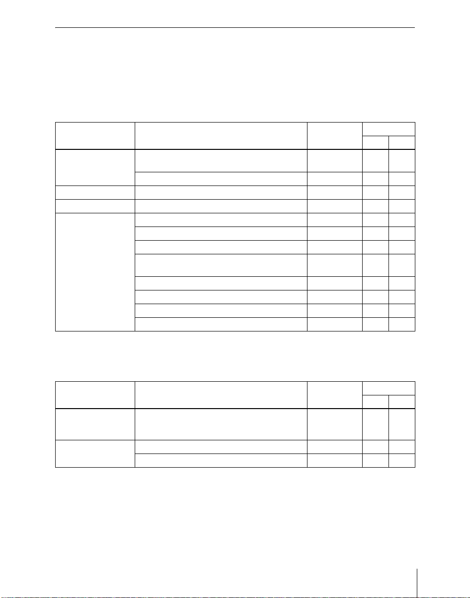
Functions Newly Supported in Vers ion 2.00
The functions newly supported in the DVS-9000/9000SF system
version 2.00
1) For the BKDS-9470: version 1.40
1)
are as follows.
Functions relating to switcher processor
Classification Functions supported Menu No. See page
Vol. 1 V ol. 2
Frame memory Frame memory feed using key processed keyer
signals
Changes in Frame Memory menu 2111 to 2144 348 –
Copy and swap Color data copy and swap relating to DME 3116 81 –
Misc menu Enabling/disabling control from external devices 3211 376 –
Setup User region setting 7331.4 152 238
Logical assignment of PGM/PST to M/E 7331.5 152 238
Through mode for program output/clean output 7333.3 153 242
Preset color mix operation mode 7334.1 40,
Selection of mask and border process priority 7335 153 248
9-pin port device interface setting 7337.1 154 253
KF Reverse Run (GPI input operation) 7337.2 – 255
Enabling/disabling AUX bus control 7337.5 154 258
1115 285
297
153
–
245
Functions relating to DME
Classification Functions supported Menu No. See page
Vol. 1 V ol. 2
Three-dimensional
transform
Special effects Multi move 4122 99 31
Three-dimensional parameter display 4100 and
each DME
menu
Freeze 4131 100 36
97 17
3
Page 4
Functions relating to external devices
Classification Functions supported Menu No. See page
Vol. 1 V ol. 2
External device
control
GPI device control 5311 120 91
VTR/disk recorder control 5331 to 5333 121 94
Functions relating to keyframe effects
Classification Functions supported Menu No. See page
Vol. 1 V ol. 2
Keyframe creation
and execution
Master timeline Master timeline creation and saving 6211 to 6217 139 145
Menu operations Simultaneous operations in multiple regions 6221 to 6227 – 170
a) Not supported by DME.
a)
Keyframe loop – 129 128
Attributes (effect dissolve) 6221 128 150
Functions relating to snapshots
Classification Functions supported Menu No. See page
Vol. 1 V ol. 2
Master snapshot Master snapshot creation and saving 6311 to 6317 140 174
Menu operations Simultaneous operations in multiple regions 6321 to 6357 – 170
Functions relating to utility/shotbox
Classification Functions supported Menu No. See page
Vol. 1 V ol. 2
Utility Utility function execution – 143 178
Shotbox Shotbox register creation from the numeric
keypad control block
Menu operations Simultaneous shotbox register creation in
multiple regions
– – 181
6411.1 – 183
4
Page 5

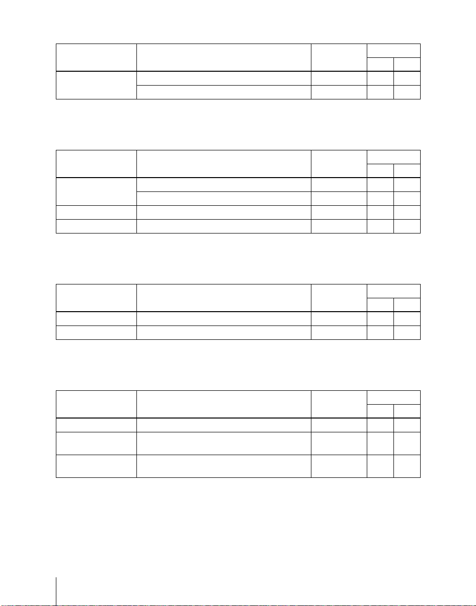
Functions relating to setup
Classification Functions supported Menu No. See page
Vol. 1 V ol. 2
System Master panel for tally control 7312.1 – 197
Key bus delegation button setting (initial status
setting)
Control panels
Xpt Assign Source name and destination name export 7322.5 150 216
Prefs/Utility Button assignment setting 7324 150 218
Device Interface
Operation Setup relating to effects
Maintenance Touch panel calibration 7327 151 233
DCU
Router interface and
tally
Link settings relating internal switcher buses to
Config
routing switcher destinations
Reference module selection for the device
control block
Region selection button assignment for the
numeric keypad control block
Program button assignment setting 7321.8 149 211
Additional actions for GPI input
DCU serial port setting 7325.4 150 226
• Automatic turning off of [EDIT ENBL]
• Automatic insertion of the first keyframe
• Ke y frame duration default value
• Setting whether to replay the first keyframe
after rewinding (GPI/P-BUS/DDR/VTR)
Button operation mode setting
• for during auto transition
• for during keyframe execution
Trackball, joystick and double-click sensitivity
adjustment
Additional actions for GPI input
Serial port setting 7355 155 273
Serial tally setting 7367 156 288
a)
a)
7314 – 200
7321.3 149 207
7321 149 210
7321.7 149 210
7325.1 – 223
7326.2/5/6 150 228
7326.4 151 230
7326.5 151 232
7352 – 267
a) FM1/2 Frame Freeze, FM1/2 Field Freeze, FM1/2 Freeze Off
5
Page 6
Functions relating to files
Classification Functions supported Menu No. See page
Vol. 1 V ol. 2
Menu operations Changes in File menu operations
File import and
export
Directories Directory operations 7171 – 306
• operations between files
• Individual frame memory file operations
Image data import and export for frame memory 7161 159 304
7111 to 7171 158 294
Functions relating to macros
Classification Functions supported Menu No. See page
Vol. 1 V ol. 2
Macros Macro function 5421 160 309
Principal Changes From Version 1.30
The principal changes from version 1.30 are as follows.
Classification Functions changed See page
Vol. 1 Vol. 2
[DEST] button in
the auxiliary bus
control block
Before
change
After
change
While this button is held down,
allocated to the delegation buttons appear in the
selection source name displays.
Press this button,
buses allocated to the delegation buttons in the selection
source name displays.
turning it on, to display the names of
the names of buses
195 –
6
Page 7

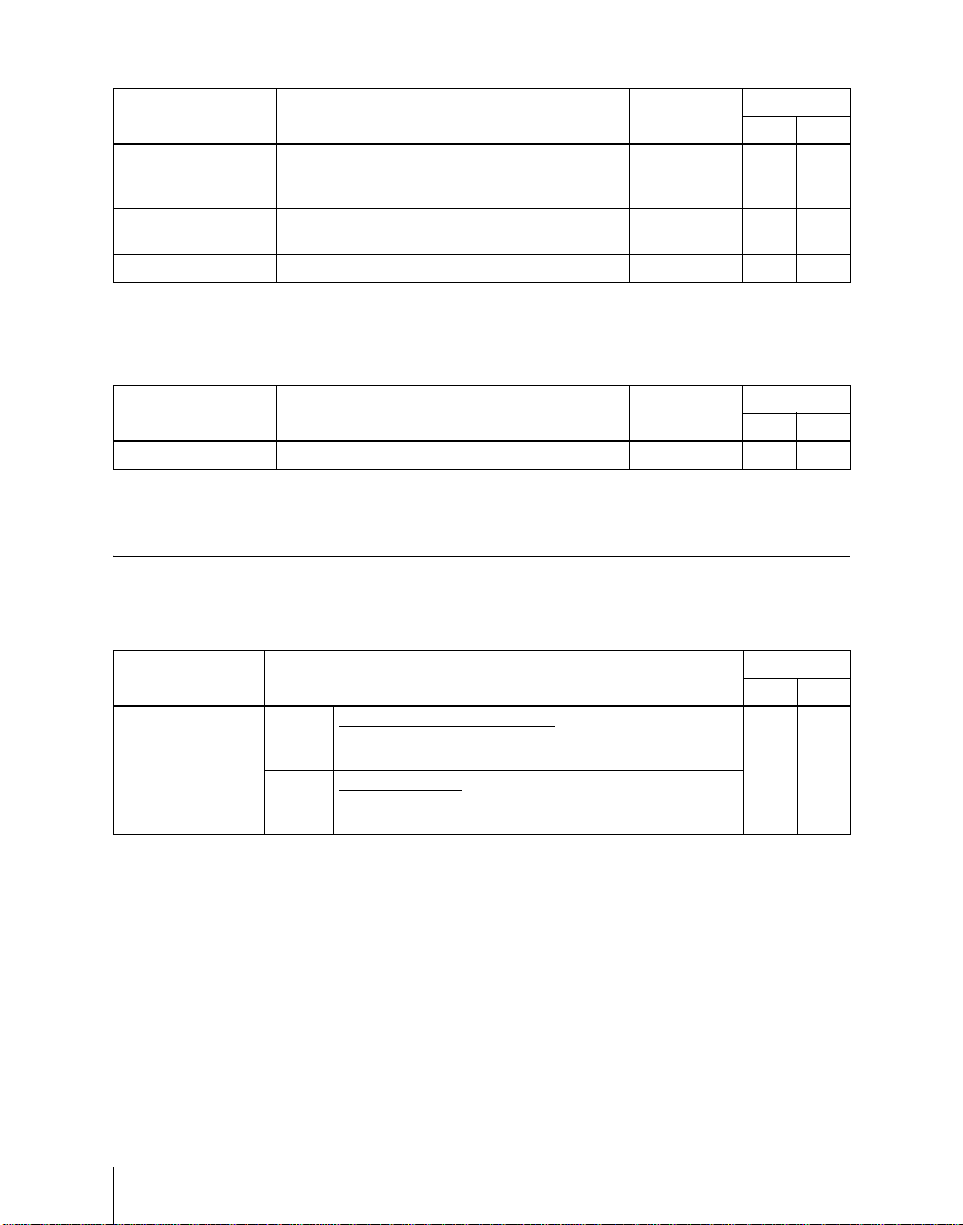
Functions Not Supported in Version 2.00
The following functions are not supported in the DVS-9000/9000SF system
version 2.00.
Classification Functions not supported Menu No. See page
Vol. 1 V ol. 2
DME wipe Additional patterns:
• Frame in-out (No. 1201 to 1204)
• Picture-in-picture (No. 1251, 2651, 2652)
Size and crop adjustment 1165 337 –
Individual modifier adjustment for two-channel
mode patterns
User programmable DME transition mode
setting
DME special effects Beveled edge 4112 99 27
Defocusing of video signal only 4121 98 29
Stardust trail afterimages 4152 110 69
Motion decay 4153 110 70
Keyframe strobe 4154 110 71
Key density 4162 112 75
Key source selection 4162 112 76
DME setup KF Reverse Run (GPI input operation) 7344.1/4 – 262
Macros Macro operations in the numeric keypad control
block
Event creation
•Effect recall
• Snapshot recall
• Ke yframe rewind and run
1161/1162 69 338
1164, 1165 333 –
6114 342 132
– 160 310
– 160 312
340
7
Page 8

8
Page 9

Table of Contents
Chapter 1 DVS-9000 Functions
Introduction ..................................................................................................20
Features of the DVS-9000 Production Switcher System...........................22
Video Processing Flow .................................................................................24
Signal Selection.............................................................................................25
Basics of Signal Selection.....................................................................26
Bus Selection.........................................................................................26
Signal Assignment and Selection..........................................................28
Signal Name Display.............................................................................31
Transitions.....................................................................................................32
Selecting the Next Transition................................................................32
Independent Key Transitions.................................................................35
Transition Types....................................................................................39
Executing a Transition...........................................................................42
Keys................................................................................................................46
Key Types..............................................................................................46
Key Modifiers........................................................................................50
Key Memory..........................................................................................54
Key Snapshots.......................................................................................54
Blink......................................................................................................54
Key Default ...........................................................................................55
Key Modify Clear..................................................................................55
Wipes .............................................................................................................56
Types of Wipe Pattern...........................................................................56
Pattern Mix............................................................................................57
Wipe Pattern Variation and Modifiers..................................................59
Wipe Snapshots.....................................................................................67
DME Wipes...................................................................................................68
Types of DME Wipe Pattern.................................................................68
DME Wipe Pattern Variation and Modifiers.........................................70
Relation Between DME Wipes and Other Effects................................71
DME Wipe Snapshots...........................................................................71
Frame Memory........ .....................................................................................73
Overview...............................................................................................73
9Table of Contents
Page 10

Frame Memory Functions.....................................................................74
Color Backgrounds.......................................................................................78
Copy and Swap.............................................................................................79
Video Process................................................................................................83
Video Process Adjustment of a Primary Input Signal...........................83
Video Process Adjustments on a Particular Bus...................................83
Video Process Memory.........................................................................84
Digital Multi Effects (DME)........................................................................85
Three-Dimensional Transformations.....................................................85
Transformation Operation Modes.........................................................90
Graphics Display...................................................................................95
Three-Dimensional Parameter Display.................................................97
DME Special Effects.............................................................................97
Interpolation ........................................................................................111
Key Density Adjustment.....................................................................112
Key Source Selection ..........................................................................112
Global Effects ......................................................................................112
External Devices .........................................................................................118
Shared Functions for External Device Control...................................118
Control of P-BUS Devices..................................................................119
Control of GPI Devices.......................................................................120
VTR/Disk Recorder Control ...............................................................121
Regions and Registers ................................................................................124
Regions................................................................................................124
Registers..............................................................................................125
Keyframes ...................................................................................................127
Effects..................................................................................................127
Saving and Recalling Effects ..............................................................128
Effect Attributes ..................................................................................128
Effect Editing ......................................................................................128
Time Settings.......................................................................................130
Paths ....................................................................................................133
Effect Execution..................................................................................138
Master Timelines.................................................................................139
Snapshots.....................................................................................................140
Snapshot Types....................................................................................140
Snapshot Attributes .............................................................................141
Utility...........................................................................................................143
Shotbox........................................................................................................144
10
Table of Contents
Page 11

Setup ............................................................................................................145
Overview of Setup...............................................................................145
System Setup.......................................................................................145
Saving and Recalling Setup Data........................................................148
Panel Setup..........................................................................................149
Switcher Setup.....................................................................................151
DME Setup..........................................................................................154
Setup Relating to DCU Input/Output..................................................155
Setup Relating to the Router Interface and Tally Interface.................155
Simple Connection to MKS-8080/8082 AUX Bus Remote Panel......156
Files..............................................................................................................158
Macros.........................................................................................................160
Chapter 2 Menus and Control Panel
Names and Functions of Parts of the Control Panel...............................164
Control Panel: Example Configuration 1
(With Standard Transition Modules) .......................................164
Control Panel: Example Configuration 2
(With Simple Transition Modules)..........................................166
Control Panel: Example Configuration 3
(With Compact Transition Modules).......................................168
Cross-Point Control Block ..................................................................169
Transition Control Block (Standard Type)..........................................173
Flexi Pad Control Block (Standard Type)...........................................177
Key Control Block...............................................................................179
Device Control Block (Trackball).......................................................183
Device Control Block (Joystick).........................................................187
Keyframe Control Block.............. ...... ..... ............................................188
Numeric Keypad Control Block..........................................................191
Fade to Black Control Block...............................................................193
Auxiliary Bus Control Block...............................................................194
Menu Control Block............................................................................197
Memory Card/USB Adaptor Block.....................................................198
Utility/Shotbox Control Block ............................................................199
Transition Control Block and Flexi Pad Control Block (Simple Type)....
200
Independent Key Transition Control Block (Simple Type)................203
Downstream Key Control Block.........................................................205
Transition Control Block (Compact Type) .........................................207
11Table of Contents
Page 12

Basic Menu Operations..............................................................................210
Menu Organization..............................................................................210
Accessing a Menu ...............................................................................215
Interpreting the Menu Screen..............................................................216
Menu Operations.................................................................................217
Chapter 3 Transitions
Basic Operating Procedure........................................................................224
Key Priority Setting....................................................................................227
Setting the Key Priority in the Transition Control Block....................227
Setting the Key Priority by a Menu Operation....................................229
Display of the Key Output Status and Key Priority............................230
Selecting the Transition Type by a Menu Operation..............................232
Super Mix Settings ............................................... ...... ..... ...........................233
Color Matte Settings...................................................................................234
Executing a Transition...............................................................................235
Transition Indicator Function..............................................................235
Setting the Transition Rate..................................................................236
Pattern Limit................................. ...... ..... ............................................239
Executing an Auto Transition..............................................................243
Executing a Transition With the Fader Lever (Manual Transition)....243
Combinations of Auto and Manual Transitions..................................244
Non-Sync State ....................................................................................244
Fader Lever Operation in Bus Fixed Mode.........................................245
Transition Preview .....................................................................................247
Independent Key Transitions....................................................................248
Basic Independent Key Transition Operations....................................248
Setting the Independent Key Transition Type by a Menu Operation ..249
Setting the Independent Key Transition Rate......................................250
Fade to Black...............................................................................................253
Fade to Black Operation......................................................................253
Setting the Fade to Black Transition Rate...........................................253
Simple Transition .......................................................................................255
Basic Operations for Simple Transitions.............................................255
Display of the Key Output Status and Key Priority............................257
Split Fader ...........................................................................................257
Independent Key Transitions With a Simple Transition Module........258
12
Table of Contents
Page 13

Chapter 4 Keys
Key Setting Operations Using Menus.......................................................262
Key Setting Operations With the Key Control Block.............................287
Key Snapshots.............................................................................................299
Key Setting Menus..............................................................................262
Key Type Setting.................................................................................263
Chroma Key Composition...................................................................265
Chroma Key Adjustments...................................................................266
Selecting Key Fill and Key Source ..................................................... 271
Key Edge Modifications......................................................................273
Masks...................................................................................................279
Applying a DME Effect to a Key........................................................283
Specifying the Key Output Destination...............................................284
Blink Function.....................................................................................285
Video Processing.................................................................................286
Operations in the Key Control Block..................................................287
Key Edge Modifications......................................................................291
Masks...................................................................................................295
Applying a DME Effect to a Key........................................................296
Other Key Setting Operations .............................................................297
Key Snapshot Operations....................................................................299
Key Snapshot Operations Using a Simple Transition Module............301
Chapter 5 Wipes
Basic Procedure for Wipe Settings ...........................................................304
Wipe Settings for Independent Key Transitions.....................................322
Wipe Snapshots...........................................................................................327
Wipe Settings Menu............................................................................304
Wipe Pattern Selection........................................................................304
Pattern Mix..........................................................................................307
Setting Wipe Modifiers.......................................................................309
Basic Procedure for Independent Key Transition Wipe Settings........322
Setting Independent Key Transition Wipe Modifiers .........................323
Saving a Wipe Snapshot......................................................................328
Recalling a Wipe Snapshot..................................................................329
Deleting a Wipe Snapshot...................................................................330
13Table of Contents
Page 14

Chapter 6 DME Wipes
Basic Procedure for DME Wipe Settings.................................................332
DME Wipe Settings Menu..................................................................332
DME Wipe Pattern Selection ..............................................................332
Setting DME Wipe Modifiers .............................................................333
DME Wipe Settings for Independent Key Transitions............ ...............339
Basic Procedure for Independent Key Transition DME Wipe Settings....
339
Setting Independent Key Transition DME Wipe Modifiers................340
DME Wipe Snapshots ................................................................................341
Creating User Programmable DME Patterns .........................................342
User Programmable DME Transition Mode.......................................342
Chapter 7 Frame Memory
Frame Memory Operations.......................................................................348
Preparations.........................................................................................348
Interpreting the Frame Memory Menu................................................348
Selecting an Input Image.....................................................................350
Selecting Outputs and Target Frame Memory....................................351
Capturing an Image (Freeze)...............................................................352
Recalling Images.................................................................................354
Image Processing.................................................................................356
Image Output.......................................................................................360
Image Data Management...........................................................................362
Deleting Files ...................................................... ................................362
Renaming Files....................................................................................363
Restoring Files..................................................... ................................364
Chapter 8 Color Backgrounds
Color Background Setting Operations.....................................................368
Color Background Settings Menu.......................................................368
Basic Color Background Setting Operations.......................................368
Chapter 9 Copy and Swap
Basic Copy and Swap Operations.............................................................372
Copy and Swap Menu Operations.......................................................372
Copy by Button Operation ..................................................................373
Table of Contents
14
Page 15

Chapter 10 Misc Menu, Etc.
Misc Menu Operations...............................................................................376
AUX Menu Operations ..............................................................................378
AUX Bus Settings ...............................................................................378
Video Process Settings................................................................................379
Index ............................................................................................................381
15Table of Contents
Page 16

16
Table of Contents
Page 17

Chapter 1 DVS-9000 Functions
Introduction............................................................................................. 20
Features of the DVS-9000 Production Switcher System.....................22
Video Processing Flow............................................................................24
Signal Selection.......................................................................................25
Basics of Signal Selection ................................... ..... ....................... 26
Bus Selection................................................................................... 26
Signal Assignment and Selection.................................................... 28
Signal Name Display.......................................................................31
Transitions...............................................................................................32
Selecting the Next Transition..........................................................32
Independent Key Transitions...........................................................35
Transition Types.................................................. ............................ 39
Executing a Transition.....................................................................42
Keys..........................................................................................................46
Key Types........................................................................................ 46
Key Modifiers..................................................................................50
Key Memory....................................................................................54
Key Snapshots .................................................................................54
Blink ................................................................................................ 54
Key Default......................................................................................55
Key Modify Clear............................................................................ 55
Wipes........................................................................................................56
Types of Wipe Pattern.....................................................................56
Pattern Mix......................................................................................57
Wipe Pattern Variation and Modifiers.............................................59
Wipe Snapshots ............................ ...... ..... ........................................ 67
DME Wipes .............................................................................................68
Types of DME Wipe Pattern........................................................... 68
DME Wipe Pattern Variation and Modifiers................................... 70
Page 18

Relation Between DME Wipes and Other Effects..........................71
DME Wipe Snapshots ..................................................................... 71
Frame Memory .......................................................................................73
Overview .........................................................................................73
Frame Memory Functions ...............................................................74
Color Backgrounds.................................................................................78
Copy and Swap .......................................................................................79
Video Process ..........................................................................................83
Video Process Adjustment of a Primary Input Signal.....................83
Video Process Adjustments on a Particular Bus ............................. 83
Video Process Memory ...................................................................84
Digital Multi Effects (DME) ........................................... ....................... 85
Three-Dimensional Transformations...............................................85
Transformation Operation Modes ...................................................90
Graphics Display .............................................................................95
Three-Dimensional Parameter Display ...........................................97
DME Special Effects.......................................................................97
Interpolation...................................................................................111
Key Density Adjustment ............................................................... 112
Key Source Selection..................................................................... 112
Global Effects................................................................................ 112
External Devices....................................................................................118
Shared Functions for External Device Control..............................118
Control of P-BUS Devices ............................................................ 119
Control of GPI Devices ................................................................. 120
VTR/Disk Recorder Control..........................................................121
Regions and Registers........................................................................... 124
Regions.......................................................................................... 124
Registers ........................................................................................125
Page 19

Keyframes..............................................................................................127
Effects............................................................................................ 127
Saving and Recalling Effects................................................ ..... ....128
Effect Attributes ............................................................................ 128
Effect Editing................................................. ...... ..... ..................... 128
Time Settings.................................................................................130
Paths...............................................................................................133
Effect Execution ..................... ...... .................................................138
Master Timelines...........................................................................139
Snapshots............................................................................................... 140
Snapshot Types......................................................... ...... ............... 140
Snapshot Attributes.................................. ...... ...... .......................... 141
Utility ..................................................................................................... 143
Shotbox.................................................................................................. 144
Setup....................................................................................................... 145
Overview of Setup......................................................................... 145
System Setup .................................................................................145
Saving and Recalling Setup Data ......................................... ......... 148
Panel Setup .................................................................................... 149
Switcher Setup............................................................................... 151
DME Setup .................................................................................... 154
Setup Relating to DCU Input/Output............................................155
Setup Relating to the Router Interface and Tally Interface........... 155
Simple Connection to MKS-8080/8082 AUX Bus Remote Panel 156
Files ........................................................................................................ 158
Macros ...................................................................................................160
19
Page 20

Introduction
This manual is the User’s Guide for the DVS-9000/9000SF Production
Switcher system supporting the SDTV signal format only. The DVS-9000 and
Chapter 1 DVS-9000 Functions
Devices and system nomenclature
DVS-9000SF have different numbers of M/E banks and input/output signals,
but are otherwise functionally identical.
This manual refers to these generically as the “DVS-9000 system,” and
describes principally the operat ion of the sys tem using the CCP-8000 series of
center control panels.
The User’s Guide for the DVS-9000 system comprises two volumes.
Contents of Volume 1
Overview of functions of the DVS-9000 sys tem, and basic swi tcher operatio ns
including transitions, keys, and wipes.
Contents of Volume 2
DME effects, snapshots, keyframes, and various operations such as setup
which affect the overall system.
In this manual, when discussing the principal components of the DVS-9000
system, in place of the formal product names, abbreviated names
characterizing the functions and features are sometimes used. When
distinctions between system configurations must be drawn, the term s in the
second table on this page are used.
20
Introduction
Principal components and naming
The formal product names of the principal components of the DVS-9000
system, and the terms used in this manual are as follows.
Formal product name Term used in this manual
DVS-9000/9000SF Production Switcher
Processor
BKDS-9470 DME Board Set DME or DME board set
CCP-8000-series Center Control Panel Control panel or center control panel
DCU-8000 Device Control Unit DCU
Switcher or switcher processor
System nomenclature
The following terms are used for systems, depending on the combination of
installed options, and the signal format.
Page 21

System configuration and features Term for system
A system in which the center control panel has
four M/E banks
A system in which the center control panel has
three M/E banks
A system in which the center control panel has
two M/E banks
Related manuals
The following manuals are supplied with the individual products of the DVS9000 Production Switc her sy st em.
DVS-9000/9000SF-C Switcher Processor Pack
• DVS-9000/9000SF-C Operati on Manual
• DVS-9000/9000SF-C Installa t ion Manual
BKDS-9470 DME Board Set
• BKDS-9470 Operation Manual
• BKDS-9470 Installation Manual
CCP-8000 Center Control Panel Pack
• CCP-8000 Operation Manual
• CCP-8000 Installation Manual
DCU-8000 Device Control Unit Pack
• DCU-8000 Operation Manual
• DCU-8000 Installation Manual
4M/E system
3M/E system
2M/E system
Chapter 1 DVS-9000 Functions
21Introduction
Page 22

Features of the DVS-9000 Production Switcher System
Chapter 1 DVS-9000 Functions
The DVS-9000 Production Switcher system boasts extensible high
performance and multifunctionality. The following are some of the principal
features of this system.
System configuration flexibility
SDTV support
This system supports the SDTV signal formats 480i/59.94 and 576i/50. The
format selection can be switched by a simple control panel operation.
Extensible system configuration
By suitable combination of options, the switcher can be configured with
various inputs and outputs, and different numbers of M/E banks. The syste m
offers the flexibility to change and expand as required.
When the optional DME board set is installed, the system allows you to use up
to four DME channels.
Powerful external device inte rface s
By connecting to a Sony routing switcher or similar, a large system can be
built. From the control panel, it is also possible to operate other equipment,
including VTRs and disk recorders.
Powerful tally system
The complete system including routing switcher provides an all-inclusive tally
system. The system can be adapted to different applications and settings, using
multiple tally outputs, including both on-air and recording tallies.
Comprehensive video manipulation
M/E banks
Each mix/effects bank (M/E bank) is equipped with four keyers, and each
keyer is capable not only of chroma keying, but also independent key
transitions separate from the background transitions. The four keys can be
freely combined, to carry out four different program outputs.
Features of the DVS-9000 Production Switcher System
22
Page 23

Powerful frame memory functions
The frame memory can store 222 frames, and up to eight of these can be
recalled simultaneously.
Link operation with DME
Using the BKDS-9470 DME Bord Set, a range of DME functions including
DME wipes and processed keys can be handled as switcher functions.
The system can interface with up to four DME units.
Designed for use in a live broadcasting en vir onment
Flexible control panel layout
Because of its modular design, the variou s sectio ns of the control pa nel can be
laid out as required. This allows a flexible layout appropriate to the system
operation.
High-performance user interface
The menu control block provides a large color LCD panel, with rapid touchpanel menu sel ection.
The source name displays and buttons in the Flexi Pad
have color backlit LCD displays. The signal names, and graphical
representations of the patterns associated with buttons provide intuitive
feedback, and allow the immediate decisions that are required in a live
operating environment.
TM
and shotbox sections
Chapter 1 DVS-9000 Functions
23Features of the DVS-9000 Produc tion Switcher System
Page 24
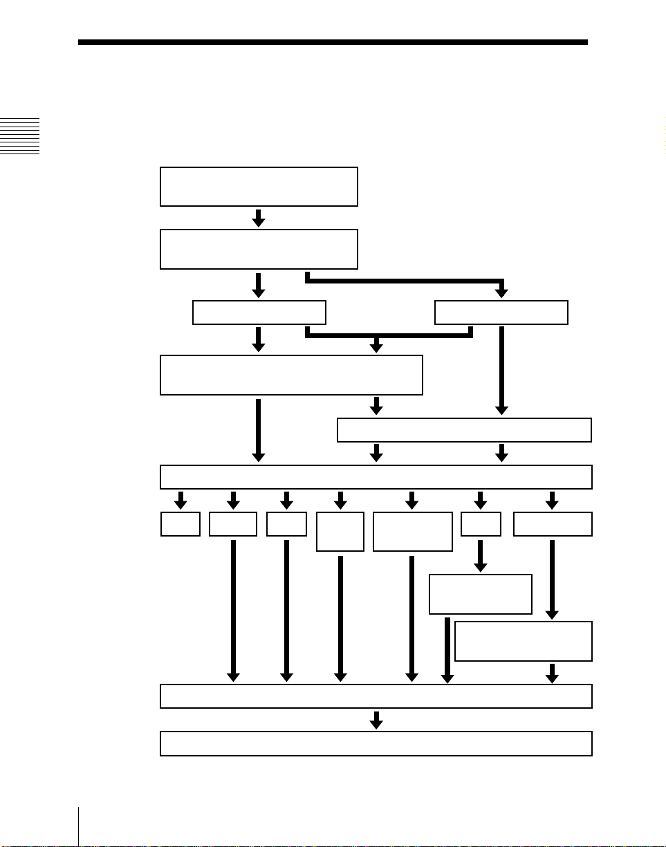
Video Processing Flow
The following illustration shows the flow of operations for carrying out a
transition on an M/E bank or the PGM/PST bank.
Chapter 1 DVS-9000 Functions
]
Select current background video
(page 25)
Select next transition (page 32)
Background
Select new background video (page 25)
Select transition type (page 39)
Cut Mix
NAM
Preview the effect of transition (page 44)
Super
mix
Keys 1 to 4
Make key settings (page 46)
Preset color
mix
Wipe
Make wipe
settings (page 56)
Make DME wipe settings
(page 68)
DME wipe
Video Processing Flow
24
Execute the transition (page 42)
Page 25
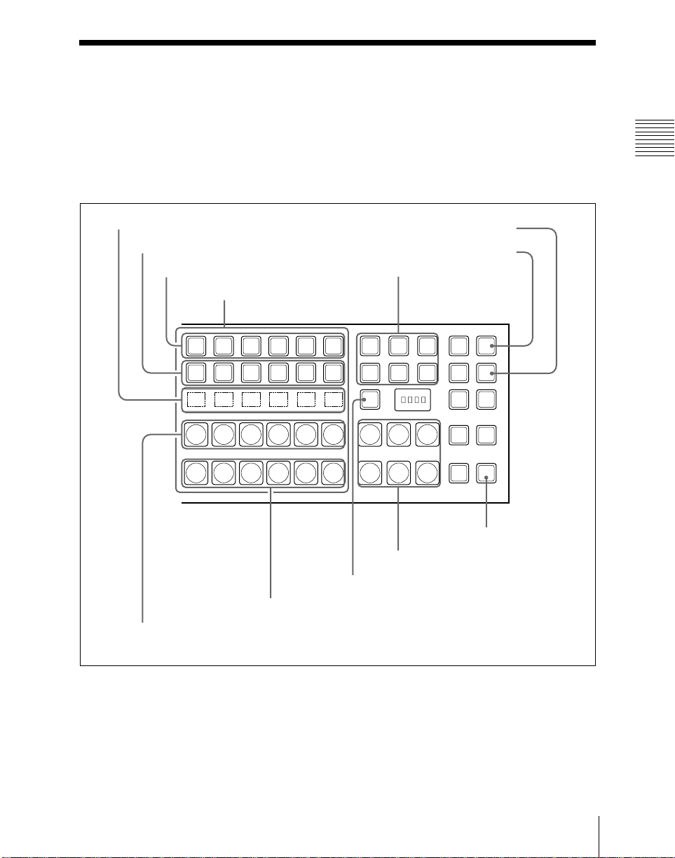
Signal Selection
You carry out signal selection with the cross-point buttons in the cross-poin t
control block of each M/E bank or the PGM/PST bank, and the buttons in the
auxiliary bus control block.
The number of buttons in each cross-point row may be 16, 24, or 32, but here
the description is of the 32-button case as an example.
Chapter 1 DVS-9000 Functions
Source name displays
Key 2 row
Key 1 row
Background A row
Cross-point buttons
Background B row
Reentry buttons
M/E
SHIFT
1
M/E
SHIFT
1
SHIFT
M/E
SHIFT
1
M/E
SHIFT
1
Reentry buttons
SHIFT button
KEY4 button
KEY3 button
M/E
2
M/E
2
M/E
2
M/E
2
XPT
M/E
3
M/E
3
M/E
3
M/E
3
HOLD
HOLD
MCRO
ENBL
HOLD
HOLD
KEY3
XPT
KEY4
MCRO
ASGN
XPT
AUTO
RUN
XPT
UTIL
UTIL button
Cross-point control block
25Signal Selection
Page 26

Basics of Signal Selection
Each of the M/E bank, P GM/PS T b ank and auxiliary bus control block has 32
cross-point buttons and three reentry buttons (four in the case of the auxiliary
bus control block).
These buttons are identified by nu mbers common to all of the banks and b lock,
Chapter 1 DVS-9000 Functions
and a signal is assigned to each number.
The basis of signal selection is to select, in a cross-point button row, the crosspoint button to which is assigned the desired signal.
Reentry buttons
To use the output of one M/E bank as background input to another bank, use
the reentry buttons [M/E1], [M/E2], and [M/E3] (on the auxiliary bus control
block, [M/E1], [M/E2], [M/E3], and [PGM]) in the cross-point control block
of the destination bank.
For example, to feed the output fro m the M/E-1 bank as the backgroun d B input
to M/E-2, in the M/E-2 cross-point control block, press the [M/E1] button in
the background B row.
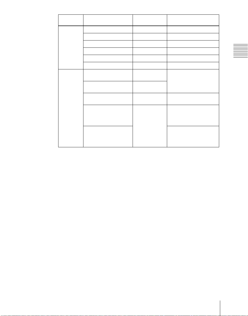
Bus Selection
Each row of 32 cross-point buttons is shared by multiple buses.
For example, in the M/E-1 b ank, the key 1 row of buttons can be assigned either
to the key 1 bus or to the key 3 bus . The [KEY3] button switches between these
two assignments.
To assign a bus to the cross-point buttons in the auxiliary bus control block,
press one of the AUX delegation buttons to select the bus.
26
Signal Selection
The following table illustrates the correspondence between buses and crosspoint button rows, and the delegation operations.
Bank Bus name Cross-point
M/E-1,
M/E-2,
M/E-3
Background A bus Background A
Background B bus Background B
Key 1 bus Key 1 row Turn off the [KEY3] button
Key 2 bus Key 2 row Turn off the [KEY4] button
Key 3 bus Key 1 row Turn on the [KEY3] button
Key 4 bus Key 2 row Turn on the [KEY4] button
button row
row
row
Delegation operation
−
−
Page 27
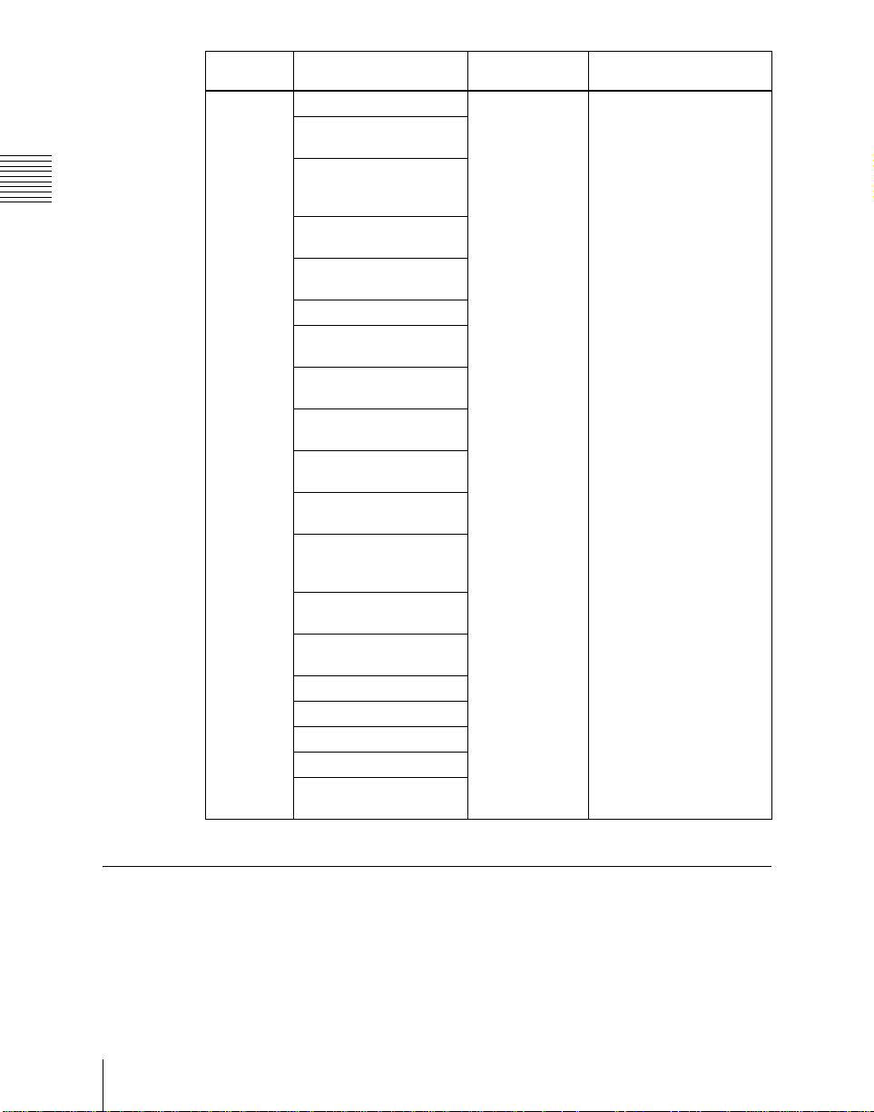
Bank Bus name Cross-point
PGM/PST Program bus Program row −
Preset bus P reset row −
DSK 1 bus DSK1 row Turn off the [DSK3] button
DSK 2 bus DSK2 row Turn off the [DSK4] button
DSK 3 bus DSK1 row Turn on the [DSK3] button
DSK 4 bus DSK2 row Turn on the [DSK4] button
M/E-1,
M/E-2,
M/E-3,
PGM/PST
Utility 1 bus Background A
Utility 2 bus Background B
DME external video bus Key 1 row Hold down the [UTIL]
DME utility 1 bus Key 2 row Hold down the [UTIL]
DME utility 2 bus Hold down the [UTIL]
button row
row
row
Delegation operation
Chapter 1 DVS-9000 Functions
When [UTIL] button mode
is Hold, hold down the
[UTIL] button
button
button, and press the
[KEY4] button, turning it
off
button, and press the
[KEY4] button, turning it
on
27Signal Selection
Page 28
Bank Bus name Cross-point
Auxiliary
bus control
block
Chapter 1 DVS-9000 Functions
AUX1 to AUX48 buses 1st row, 2nd row Turn on the appropriate
MONITOR 1 to
MONITOR 8 buses
Frame memory source 1
and frame memory
source 2 buses
DME 1 to DME 4 video
buses
DME 1 to DME 4 key
buses
Edit preview bus
M/E-1 UTILITY 1 and
M/E-1 UTILITY 2 buses
M/E-2 UTILITY 1 and
M/E-2 UTILITY 2 buses
M/E-3 UTILITY 1 and
M/E-3 UTILITY 2 buses
P/P UTILITY 1 and P/P
UTILITY 2 buses
M/E-3 Key 1 fill to M/E-3
Key 4 fill buses
M/E-3 Key 1 source to
M/E-3 Key 4 source
buses
DSK 1 fill to DSK 4 fill
buses
DSK 1 source to DSK 4
source buses
M/E-1 external DME bus
M/E-2 external DME bus
M/E-3 external DME bus
P/P external DME bus
DME UTILITY 1 and
DME UTILITY 2 buses
button row
Delegation operation
buttons in accordance with
the signal assignment
made in the Setup menu.
Signal Assignment and Selection
Assigning signals to buttons
Each of the 32 cross-point buttons and reentry buttons has a corresponding
button number, to which you assign a signal.
Signal Selection
28
Page 29
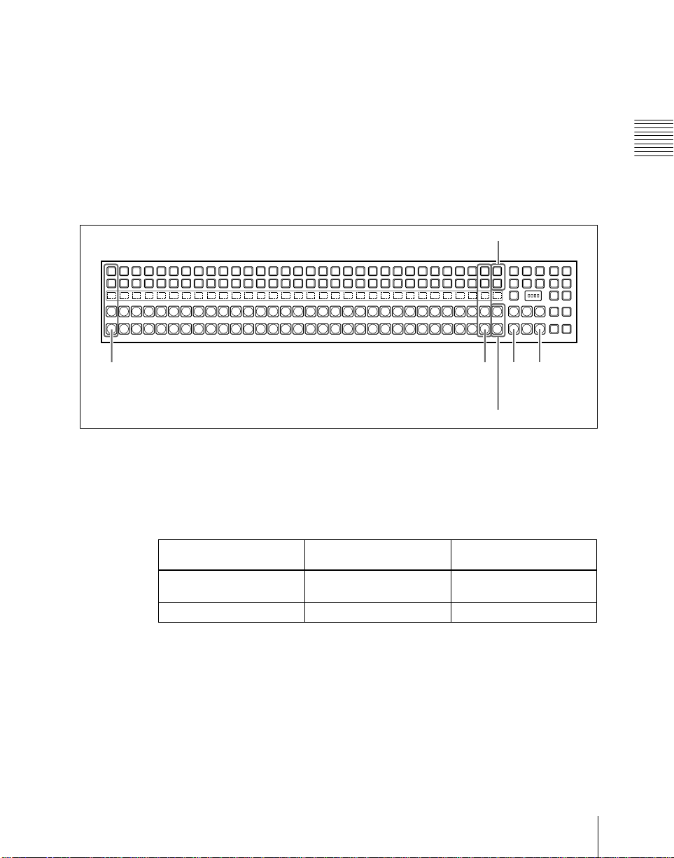
In addition to the signals input to the PRIMARY INPUTS 1 to 80 connectors
on the rear panel of the switcher, you can also select signals generated within
the switcher.
Each button has assigned to it a video signal and a key signal, forming a pair.
You can set these video and key combinations in a Setup menu.
For details of Setup menu operations, see “Cross-Point Settings (Xpt Assign
Menu)” in Chapter 16 (Volume 2).
Cross-point button control block button numbers
Shift button
M/E
1
M/E
1
SHIFT
M/E
1
M/E
1
Chapter 1 DVS-9000 Functions
XPT
M/E
M/E
DSK3
HOLD
2
3
XPT
M/E
M/E
KSK4
HOLD
2
3
MCRO
MCRO
ENBL
ASGN
M/E
M/E
XPT
AUTO
2
3
HOLD
RUN
M/E
M/E
XPT
UTIL
2
3
HOLD
1, 2, 3, 4, ....... ....... 29, 30, 31 121 123
32, 33, 34, 35, ....... ....... 60, 61, 62 125 127
(first button numbers)
(second button numbers)
Shift but to n
On each M/E bank and the PGM/PST bank, each cross-point button and reentry
button has two butto n numbers, and you us e the shift bu tton to sw itch between
these numbers.
In the case of a 32-button layout, the button numbers are as follows.
Cross-point control block button numbers
Button Number when the shift
button is not pressed
From the left end to the 31st
1 to 31 32 to 62
Number when the shift
button is pressed
button
Reentry buttons 121 to 123 125 to 127
Switching button numbers
The rightmost (32nd) button functions as a shift button.
(The shift button function can be disabled in a Setup menu.)
When selecting the signals of button numbers 1 to 31, press the cross-point
button for the desired signal.
To select button numbers 32 to 62, hold down the shift button, and press the
cross-point button for the desired signal.
29Signal Selection
Page 30
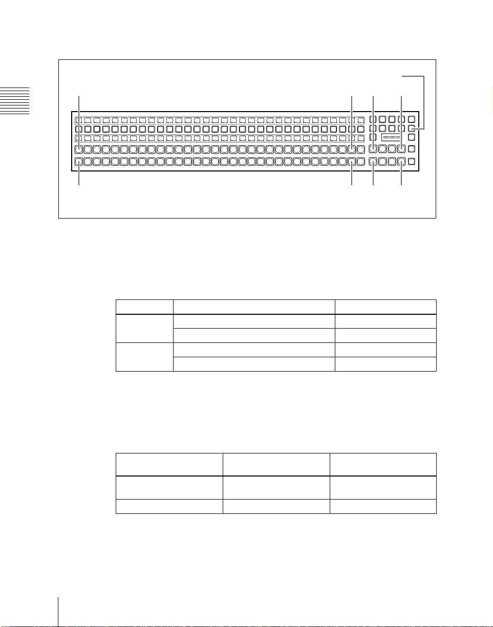
Button numbers in the auxiliary bus control block
2ND button
1, 2, 3, 4, ....... ....... 29, 30, 31 121 124
(1st row)
Chapter 1 DVS-9000 Functions
AUX1AUX2AUX3AUX4AUX5AUX6AUX7AUX8AUX9AUX10AUX11AUX12AUX13AUX14AUX15AUX16AUX17AUX18AUX19AUX20AUX21AUX22AUX23AUX24AUX25AUX26AUX27DME
32, 33, 34, 35, ....... ....... 60, 61, 62 125 128
(2nd row)
UTIL1
DME
UTIL2FM1FM2
LEVEL
LEVEL
LEVEL
LEVEL
1
EDIT
DEST
PVW
SHIFT
M/E
1
M/E
1
RTR
2
3
4
MCRO
MCRO
MCRO
2ND
1
2
3
KEY
XPT
M/E
M/E
P/P
HOLD
2
3
XPT
M/E
M/E
P/P
HOLD
2
3
When the [2ND] button is unlit
The cross-point buttons and reentry buttons in the auxiliary bus control block
have separate upper (1st row) and lower (2nd row) numbers.
In the case of a 32-button layout, the button numbers are as follows.
Auxiliary bus control block button numbers ([2ND] button unlit)
Button Button Button numbers
1st row From the left end to the 31st button 1 to 31
Reentry buttons 121 to 124
2nd row From the left end to the 31st button 32 to 62
Reentry buttons 125 to 128
When the [2ND] button is lit
Different buses can be assigned to the 1st-row buttons and 2nd-row buttons.
When the 32nd button is set as a shift button, the 1st-row buttons and 2nd-row
buttons both have the following button numbers.
Auxiliary bus control block button numbers ([2ND] button lit)
30
Signal Selection
Button Number when the shift
button is not pressed
From the left end to the 31st
1 to 31 32 to 62
Number when the shift
button is pressed
button
Reentry buttons 121 to 124 125 to 128
Page 31

Signal Name Display
You can attach a name (source name) to each signal assigned to a cross-point
button, with a maximum of 16 characters.
• The source name dis plays i n th e cros s -po in t con tr ol bl o ck an d auxiliary bus
control block show the source names of the video signals assigned to
numbers 1 to 31.
• To display the source names for numbers 32 to 62, press the [SHIFT] bu tton
to the right of the source name displays.
• To display the source names of the key signals assigned to buttons, hold
down the [Split] button in the key control block or the [KEY] button in the
auxiliary bus control block.
Colors of lit cross-point buttons
In a particular row of cross-point buttons, only the last pressed button is
effective, and lights amber or red. The amber indicates the “low tally” state,
and the red indicates the “high tally” state, to indicate whether or not the
selected signal appears in the final output video.
Color State Significance
Amber Low tally Does not appear in final output video
Red High tally Appears in final output video
Chapter 1 DVS-9000 Functions
Significance of colors of lit cross-point buttons
31Signal Selection
Page 32

Transitions
In the M/E banks and PGM/PST bank, the switch from the current video stream
(appearing on the corresponding program monitor) to a new video stream is
Chapter 1 DVS-9000 Functions
Selecting the Next Transition
Changing the background
referred to as a transition.
To execute a transition, it is first necessary to decide how the image will be
changed as a result of the transition. This selection is carried out using the next
transition selection buttons (see p age 173) in the transition control block of the
M/E or PGM/PST bank.
For details of operations, “Basic Operating Procedure” (page 224).
In the M/E banks and PGM/PST bank, you can change one of the images, the
background, and keys 1 to 4 (do wns tr eam keys 1 t o 4 i n the P GM/PS T bank ),
and also vary combinations of these simultaneously.
The following are examples of transition.
A background transition switches from the video currently selected on the
background A bus (the current video) to the video selected on the backg round
B bus (the new video).
32
Transition
Background BBackground A
In the default selection of flip-flop mode (see page 43), the b ackground alway s
switches in the direction from the A bus to the B bus. When the transition
completes, the cross-point selections on the A and B buses are interchanged.
Transitions
Page 33

Inserting and deleting a key
You can insert one or more of the four keys (downstream keys on the PGM/
PST bank).
If you select a key which is already inserted, the transition will delete the key.
A simultaneous combination of deleting and inserting keys is also possible.
Key 1
Insert
Delete
Inserting or deleting key 1 and key 2
Transition
Key 1
Key 2
Key 2
Chapter 1 DVS-9000 Functions
Deleting key 1 and inserting key 2
33Transitions
Page 34

Simultaneously changing the background and keys
You can change any of the four keys (downstream keys on the PGM/P ST bank)
and the background at the same time.
Key 1
Chapter 1 DVS-9000 Functions
Transition
Key 2
Changing the background and key 2 simultaneously
Key 1
Selecting the key priority
If a number of keys are already inserted in the current video , you can check or
change the key priority, th at i s to say , the ord e r in wh i ch the keys are overlaid.
When a key priority ([KEY PRIOR]) is selected as the next trans ition, you can
also change the key priority in the new video.
For details of this operation, see “Key Priority Setting” (page 227).
Transitions
34
Transition
Key 2
Changing the background and keys 1 to 4 simultaneously
Key 3
Key 4
Page 35

The key priority values go from 1 to 4, with a higher priority key being “in
front” as seen on the screen.
1
2
3
4
Priority sequence on the screen
Independent Key Transitions
What is an independent key transition?
In addition to common transitions, it is possible to carry out independent
transitions on the keyers of the M/E banks and PGM/PST bank. These are
called “independent key transitions.”
By carrying out an independent key transition in combination with a common
transition, different transition types can be used for the background and keys.
It is also possible to use different transition types for key insertion and key
deletion by m eans of a Setup men u setting.
Chapter 1 DVS-9000 Functions
For details of this operation, see “Basic Independent Key Transi tion
Operations” (page 248).
The following description compares the independent key transition with a
common transition, taking a simultaneous change of the background and key
as an example.
Video used in the transition
Background A
Background B
Key to insert
35Transitions
Page 36

Effect of a common transition
In the case shown in the above illustration, carrying out a common transition
produces the following change in the image.
Chapter 1 DVS-9000 Functions
Transition type: wipe
Effect of a common transition
Same wipe is applied to
background and key.
Effect of use with an independent key transition
The key is inserted with an independent key transition as the background
changes with a common transition, providing the following resu lt.
Transition type:
wipe
Effect of a background transition and independent key transition
Independent key
transition typ e:
wipe
Different wipe patterns are applied to
the background and key transitions.
Combining other transitions with independent key transitions
When you set a common transition and a key independent transition for the
same key, you can apply two different effects such as a wipe and mix (dissolve)
(see page 39) to the key simultaneously.
When carrying out such a combination of transitions simultaneously on a key
as auto transitions (see page 42), the result depends on the timing of pressing
the respective [AUTO TRANS] buttons.
36
Transitions
Page 37

Simultaneous execution
If the [AUTO TRANS] buttons for the two transitions are pressed
simultaneously, the following is the result.
Note that in both cases the common transition is a wipe and the independent
key transition is a mix (dissolve).
Deleting a key with simultaneous transitions: With the key inserted, it is
deleted simultaneously with the two transitions.
When the common transition completes, even if the independent key
transition is still not completed, the two end simultaneously.
Chapter 1 DVS-9000 Functions
Wipe and mix
(dissolve) are
carried out
simultaneously
Deleting a key with simultaneous transitions
The key is deleted,
even if the
independent key
transition has not
completed.
Inserting a key with simultaneous transitions: With the key not inserted, it
is inserted simultaneously with the two transitions. If the common
transition or independent key transition ends first, the other continues to
completion.
Wipe and mix
(dissolve) are
carried out
simultaneously
Inserting a key with simultaneous transitions
The transitions
continue until both
are completed.
Time offset execution
If the [AUTO TRANS] buttons for the two transitions are pressed with a time
offset, the following is the result.
Note that in both cases the common transition is a wipe and the independent
key transition is a mix (dissolve).
37Transitions
Page 38

Time offset execution with the key inserted: With the key inserted, it is
deleted with the two transitions acting with a time offset.
Whichever button is pressed first, when the common transition completes,
even if the independent key transition is still not completed, the two end
simultaneously.
Example: When the independent key transition [AUTO TRANS] button
is pressed later
Chapter 1 DVS-9000 Functions
The key is deleted,
Common transition
(wipe) start
Time offset execution with the key inserted
Independent key
transition (mix) start
even if the
independent key
transition has not
completed.
Time offset execution with the key not inserted: With the key not inserted,
it is inserted with the transition whose [AUTO TRANS] button is pressed
first.
Since the key is then in the inserted state, with the transition whose [AUTO
TRANS] button is pressed later, the key is deleted. When the key is
completely deleted, both transitions complete.
38
Transitions
Page 39

Example 1: When the independent key transition [AUTO TRANS]
button is pressed later
Example 2: When the common transition [AUTO TRANS] button is
pressed later
Transition Types
Selecting the transition type determines the way in which the transition occurs.
Carry out the type selection with the transition type selection buttons in the
transition control block of the M/E or PGM/PST bank.
For details of this operation, see “Basic Operating Procedure” (page 224).
The transition
Common transition
(wipe) start
Independent
key transition
(mix) start
Time offset execution with the key not inserted
Independent key
transition (mix)
start
Common
transition (wipe)
start
completes with the
key deleted.
The transition
completes with the
key deleted.
Chapter 1 DVS-9000 Functions
Mix
The following are the transition types.
This is a dissolve, in which the new video progressively fades in over the
current video, with the sum of the two video outputs maintained constant. At
the mid-point of the transition (when the fader lever is in the center position) ,
the output of each is 50%.
This transition type can also be selected for an independent key transition. In
this case, the key either dissolves in or dissolves out similarly, with the
progress of the transition.
39Transitions
Page 40

NAM (non-additive mix)
In this dissolve, the current video and new video signals are compared, and the
signal with the higher luminance level is given priority in the output. The
current video is maintained at 100% output for the first half of the transition as
the new video increases progressively to 100%, then the current video is
progressively reduced f rom 100% to zero in t he second half with the new video
Chapter 1 DVS-9000 Functions
maintained at 100% output.
Note
This transition type is not available for an independent key transition.
Super mix
In this dissolve, the current video is maintained at 100% output for the first half
of the transition as the new video is mixed while increasing progressively to
100%, then the current video is progressi vely reduced from 100% to zero in the
second half with the new video maintained at 100% output.
Note that you can set the output levels of the current and new vi deo signal s at
the mid-point of the transition, in the range 0 to 100%. (See “Super Mix
Settings” (page 233).)
Note
This transition type is not available for an independent key transition.
Preset color mix
Transitions
40
This is a two-stage dissolve, comprising two transitions, the first a dissolve to
a color matte, and the second from the color matte to the new video.
In the first transition, the current video is replaced by the color matte in a mix
(dissolve), then in the second transition the co lor matte is rep laced b y the new
video also in a mix (dissolve). You can specify the color matte by luminance,
saturation, and hue values. (See “Color Matte Settings” (page 234).)
Notes
• This transition type is not available for an independent key transition.
• In the bus fixed mode, a preset color mix cannot be used.
One-stroke mode and one-time mode
• You can make a setting such that a preset color mix is carried out in a single
transition. This is called “one-stroke mode.”
• You can also make a setting such that when a preset color mix is completed,
the next transition switches to the previous transition type automatically.
This is called “one-time mode.”
Page 41

When only the background is changed
Current video
Preset color mix (changing background only)
Color matte
New video
When a key is inserted
Key fades out
Key
Preset color mix (transition including key)
When a key is
selected as the next
transition
When no key is selected
Key fades in
By means of a Setup menu setting, it is possible to preserve the key state while
carrying out the color matte mix.
When, with a key inserted, a key is selected in the next transition
Chapter 1 DVS-9000 Functions
Wipe
Key state preserved
Key
Preset color mix (when set to preserve key state)
Key gradually
removed
A wipe replaces the current video by the new video according to a
predetermined pattern. This transition type can also be selected for an
independent key transition.
For details, see “Wipes” (page 56) and Chapter 5 “Wipes” (page 303).
41Transitions
Page 42

DME wipe
Using a DME effect, it is possible to obtain a transition to a new image from
the current image, as in a wipe. You can also use this transition type as an
independent key transition.
For details, see “D ME Wi pes” (pa ge 68) and C hapt er 6 “DME Wipes ” (page
Chapter 1 DVS-9000 Functions
331).
Note
To carry out DME wipes requires the BKDS-9470 DME Board Set.
Cut
A cut switches instantaneously from the current video to the new video. When
the next transition is a key transition, the key cuts in or out instantaneously.
Executing a Transition
There are two modes of executing a transition: an auto transition by button
operation or a manual transition using the fader lever.
It is also possible to combine both methods, taking control with the fader lever
of an auto transition which has partly completed, or complete a transition
started with the fader lever as an auto transition.
By combining common transitions with independent key transitions, different
transition types can be applied to the background and keys, for example
allowing a key wipe co mbined wi th a back groun d diss olve. (See “Executing a
Transition” (page 235).)
Auto transitions
Transitions
42
Cut
A cut switches instantaneously from the current video to the new video. When
the next transition is a key transition, the key cuts in or out instantaneously.
Auto transition
The transition from the current video to the new video is carried out
automatically at a constant rate, using the transition effect selected as the
transition type.
You can set the transition rate in advance. (See “Setting the Transition Rate”
(page 236).)
Page 43

Manual transitions
Using the fader lever, you can manually control the progress of the transition.
Moving the fader lever from one end of its travel to the other completes the
transition.
Flip-flop mode and bus fixed mode
The following describes the difference between flip-flop mode and bus fixed
mode, taking an M/E bank as an example; the functionality is the same,
however, on the PGM/PST bank.
Normally, when a background transition is carried out on an M/E bank, the
signals selected on the A and B rows of cross-poin t buttons are interchanged at
the end of the transition. That is to say, except during a transition, the
background output is always from the background A bus. This is called “flipflop mode.”
The alternative is known as “bus fixed mode,” in which there is no bus
interchange. In this mode, when the fader lever is at the top of its travel the
output from the A bus is always 100%, and when the fader lever is at the bottom
of its travel the output from the B bus is 100%.
BLACK
A
BLACK
B
Buttons lit
Fader
lever
BLACK
A
BLACK
B
BLACK
A
BLACK
B
Chapter 1 DVS-9000 Functions
Flip-flop mode
Bus fixed mode
Flip-flop mode and bus fixed mode
For details of fader lever operation in bus fixed mode, see page 245.
43Transitions
Page 44

Transition preview
With the preview output of the M/E banks and PGM/PST bank, you can check
the effect of a transition in advance. To carry out a transition preview, press the
[TRANS PVW] button in the transition control block. (See “Transition
Preview” (page 247).)
Chapter 1 DVS-9000 Functions
Note
In multi-program mode, DSK mode (page 152) or bus fixed mode (pag e 43),
it is not possible to carry out a transition preview.
Pattern limit
When a wipe or DME wipe pattern is selected for the transition, you can
specify the range of movement of the wipe pattern through the course of the
transition, for each bank independently.
When the pattern limit function is enabled, carrying out a transition results in
the following effect for example settings.
• When the limit value is set to 50%, the effect at the end of the transition is
the same as when the fader lever is at the center position in the normal case
(with the pattern limit function disabled); the wipe pattern does not complete.
• When the limit value is set to 0%, the wipe effect is completely disabled, and
carrying out the transition produces no change in the image.
• When the limit value is set to the maximum 100%, the image changes in
exactly the same way as when the pattern limit function is off, but when the
transition is completed, the cross-point selections on the background A and
B buses do not interchange.
You can specify the limit value either by entering a numeric value in the menu,
or by operating the fader lever to set the fader lever position. (See “Pattern
Limit” (page 239).)
Note
The pattern limit function is not available in an independent key transition.
Fade to bl ack
Transitions
44
The PGM/PST bank provides a fade-to-black function, controlled with the
[FTB] button in the fade to black control block. (See “Fade to Black” (page
253).)
Note
In multi-program mode o r DSK mode, it is possible to carry ou t a fade-to-black
on a number of programs simultaneously.
You can also make a Setup menu setting such that a fade-to-black does not
apply to particular programs.
Page 45

For details of the setting, see “Settings Relating to Video Switching (Transition
Menu)” in Chapter 16 (Volume 2).
Chapter 1 DVS-9000 Functions
45Transitions
Page 46

Keys
A key is an effect in which a part of the background image is replaced by an
image or superimposed te xt. The signal determi ning how the background is cut
Chapter 1 DVS-9000 Functions
Key T ypes
out is termed “key source,” and the signal that replaces the cut-out part is
termed “key fill.” The system component responsible for processing a key is
referred to as a keyer.
Each M/E bank and the PGM/PST bank has fo ur keyers, and all of these k eyers
provide the same functions.
The key type indicates the manner in which the key source signal is used to cut
out the background. In each bank, you can use the following key types. You
can select the key type using the key type selection buttons in the key control
block, or by a se tting in th e Type menu fo r the k eyer. (See “Key Type Setting”
(page 263).)
• Luminance key
• Linear key
• Color vector key
• Chroma key
• Wipe pattern key
• Key wipe pattern key
Luminance key
Linear key
Color vector key
Keys
46
The background is cut out according to the luminance (Y) of the key source
signal, and at the same time the key fill signal is cut out and then added to the
background signal.
This is a type of luminance key, but there is a reduced variability in gain,
allowing more precise adjustment.
The key signal is created from a combination of the luminance and
chrominance components of the key source sign al. When perfect keying is not
possible with a luminance key, this allows a key s ignal to be created even if the
luminance level is low, provided that the colors have high saturation.
Page 47

Clean mode
In a luminance key, linear key or color vector key, you can enable the clean
mode. When the clean mode is on, the key source does not affect the key fill,
which is added unchanged to the background. This improves the keyed image
quality, but means that the part of the key fill signal which is not to be inserted
must be completely black, or it will color the background. You set the clean
mode with the Type menu of the respective key er. (See “Setting the key type in
a menu” (page 263).)
Note that in the following situations, the clean mode goes off, and cannot be
turned on.
• When the key type is a pattern key
• When key inversion is on
• When the key fill is a matte
• When the key edge is an outline
• When the key edge is normal with soft edge being on
• When fine key is on
• When the key positioner is on
Chroma key
A key signal based on a par ticu lar color is used to cut out th e backgro und, and
the key fill is then inserted. The inserted signal is also referred to as the
foreground, and the composite image is called a chroma key image.
Chapter 1 DVS-9000 Functions
Foreground
Chroma key image
Background
Normal mix and additive mix
In creating a chroma key image, either a normal mix or an additive mix can be
used. To select which, use the Type>Chroma Adj ust menu fo r the keyer . (See
“Chroma Key Composition” (page 265).)
47Keys
Page 48

Normal mix: The foreground is cut out with the key s ignal, and then combined
with the background, which has also been cut out with the key signal.
Additive mix: The backgroun d, whi ch has been cut out with t he key signal , is
combined with the unshaped foreground. This is effective for a naturallooking composite when the scene includes glass or other translucent
objects.
Chapter 1 DVS-9000 Functions
Plane function
In an additive mix, the foreground is not shaped by the key signal, and
variations in the (blue) background appear in the composite image. To prevent
this, it is possible to set a particular luminance level for the background, and
any parts below this level are cut forcibly.
Methods of adjusting the composite obtained from chroma keying include
automatic adjustment with the auto chroma key function, and manual
adjustment carrying out the necessary processing separately. The optimum
results will be obtained by first carrying out adjustments with the auto chroma
key function, then making any fine adjustments as required.
The following manual adjustments are possible.
Key active
When this function is off, only the foreground is output and you can make
adjustments of color cancel (see the next paragraph).
Color cancel
If the foreground image includes shades of the background color, set this
function to ON to remove the color from the foreground image.
Chroma key window
You can adjust the range over which the key signal is determined as matching
the specified hue. When this adjustment is off the default ranges are used.
48
Chroma keying generates a key signal based on a particular color (reference
color) in the foreground (typically a plain blue background), and the “windo w”
refers to the range of colors which are regarded as matching this specified
reference color to create the key signal.
As seen on a vectorscope (that is, in the h ue-satur a tion co lor space) , the range
for this matching corresponds to a truncated sector. This range is specified by
two parameters: the “Angle” parameter, which determines the range of the hue
parameter, and the “Crop” parameter, which determines the degree of
truncation (see the following figure).
Keys
Page 49

Angle
a)
Reference color
specified by Hue
setting
a)
Crop
Range of colors remaining
as foreground
a) The Crop and Angle values do not change eve n if
you use the auto chroma key function.
Range of colors creating the key signal
(to be replaced by background signal)
Window adjustment
Y balance
In normal chroma keying, the key signal is based on the chrominance
component only, and all elements of the foreground with the same hue are
replaced by the background. Using the Y balance function, you can specify a
luminance level range within which the key is active, and replace the specified
part by the background.
You can use the Y balance function independently on the key signal for the
composition and the key signal for the color cancel function. When applied to
the key signal for the co mposition, this produces the foregrou nd with th e color
cancel effect applied. This can therefore be used to provide an impression of
smoke, for example.
When the Y balance function is applied to the color cancel key, the relevant
part is output in its original color without canceling, and therefore it is possible
to combine colors which are the same color as the background (i.e. typically
blue) in the foreground.
Chapter 1 DVS-9000 Functions
Chroma key shadow
This function provides a mor e realistic treatment when the shadow of an object
in the field of view falls on the blue background. Since parts of the blue
background darker than a specified intensity are treated as shadows, there is no
effect on cutting out of the foreground.
Video signal adjustment
You can vary the foreground signal gain, or chan ge the hue. There are separate
adjustments for the gain of the overall video signal, and Y and C components.
49Keys
Page 50

For details of video adjustment operations and the adjustment items, see
“Chroma Key Adjustments” (page 266).
Wipe pattern key
This uses the wipe pattern selected for a transition as the key source.
Chapter 1 DVS-9000 Functions
Key wipe pattern key
This uses the wipe pattern selected for an independent key transition as the key
source.
Note on wipe pattern modifiers
In a wipe pattern key or key wipe pattern key, you can apply various
modifications, depending on the pattern used, and the modifiers in common
with a wipe.
However, modifiers which relate to the wipe direction and edge are not
reflected.
Key Modifiers
Edge modifiers
You can apply borders and other effects to the edge of the key. (See “Key Edge
Modifications” (pages 273 and 291).)
Normal
This is the state with no key edge modifiers applied.
50
Keys
Page 51

Border
This applies a uniform width border to t he edge of the k ey. You can adjus t the
border width and density. You can also enable the separate edge function, and
adjust the top, bottom, left, and right border widths separately.
Drop border
This applies a border below and to the right for example, of the key. You can
adjust the border width, position, and density.
Chapter 1 DVS-9000 Functions
Shadow
This applies a shadow below and to the right for example, of the key. You can
adjust the sha dow width, position, and densit y.
51Keys
Page 52

Outline
This uses the outline of the original key as the key. You can adjust the width
and density of the outline. You can also enable the separate edge function, an d
adjust the top, bottom, left, and right outline widths separately.
Chapter 1 DVS-9000 Functions
Emboss
This applies an embossing effect to the outline of the key. You can adjust the
width and position of the embossing, and the density. You can adjust the
density separately for key fill and key edge. When embossing is on, the Fine
Key and zabton functions go off.
Soft edge
This softens the edge of the key.
Zabton
This inserts a translucent pattern behind a key. You can adjust the pattern size,
softness, density and color.
Edge type and key fill/key source position
The key edge modification function has two modes: a mode (“key drop ON
mode”) in which the key fill/key source position moves downward, and a mode
(“key drop OFF mode”) in which it does not move downward.
Key drop ON mode: The key fill/key source position moves downward by
eight scan lines or four scan lines. When a drop border or shadow is
selected, it is possible to apply a border to the top edge of the key.
Key drop OFF mode: The key fill/key source position does not move. When
a drop border or shadow is selected, it is not possible to apply a border to
the top edge of the key.
In the key drop ON mode, a menu setting selects between the mode (“4H
mode”) in which the key fill/key source position is lowered by four scan lines,
and the mode (“8H mode”) in which the key fill/key source position is lowered
by eight scan lines.
When [Fine Key] is on, the edge width is forced to the range 0.00 to 4.00.
Note that in the following situations, the key drop mode is forcibly set to ON.
• When the edge type is border, outline, or emboss
Keys
52
Page 53

Edge fill
Masks
• When the edge type is normal with soft edge being on
• When [Fine Key] is on
When a border, drop border, or shadow modifier is selected, you can select a
signal to fill these edge effects.
The edge fill may be either the signal from the dedicated color matte generator,
or the signal currently selected on the utility 1 bus.
In the case of an outline, there is no edge fill signal selection, because the key
fill signal fills the outline, and the rest of the image remains as the background.
For the emboss effect, in place of the edge fill signal, the emboss fill matte 1
and emboss fill matte 2 signals are used.
A mask is used to inhibit the effect of a key over a part of the image. This
allows parts of the background which would otherwise be keyed to be
protected, or to correct the key if it is not of the desired shape.
For details of masking operation s, see “Mas ks” (pages 279 and 295).
Key mask and background mask
There are two types of mask: a key mask and a background mask.
Key mask: This masks out a part of the key, which will result in the
background appearing.
Background mask: This masks out a part of the background, which will result
in the key fill appearing.
Chapter 1 DVS-9000 Functions
Masked area (box)
Key mask
Background mask
Main mask and subsidiary (“sub”) mask
Each keyer allows two masks to be used simultaneous ly, and these are ref erred
to as the main mask and the sub mask. The signal that determines the mask
shape and size is termed the mask source, and different sources are used for the
main mask and sub mask.
Main mask: This uses the signal from the dedicated box generator provided
on each keyer, or the signal from the dedicated pattern generator as the
53Keys
Page 54

mask source.
When the box generator is selected, a rectangular mask is formed. You can
adjust the positions of the four sides of the box separ a tely.
When the pattern generator is selected, you can select the pattern and apply
modifiers.
Sub mask: This uses the wipe generator signal or the signal selected on the
Chapter 1 DVS-9000 Functions
utility 1 bus on the M/E or PGM/PST bank, as the mask source.
When the wipe generator is selected, the p atterns and the patter n modifiers
are the same as in a wipe transition.
Key Memory
The key memory function allows the keyer settings on each cross-point button
to be automatically stored, so that the next time the same cross-point button is
selected these settings are recalled automatically.
There are two modes for key memory: simple mode and full mode.
The parameters stored in each mode are as follows.
Simple mode: key type, clean mode (including the plane setting for chroma
keying), key position, key inversion, and adjustment values for the
particular key type (Clip, Gain, Density, Filter, etc. This includes color
vector key, wipe pattern key, key wipe pattern key, and chroma key.
However, in the case of a chroma key, it excludes color can cel, Y balance,
foreground CCR, window, and shadow.)
Full mode: All settings except transition (the same parameters as simple mode,
[Fine Key], key modifiers, main and sub mask settings, chroma key
detailed settings, and so on)
Key Snapshots
Blink
Keys
54
Key settings other than the key on/off status and the key priority can all be
instantaneously saved in a dedicated register, for recall when required. A key
snapshot comprises three values: a cross-point button number, key memo ry full
mode, and independent key transition, and can be called in any combination.
There are four key snapshot registers for each keyer.
For details of key snapshot operations, see “Key Snapshots” (page 299).
The blink function provides the following effects.
Page 55

Key blink: The key is inserted and deleted at the specified frequency.
Edge blink: Key fill and key edge fill are interchanged at the specified
The blink settings are in the Transition menu for each key. (See “Blink
Function” (page 285).)
Key Default
With a simple operation you can return the key adjustment values to their
defaults.
The adjustment values which can be returned to their default values are as
follows.
• Adjustment values for the particular key type (Clip, Gain, Density, Filter,
etc.)
In the case of chroma keying, all adjustment values return to their default
values.
• Key position
• Key inversion
• Clean mode
For details, see “Returning the key adjustment values to their defaults” (page
298).
You can also set the frequency and the proportion of the cycle for which
the key is inserted.
frequency. You can specify both the frequency and the proportion of the
cycle for which the interchange occurs.
Chapter 1 DVS-9000 Functions
Key Modify Clear
A simple button operation returns the key settings to the initial status settings.
For details of the initial status, see “Selecting the State After Powering On
(Start Up Menu)” in Chapter 16 (Volume 2).
55Keys
Page 56

Wipes
A wipe is a transition from the current video stream to a new video stream,
using a wipe pattern.
Chapter 1 DVS-9000 Functions
Types of Wipe Pattern
Changing the background by means of a wipe is referred to as a “background
wipe,” and i nserting or deleting a key with a wipe is termed a “key wipe.”
There are two types of wipe: those that can be selected in a common transition,
and those that can be selected in an independent key transition.
For details of independent key transitions, see page 35.
The patterns that can be used for a wipe are divided into a number of groups,
as follows. Note that only the standard wipe patterns can be used for an
independent key transition.
For wipe patterns, see the appendix “Wipe Pattern List” (Volume 2).
Standard wipe patterns
Patterns consisting of straight lines vertically, horizontally, or diagonally, and
circular patterns.
56
Enhanced wipes
More complex shapes such as hearts, stars, and round corners.
Rotary wipes
These patterns involve rotation of the image about a point.
Mosaic wipe pattern
This divides the image into small tiles.
Random and diamond dust wipe patterns
These patterns consist of small random tiles, or fine particles.
Wipes
Page 57

Pattern Mix
You can create a new pattern by combining two selected patterns (main and
“sub”).
Note
It is not possible to apply a pattern mix to an independent key transition.
For details, see “Pattern Mix” (page 307).
Types of pattern mix
There are four ways in which patterns can be combined in a pattern mix, as
follows.
Mix: The effect of the sub pattern is applied to the main pattern, modifying the
outline or nature of the main pattern.
Positive NAM (+Nam): Creates a pattern with an outline which contains all
points within the outlines of either of the main pattern and the sub pattern.
Negative NAM (–Nam): Creates a pattern with an outline which contains all
points within the outlines of both of the main pattern and the sub pattern .
Chapter 1 DVS-9000 Functions
Mix Positive NAM
Negative NAM
Morphing: As the transition progresses, the pattern morphs from the main
pattern, through the “mix” combination, to the sub pattern.
57Wipes
Page 58

Main pattern at 100%
Sub pattern at 100%
Parameter settings
Start: Point in the course of the
transition at which the main pattern
is at 100%
End: Point in the course of the transition
at which the sub pattern is at 100%
Chapter 1 DVS-9000 Functions
Start
value
–10.00
0.00
10.00
0.00 100.00
Transition (0.00 - 100.00)
Mix combination of
main and sub
patterns already
begun
Begins with main
pattern at 100%
Mix begins after
transition starts
Mix ends during
transition, which
ends with sub
pattern at 100%
Ends with sub
pattern at 100%
Transition ends
with main and
sub patterns
still in mix
combination
End
value
90.00
100.00
110.00
• A value of 0.00 correspo nds to the beginning of the transition, an d a value of
100.00 to the end of the transition.
• A negative Start value signifies that the main and sub patterns are already
combined when the transition starts.
• An End value of 10 0.0 0 o r mo re s igni f ies t h at t he main and sub patterns are
still combined when the transition complete.
• If the Start and End values are the same, the main and sub patterns are
interchanged instantaneously at the corresponding point in the transition.
• If End is less than Start, as the transition proceeds, it changes from the sub
pattern to the main pattern.
Dust mix
58
You can apply the effect of a diamond d ust wipe to a selected pattern . You can
also apply the diamond du st w ipe effect to the pattern resulting from a pattern
mix. (See “Pattern Mix” (page 307).)
When the pattern mix function is off, turning dust mix on resu lts in the main
pattern and the diamond dust pattern being mixed. This state is the same as a
pattern mix when the diamond dust pattern is selected for the sub pattern.
Wipes
Page 59

Main and sub modifier link function
When carrying out a pattern mix, it is possible to link the modifier settings for
the main pattern and sub pattern. There are two modes for this function.
FULL LINK (fully linked) mode
In this mode, all modifier settings are the same for the main pattern and sub
pattern.
Changing the modifier settings for one pattern automatically changes the
settings for the other.
SEMI LINK (semi-linked) mode
Only the parameter settings of the modifiers are linked. The modifier on/off
settings are not linked. When the parameter values for the modifiers of the main
pattern and sub pattern are different, then after this link mode is selected,
changing the value of a parameter for one pattern changes the value of the
parameter for the other pattern to maintain the same difference between the
two.
Note
When carrying out a wipe transition using a pattern mix, it is recommended that
you set the modifier link function to “FULL LINK” mode.
If the link function is off, or SEMI LINK mode is selected, the desired effect
may not be obtained at the start or end of the transition.
Chapter 1 DVS-9000 Functions
Wipe Pattern Variation and Modifiers
You can carry out a wipe with the following variations and modifications to the
selected pattern. (For details, see “Setting Wipe Modifiers” (page 309).)
Direction
You can specify the direction of the wipe: the regular direction is referred to as
“normal”, and the other direction as “reverse.” You can also select alternating
directions each time the transition is completed (normal/reverse mode).
Normal
Reverse
59Wipes
Page 60

Split
This splits the pattern, making the parts of the wipe move in opposite
directions.
Chapter 1 DVS-9000 Functions
Split onSplit off
The parameter Split No. specifies the number of splits.
The parameter Spacing specifies the spacing between adjacent patterns.
Edge
You can apply a border to the pattern, soften the edges, or soften the applied
border.
In an independent key transition, only the “Soft” setting is available.
60
Wipes
Border
Soft
Soft border
Border: You can adjust the border width.
Soft: You can adjust the edge softness.
Soft border: You can adjust the border width, and the softness of th e inner and
outer edges of the border.
When a border or soft border is selected, the signal filling the border is called
edge fill. For the edge fill, you can use a matte generated by the dedicated color
matte generator, or the signal selected on the utility 2 bus. A matte can include
color 1 and color 2, and a combination of the two c olors (a “col or mix”).
Page 61

Positioner
Rotation
You can move the wipe pattern to any position.
Chapter 1 DVS-9000 Functions
Positioner onPositioner off
• The parameter H Position controls the horizontal position of the pattern.
A negative value moves the pattern to the left, and a positive value moves the
pattern to the right.
• The parameter V Position controls the vertical position of the pattern.
A negative value moves the pattern down, and a positive value moves the
pattern up.
You can rotate the pattern. There are three rotation modes, as follows.
Angle
This carries out a wipe with the pattern in a fixed angle.
Angle off
Angle on
The parameter Angle determines the angle of pattern rotation.
A value of −100.00 of the parameter Angle corresponds to one whole turn
counterclockwise; a value of +100.00 corresponds to one whole turn
clockwise.
With a value of 0.00 there is no rotation.
61Wipes
Page 62

Speed
Through the course of the transition the wipe pattern rotates at a fixed specified
speed.
Chapter 1 DVS-9000 Functions
The parameter Speed determines the speed of pattern rotation.
A value of −100.00 of the parameter Speed corresp onds to o ne turn per second
counterclockwise; a value of +100.00 corresponds to one turn per second
clockwise. With a value of 0.00 the pattern is stationary.
Magnitude
Through the course of the transition the wipe pattern rotates through the
specified angle.
62
The parameter Angle determines an angle of pattern inclination at the
beginning of the transition.
•A value of −100.00 corresponds to the angle rotated one whole turn
counterclockwise.
• A value of +100.00 corresponds to the angle rotated one whole turn
clockwise.
• With a value of 0.00 there is no rotation.
The parameter Magnitude determines an angle of pattern rotation through the
course of the transition.
• A value of −200.00 corresponds to a rotation of two turns coun tercl ockwise .
• A value of +200.00 corresponds to a rotation of two turns clockwise.
• With a value of 0.00 the pattern is stationary.
Wipes
Page 63

Aspect ratio
You can freely change the aspect ratio of the pattern.
Aspect off Aspect on (a horizontal stretch)
A negative value of the parameter Aspect stretches the pattern vertically; a
positive value stretches the pattern horizontally.
Pattern replication “Multi”
The same pattern can be repeated horizontally and vertically or both, up to 63
times. You can also change the orientation of alternate copies, or change the
position.
Chapter 1 DVS-9000 Functions
“Multi” off
“Multi” on
• The parameter H Multi determines the number of pattern replications
horizontally, and the parameter V Multi determines the number of pattern
replications vertically.
• The parameter Shift determines the manner of replication.
At a value of −100.00, the pattern of the adjacent odd-numb ered co lumn o n
the left lines up with the central coordinate horizontally.
At a value of +100.00, the pat te rn o f the ad ja cent odd -nu mber ed col u mn on
the right lines up with the central coordinate horizontally.
For an independent key transition wipe, you can use the “Invert Type”
parameter to select from the following four types of replication pattern.
63Wipes
Page 64

1234
Chapter 1 DVS-9000 Functions
1: All replications in the same orientation
2: Even-numbered columns and rows inverted
3: Even-numbered columns and rows inverted, and even-numbered rows
staggered
4: Even-numbered rows staggered
Pairing
This slits the pattern into multiple strips, making it like a venetian blind.
Pairing off
H: Create slits in the horizontal direction.
V: Create slits in the vertical direction.
• The parameter Width determines the width of the slits.
• The parameter H Offset determines the spacing in the horizontal direction.
If a negative value is set, the even-numbered pairs of strip and slit move to
the left, and the odd-numbered pairs move to the right. The value −100.00
represents the maximum movement.
If a positive value is set, the even-numbered pairs of strip and slit move to
the right, and the odd-numbered pairs move to the left. The value +100.00
represents the maximum movement.
• The parameter V Offset determines the spacing in the vertical direction.
If a negative value is set, the even-numbered pairs of strip and slit move
upward, and the odd-numbered pairs move downward. The value −100.00
represents the maximum movement.
If a positive value is set, the even-numbered pairs of strip and slit move
downward, and the odd-numbered pairs move upward. The value +100.00
represents the maximum movement.
Pairing on
64
Wipes
Page 65

Modulation
The pattern signal can be modulat ed, giving waves on t he horizontal or vertical
edges, or radially.
The parameter Shape determines the form of the modulation.
1: sine wave, 2: triangular wave, 3: rectangular wave
Horizontal modulation
This modulates the pattern, applying waviness in the horizontal direction to
edges.
The parameter Speed determines the speed of waves.
A value of −100.00 generates the maximum downward s peed of waves , and a
value of +100.00 the maximum upward speed.
Vertical modulation
This modulates the pattern, applying waviness in the vertical direction to
edges.
Chapter 1 DVS-9000 Functions
The parameter Speed determines the speed of waves.
A value of −100.00 generates the maximum leftward speed of waves, and a
value of +100.00 the maximum rightward speed.
Fringe
This modulates the pattern, applying waviness in the radial direction to edges.
65Wipes
Page 66

The parameter Speed determines the speed of waves.
A value of −100.00 generates the maximum counter clockwise speed of waves,
and a value of +100.00 the maximum clockwise speed.
Spring
As the transition progresses, the edge of the pattern is subjected to barrel or
Chapter 1 DVS-9000 Functions
pincushion distortion.
Spiral
Spring off
Spring on
A negative parameter value produces pincushion distortion, and a positive
value produces barrel distort ion.
This deforms the pattern spirally.
Spiral off
Spiral on
• The parameter Magnitude determines the size and direction of the spiral.
A value of −100.00 represents the maximum movement in the
counterclockwise direction, and a value of +100.0 0 represents the maximum
movement in the clockwise direction.
• The parameter Wave Speed determines the speed of the lateral waves.
A value of −100.00 represents the maximum speed to the left, and a value of
+100.00 represents the maximum speed to the right.
66
Wipes
Page 67

Wipe Snapshots
You can save a wipe pattern and all its associated modifiers, together with the
transition rate, instantaneously in a dedicated register, for recall when required.
There are 10 wipe snapshot registers on each M/E bank and the PGM/PST
bank. Use the Flexi Pad control block in the ba nk to save and reca ll wipe
snapshots.
For details, see “Wipe Snapshots” (page 327).
For simple transitions (see page 255), there are eight wipe snapshot registers
on each M/E bank and the PGM/PST bank.
Chapter 1 DVS-9000 Functions
67Wipes
Page 68

DME Wipes
A DME wipe is a wipe transition that uses a DME effect to change from one
video image to the next.
Chapter 1 DVS-9000 Functions
Types of DME Wipe Pattern
DME wipe execution mode and pattern numbers tha t can be used
There are two types of DME wipe: those which can be selected for a normal
transition, and those which can be selected for an independent key transition.
For independent key transitions, see page 35.
Note
To carry out DME wipes requires the BKDS-9470 DME Board Set.
The patterns used for a DME wipe fall into two broad classes.
Preset patterns: predetermined fixed patterns
User programmable DME patterns: patterns which you can create using
keyframe effects
There are two DME wipe execution modes, depending on the number of DME
channels available: one-channel mode and two-channel mode. The pattern
numbers that can be used in these modes are as follows.
Execution mode Preset pattern numbers
One-channel mode 1xxx 1901 to 1999
Two-channel mode 2xxx 2901 to 2999
DME wipe pattern groups
The patterns used in DME wipes fall into the following groups.
For each group (excluding user programmable DMEs), for schematic patterns
and numbers, see the appendix “DME Wipe Pattern List” (Volume 2). The
black part of the pattern represents the old video, and the white part the new
video, with the wipe taking place in the direction of the arrow.
DME Wipes
68
available
User programmable DME
pattern numbers
available
Page 69

Slide: The new video slides in over the old video.
(Pattern numbers: 1001 to 1008 (one-channel mode), 2601 to 2608 (two-
channel mode))
Split: The old video splits, and the new video appears in the gap.
(Pattern numbers: 1011 to 1013 (one-channel mode))
Squeeze: The new video appears squeezed over the old video, and
progressively expands to cover it.
(Pattern numbers: 1021 to 1031 (one-channel mode), 2621 to 2628 (two-
channel mode))
Door: The new video moves li ke a do or cl osi n g, and progressively covers the
old video.
(Pattern numbers: 1041 to 1044 (one-channel mode))
Flip tumble: The old video rotates about an axis and is replaced by the new
video. During the transition, the signal from the utility 2 bus of the M/E
bank appears as the background.
(Pattern numbers: 1101 to 1102 (one-channel mode))
Page turn: The old video move s like a page turning, and the new video appears
behind it.
(Pattern numbers: 1301 to 1313 (one-channel mode))
Page roll: The new video unrolls like a scroll over the old video. This is a type
of page turn.
(Pattern numbers: 1321 to 1333 (one-channel mode))
Frame in-out: Completed in two transitions. In the first transition, the new
video appears, then on the second transition the new video goes out and the
old video returns.
(Pattern numbers: 1201 to 1204 (one-channel mode))
Picture-in-picture: the one-channel mode and two-channel mode differ as
follows.
In one-channel mode, this completes in two transitions. In the first
transition, the old video shrinks, and the new video appears behind it.
In the second transition, the old video expands again until it is its original
size.
(Pattern number: 1251 (one-channel mode))
In two-channel mode, in the first half of the transition, the old video
shrinks, and the new vi deo appears. In the second ha lf of the trans ition, the
new video expands, and th e old video disappears. Dur ing the transition, the
signal from the utility 2 bus of the M/E bank appears as the background.
(Pattern numbers: 2651 and 2652 (two-channel mode))
User programmable DME: Using a DME keyframe effect created with a
keyframe operation, this executes a DME wipe.
(Pattern numbers: 1901 to 1999 (one-channel mode), 2901 to 2999 (two-
channel mode))
Chapter 1 DVS-9000 Functions
69DME Wipes
Page 70

For details of creating keyframe effects, see “Creating User Programmable
DME Patterns” (page 342).
Notes
• To use the split, page turn, and page roll effects requires the MKS-8830M
Nonlinear Effect Board to be installed in the DVS-9000 system.
Chapter 1 DVS-9000 Functions
• Note that for an independent key transition, only the slide, split, squeeze,
door, frame in-out, and user programmable DME patterns are available.
Signals forming part of the background for a DME wipe
In two-channel mode, or flip tumble and so on, in addition to the signals on the
A and B buses, a background signal may be visible. This background is
normally supplied by the UTIL2 bus signal.
DME Wipe Pattern Variation and Modifiers
You can modify the selected DME wipe pattern in the same way as an ordinary
wipe pattern, as follows.
For the setting operations, see “Setting DME Wipe Modifiers” (page 333).
Direction: You can set the DME wipe direction to normal, reverse, or
alternating normal/reverse (page 59), except for a key transitio n, which is
always in normal/reverse mode.
Border: You can apply a border or s oft bor der (see pa ge 60), except for DME
wipes in the independent key transition control block with wh ich this
modifier cannot be used.
In the case of a user programmable DME pattern in which a border has
already been applied to the effect, the behavior is as follows.
• When the DME wipe border setting is ON, only part of the border
applied in the effect is enabled, and that portion can be adjusted.
• When the DME wipe border setting is OFF, the border applied in the
effect is enabled as is.
Positioner: This can only be used when one of the following pattern numbers
is selected.
1031, 1201 to 1204, 1251, 2651, 2652
With the progress of the transition, the center of the pattern automatically
moves from its initially set position toward the center of the image (see
page 61). That is to say, the same effect is obtained as in a normal wipe
when the positioner is set to “AUTO CENTER.” Again, by using the
position select function, you can move the pattern instantaneously.
70
DME Wipes
Page 71

Pattern limit: You can restrict the range of the transition as desired. However,
this is not available for a DME wipe in the independent key transition
control block.
For more details, see “Pattern Limit” (page 239).
Size: This can only be used when one of the following pattern numbers is
selected.
1201 to 1204, 1251, 2651, 2652
You can set the size of the image.
Crop: You can crop the image. It is also possible in 16:9 mode to crop both
sides, to convert the image to a 4:3 aspect ratio.
Relation Between DME Wipes and Other Effects
The relations between DME wipes and other effects are as follows.
Relation to ordinary wipes
• DME wipes do not use the wipe generator built into the switcher. Therefore,
during the execution of a DME wipe, you can still use a pattern produced by
the wipe generator as the source for a pattern key or mask.
• A DME wipe pattern can not b e us ed as the source for a patt ern key or mask.
Chapter 1 DVS-9000 Functions
Relation to pr oces sed keys
When using the DME for a processed key, if you select a DME wipe, an
available DME is automatically allocated to the DME wipe. If all of the DME
channels are in use, then it is not possible to select a DME wipe.
Number of DME wipes that can be used simultaneously on a
single M/E bank
DME wipes can be used in five places, including the four independent key
transitions, but a maximum of two can be used simultaneously.
DME Wipe Snapshots
You can instantaneously save the DME wipe pattern in a special-purpose
register, together with all applied modifiers and the transition rate, for recall as
required.
71DME Wipes
Page 72

There are 10 DME wipe snapshot registers for each of the M/E and P/P banks.
To save and recall these registers, use the FlexiPad control block in each
switcher bank. (See “DME Wipe Snapshots” (page 341).)
In the case of a simple transition system, there are eight DME wipe snapshot
registers for each switcher bank.
Chapter 1 DVS-9000 Functions
72
DME Wipes
Page 73

Frame Memory
Overview
Frame memory is a function whereby a frame of inp ut video can be frozen and
written to memory, for further use as material for editing.
The memory capacity for freeze images is a maximum of 222 frames.
For details of operations, see “Frame Memory Operations” (page 348).
Use of frame memory
There are eight frame memory channels, FM1 to FM8, and each channel
independently allows a freeze image to be saved or recalled.
By allocating FM1 to FM8 to cross-point buttons you can use the still image
output from each channel as input material. The “still image” refers to a freeze
image written to temporary memory or a file saved (stored) in memory.
Correspondence between input and output
There are two buses for capturing frame memo ry m a teria l: the frame memory
source 1 bus and the frame memory source 2 bus.
These input buses are used by allocation to one of the p airs of output, FM1&2,
FM3&4, FM5&6, and FM7&8. You can freeze a frame in each channel
separately, or freeze in the two channels simultaneously.
The source buses allocated to FM1 to FM8 are as follows.
Chapter 1 DVS-9000 Functions
Pair mode
Input Frame memory source bus 1 Frame memory source bus 2
Output FM1 FM2
FM3 FM4
FM5 FM6
FM7 FM8
By enabling the pair mode, you can link FM1 and FM2, FM3 and FM4, FM5
and FM6, and FM7 and FM8. For example, when a freeze or image processing
is carried out on FM1, the same operation is carried out on FM2. The same
applies to the other pairs. When a pair of images are captured in pair mode, the
image frozen in FM1 (3, 5, or 7) is referred to as the main file and the other
frozen in FM2 (4, 6, or 8) is referred to as the sub file.
73Frame Memory
Page 74

Operation modes
The frame memory has the following operation mode.
V/K mode: When the pair mode is active, the key signal is automatically
selected on frame memory source bus 2. This is convenient for handling
the video and key signals together in frame memory. For example, when
you select a video signal on frame memory source bus 1, the key signal
Chapter 1 DVS-9000 Functions
assigned to it is automatically selected on fr ame memory source bus 2. You
can also use the signal automatically selected on frame memory source bus
2 as a key signal when processing keyframe memory 1.
To change the pair mode or operation mode, use the Frame Memory menu.
Frame Memory Functions
The frame memory provides the following functions.
• Capturing an image
• Saving an image
• Recalling an image
• Processing an image
• Image outp ut
• Image data management
• Image data transfer
Capturing an image (freeze)
As the input material for the frame mem ory, you can use the signal selected on
the frame memory source bus. For this signal you can use video processing
(video levels or hue value adjustment) or masking.
Allocating a frame memory source bus signal to one of FM1 to FM8, then
carrying out a freeze captures a still image in the corresponding frame memory
output image, and saves it in temporary memory.
For a freeze, an image can be captured either as video frame (a “frame fr eeze”)
or a video field (“field freeze”).
Note
When the system is powered off, any freeze images written to temporary
memory are lost.
Frame Memory
74
Page 75

Saving an image (store)
You can save an image in temporary memory which has been placed with the
freeze function as a file in memory. You can save a single image in a single file
and apply a name of up to eight characters to the file.
When the system is powered off, the file saved in memory is erased, but you
can restore it in the Frame Memory menu. (S ee “Restori ng Files” (page 36 4).)
Recalling an image
You can recall an image file save d in mem ory, an d allocate to any of the FM1
to FM8 outputs.
Processing an image
You can combine the background image (a still image file allocated to any of
FM1 to FM8, a freeze image written to temporary memory, or a black signal)
and the input signal.
The following types of processing are available.
Pattern key: Using the signal from a dedicated pattern gener ator, yo u can cut
out the background image and insert the signal selected on the frame
memory source bus or a color matte signal. You can adjust the size and
position of the pattern, and add modifiers.
External key: When processing an image in FM1 (3, 5, 7), you can use the
signal selected on the frame memory source bus 2 to cut out the
background image, and fill with the signal selected on the frame memory
source bus 1, or a color matte signal.
When processing an image in FM2 (4, 6, 8), you can use the signal selected
on the frame memory source bus 2 to cut out the background image, and
fill with a color matte signal (always white).
Chapter 1 DVS-9000 Functions
MIX: Mix the backgroun d image with the signal selected on the frame memory
NAM: Non-additive mix the background image with the signal selected on the
Image output
Moving the output image (reposition function)
For up to two channels of FM1 to FM8 (one from FM1, FM3, FM5 and FM7
and the other from FM2, FM4, FM6 and FM8), you can move the outpu t image
Note
An external key can only be used when the pair mode is enabled (see page
73).
source bus or color matte signal. The mix ratio can be set.
frame memory source bus or color matte signal.
75Frame Memory
Page 76

with respect to the screen. The area of the screen around the image that has
been moved is filled with black. There are two ways of carrying out this
repositioning.
Normal mode: Movement in the horizontal direction is in two-pixel
increments.
Black and white mode: Movement in the horizontal direction is in one-pixel
increments, and for each pixel moved the color is inverted.
Chapter 1 DVS-9000 Functions
Note
It is not possible to save an image moved with the reposition function directly
to frame memory.
Fixing the output image selection (lock function)
For the output of each of FM1 to FM8, this fixes the image at the current
output. When this lock is enabled, even if the output is recalled in a snapshot
or keyframe, the images output to FM1 to FM8 are preserved.
Image data management
File management
The following operations are possible on files created to hold images.
Delete: Specify a file to be deleted. It is also possible to delete all files
simultaneously in a single operation.
Rename file: Change the name of the specified file.
Image data transfer
Files can be transferred between such devices as a hard disk and memory card.
In the File menu, files can be saved and recalled.
It is possible to import images such as BMP files or convert frame memory files
into a different format and save them in an external device.
For details, see Chapter 17 “Files” (Volume 2).
Notes on transferring multiple still images together
• Transferring all of the still image files within frame memory together fails if
Frame Memory
76
the capacity of the memory card is too small to hold all of the images. In this
case, replace with a larger capacity memory card, or delete still images until
saving is possible.
The relation between memory card capacity and number of images that can
be saved is as follows.
Page 77

Memory card capacity Number of images that can be saved
SD system HD system
16MB 13 2
32MB 27 5
64MB 55 11
128MB 112 23
Note that when transferring to the hard disk, there is ample capacity, so that
problems such as this do not occur.
• If you cancel the operation during a data transfer between frame memory and
hard disk or memory card, then an image which was not completely
transferred will not be reproducible. Avoid canceling such operations.
• When loading a still image file from hard disk or memory card, if [Freeze
Enable] in the Freeze menu is on, the loaded still image file may sometimes
be overwritten by the frame memory input image.
To avoid this when loading a file, ensure that [Freeze Enable] is turned off.
Notes on saving or recalling a frame memory still image for or by
a snapshot/keyframe
• Storing a frame memory still image for a snapshot or keyframe is simply
storing a still image as it is on one of the eight frame memory outputs.
Similarly, reproducing a frame memory still image by means of a snapshot
or keyframe is simply reproducing a still image as it is on one of the eight
frame memory outputs. As concerns as a snapshot or keyframe, settings in
the Freeze menu, Composite menu or other menus relating to f rame memory
have no effect.
• To reproduce a frame memory still image by recalling a snapshot or
keyframe, you must have the same still image that was present in the frame
memory when you saved the snapshot or keyframe.
Therefore, when saving a snapshot or keyframe using frame memory, you
must also save the still image to a storage media such as the hard disk.
Chapter 1 DVS-9000 Functions
77Frame Memory
Page 78

Color Backgrounds
The dedicated generators generate color sign als, and these can be used as color
backgrounds in video effects.
Chapter 1 DVS-9000 Functions
Color background selection
There are two color backgrounds, col or background 1 and col or background 2,
which you us e by assigning to cross-point buttons.
Color combinations (“col or mix”)
The color generators can output the result of combining two colors, which are
color 1 and color 2.
Using a pattern from a dedicated pattern generat or, colo r 1 and color 2 can be
combined in the boundary region, for ming a color gradation. This is referred to
in the menu system as “color mix.”
You can also apply modifiers to the selected pattern.
When the “color mix” function is not used, the result is a flat color, and color
1 is always output.
For details of operations, see “Color Background Setting Operations” (page
368).
Color Backgrounds
78
Page 79

Copy and Swap
You can copy and swap the settings among the M/E-1 to M/E-3, and PGM/PST
banks or between keyers.
The following settings can be copied or swapped.
• Overall settings for the M/E-1 to M/E-3, and PGM/PST banks
• Keyer settings
• Wipe settings in a transition control block
• Wipe settings in an independent key transition control block
• DME wipe settings in a transition control block
• DME wipe settings in an independent key transition control block
• Matte data (color 1, color 2, and how to compose them)
• Color settings
• DME channel settings
You can carry out copy operations with a simple button operation. Swap
operations, and copy operations on DME data can only be done with a menu
operation.
Note
To carry out DME operations requires the BKDS-9470 DME Board Set.
For details of the operations, see Chapter 9 “Copy and Swap” (page 371).
Chapter 1 DVS-9000 Functions
M/E copy and M/E swap
You can copy and swap the overall bank settings among the M/E-1 to M/E-3,
and PGM/PST banks.
Target bank Target data
M/E-1
M/E-2
M/E-3
PGM/PST
Note
If a DME is being used on the source M/E bank, then if for example there are
insufficient DME channels, it may not be possible to select the DME.
There are no such restrictions on a swap.
Bank settings excluding the following data items:
• Setup data
• F lexi Pad settings
• Snapshots
• Keyframe effects
• Key snapshots
•Key memory
79Copy and Swap
Page 80

Keyer copy and keyer swap
You can carry out copy and swap operations among the 16 keyers listed in the
following table.
T arget bank Target keyer Target data
M/E-1
Chapter 1 DVS-9000 Functions
M/E-2
M/E-3
PGM/PST Downstream keys 1 to 4
Note
Keys 1 to 4 Key settings excluding the following data
items:
• Setup data
• Key snapshots
•Key memory
If a DME is being used on the source keyer for a copy or either keyer for a
swap, then if for example there are in sufficient DME channels, or the limit on
using DME channels within an M/E bank is exceeded, it may not be possible
to select the DME.
Wipe copy and wipe swap
You can copy and swap the wipe settings among the banks listed in the
following table.
Target bank Target data
M/E-1
M/E-2
M/E-3
PGM/PST
Wipe settings.
It is not, however, possible to carry out copy or swap involving
independent key transition wipe settings.
Wipe copy and wipe swap in the independent key transition
control block
You can copy and swap the wipe settings among the 16 keyers listed in the
following table.
T arget bank Target keyer Target data
M/E-1
M/E-2
M/E-3
PGM/PST Downstream keys 1 to 4
Keys 1 to 4 Wipe settings in the independent key
transition control block.
It is not, however, possible to copy or
swap wipe settings to or from an external
downstream keye r.
DME wipe copy and DME wipe swap
You can copy and swap the DME wipe settings among the M/E-1 to M/E-3,
and PGM/PST banks.
Copy and Swap
80
Page 81

Target bank Target data
M/E-1
M/E-2
M/E-3
PGM/PST
DME wipe settings.
It is not, however, possible to carry out copy or swap involving
independent key transition DME wipe settings.
DME wipe copy and DME wipe swap in the independent key
transition contro l block
You can copy and swap the DME wipe settings among the 16 keyers listed in
the following table.
T arget bank Target keyer Target data
M/E-1
M/E-2
M/E-3
PGM/PST Downstream keys 1 to 4
Keys 1 to 4 DME wipe settings in the independent
key transition control block.
Matte data copy and swap
You can copy or swap the matte data among the 38 color generators listed in
the following table.
T arget bank Target keyer and data
M/E-1
M/E-2
M/E-3
PGM/PST
Color background • Matte data for color background 1
• Keys 1 to 4
• Downstream keys 1 to 4
Matte data for wipe border edge
• Matte data for color background 2
• Matte data for key fill
• Matte data for key edge fill
Color data copy and swap
You can copy or swap the color data among the 152 color generators listed in
the following table.
Chapter 1 DVS-9000 Functions
T arget bank Target keyer and data
M/E-1
M/E-2
M/E-3
PGM/PST
Color background • Colors 1 and 2 for color background 1
Frame memory • FM1 color
• Keys 1 to 4
• Downstream keys 1 to 4
Colors 1 and 2 for wipe border
Color data for preset color mix
• Colors 1 and 2 for color background 2
• F M2 colo r
• Colors 1 and 2 for key fill
• Colors 1 and 2 for key edge fill
• “Zabton” color data
81Copy and Swap
Page 82

T arget bank Target keyer and data
DME ch1 to ch4 • Background
Chapter 1 DVS-9000 Functions
•Border
• Sepia
• Light
• Shade
• Drop shadow (other than DME ch4)
•Trail
DME channel copy and swap
You can copy and swap the channel data among DME channels 1 to 4.
82
Copy and Swap
Page 83

Video Process
The term “video process” is applied to adjustments to the luminance and hue
of the input video signal.
There are two types of adjustment, depending on the application:
• Adjustment of an individual primary input signal
• Image effects on a particular bus
Note
These types of adjustment may be carried out independently. However, since
they are implemented by the same hard ware, if the same signal is subjected to
processing twice, there may be limitations on the range of effects obtained in
the final result.
Video Process Adjustment of a Primary Input Signal
For each of primary inputs 1 to 80, you can switch video process adjustments
on or off, and can adjust the parameters (Video Gain, Y Gain, C Gain, Hue
Delay, and Black Level) in the Setup menu . The adjustments do not , however,
apply to the output video on the MON (monitor) bus.
For details of the settings, see “Signal Input Settings” in Chapter 16 (Volume
2).
Chapter 1 DVS-9000 Functions
Video Process Adjustments on a Particular Bus
Buses to which the adjustments apply
For each of the following buses, you can switch video process adjustments on
or off, and adjust the parameters.
• Following buses in the M/E-1 to M/E-3, and PGM/PST banks
– Key fill buses for keys 1 to 4
– Background A and background B buses
– Utility 1 and utility 2 buses
• Frame memory source 1 and frame memory source 2 buses
• Aux 1 to 48 buses
These settings also apply to keyframes and snapshots.
83Video Process
Page 84

Making the adjustments
Adjust VIDEO GAIN, Y GAIN, BLACK LEVEL, C GAIN, and HUE DELAY
in the following menus.
Applicable bus Menu used for operation See page
M/E-1 to M/E-3
banks
Chapter 1 DVS-9000 Functions
PGM/PST bank Key fill buses for
Frame memory source 1 and 2 buses Frame Memory menu page 353
Aux 1 to 48 buses AUX/MON menu page 378
Key fill buses for keys
1 to 4
background A and B
buses
Utility 1 and 2 buses
DSK1 to DSK4
Background A and B
buses
Utility 1 and 2 buses
M/E-1 to M/E-3 menus page 286
Video Process menu page 379
PGM/PST menu page 286
Video Process menu page 379
Video Process Memory
When using video process adjustments for an image effect on a bus, this
function saves the final values f or each p a ir n umber f or th e si gnals. The video
process on/of f setting is not sa ved.
When you change the adjustments the values are automatically saved, and
these last values are recalled when the pair number is selected.
In other words, by switching vide o process memory on, regardless of the video
process information for each bus, you can carr y out video proces s adjustments
for each input signal.
The parameters saved are as follows.
VIDEO GAIN, Y GAIN, BLACK LEVEL, C GAIN, HUE DELAY
84
Switch the video process memory on or off in the Setup menu.
For details of setting operations, see “Settings Relating to Keys, Wipes and
Frame Memory (Key/Wipe/FM Menu)” in Chapter 16 (Volume 2).
Video Process
Page 85

Digital Multi Effects (DME)
DME allows you to add three-dimensional effects such as image movement,
rotation, magnification and shrinking, as well as a wide variety of special
effects. DME is the general name for all of these effects.
You can use up to four channels as dedicated DME chan nels. Each channel can
be used on its own or in combination with other channels, which allows you to
create advanced effects with more complexity.
Note
To carry out DME wipes requires the BKDS-9470 DME Board Set.
Three-Dimensional Transformations
Transformation is the process of placing a video image in a three-dimensional
DME coordinate space and subjecting it to manipulations such as movement,
rotation, magnification or shrinking.
Three-dimensional coor dinate space
Source coordinate space and target coordinate space
Images are placed in one of two types of coordinate space: source coordinate
space and target coordinate space.
• The source coordinate space is a three-dimensional coordinate space with
reference to the image itself. The x- and y-axes are defined parallel to the
plane of the image, and the z-axis is def ined perpendicular to the plane of the
image. When you move the image, the coordinate axes also move.
• The target coordinate space is a three-dimensional coordinate space with
reference to the output monitor s creen. The x- and y-axes are defined parallel
to the plane of the monitor screen, and th e z-axis is defin ed perpen dicular to
Chapter 1 DVS-9000 Functions
85Digital Multi Effects (DME)
Page 86

the plane of the monitor screen. The coordinates do not move even if the
image moves.
Y
Z
Chapter 1 DVS-9000 Functions
Source coordinate space
Y
X
Z
Target coordinate space
Source coordinate space and target coordinate space
X
For example, as shown below, the image moves in a different direction when
you move it along the x-axis of the source coordinate space and along the xaxis of the target coordinate space.
Source coordinate space
Movement along the x-axes of the source
coordinate space and target coordinate space
Target coordinate space
Digital Multi Effects (DME)
86
Local coordinate space and global coordinate space
The coordinates of an individual DME channel are called its local coordinate
space. The coordinates common to all channels are called the global coord inate
space.
By switching from local to global coordinate space, you can add new
movement to the movement of images in individual channels, and also apply
transformation effects to multiple channels that have been combined by Global
effects (page 113).
Page 87

Rotation around y-axis in
local coordinate space
Rotation around y-axis in
global coordinate space
Local coordinate space and global coordinate space
Three-dimensional parameters
Three-dimensional parameters are x, y, and z values which define the position
of an image, its axis of rotation, the position of an imaginary point of view on
the image, and so on.
The standard values of parameters are as shown below, depending on the
aspect ratio of your monitor (4:3 or 16:9).
Values for 4:3 mode
• Origin at center of image (source coordinate space) or center of monitor
(target coordinate space)
x = 0.00, y = 0.00, z = 0.00
• Upper right corner of image or monitor
x = 4.00, y = 3.00, z = 0.00
• Lower left corner of image or monitor
x = −4.00, y = −3.00, z = 0.00
Chapter 1 DVS-9000 Functions
87Digital Multi Effects (DME)
Page 88

y-axis
+3.00
z-axis +
Chapter 1 DVS-9000 Functions
x-axis
–4.00
z-axis −
The plus direction on the
z-axis is depth into the
image or monitor screen.
Values for x-, y-, and z-axes (4:3 mode)
+4.00
x-axis
–3.00
y-axis
Values for 16:9 mode
• Origin at center of image (source coordinate space) or center of monitor
(target coordinate space)
x = 0.00, y = 0.00, z = 0.00
• Upper right corner of image or monitor
x = 4.00, y = 2.25, z = 0.00
• Lower left corner of image or monitor
x = −4.00, y = −2.25, z = 0.00
y-axis
+2.25
z-axis +
Digital Multi Effects (DME)
88
x-axis
–4.00
z-axis −
The plus direction on the z-axis is depth
into the image or monitor screen.
Values for x-, y- and z-axes (16:9 mode)
–2.25
y-axis
+4.00
x-axis
Page 89

Detents
Limits of three-dimensional parameters
The following table shows the limits of three-dimensional transf ormation
parameters.
The three-dimensional parameters of an image change when you use the
trackball or Z-ring to execute a transformation. You can also execute a
transformation by enter ing paramete r values from the nu meric keypad con trol
block.
Operation mode Limits of three-dimensional transformation parameters
Location XYZ −333.3333 to +333.3333
Rotation, Spin −999.9999 to +999.9999
Axis Location −333.3333 to +333.3333
Location Size 0.0000 to +999.9999
Aspect 0.0000 to +2.0000
Perspective (x, y)
Perspective (z)
Skew −3.3333 to +3.3333
−333.3333 to +333.3333
0.0000 to 999.9999
The system defines points called detents at regular intervals on the threedimensional space. Pressing the [CTR] button in the device control block sets
the current three-dimensional parameter values to the closest detent points.
(For details, see “Three-Dimensional Transformation Operations” in Chapter
11 (Volume 2).)
Chapter 1 DVS-9000 Functions
The following table shows the interval between successive detents for each
transform ation operation mode (see page 90).
Operation mode Det ent interval
Location XYZ 1.00
Rotation, Spin 0.25
Axis Location 1.00
Location Size 0.25
Aspect
Perspective (x, y)
Perspective (z)
Skew 0.10
a) When a value is smaller than 1, 1/A s pect or 1/Perspectiv e (z) is adjusted to an integral value.
1.00
1.00
1.00
a)
a)
89Digital Multi Effects (DME)
Page 90

Three-dimensional parameter default values
Each of the transformation operation modes has default values for threedimensional parameters. If required, you can return the current value to the
defaults by pressing the [CTR] button in the device control b lock twice in rapid
succession. ( For details, see “T hree-Dimensional Transformation
Operations” in Chapter 11 (Volume 2).)
Chapter 1 DVS-9000 Functions
The following table shows the default parameter values for each
transform ation operation mode.
Operation mode Default value
Location XYZ 0.00
Rotation, Spin 0.00
Axis Location 0.00
Location Size 1.00
Aspect 1.00
Perspective (x, y)
Perspective (z)
Skew 0.00
0.00
1.00
Resetting of parameter values set in the source coordinate space
In some transformation operation modes, if you switch to the target coordinate
space after setting up a three-dimensional transformation in the source
coordinate space, the setting values in the source coordinate space (threedimensional parameter va lues) are co nvert ed to values in the target coordinate
space (source/target conversion).
Once a conversion has taken place, the original source coordinate space
parameters do not return to their original values when you switch back to the
source coordinate space. They are reset to zeros.
Source/target conversion occurs in the following operation modes:
• Location XYZ
• Rotation
Transformation Operation Modes
The following operation modes are available for three-dimensional DME
transformations. These operations are carried out in the device control block.
(For details, see “Three-Dimensional Transformation Operations” in Chapter
11 (Volume 2).)
Digital Multi Effects (DME)
90
Page 91

Location XYZ
Moves the image on the x-axis, y-axis, or z-axis. The direction of movement
differs depending on whether you are manipulating the image in the source
coordinate space or the target coordinate space.
Image movement in the source coordinate space
Movement on the x-axis Movement on the y-axis Movement on the z-axis
Image movement in the target coordinate space
Chapter 1 DVS-9000 Functions
Rotation
Movement on the x-axis Movement on the y-axis Movement on the z-axis
Rotates the image on the x-axis, y-axis, or z-axis. The type of rotation differs
depending on whether you are manip ulating the image in the source coord inate
space or the target coordinate space.
91Digital Multi Effects (DME)
Page 92

Image rotation in the source coordinate space
Chapter 1 DVS-9000 Functions
Rotation around the y-axis Rotation around the x-axis Rotation around the z-axis
Image rotation in the target coordinate space
Rotation around the y-axis Rotation around the x-axis Rotation around the z-axis
Spin
Axis Location
Digital Multi Effects (DME)
92
When rotating the image in Rotation mode, it may not always be possible to
achieve the kind of rotation around an axis that you want. Combining Rotation
mode with Spin mode creates an effect that rotates the imag e around a specified
axis. The type of rotation differs depending on whether you are manipulating
the image in the source coordinate space or the target coordinate space. (The
way the image rotates around an axis is the same as in Rotation mode.)
Moves an axis of rotation in the source coordinate space.
Page 93

Axis movement
Z Y Z' Y'
Movement on the x-axis Movement on the y-axis Movement on the z-axis
Location Size
Changes the size of the whole image.
• Because shrinking and magnification of the image in the source coordinate
space is done in three-dimensional space, magnifying the image emphasizes
the sense of perspective.
• Because shrinking and magnification of the image in the target coordinate
space is a conversion of the two-dimensional image displayed on the
monitor, shrinking and magnification does not change the shape of the
image.
Magnification and shrinking in the source coordinate space
Z'
Z
X
X'
Y
X
Y'
X'
Chapter 1 DVS-9000 Functions
Magnification and shrinking in the target coordinate space
93Digital Multi Effects (DME)
Page 94

Aspect
In the source coordinate space, changes the aspect ratio in the x-direction and
y-direction, either independently or simultaneously.
Chapter 1 DVS-9000 Functions
Perspective
In the target coordinate space, changes the perspective on the image by
changing an imaginary view point, without chang ing the position of the image.
The x-axis and y-axis values define the position of the view point. The z-axis
value defines its distance from the image.
Change of aspect ratio in
x-direction
Change of view point on
x-axis
Change of aspect ratio in ydirection
Change of view point on yaxis
Simultaneous change
aspect ratio in x-direction
and y-direction
Change of distance from
view point to image
Digital Multi Effects (DME)
94
Page 95

Skew
In the source coordinate space, change the skew of the image on the x-axis or
y-axis.
Chapter 1 DVS-9000 Functions
Change of skew on x-axis
Graphics Display
Graphics display is a function that allows you to display wire frames,
coordinate axes and a grid over the current DME image, to make it easier to
create effects in three-dimensional coordinate space.
To make graphics display settings, use the DME menu. (For details, see
“Graphics Display” in Chapter 11 (Volume 2).)
You can display the following kinds of graphics.
Wire frames
A wire frame displays an image enclosed in a frames, so that you can check the
position and size of the image. If there is a shadow (see page 116), a frame is
shown for the shadow as well.
Coordinate axes
This is a three-dimensional disp lay of coordinates i n local or global coordi nate
space. You can check the origin of the axes and the directions of the x-, y-, and
z-axes.
Channel ID
This displays the channel number so that you can check which channel you are
using, a useful feature when you are working with multiple channels.
Channel IDs are displayed differently in local and global coordinate space.
• In local coordinate space, the channel number is displayed along with “F” or
“B” to indicate whether you are looking at the front (F) or back (B) of the
current wire frame. For example, “1F” means the front of the wire frame on
channel 1 in local coordinate space.
Change of skew on y-axis
95Digital Multi Effects (DME)
Page 96

• In global coordinate space, the chann el nu mber is displayed along with “G”
to indicate global. For example, “G2” means channel 2 in g lobal co ord inate
space.
Chapter 1 DVS-9000 Functions
Wire frame
Wire frame, local coordinate space axes, and channel ID
Y
X
Z
1F
Local coordinate space axes
Channel ID
Grid
This is a grid pattern representing the whole of the monitor screen. The grid
makes it easy to set the position of an image in two-dimensional coordinates.
–4 –3 –2 –1 0 +1 +2 +3 +4
Grid (4:3 mode)
+3
+2
+1
0
–1
–2
–3
Digital Multi Effects (DME)
96
Shrinking the graphics display
You can shrink the graphics display so that you can see beyond the range
displayed on the normal monitor screen. This makes it possible to visually set
the location of images in a larger space. The range displayed on a normal
monitor screen is indicated by a frame.
Page 97

Range displayed
on normal monitor
screen
To automatically erase the graphic display
Turn Auto Erase on. The graphic display is erased automatically whenever a
keyframe is executed. It is displayed again after the keyframe ends, after the
time set in Recovery Time.
Three-Dimensional Parameter Display
You can display a three-dimensio nal parameter list for th e currently controll ed
image. When more than one DME channel is selected, the status of the
reference channel is displayed.
For the method of displaying a parameter list and an example display, see
“Three-Dimensional Par amet er Dis pl ay” in Cha pte r 11 (Volum e 2).
DME Speci a l Ef fects
Wire frame
Chapter 1 DVS-9000 Functions
You can use DME to add a variety of special effects. To add effects, use the
DME menu. (See “DME Special Effect Operations” in Chapter 11 (Volume
2).)
97Digital Multi Effects (DME)
Page 98

Border
This effect adds a border to the image frame. You can adjust the width (or
thickness) of the border, its color, and the softness of the border edges.
Chapter 1 DVS-9000 Functions
Crop
This effect crops away the edges of the image. You can crop the top, bottom,
left, and right sides individually or all t ogether. You can also soft en the cropped
edges.
Defocus
Digital Multi Effects (DME)
98
Defocuses the whole image. The degree of defocusing can be set separately for
video signals and key signals. You can also cancel the black level leaking that
occurs at the edge of the screen when the Defocus effect is used.
Page 99

Blur
Applies a rounded blurring to the whole image.
Beveled Edge
This gives an image a beveled edge. You can set the edge width and color. The
inner edge softness and edge boundary softness can also be set.
Multi Move
Shrinks the image and lines up a number of copi es vertical ly and ho rizonta lly.
You can specify the center point of the shrinking, the shrinking ratio, and the
aspect ratio of the image screen.
Chapter 1 DVS-9000 Functions
Light Color
Sepia
Mono
Overlays a specified color onto the image. You can adjust the sepia color that
is overlaid, and specify the degree of mixing between the original image and
the sepia image.
Converts the image into a monochrome image.
99Digital Multi Effects (DME)
Page 100

Posterization
Coarsens the luminance gradations of the image, for a painting-like effect. You
can specify the degree of luminance coarsening.
Solarization
Chapter 1 DVS-9000 Functions
Like the Posterization effect, creates a painting-like effect, but does so by
coarsening the chroma gradations of the image. You can specify the degree of
chroma coarsening.
Nega
Reverses the luminance and/or chroma of the image.
Contrast
Changes the contrast of the luminance and/or chroma of the image.
100
Mosaic
Divides the image into small tiles so that it looks like a mosaic. You can specify
the size and aspect ratio of the tiles.
Freeze
Freezes the input video. The following types are available:
Digital Multi Effects (DME)
 Loading...