

Page 1

DIGITAL HD VIDEOCASSETTE
RECORDER
HVR-1500
HVR-1500A
DIGITAL VIDEOCASSETTE
RECORDER
DIGITAL VIDEOCASSETTE PLAYER
DSR-60/60P
DSR-1600/1600P
DSR-1600A/1600AP
VIDEO DISK RECORDER
DSR-70/70P
DSR-70A/70AP
DSR-DR1000/DR1000P
DSR-DR1000A/DR1000AP
DSR-80/80P
DSR-85/85P
DSR-1500/1500P
DSR-1500A/1500AP
DSR-1800/1800P
DSR-1800A/1800AP
DSR-2000/2000P
DSR-2000A/2000AP
PROTOCOL MANUAL
1st Edition (Revised 8)
Page 2

COPYRIGHT NOTICE
Copyright © by Sony Corporation.
All rights reserved. The copyright on all matters
described in this manual belongs to Sony Corporation,
and the contents are intended for use by purchasers of
subject equipment.
Furthermore, Sony Corporation reserves the right to
revise this publication and to make changes from time to
time in the content hereof without obligation of Sony
Corporation to notify any person or organization of such
revision or changes.
DSR Series
Page 3

Table of Contents
1. Summary ................................................... 1
2. Interface System Overview ...................... 1
3. Command Block Format (CMD Block) .... 2
3-1. VTP Command .................................................................. 2
3-2. DSR-DR1000/A DISK Command ..................................... 3
4. Connector Pin Assignment ..................... 7
5. Communication Protocol ......................... 8
6. Command .................................................. 9
6-1. Command Table (for Cassette Recorder/Player) ............... 9
6-2. Command Table (for Disk Recorder) .............................. 15
6-3.
Command Table (for DSR-DR1000/A Disk Command) ....
20
7. Protocol Command ................................ 21
7-1. VTR Command ................................................................ 21
7-2. DSR-DR1000/A Disk Command (Ver 1.10 or later) ...... 54
7-3. Items supported from DSR-DR1000/A disk command
V2.00 ............................................................................... 72
7-4. Special Commands for HVR Series ................................ 75
7-4-1. Command Table ..................................................... 75
7-4-2. Detailed Description of Commands ....................... 75
8. Time Data Format ................................... 77
9. Appendix-1 .............................................. 77
10. Appendix-2 .............................................. 78
11. Appendix-3 .............................................. 79
DSR series
1
Page 4

Page 5

1. Summary
The DSR series VTR, Remote Control Connector Panel, incorporate with a 9-pin D-Subminiature
connectors for REMOTE.
This connector is utilized for a serial control system.
The definition of CONTROLLER and DEVICE is shown in the follows,
“CONTROLLER” means the unit which controls VTR.
“DEVICE” means the unit (VTR) which is controlled.
Example 1)
When the DSR series VTR is connected by REMOTE (9-pin) connector, the VTR as the recorder
means CONTROLLER and the VTR as the player means DEVICE.
Example 2)
When the editing controller is connected with one or plural DSR series VTR (s), this editing controller is CONTROLLER and all VTRs are DEVICEs.
2. Interface System Overview
. Conforming to EIA RS-422A.
. Full duplex communications channel is utilized.
. Data is transmitted asynchronously, bit serial, word serial with data exchange between devices.
. Standard transmission rate on the interface bus is 38.4 kilobits per second (kb/s).
. The data word utilized by the interface system is as follows :
START
BIT
D0
(LSB)
D1 D2 D3 D4 D5 D6 D7
(MSB)
PARITY STOP
BIT
. 1 START BIT + 8 DATA BITs + 1 PARITY BIT + 1 STOP BIT.
ODD parity : The total of D0 + D1 +..... D7 + Parity bit equals an odd number.
(MARK)
(SPACE)
DSR Series
1
Page 6
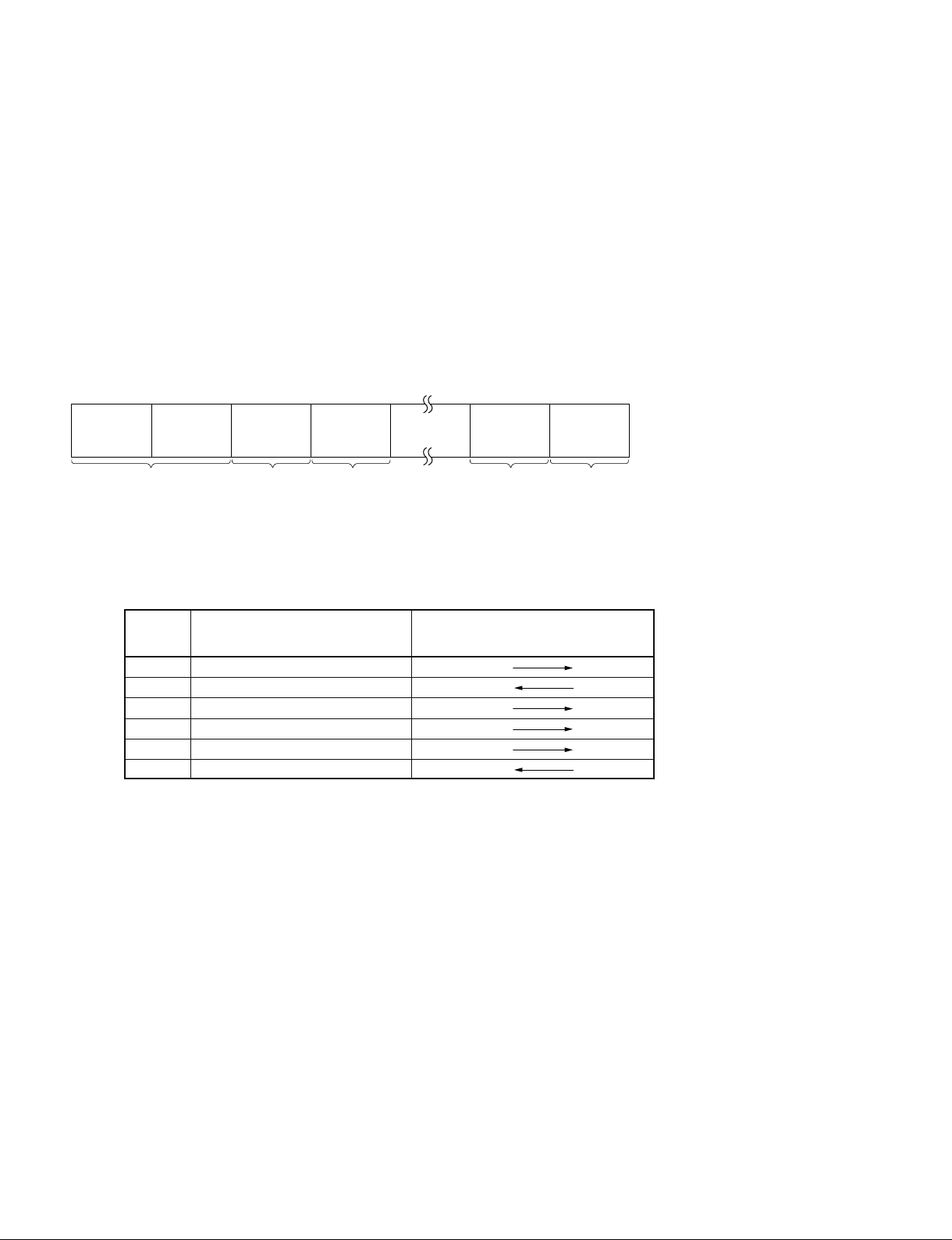
3. Command Block Format (CMD Block)
3-1. VTP Command
The communication between the CONTROLLER and the DEVICE is composed of CMD-1 + DATA
COUNT, CMD-2 + DATA and CHECKSUM, and is transmitted from CMD-1 + DATA COUNT in
order.
When the DATA COUNT is zero, the DATA is not transmitted.
When it is not zero, the DATA corresponded with the value is inserted between CMD-2 and CHECKSUM.
The command block can be illustrated as shown.
MSD LSD
CMD-1 CMD-2 DATA-1 CHECKSUM
DATA
COUNT
1 BYTE 1 BYTE 1 BYTE 1 BYTE 1 BYTE
DATA-n
(MAX.15)
CMD-1 : CMD-1 classifies the command into the main groups which indicates the function and direction
of the data words to follow.
Contents of CMD-1
CMD-1 Function
0 SYSTEM CONTROL
1 SYSTEM CONTROL RETURN
2 TRANSPORT CONTROL
4 PRESET & SELECT CONTROL
6 SENSE REQUEST
7 SENSE RETURN
Controller Device
Direction
DATA COUNT : DATA COUNT indicates the number of data bytes that are added to the
command. (0 to FH)
CMD-2 : Specifies the respective commands.
DATA : The number of data bytes and their contents are defined by the respective
commands.
CHECKSUM : The CHECKSUM is the lower eight value of the sum of the data bytes from
the first byte to the last byte immediately before CHECKSUM. It is used to
check the errors that are incurred by the data communication.
2
DSR Series
Page 7
0x31
^^^^
CMD1 CMD20xFF
BYTE1 BYTE254
CSDATA
BYTE0
......
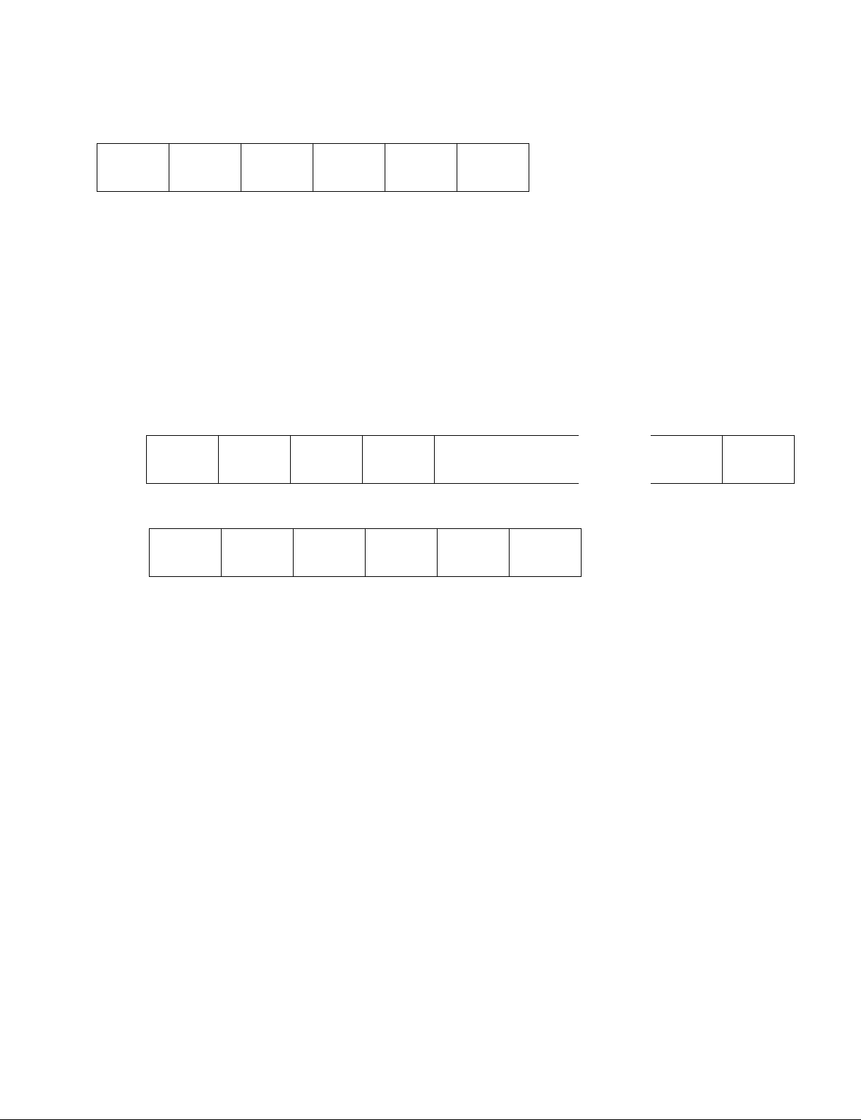
3-2. DSR-DR1000/A DISK Command
ID CMD1 CMD2DC CSDATA
1byte 1byte 1byte 1byte 0 to 255byte 1byte
a. ID : Code undefined as CMD1 of Sony VTR 9PIN PROTOCOL.
0x30 and 0x31 are designated as an ID of the extension command for DISK.
ID:0x30 : Indicates that it is a single block with less than 256-byte DATA length. Or it indicates
that it is the last block when transmitting a command by dividing into multiple blocks.
ID:0x31 : Indicates that there is a continuous block when transmitting a command by dividing it
into multiple blocks.
Example: When transmitting a command with data consisting of 256-byte DATA length
First block
Second block
0x30
^^^^
CMD1 CMD20xFF CSDATA
b. DC : Number of bytes of DATA (0 to 255)
BYTE255
DSR Series
3
Page 8

c. CMD1: Specifies the categories of commands.
Contents of CMD-1
CMD1 FUNCTION DIRECTION
0x00 VTR SYSTEM CONTROL T → R
0x01 VTR SYSTEM CONTROL RETURN T ← R
0x02 VTR TRANSPORT CONTROL T → R
0x04 VTR PRESET & SELECT CONTROL T → R
0x06 VTR SENSE REQUEST T → R
0x07 VTR SENSE RETURN T ← R
0x10 SYSTEM PRESET T → R
0x11 SYSTEM STATUS SENSE T → R
0x12 SYSTEM STATUS T ← R
0x13 DRIVE CONTROL/PRESET T → R
0x14 DRIVE STATUS SENSE T → R
0x15 DRIVE STATUS T ← R
0x16 PORT CONTROL/PRESET T → R
0x17 PORT STATUS SENSE T → R
0x18 PORT STATUS T ← R
0x19 FILE CONTROL/PRESET T → R
0x1A FILE STATUS SENSE T → R
0x1B FILE STATUS T ← R
0xFx DEVICE DEPENDENT COMMAND T → R
T ← R
T:CONTROLLING DEVICE
R:CONTROLLED DEVICE
4
DSR Series
Page 9

[System related commands]
0x00 to 0x07 are the ones that the upper four bits of CMD1 of the Sony VTR 9PIN PROTOCOL is
shifted to four bits rightward. The content is the same as that of the Sony VTR 9PIN PROTOCOL.
0x10 to 0x12 are in a category related to parameter settings and requests unique to the device.
[Drive related commands]
0x13 to 0x15 are in a category related to controls or parameter settings and requests for the DISK DEVICE that the device has. Drive ID is added to all the commands in the category, and the drive ID
specifies a target DISK DEVICE.
[Port related commands]
0x16 to 0x18 are in a category related to controls or parameter settings and requests for the logical port
that the device has. Port ID is added to all the commands in the category, and the port ID specifies a
target port.
[File related commands]
0x19 to 0x1B are in a category related to controls or parameter settings and requests for the opened file.
File handle is added to all the commands in this category, and the file handle specifies a target file.
[Device dependent commands]
0xFx (0xF0 to 0xFF) is in a category that allows defining the commands that depends on the device.
However, some commands do not fall into these categories.
DSR Series
5
Page 10

d. CMD2 : Assigns individual commands according to the following code category list.
. CMD2 code category list
CMD2 (0x00 to 0xFF)
|
+----- Operation related codes (0x00 to 0x7F)
| |
| +-----Basic operation, open operation (0x00 to 0x3F)
| |
| +-----AUTO/MACRO operation (0x40 to 0x5F)
| |
| +-----Machine, maintenance, and service related codes (0x60 to 0x6F)
| |
| +-----Other, special operation (0x70 to 0x7F)
+----- Preset related codes (0x80 to 0xFF)
|
+-----FILE related codes (0x80 to 0x8F)
|
+-----AUTO/MACRO MODE setting (0x90 to 0x9F)
|
+-----VIDEO related codes (0xA0 to 0xAF)
|
+-----AUDIO related codes (0xB0 to 0xBF)
|
+-----TC related codes (0xC0 to 0xCF)
|
+----- System parameter setting (0xD0 to 0xDF)
|
+----- Maintenance and service related codes (0xE0 to 0xEF)
|
+-----Other, special mode setting (0xF0 to 0xFF)
Individual codes are categorized as follows according to whether they are odd and even:
However, some codes do not fall into these categories depending on the content of commands.
Even (LSB=0) **** OFF, playback Odd (LSB=1) **** ON, recording
e. DATA : Additional data of individual commands (total of 255 bytes at maximum).
f. CS (CHECKSUM) : CS is the lower eight value of the sum of the data bytes from the first byte (ID) to
the last byte immediately before CS.
6
DSR Series
Page 11
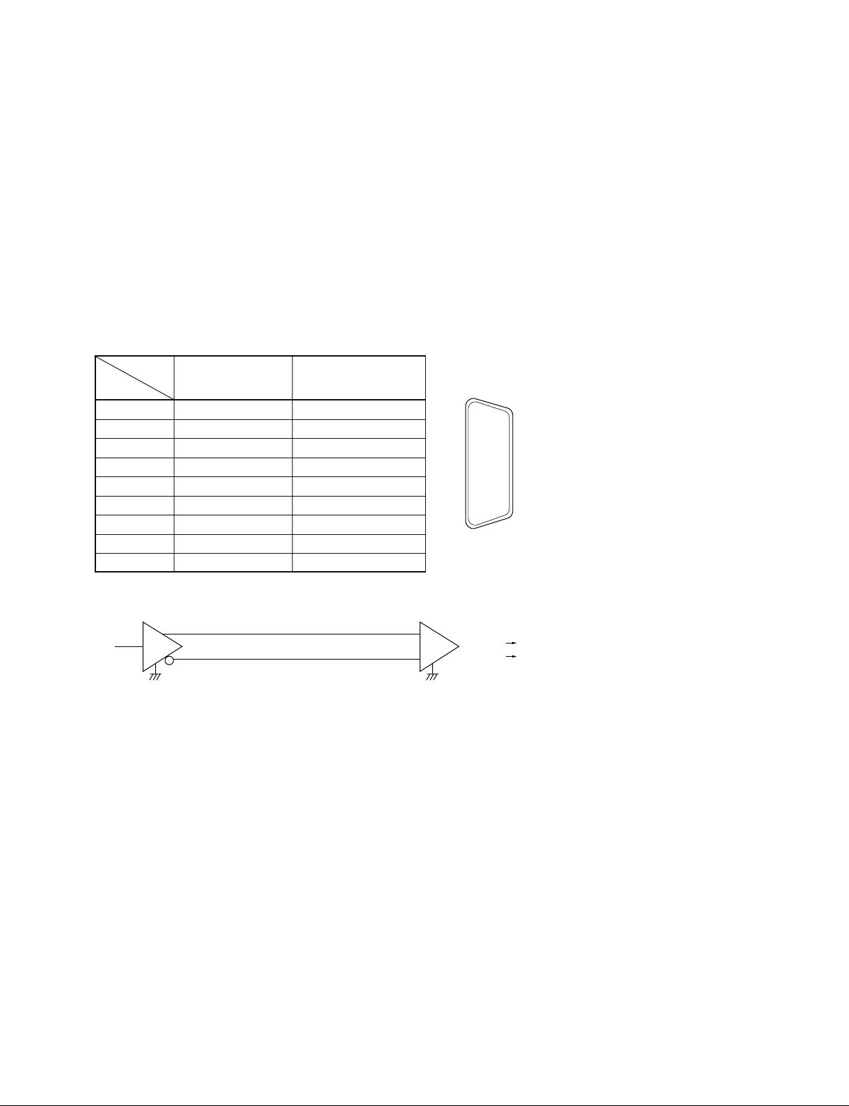
4. Connector Pin Assignment
Interface connector : 9 pin D-subminiature female (D-9S)
The pin assignment for the CONTROLLER and the DEVICE is as shown in the following table.
Among the DSR series VTRs, the VTRs (DSR-85/85P) that have the built-in CONTROLLER function,
obtain the following CONTROLLER pin assignment when they execute the QSDI dubbing and also
when the RECORDER lamp or the PLAYER lamp turns on the control panel.
Except for that, it’s become pin assignment of DEVICE.
The VTR not had the function as CONTROLLER (DSR-60/60P) is always become pin assignment of
DEVICE.
Signal
Pin
1 Frame Ground Frame Ground
2 Receive A Transmit A
3 Transmit B Receive B
4 Transmit Common Receive Common
5 Spare Spare
6 Receive Common Transmit Common
7 Receive B Transmit B
8 Transmit A Receive A
9 Frame Ground Frame Ground
Controller Device
A and B are defined as shown below.
B
T R
T : Transmit R : Receive
A
+
_
1
6
2
7
3
8
4
9
5
External view
A < B “1” (MARK)
A > B “0” (SPACE)
DSR Series
7
Page 12

5. Communication Protocol
1) All communication between the CONTROLLER and the DEVICE will be under the direct supervision of the CONTROLLER.
When the DEVICE receives the COMMAND sent from CONTROLLER, the following COMMAND
is returned.
. In the case that the DEVICE receives the COMMAND not required the data
..................... ACK
. In the case that the DEVICE receives the COMMAND required the data
..................... COMMAND + DATA
. In the case that the error communication is detected or the undefined COMMAND is received
..................... NAK + ERROR DATA
2) The CONTROLLER is not transmit additional COMMAND blocks to a DEVICE prior to receivers
an appropriate response to a previous COMMAND block.
3) The CONTROLLER is not interrupt transmission of a byte in a COMMAND block for more than 10
ms. A DEVICE detecting an interruption of a byte in a COMMAND block that exceeds 10 ms.
CONTROLLER execute a TIME-OUT error sequence.
A DEVICE will void the receiving COMMAND block and transmit a NAK (TIME OUT).
4) The DEVICE, following receipt of a COMMAND block from the CONTROLLER will transmit a
response within 9 ms.
Therefore if the CONTROLLER cannot receive the appropriate response from the DEVICE within
10 ms. After performing the COMMAND block transmission, it will execute as the communication
is not performed under the normal condition, and it will process as necessary.
5) The DEVICE, upon detection of an error, it will immediately transmit a NAK to the CONTROLLER.
(The contents of an error is shown on the COMMAND tables.)
The CONTROLLER, upon receipt of NAK, it will immediately stop transmission of the COMMAND block. The DEVICE, following transmission of NAK, it will receive a subsequent COMMAND block within 10 ms. (except NAK UNDEFINED COMMAND) and will process as necessary.
8
DSR Series
Page 13

6. Command
The marks shown in the tables mean the following contents.
1) O marked COMMAND’s model can correspond. If the contents are in the RETURN column,
RETURN + DATA will be returned.
If the contents are not in the RETURN column, “10.01 : ACK” will be returned.
2) T marked COMMAND returns ACK as RETURN, but does not operate.
3) X marked COMMAND does not correspond and returns “11.12.01 : NAK UNDEFINED
COMMAND.
4) For details of the commands for disk recorders such as DSR-DR1000/A, refer to Section 6-2. Command Table (for Disk Recorder).
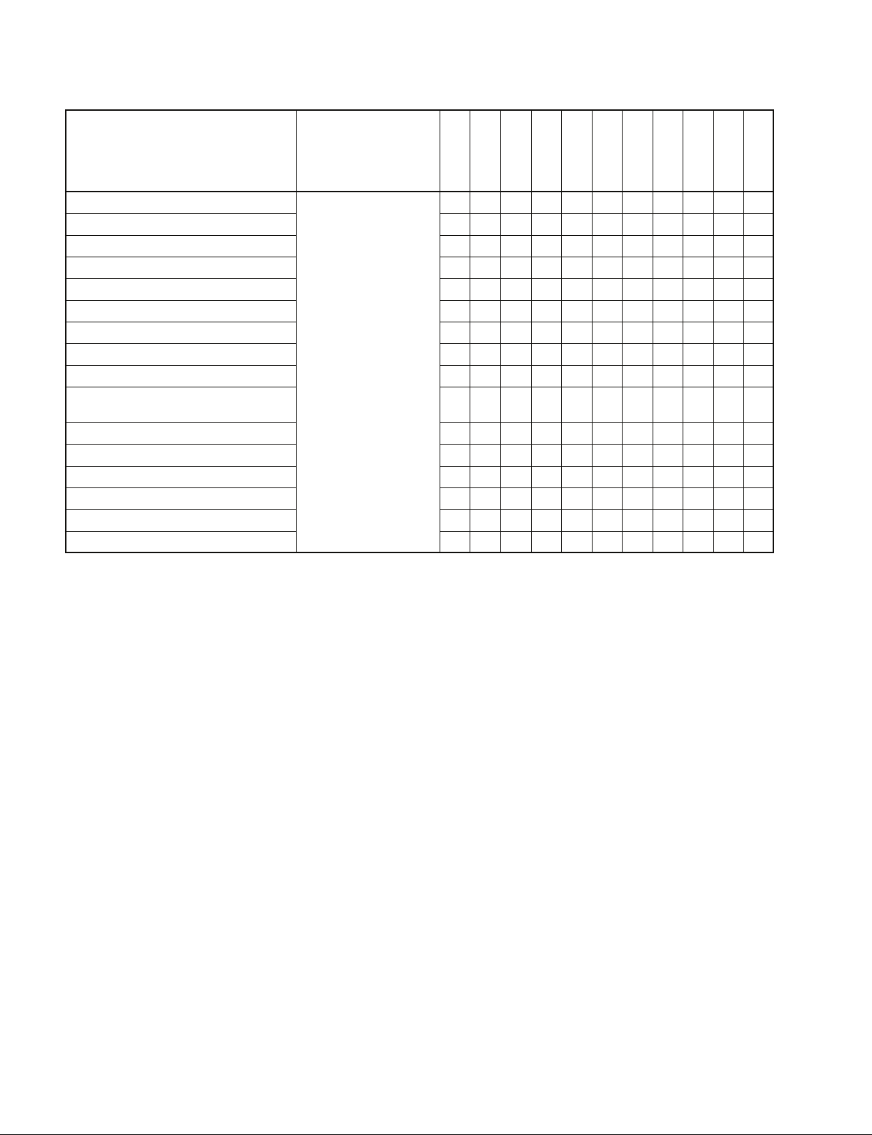
6-1. Command Table (for Cassette Recorder/Player)
Command
00.0C : LOCAL DISABLE
00.11 : DEVICE TYPE REQUEST
00.1D : LOCAL ENABLE
20.00 : STOP
20.01 : PLAY
20.02 : REC
20.04 : STANDBY OFF
20.05 : STANDBY ON
20.0D : DMC START
20.0F : EJECT
20.10 : FAST FWD
2X.11 : JOG FWD
2X.12 : VAR FWD
2X.13 : SHUTTLE FWD
20.20 : REWIND
2X.21 : JOG REV
2X.22 : VAR REV
2X.23 : SHUTTLE REV
20.30 : PREROLL
24.31 : CUE UP WITH DATA
24.32 : SYNC POINT PREROLL
24.34 : SYNC PLAY
21.38 : PROGRAM PLAY +
21.39 : PROGRAM PLAY _
20.3C : DMC PREROLL
20.40 : PREVIEW
20.41 : REVIEW
Return
O → ACK
X → NAK
12.11 : DEVICE TYPE
O → ACK
X → NAK
O/T → ACK
X → NAK
HVR-1500/A
(DVCAM)
HVR-1500
(HDV)
HVR-1500A
(HDV)
DSR-2000/A
DSR-1800/A
DSR-1600/A
DSR-1500/A
DSR-85/80
DSR-70A
DSR-70
DSR-60
OOOOOOOOOOO
OOOOOOOOOOO
OOOOOOOOOOO
OOOOOOOOOOO
OOOOOOOOOOO
OOOOOTOOOOT
OOOOOOOOOOO
OOOOOOOOOOO
XXXOXXXXOXX
OOOOOOOOOOO
OOOOOOOOOOO
OOOOOOOOOOO
OOOOOOOOOOO
OOOOOOOOOOO
OOOOOOOOOOO
OOOOOOOOOOO
OOOOOOOOOOO
OOOOOOOOOOO
OOOOOOOOOOO
OOOOOOOOOOO
OOOOOOOOOOO
OOOOOOOOOOO
XXXOXXXXOXX
XXXOXXXXOXX
XXXOXXXXOXX
OTTOOTOOOOT
OTTOOTOOOOT
DSR Series
9
Page 14
Command
20.42 : AUTO EDIT
20.4B : DMC RUN
20.4C : DMC PREVIEW
20.52 : TENSION RELEASE
20.54 :
ANTI-CLOG TIMER DISABLE
20.55 : ANTI-CLOG TIMER ENABLE
2X.5C: DMC SET FWD
2X.5D: DMC SET REV
20.60 : FULL EE OFF
20.61 : FULL EE ON
20.63 : SELECT EE ON
20.64 : EDIT OFF
20.65 : EDIT ON
Return
O/T → ACK
X → NAK
HVR-1500/A
(DVCAM)
HVR-1500
(HDV)
HVR-1500A
(HDV)
DSR-2000/A
DSR-1800/A
DSR-1600/A
DSR-1500/A
DSR-85/80
DSR-70A
DSR-70
DSR-60
OTTOOTOOOOT
XXXOXXXXOXX
XXXOXXXXOXX
OOOOOOOOOOO
OOOOOOOOOOO
OOOOOOOOOOO
XXXOXXXXOXX
XXXOXXXXOXX
OOOOOTOOOOT
OOOOOTOOOOT
OTTOOTOOOOT
OTTOOTOOOOT
OTTOOTOOOOT
10
DSR Series
Page 15

Command
44.00 : TIMER-1 PRESET
44.04 : TIME CODE PRESET
4X.05 : USER’S BIT PRESET
40.08 : TIMER-1 RESET
40.10 : IN ENTRY
40.11 : OUT ENTRY
40.12 : A IN ENTRY
40.13 : A OUT ENTRY
44.14 : IN DATA PRESET
44.15 : OUT DATA PRESET
44.16 : A IN DATA PRESET
44.17 : A OUT DATA PRESET
40.18 : IN SHIFT +
40.19 : IN SHIFT _
40.1A : OUT SHIFT +
40.1B : OUT SHIFT _
40.1C : A IN SHIFT +
40.1D : A IN SHIFT _
40.1E : A OUT SHIFT +
40.1F : A OUT SHIFT _
40.20 : IN RESET
40.21 : OUT RESET
40.22 : A IN RESET
40.23 : A OUT RESET
40.24 : IN RECALL
40.25 : OUT RECALL
40.26 : A IN RECALL
40.27 : A OUT RECALL
40.2D : LOST LOCK RESET
4X.30 : EDIT PRESET
44.31 : PREROLL TIME PRESET
41.32 : TAPE/AUTO SELECT
41.36 : TIMER MODE SELECT
41.37 : INPUT CHECK
41.3D : PREREAD MODE SELECT
43.3F : Δ t REC/PLAY PRESET
40.40 : AUTO MODE OFF
40.41 : AUTO MODE ON
40.44 : AUDIO SPLIT OFF
40.45 : AUDIO SPLIT ON
Return
O/T → ACK
X → NAK
HVR-1500/A
(DVCAM)
HVR-1500
(HDV)
HVR-1500A
(HDV)
DSR-2000/A
DSR-1800/A
DSR-1600/A
DSR-1500/A
DSR-85/80
DSR-70A
DSR-70
DSR-60
OOOOOOOOOOO
OOOOOTOOOOT
OOOOOTOOOOT
OOOOOOOOOOO
OOOOOOOOOOO
OOOOOOOOOOO
OOOOOOOOOOO
OOOOOOOOOOO
OOOOOOOOOOO
OOOOOOOOOOO
OOOOOOOOOOO
OOOOOOOOOOO
OOOOOOOOOOO
OOOOOOOOOOO
OOOOOOOOOOO
OOOOOOOOOOO
OOOOOOOOOOO
OOOOOOOOOOO
OOOOOOOOOOO
OOOOOOOOOOO
OOOOOOOOOOO
OOOOOOOOOOO
OOOOOOOOOOO
OOOOOOOOOOO
OOOOOOOOOOO
OOOOOOOOOOO
OOOOOOOOOOO
OOOOOOOOOOO
OOOOOOOOOOO
OTTOOTOOOOT
OOOOOOOOOOO
OOOOOTOOOOT
OOOOOOOOOOO
OOOOOTOOOOT
XXXOXXXXOXX
TTTTTTT
OOOOOOOOOOO
OOOOOOOOOOO
OTTOOOOOOOO
OTTOOOOOOOO
85 : O
OTT
80 : T
DSR Series
11
Page 16
Command
40.46 : VARIABLE MEMORY OFF
40.47 : VARIABLE MEMORY ON
42.50 : DA INPUT SELECT
4X.54 : EXTENDED DA INPUT SELECT
41.58 : DA SAMPLING FREQ PRESET
41.60 : VITC BYPASS
42.61 : TCG MODE SELECT
42.70 : VIDEO INPUT SELECT
41.9E : SUPERIMPOSE
4X.AE: AUDIO MONITOR CHANNEL
SELECT
40.C0 : TIMELINE STOP
40.C1 : TIMELINE RUN
44.C3 : TIMELINE PRESET
4X.C4: DEFINE EVENT
42.C5 : CLEAR EVENT
41.CB : BREAK
Return
O/T → ACK
X → NAK
HVR-1500/A
(DVCAM)
HVR-1500
(HDV)
HVR-1500A
(HDV)
DSR-2000/A
DSR-1800/A
DSR-1600/A
DSR-1500/A
DSR-85/80
DSR-70A
DSR-70
DSR-60
XXXOXXXXTXX
XXXOXXXXTXX
OOOOOTOOOOT
OOOOOTOOOOT
OTTOOTOOOOT
OTTOOTOXOXX
OOOOOTOOOOT
OOTOOTOOOOT
OOOOOOOOOOO
OOOOOOOXOXX
OOOOOOOOOOO
OOOOOOOOOOO
OOOOOOOOOOO
OOOOOOOOOOO
OOOOOOOOOOO
OOOOOOOOOOO
12
DSR Series
Page 17
Command
61.0A : TC GEN DATA
SENSE
61.0C : CURRENT TIME
SENSE
60.10 : IN DATA SENSE
60.11 : OUT DATA SENSE
60.12 : A IN DATA SENSE
60.13 : A OUT DATA SENSE
60.20 : STATUS SENSE
60.2E : COMMAND SPEED
SENSE
60.2F : VAR MEM SPEED
SENSE
6X.30 : EDIT PRESET SENSE
60.31 : PREROLL TIME
SENSE
60.32 : TAPE/AUTO SENSE
60.36 : TIMER MODE SENSE
60.3F : Δ t REC/PLAY
PRESET SENSE
60.50 : DA INPUT SENSE
6X.54 : EXTENDED DA INPUT
SENSE
60.58 : DA SAMPLING FREQ
SENSE
60.60 : VITC BYPASS SENSE
60.61 : TCG MODE SENSE
Return
74.08 : GEN TIME DATA
74.09 : GEN UB DATA
78.08 : GEN TC & UB DATA
74.00 : TIMER-1 DATA
74.01 : TIMER-2 DATA
74.04 : LTC TIME DATA
78.04 : LTC TIME & UB DATA
74.05 : LTC UB DATA
74.06 : VITC TIME DATA
78.06 :
74.07 : VITC UB DATA
74.14 : LTC INTERPOLATED
78.14 : LTC INTERPOLATED
74.16 :
78.16 : VITC HOLD TIME &
70.0D : REQUEST TIME
74.10 : IN DATA
74.11 : OUT DATA
74.12 : A IN DATA
74.13 : A OUT DATA
7X.20 : STATUS DATA
71.2E : COMMAND SPEED
71.2F : VAR MEM SPEED
7X.30 : EDIT PRESET DATA
74.31 : PREROLL TIME
71.32 : TAPE/AUTO STATUS
71.36 : TIMER MODE DATA
73.3F : Δ t REC/PLAY\
71.50 : DA INPUT STATUS
7X.54 : EXTENDED DA
71.58 : DA SAMPLING FREQ
71.60 :
72.61 : TCG MODE
VITC TIME & UB DATA
TIME DATA
TIME & UB DATA
VITC HOLD TIME DATA
UB DATA
DATA MISSING
DATA
DATA
DATA
DATA
PRESET DATA
INPUT STATUS
STATUS
VITC BYPASS STATUS
HVR-1500/A
(DVCAM)
HVR-1500
(HDV)
HVR-1500A
(HDV)
DSR-2000/A
DSR-1800/A
DSR-1600/A
DSR-1500/A
DSR-85/80
DSR-70A
DSR-70
DSR-60
OOOOOXOOOOX
OOOOOXOOOOX
OOOOOXOOOOX
OOOOOOOOOOO
OOOOOOOOOOO
OOOOOOOOOOO
OOOOOOOOOOO
OOOOOOOOOOO
OXXOOOOXOXX
OXXOOOOXOXX
OXXOOOOXOXX
OOOOOOOOOOO
OOOOOOOOOOO
OXXOOOOXOXX
OXXOOOOXOXX
OOOOOOOOOOO
OOOOOOOOOOO
OOOOOOOOOOO
OOOOOOOOOOO
OOOOOOOOOOO
OOOOOOOOOOO
OOOOOOOOOOO
XXXOXXXXOXX
OOOOOOOOOOO
OOOOOOOOOOO
OOOOOOOOOOO
OOOOOOOOOOO
OOOOOOOOOOO
OOOOOXOOOOX
OOOOOXOOOOX
OOOOOXOOOOX
OOOOOOOXOXX
OOOOOXOOOOX
DSR Series
13
Page 18
Command
60.70 : VIDEO INPUT SENSE
60.9E : SUPERIMPOSE
SENSE
60.AE : AUDIO MONITOR
60.C2 :
TIMELINE SOURCE
SENSE
60.C3 : TIMELINE TIME
SENSE
62.C4 : EVENT DATA SENSE
60.C6 :
TIMELINE STATUS
SENSE
61.C7 : EVENT QUEUE
SENSE
61.C8 : UNSUCCESSFUL
EVENT SENSE
Return
72.70 :
71.9E : SUPERIMPOSE
74.AE : AUDIO MONITOR
71.C2 : TIMELINE SOURCE
75.C3 : TIMELINE TIME
7X.C4 : EVENT DATA
75.C6 : TIMELINE STATUS
7X.C7 : EVENT QUEUE
7X.C8 : UNSUCCESSFUL
VIDEO INPUT STATUS
STATUS
CHANNEL STATUS
EVENT
HVR-1500/A
(DVCAM)
HVR-1500
(HDV)
HVR-1500A
(HDV)
DSR-2000/A
DSR-1800/A
DSR-1600/A
DSR-1500/A
DSR-85/80
DSR-70A
DSR-70
DSR-60
OOOOOXOOOOX
OOOOOOOOOOO
OOOOOOOXOXX
OOOOOOOOOOO
OOOOOOOOOOO
OOOOOOOOOOO
OOOOOOOOOOO
OOOOOOOOOOO
OOOOOOOOOOO
14
DSR Series
Page 19

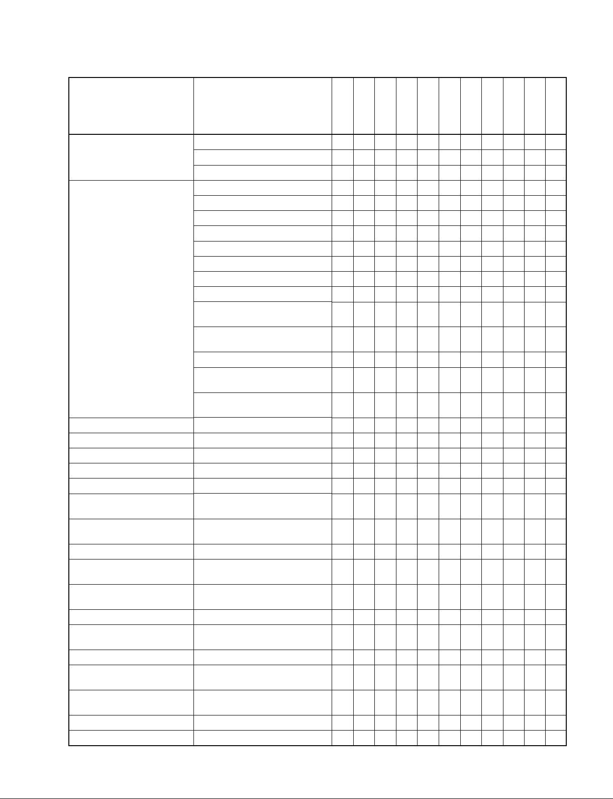
6-2. Command Table (for Disk Recorder)
“IN (R)” of DSR-DR1000/A indicates the RECORDER side during the simultaneous record/playback
(REMOTE I/F of INTERFACE SELECT is set to “9PIN (DUAL))”.
In the same way, “OUT (P)” of DSR-DR1000/A indicates the PLAYER side.
n
The IN points and the OUT points of the program playback that are set using the “← (IN)” or “→ (OUT)” of the
front panel are different from the IN points and the OUT points that are set from the 9-pin remote control unit.
When the IN DATA SENSE command and the OUT DATA SENSE command that are issued from the 9-pin
remote control unit are sent to the DSR-DR1000/A, the IN points and the OUT points that are by this operation will not be returned.
Command
00.0C : LOCAL DISABLE
00.11 : DEVICE TYPE REQUEST
00.1D : LOCAL ENABLE
20.00 : STOP
20.01 : PLAY
20.02 : REC
20.04 : STANDBY OFF
20.05 : STANDBY ON
20.0D : DMC START
20.0F : EJECT
20.10 : FAST FWD
2X.11 : JOG FWD
2X.12 : VAR FWD
2X.13 : SHUTTLE FWD
20.20 : REWIND
2X.21 : JOG REV
2X.22 : VAR REV
2X.23 : SHUTTLE REV
20.30 : PREROLL
24.31 : CUE UP WITH DATA
24.32 : SYNC POINT PREROLL
24.34 : SYNC PLAY
21.38 : PROGRAM PLAY +
21.39 : PROGRAM PLAY _
20.3C : DMC PREROLL
20.40 : PREVIEW
20.41 : REVIEW
20.42 : AUTO EDIT
20.4B : DMC RUN
20.4C : DMC PREVIEW
20.52 : TENSION RELEASE
20.54 :
ANTI-CLOG TIMER DISABLE
*1 : Both of the RECORDER and the PLAYER side can be set to Disable independently.
DSR Series
O → ACK
X → NAK
12.11 : DEVICE TYPE
O → ACK
X → NAK
O/T → ACK
X → NAK
Return
DSR-DR1000/A DSR-DR1000/A DSR-DR1000/A
IN (R) OUT (P)
OO*1O
OOO
OOO
OOO
OTO
OOT
OOO
OOO
OTO
TTT
OTO
OTO
OTO
OTO
OTO
OTO
OTO
OTO
OTO
OTO
OTO
OTO
OTO
OTO
OTO
TTT
TTT
TTT
OTO
OTO
OOO
TTT
*1
15
Page 20
Command
Return
DSR-DR1000/A DSR-DR1000/A DSR-DR1000/A
IN (R) OUT (P)
20.55 : ANTI-CLOG TIMER ENABLE
2X.5C: DMC SET FWD
2X.5D: DMC SET REV
20.60 : FULL EE OFF
20.61 : FULL EE ON
O/T → ACK
X → NAK
20.63 : SELECT EE ON
20.64 : EDIT OFF
20.65 : EDIT ON
*2 : When both of the R and P indicators of the LINE OUT SELECT on the front panel light, output can be selected from the (P) side port.
TTT
OTO
OTO
OTO
OTO
TTO
TTT
TTT
*2
*2
*2
16
DSR Series
Page 21
Command
44.00 : TIMER-1 PRESET
44.04 : TIME CODE PRESET
4X.05 : USER’S BIT PRESET
40.08 : TIMER-1 RESET
40.10 : IN ENTRY
40.11 : OUT ENTRY
40.12 : A IN ENTRY
40.13 : A OUT ENTRY
44.14 : IN DATA PRESET
44.15 : OUT DATA PRESET
44.16 : A IN DATA PRESET
44.17 : A OUT DATA PRESET
40.18 : IN SHIFT +
40.19 : IN SHIFT _
40.1A : OUT SHIFT +
40.1B : OUT SHIFT _
40.1C : A IN SHIFT +
40.1D : A IN SHIFT _
40.1E : A OUT SHIFT +
40.1F : A OUT SHIFT _
40.20 : IN RESET
40.21 : OUT RESET
40.22 : A IN RESET
40.23 : A OUT RESET
40.24 : IN RECALL
40.25 : OUT RECALL
40.26 : A IN RECALL
40.27 : A OUT RECALL
40.2D : LOST LOCK RESET
4X.30 : EDIT PRESET
44.31 : PREROLL TIME PRESET
41.32 : TAPE/AUTO SELECT
41.33 : SERVO REFERENCE SELECT
41.36 : TIMER MODE SELECT
41.37 : INPUT CHECK
41.3D : PREREAD MODE SELECT
43.3F : Δ t REC/PLAY PRESET
40.40 : AUTO MODE OFF
40.41 : AUTO MODE ON
40.44 : AUDIO SPLIT OFF
Return
O/T → ACK
X → NAK
DSR-DR1000/A DSR-DR1000/A DSR-DR1000/A
IN (R) OUT (P)
OO*3O
*3
OOT
OOT
OO*3O
OO*4O
OO*4O
OO*4O
OO*4O
OO*4O
OO*4O
OO*4O
OO*4O
OO*4O
OO*4O
OO*4O
OO*4O
OO*4O
OO*4O
OO*4O
OO*4O
OO*4O
OO*4O
OO*4O
OO*4O
OO*4O
OO*4O
OO*4O
OO*4O
*3
*4
*4
*4
*4
*4
*4
*4
*4
*4
*4
*4
*4
*4
*4
*4
*4
*4
*4
*4
*4
*4
*4
*4
*4
OOO
TTT
OO*3O
*3
OOO
TTT
OOO
OT*5T
*5
XXX
TTT
OOO
OOO
OOO
*3 : The (R) side and the (P) side can be set to PRESET independently.
*4 : The (P) side can be set to the same setting as in the ordinary VTR. It jumps to these points at the event of Preroll.
The (R) side can only save the set data, and cannot perform the Preroll operation. It returns the set data to SENSE.
*5 : When both of the R and P indicators of the LINE OUT SELECT on the front panel light, the forced EE mode can be set from the (P) side.
DSR Series
17
Page 22
Command
40.45 : AUDIO SPLIT ON
40.46 : VARIABLE MEMORY OFF
40.47 : VARIABLE MEMORY ON
42.50 : DA INPUT SELECT
4X.54 : EXTENDED DA INPUT SELECT
41.58 : DA SAMPLING FREQ PRESET
41.60 : VITC BYPASS
42.61 : TCG MODE SELECT
42.70 : VIDEO INPUT SELECT
41.9E : SUPERIMPOSE
4X.AE: AUDIO MONITOR CHANNEL
SELECT
40.C0 : TIMELINE STOP
40.C1 : TIMELINE RUN
44.C3 : TIMELINE PRESET
4X.C4: DEFINE EVENT
42.C5 : CLEAR EVENT
41.CB : BREAK
Return
O/T → ACK
X → NAK
DSR-DR1000/A DSR-DR1000/A DSR-DR1000/A
IN (R) OUT (P)
OOO
OTT
OTT
OOO
OOO
OOO
OOO
OOO
OOO
OOO
OOO
OOO
OOO
OOO
OOO
OOO
OOO
18
DSR Series
Page 23
Command
61.0A : TC GEN DATA
SENSE
61.0C : CURRENT TIME
SENSE
60.10 : IN DATA SENSE
60.11 : OUT DATA SENSE
60.12 : A IN DATA SENSE
60.13 : A OUT DATA SENSE
60.20 : STATUS SENSE
60.2E : COMMAND SPEED
SENSE
60.2F : VAR MEM SPEED
SENSE
6X.30 : EDIT PRESET SENSE
60.31 : PREROLL TIME
SENSE
60.32 : TAPE/AUTO SENSE
60.36 : TIMER MODE SENSE
60.3F : Δ t REC/PLAY
PRESET SENSE
60.50 : DA INPUT SENSE
6X.54 : EXTENDED DA INPUT
SENSE
60.58 : DA SAMPLING FREQ
SENSE
60.60 : VITC BYPASS SENSE
60.61 : TCG MODE SENSE
Return
74.08 : GEN TIME DATA
74.09 : GEN UB DATA
78.08 : GEN TC & UB DATA
74.00 : TIMER-1 DATA
74.01 : TIMER-2 DATA
74.04 : LTC TIME DATA
78.04 : LTC TIME & UB DATA
74.05 : LTC UB DATA
74.06 : VITC TIME DATA
78.06 :
VITC TIME & UB DATA
74.07 : VITC UB DATA
74.14 : LTC INTERPOLATED
TIME DATA
78.14 : LTC INTERPOLATED
TIME & UB DATA
74.16 :
VITC HOLD TIME DATA
78.16 : VITC HOLD TIME &
UB DATA
70.0D : REQUEST TIME
DATA MISSING
74.10 : IN DATA
74.11 : OUT DATA
74.12 : A IN DATA
74.13 : A OUT DATA
7X.20 : STATUS DATA
71.2E : COMMAND SPEED
DATA
71.2F : VAR MEM SPEED
DATA
7X.30 : EDIT PRESET DATA
74.31 : PREROLL TIME
DATA
71.32 : TAPE/AUTO STATUS
DATA
71.36 : TIMER MODE DATA
73.3F : Δ t REC/PLAY\
PRESET DATA
71.50 : DA INPUT STATUS
7X.54 : EXTENDED DA
INPUT STATUS
71.58 : DA SAMPLING FREQ
STATUS
71.60 :
VITC BYPASS STATUS
72.61 : TCG MODE
DSR-DR1000/A DSR-DR1000/A DSR-DR1000/A
IN (R) OUT (P)
OOO
OOO
OOO
OO*6O
OO*6O
OO*6O
OO*6O
OO*6O
OO*6O
OO*6O
OO*6O
OO*6O
OO*6O
OO*6O
OO*6O
OO*6O
*6
*6
*6
*6
*6
*6
*6
*6
*6
*6
*6
*6
*6
OOO
OOO
OOO
OOO
OOO
OO*6O
*6
OOO
OOO
OOO
OOO
OOO
OOO
OOO
OOO
OOO
OOO
OOO
*6 : The respective values of the (R) side and the (P) side are returned respectively.
DSR Series
19
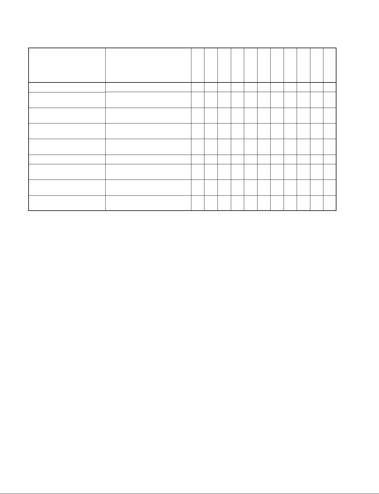
Page 24
Command
60.70 : VIDEO INPUT SENSE
60.9E : SUPERIMPOSE
SENSE
60.AE : AUDIO MONITOR
60.C2 :
TIMELINE SOURCE
SENSE
60.C3 : TIMELINE TIME
SENSE
62.C4 : EVENT DATA SENSE
60.C6 :
TIMELINE STATUS
SENSE
61.C7 : EVENT QUEUE
SENSE
61.C8 : UNSUCCESSFUL
EVENT SENSE
72.70 :
71.9E : SUPERIMPOSE
74.AE : AUDIO MONITOR
71.C2 : TIMELINE SOURCE
75.C3 : TIMELINE TIME
7X.C4 : EVENT DATA
75.C6 : TIMELINE STATUS
7X.C7 : EVENT QUEUE
7X.C8 : UNSUCCESSFUL
Return
VIDEO INPUT STATUS
STATUS
CHANNEL STATUS
EVENT
DSR-DR1000/A DSR-DR1000/A DSR-DR1000/A
OOO
OOO
OOO
OOO
OOO
OOO
OOO
OOO
OOO
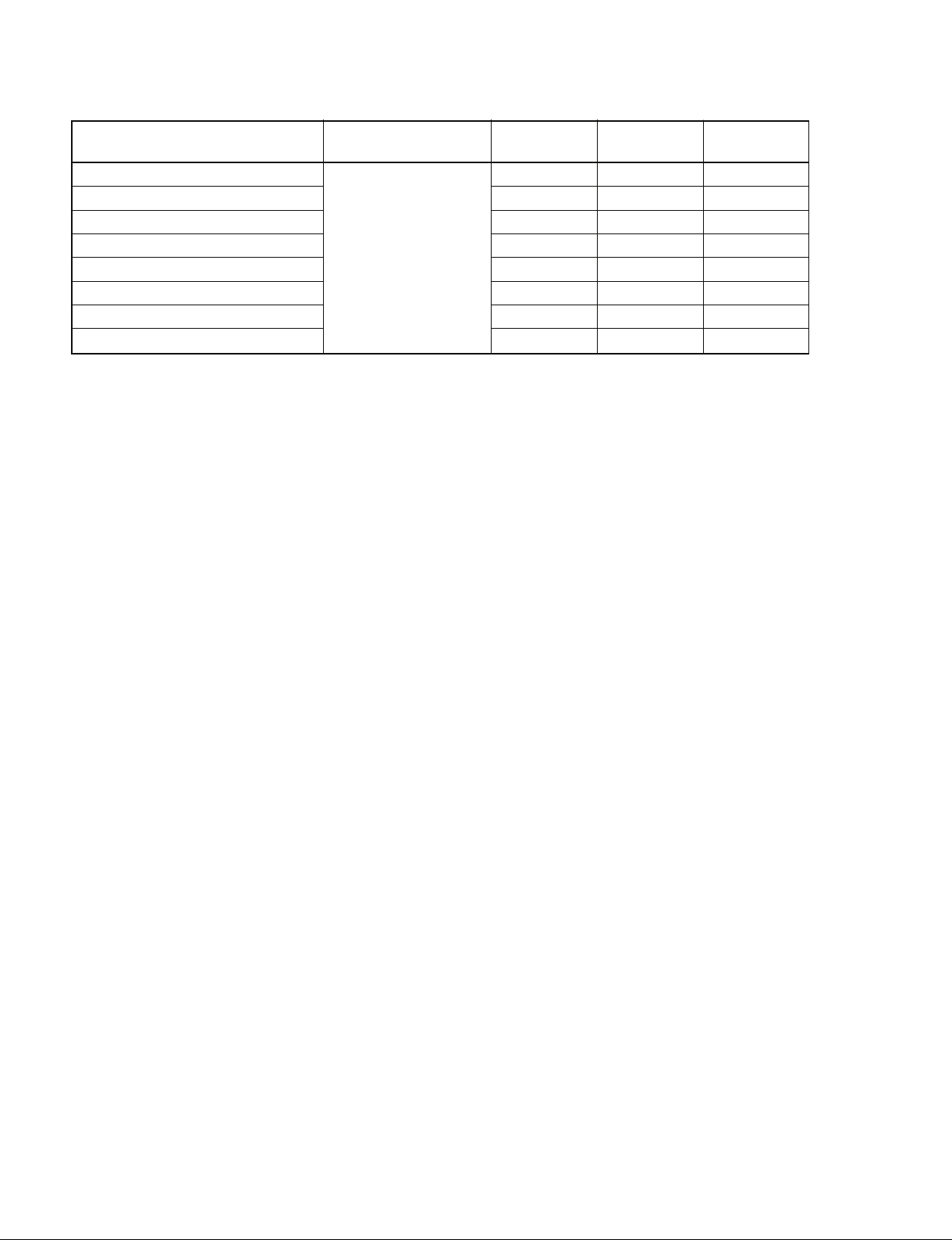
6-3. Command Table (for DSR-DR1000/A Disk Command)
COMMAND RETURN
DC C1 C2 D1
System Command
00 10 40
XX 10 41
00 10 42
00 10 43
04 11 D0
Drive Command
XX 13 03
0X 14 81
03 14 D0
Port Command
XX 16 00
01 17 00
File Command
01 19 01
03 1A 82
02 1A C0
VFL DOWNLOAD ENABLE
VFL DOWNLOAD DATA SET
VFL DOWNLOAD DATA WRITE
VFL DOWNLOAD DATA CLEAR
SYSTEM STATUS SENSE
DELETE
FILE SYSTEM DATA SENSE
DRIVE STATUS SENSE
OPEN PLAY
FILE OPEN STATUS SENSE
CLOSE
FILE ENTRY DATA SENSE
CURRENT TIME SENSE
IN (R) OUT (P)
DC C1 C2 D1
10 01
10 01
10 01
10 01
XX 12 D0
10 01
XX 15 81
XX 15 D0
10 01
0X 18 00
10 01
XX 1B 82
XX 1B C0
Both DSR-DR1000/A IN (R) and DSR-DR1000/A OUT (P) have the same function (receiving the same command).
20
DSR Series
Page 25

7. Protocol Command
7-1. VTR Command
00.0C : LOCAL DISABLE
When receiving this command, all functions of the DEVICE will be disabled.
00.11 : DEVICE TYPE REQUEST
12.11 : DEVICE TYPE
The “00.11 : DEVICE TYPE REQUEST” command is used to ask the model of the DEVICE to
be connected, and if the DEVICE receives this command, the “12.11 : DEVICE TYPE” with 2
bytes data will be sent back as a response.
Model DATA-1 DATA-2
DSR-2000/2000P/2000A/2000AP 8X 14
DSR-1800/1800P/1800A/1800AP 8X 15
DSR-1600/1600P/1600A/1600AP 8X 16
DSR-1500/1500P/1500A/1500AP 8X 17
DSR-DR1000/DR1000P/DR1000A/DR1000AP 8X 18
DSR-85/85P 8X 10
DSR-80/80P 8X 11
DSR-70A/70AP 8X 13
DSR-70/70P 8X 13
DSR-60/60P 8X 12
NTSC Model : X=0
PAL Model : X=1
00.1D : LOCAL ENABLE
When receiving this command, the control panel operation will be enabled according to the
DEVICE setting.
When the power of the DEVICE is turned on, it will be set to the LOCAL ENABLE state.
10.01 : ACK
When receiving this command, the DEVICE will send back this command as acknowledgement.
11.12 : NAK
When detecting the communication errors or receiving the undefined COMMAND, the
CONTROLLER will send back this command as not-acknowledgement.
BIT-7 to BIT-0 of DATA-1 will be set in accordance with the contents.
[DATA-1]
BIT-7 BIT-6 BIT-5 BIT-4 BIT-3 BIT-2 BIT-1 BIT-0
TIME OUT
FRAMING
ERROR
20.00 : STOP
20.01 : PLAY
20.02 : REC
20.04 : STANDBY OFF
20.05 : STANDBY ON
When receiving one of the above commands, the DEVICE will be in the specified mode.
The “20.04 : STANDBY OFF” command is available only when the DEVICE is in STOP mode.
OVERRUN
ERROR
PARITY
ERROR
CHECKSUM
ERROR
SOFTWARE
OVERRUN
UNDEFINED
COMMAND
DSR Series
21
Page 26

20.0D : DMC START : DMC=Dynamic Motion Control (=VAR MEMORY)
This command is used to run the DEVICE from the present tape position at the speed that is
stored by the “20.4B : DMC RUN” command.
20.0F : EJECT
When receiving this command, the DEVICE ejects the cassette.
20.10 : FAST FWD
20.20 : REWIND
When receiving this command, the DEVICE will become the specified mode.
2X.11 : JOG FWD
2X.12 : VAR FWD
2X.13 : SHUTTLE FWD
2X.21 : JOG REV
2X.22 : VAR REV
2X.23 : SHUTTLE REV
When receiving one of the above commands, the DEVICE will start running in accordance with
speed data defined by the DATA-1 and the DATA-2.
When only DATA-1 is given, (X=1) and the tape speed will be defined as follows.
TAPE SPEED=10
Example)
TAPE SPEED SPEED DATA
STILL 0 (0H)
0.1 times normal speed 32 (20H)
1.0 times normal speed 64 (40H)
About 2.9 times normal speed 79 (4FH)
When setting more precise value than the tape speed defined by DATA-1, DATA-2 will be
added, however, the precise value is a linear approximate value. (X=2)
When both DATA-1 and DATA-2 are given, the tape speed will be defined as follows.
TAPE SPEED=10
N : SPEED DATA OF DATA-1 (DECIMAL)
N’: SPEED DATA OF DATA-2 (DECIMAL)
20.30 : PREROLL
When receiving this command, the DEVICE will be prerolled to the tape position, that is, the
value obtained by subtracting the time defined by the “44.31 : PREROLL TIME PRESET”
command from the IN POINT data equivalent to the TIMER DATA or TIME CODE stored in
the IN ENTRY memory by the “40.10 : IN ENTRY” command.
(N/32-2)
, N : SPEED DATA (DECIMAL)
(N/32-2)
+ N’/256 {10
[ (N+1)/32-2]
_ 10
(N/32-2)
}
24.31 : CUE UP WITH DATA
This command is used for cueing up the DEVICE to the position assigned by the time data of
DATA-1 through DATA-4.
A unit of respective data are as follows :
DATA-1
1
Frame
22
10
Frame
MSD LSD MSD LSD MSD LSD MSD LSD
10
Second
DATA-2
1
Second
10
Minute
DATA-3
1
Minute
10
Hour
DATA-4
1
Hour
DSR Series
Page 27

24.32 : SYNC POINT PREROLL
The tape cueing is performed as the preliminary processing of the “24.34 : SYNC PLAY”
command. The preroll time is determined by the value which is set by the “44.31 : PREROLL
TIME PRESET” command.
[DATA-1 to DATA-4]
The sync point on a tape is specified.
For the data format, refer to “24.31: CUE UP WITH DATA”.
24.34 : SYNC PLAY
This command is used to enter playback after establishing the SYNC lock speed control between
the SYNC time on the timeline and the sync point on tape. If the system fails to establish the
sync lock speed control, the ABORT bit (DATA No. 9, bit-7) of STATUS is set to “1”.
The tape cue-up must have already been performed by executing the “24.32 : SYNC POINT
PREROLL” command beforehand.
[DATA-1 to DATA-4]
The SYNC point on a tape is specified.
For the data format, refer to “24.31 : CUE UP WITH DATA”.
The SYNC time is defined as the trigger time by the “4X.C4 : DEFINE EVENT” command.
21.38 : PROGRAM PLAY +
21.39 : PROGRAM PLAY _
This command is used to play back the DEVICE at the tape speed to ± 25.5 % at every 0.1 %
step at the x1 PLAY speed in accordance with the SPEED DATA that is specified by the
DATA-1.
DATA-1
MSD
LSD
The relationship between the deviation (%) of the x1 PLAY speed and the SPEED DATA is
expressed with the following formula.
Deviation (%) = 0.1 x SPEED DATA (DECIMAL)
The DSR-2000/A is operated in units of 1 %.
20.3C : DMC PREROLL
This command is used for cueing up the DEVICE to the following point stored in the VAR
MEMORY mode.
IN POINT _ (stored first speed x PREROLL TIME)
20.40 : PREVIEW
20.41 : REVIEW
20.42 : AUTO EDIT
When receiving one of the above commands, the DEVICE will go into the specified mode.
..... 8 BITS SPEED DATA : 00 TO FF (0 to 255 : DECIMAL)
DSR Series
23
Page 28

..
20
.4B : DMC RUN
..
This command is used to let the DEVICE perform a series of operations in the VAR MEMORY
mode.
1. Cues up the tape to the following point.
Point IN _ (set first speed x PREROLL TIME)
2. Runs at the set first speed to the point IN.
3. Stores the speed that is given by the PLAY, VAR FWD and VAR REV from the point IN.
..
20
.4C : DMC PREVIEW
..
This command is used so that the DEVICE performs the following serial operations in the VAR
MEMORY mode.
1. Cues up the tape to the following point.
Point IN _ (stored first speed x PREROLL TIME)
2. Runs at the stored first speed to the point IN.
3. Reproduce the tape speed that is stored in the point IN.
20.52 : TENSION RELEASE
When receiving the above command in STILL mode of STOP or SHUTTLE/JOG/VAR, the
DEVICE will be in the TENSION RELEASE mode.
20.54 : ANTI-CLOG TIMER DISABLE
20.55 : ANTI-CLOG TIMER ENABLE
“20.54 : ANTI-CLOG TIMER DISABLE” prohibits the operation of the ANTI-CLOG TIMER.
“20.55 : ANTI-CLOG TIMER ENABLE” permitted the operation of the ANTI-CLOG TIMER.
When turning on the power, ANTI-CLOG TIMER ENABLE mode is in the enable mode.
2X.5C : DMC SET FWD
2X.5D : DMC SET REV
This command is used to preset the DEVICE as the set value of the first speed of “20.4B : DMC
RUN” command during the VAR MEMORY mode.
The set value is specified in the DATA-1 of the following command. For the data format, refer
to “2X.11 : JOG FWD”.
..
20
.60 : FULL EE OFF
..
..
20
.61 : FULL EE ON
..
These commands are used to set or clear all channels to EE mode.
When receiving this command, the DEVICE will start executing after passing the edit delay
(three frames) time.
For the timing, refer to APPENDIX-1.
20.63 : SELECT EE ON
This command is used to set each EDIT PRESET channel assigned by the DATA-1 of the
“41.30 : EDIT PRESET” command to the EE mode.
To clear the SELECT E-E mode, the “20.64 : EDIT OFF” command is used.
When receiving this command, the DEVICE will start executing after passing the edit delay
(three frames) time.
For the timing, refer to APPENDIX-1.
20.64 : EDIT OFF
This command is used to clear the EDIT mode and also clear the SELECT EE mode.
When receiving this command, the DEVICE will start executing after passing the edit delay
(three frames) time.
24
For the timing, refer to APPENDIX-1.
DSR Series
Page 29

20.65 : EDIT ON
This command is used to set the DEVICE, which is running at the normal PLAY speed during
the EDIT PRESET mode, to the EDIT mode.
When receiving this command, the DEVICE will start executing after passing the edit delay
(three frames) time.
For the timing, refer to APPENDIX-1
44.00 : TIMER-1 PRESET
This command is used to preset the value, which has been given by the DATA-1 through
DATA-4, to the TIMER-1 (CTL COUNTER) of the DEVICE.
The (Drop Frame/Non Drop Frame) mode of TIMER-1 is set corresponding to BIT-6 of
DATA-1 as the following table.
DATA-1
BIT6
0 OFF
1ON
For the data format, refer to “24.31 : CUE UP WITH DATA”.
44.04 : TIME CODE PRESET
This command is used to preset the value, which has been given by the DATA-1 through
DATA-4, to the TIME CODE of the time code generator.
For the data format, refer to “24.31 : CUE UP WITH DATA”.
The COLOR FRAMING (CF) and the DF/NDF mode of the TIME CODE GENERATOR are
set according to BIT-7 and BIT-6 of DATA-1.
DATA-1
BIT7
0 OFF
1ON
For the timing, refer to APPENDIX-2.
DF
CF
DATA-1
BIT6
0 OFF
1ON
DF
..
4X
.05 : USER’S BIT PRESET
..
This command is used to preset the value, which has been given by the DATA-1 through
DATA-4, to the USER’s BIT of the time code generator and is used to preset the corresponding
bit inside the time data, that is given by DATA-5.
DATA-1
2nd
BINARY
GROUP
MSD LSD MSD LSD MSD LSD MSD LSD
BINARY
GROUP
[DATA-5 (Binary Group Flag)]
(NTSC)
BIT-7 BIT-6 BIT-5 BIT-4 BIT-3 BIT-2 BIT-1 BIT-0
0
(PAL)
BIT-7 BIT-6 BIT-5 BIT-4 BIT-3 BIT-2 BIT-1 BIT-0
DSR Series
For the timing, refer to APPENDIX-2.
DATA-2 DATA-3 DATA-4
1st
00 0
4th
BINARY
GROUP
3rd
BINARY
GROUP
0
0000 0
6th
BINARY
GROUP
BIT-59
(BG2)
BIT-43
(BG2)
5th
BINARY
GROUP
BIT58
(BG1)
BIT-58
(BG1)
8th
BINARY
GROUP
BIT-27
7th
BINARY
GROUP
BIT43
(BG0)
(BG0)
25
Page 30

40.08 : TIMER-1 RESET
This command is used to reset the TIMER-1 (COUNTER) to zero.
40.10 : IN ENTRY
40.11 : OUT ENTRY
40.12 : A IN ENTRY
40.13 : A OUT ENTRY
These commands are used to store the value of the TIMER or the TIME CODE data, which is
displayed on the DEVICE, into the IN, OUT, A IN or A OUT memory as an IN POINT, OUT
POINT, A IN POINT or A OUT POINT data.
44.14 : IN DATA PRESET
44.15 : OUT DATA PRESET
44.16 : A IN DATA PRESET
44.17 : A OUT DATA PRESET
These commands are used to preset the value, which has been given by the DATA-1 to DATA4, into the IN, OUT, A IN or A OUT memory.
For the data format, refer to “24.31 : CUE UP WITH DATA”.
40.18 : IN SHIFT +
40.19 : IN SHIFT _
These commands are used to add or subtract the value of the TIME DATA, which has been
stored as an IN POINT, by one frame.
40.1A : OUT SHIFT +
40.1B : OUT SHIFT _
These commands are used to add or subtract the value of the TIME DATA, which has been
stored as an OUT POINT, by one frame.
40.1C : A IN SHIFT +
40.1D : A IN SHIFT _
These commands are used to add or subtract the value of the TIME DATA, which has been
stored as an AUDIO IN POINT, by one frame.
40.1E : A OUT SHIFT +
40.1F : A OUT SHIFT _
These commands are used to add or subtract the value of the TIME DATA, which has been
stored as an AUDIO OUT POINT, by one frame.
40.20 : IN RESET
40.21 : OUT RESET
40.22 : A IN RESET
40.23 : A OUT RESET
These commands are used to turn the IN, OUT, AUDIO IN or AUDIO OUT lamp to off.
40.24 : IN RECALL
40.25 : OUT RECALL
40.26 : A IN RECALL
40.27 : A OUT RECALL
These commands are used to turn the IN, OUT, AUDIO IN or AUDIO OUT lamp to on.
26
DSR Series
Page 31

40.2D : LOST LOCK RESET
This command is used to reset the “DATA No. 8 BIT-6 : LOST LOCK” of the “7X.20 : STATUS DATA”.
The LOST LOCK status will be set when the capstan and drum servo is locked over 10 second,
and then servo is unlocked in the PLAY, REC or EDIT mode.
4X.30 : EDIT PRESET
This command is used to select the edit mode and the video/audio preset channels.
The DEVICE sets all channels to “1” when the ASSEMBLE mode is selected.
[DATA-1]
BIT-7 BIT-6 BIT-5 BIT-4 BIT-3 BIT-2 BIT-1 BIT-0
[DATA-2]
BIT-7 BIT-6 BIT-5 BIT-4 BIT-3 BIT-2 BIT-1 BIT-0
VIDEOINSERT ASSEMBLE TIME CODE A2 A1
DA3 DA2 DA1DA4
1 : EDIT PRESET ON
0 : EDIT PRESET OFF
In the case of “41.30” command, the channel to be preset by BIT-1 and BIT-0 of DATA-1
depends on the setting A1 EDIT CH and A2 EDIT CH.
In the case of “42.30” command, the setting of A1 EDIT CH, A2 EDIT CH or the setup menu
becomes invalid, and the preset channel is selected according to the contents of DATA-1 and
DATA-2.
When receiving this command during editing or rehearsal, the DEVICE sets the preset channel
after passing edit delay time. Refer to “20.61 : FULL EE ON”.
For the timing, refer to APPENDIX-1.
The items of the setup menu are different from the model.
Model Item of setup menu
DSR-80/80P, A1 EDIT CH
DSR-85/85P A2 EDIT CH
DSR-2000/2000P 311 : EDIT REPLACE 1
DSR-2000A/2000AP 312 : EDIT REPLACE 2
44.31 : PREROLL TIME PRESET
This command is used to preset the preroll time, which has given by the DATA-1 through
DATA-4, to the DEVICE.
For the data format, refer to “24.31 : CUE UP WITH DATA”.
313 : EDIT REPLACE 3
314 : EDIT REPLACE 4
DSR Series
Example) Preroll Time=5 sec.
DATA-1 DATA-2 DATA-3 DATA-4
0 0
0 5 0 0 0 0
27
Page 32

41.32 : TAPE/AUTO SELECT
The TAPE/EE mode is selected by the value of the DATA-1.
[DATA-1]
00 : AUTO
01 : TAPE
FF : Depends on the DEVICE.
41.36 : TIMER MODE SELECT
This command is used to select the TIMER system used in the AUTO mode by the value of
DATA-1. This is used for the IN ENTRY, OUT ENTRY, IN PRESET, OUT PRESET, PREROLL and CUE UP WITH DATA, etc.
[DATA-1]
00 : TIME CODE
01 : TIMER-1
02 : TIMER-2
FF : Depends on the DEVICE.
41.37 : INPUT CHECK
When DATA-1 is set to “01”, VIDEO and all AUDIO Channels are set to Forced EE mode.
When DATA-1 is set to “00”, the Forced EE modes of VIDEO and all AUDIO channels are
released.
41.3D : PREREAD MODE SELECT
This command is used to select the PREREAD editing in accordance with the contents of the
DATA-1.
[DATA-1]
00 : DISABLE
Invalidates the PREREAD editing mode.
01 : ENABLE
Validates the PREREAD editing mode.
FF : Depends on the DEVICE.
28
DSR Series
Page 33

43.3F : Δ t REC/PLAY PRESET
This command is used to preset the Δ t REC/PLAY mode in accordance with the contents of
DATA.
This is used to switch X1 mode or X4 mode of DSR-85/85P.
When a device receives this command, it starts preparing Δ t REC/PLAY. When the preparation
is complete, it sets the status of Δ t REC/PLAY READY (7X.20 : STATUS DATA / DATA No.
A bit-3).
[DATA-1]
BIT-7 BIT-6 BIT-5 BIT-4 BIT-3 BIT-2 BIT-1 BIT-0
[DATA-2, 3]
It specifies the speed during the Δ t REC/PLAY mode.
For the data format, refer to “2X.12 : VAR FWD”. DSR-85/85P enters X4 mode when
(DATA-2 > 40h), and enters X1 mode when (DATA-2 < 40h).
When a device receives the following command in the Δ t REC/PLAY PRESET mode, the DEVICE goes into the Δ t REC/PLAY mode and operates at the speed which is specified by the
command.
VARIABLE
REC/PLAY
1 : ON 0 : OFF
20.01 : PLAY
20.02 : REC
20.65 : EDIT ON
24.34 : SYNC PLAY
24.32 : SYNC POINT PREROLL
40.40 : AUTO MODE OFF
40.41 : AUTO MODE ON
This command is used to switch ON/OFF the AUTO mode of the DEVICE.
When receiving this command, this command does not have influence on the operation of the
DEVICE.
40.44 : AUDIO SPLIT OFF
44.45 : AUDIO SPLIT ON
This command is used to switch ON/OFF the AUDIO SPLIT MODE of the DEVICE.
When receiving this command, this command does not have influence on the operation of the
DEVICE.
40.46 : VARIABLE MEMORY OFF
40.47 : VARIABLE MEMORY ON
This command is used to switch ON/OFF the VARIABLE MEMORY MODE of the DEVICE.
DSR Series
29
Page 34

42.50 : DA INPUT SELECT
This command is used to select the input signal source of the audio channels according to the
contents of DATA-1 and DATA-2.
[DATA-1/DATA-2]
BIT-7 BIT-6 BIT-5 BIT-4 BIT-3 BIT-2 BIT-1 BIT-0
The table below shows the input signal sources for the audio channels.
DA3 DA2 DA1DA4
DATA-1 DATA-2
BIT-X BIT-X
0 0 DIGITAL AUDIO (AES/EBU)
0 1 ANALOG AUDIO
1 0 NO CHANGE
4X.54 : EXTENDED DA INPUT SELECT
This command is used to select the input audio source according to the value of DATA-1 and
DATA-2.
DATA-1
CH-2 CH-1 CH-4 CH-3
MSD LSD MSD LSD
4BIT DATA 0 : ANALOG
1 : AES/EBU
2 : SDI
4 : SDTI
5 : i.LINK
E : INTERNAL SG
F : NO CHANGE
Input Signal
DATA-2
Example) In the case of “42.54.22.00”
CH-1 & CH-2 : SDI
CH-3 & CH-4 : ANALOG
41.58 : DA SAMPLING FREQ PRESET
A DEVICE selects the digital audio sampling frequency in accordance with the contents of
DATA-1.
[DATA-1]
01 : 48.0 kHz
03 : 32.0 kHz
30
DSR Series
Page 35

41.60 : VITC BYPASS
This command is used to select the VITC to be recorded in accordance with the contents of the
DATA-1.
[DATA-1]
00 : Records the data of the built-in TCG on the line that is specified in the menu or others.
01 : Records the input video signal as it is.
FF : Depends on the DEVICE.
42.61 : TCG MODE SELECT
This command is used to preset the internal TC generator according to the value of DATA-1 and
DATA-2.
[DATA-1]
00 : Time data can be set. Time data is always run.
01 : Time data can be set. Time data is run at recording.
02 : Regenerate the time code by using the playback LTC signal.
03 : The playback VITC signal is regenerated.
04 : Regenerate the time code by using the external LTC signal.
05 : The VITC signal that is read from the input video signal is regenerated.
FE: NO CHANGE
FF : Depends on the DEVICE.
42.70 : VIDEO INPUT SELECT
This command is used for selecting the input video source according to the value of DATA-1
and DATA-2.
[DATA-1]
BIT-7 BIT-6 BIT-5 BIT-4 BIT-3 BIT-2 BIT-1 BIT-0
INTERNAL
SG
[DATA-2]
BIT-7 BIT-6 BIT-5 BIT-4 BIT-3 BIT-2 BIT-1 BIT-0
DATA-1 DATA-2 Input video source
01 01 ANALOG COMPOSITE
01 02 ANALOG COMPONENT (Y-R, B)
01 04 G/R/B
01 10 S (Y/C)
02 02 SDI
08 02 SDTI
10 02 i.LINK
80 XX Built-in signal generator
SDI
V/PB/PRG/R/B COMPOSITES (Y/C)
ANALOGSDTIi.LINK
DSR Series
31
Page 36

41.9E : SUPERIMPOSE
This command is used to control the SUPERIMPOSE mode of the DEVICE according to the
value of DATA-1
[DATA-1]
00 : SUPERIMPOSE OFF
01 : SUPERIMPOSE ON
FF : Depends on the DEVICE.
4X.AE: AUDIO MONITOR CHANNEL SELECT
This command is used to select either the right and left of the audio channel to be monitored
every L/R.
DATA-3: Selects the left channel of the main channel to be monitored.
BIT-7 BIT-6 BIT-5 BIT-4 BIT-3 BIT-2 BIT-1 BIT-0
DATA-4: Selects the right channel of the main channel to be monitored.
BIT-7 BIT-6 BIT-5 BIT-4 BIT-3 BIT-2 BIT-1 BIT-0
CH-2CH-3CH-4 CH-1****
* : RESERVED
Both the right and left channels can select multiple channels at the same time respectively.
40.C0 : TIMELINE STOP
This command is used to stop the TIMELINE (internal clock) of a DEVICE.
40.C1 : TIMELINE RUN
This command is used to start the TIMELINE (internal clock) of a DEVICE. For the timing,
refer to APPENDIX-3.
44.C3 : TIMELINE PRESET
This command is used to preset the time data on the TIMELINE (internal clock) of a device.
The preset can be executed only when the TIMELINE is stopped.
For the data format, refer to “24.31: CUE UP WITH DATA”.
Selection of either DF or NDF of the TIMELINE is performed in accordance with bit-6 of
DATA-1 as shown in the following table.
DATA-1
BIT6
0 NDF
1DF
CH-2CH-3CH-4 CH-1****
* : RESERVED
DF/NDF
32
For the timing, refer to APPENDIX-3.
DSR Series
Page 37

4X.C4 : DEFINE EVENT
This command is used to define the TIMELINE even for a DEVICE.
An event executes the command (DATA-6 ~) in accordance with the specified conditions
(DATA-1 to DATA-5), and is deleted. If the event is not executed correctly, the bits corresponding to the ABORT bit (DATA No. 9, bit-7) of STATUS and to the “7X.C8 : UNSUCCESSFUL EVENT” command, are set.
Processing such as edit delay, etc. during editing is performed in the device side. The event is
not executed when the TIMELINE is not running, or while CUE UP is executing.
A number is attached to events in the order of transmission (receive) of the “4X.C4 : DEFINE
EVENT” command. Both the controller and device control the event numbers with a 1:1
correspondence. The number is consecutively given in the range from 0001h to FFFFh totaling
65535 values. The number increments unless All Clear (DATA-1, 2 = 00h) is performed by the
“42.C5 : CLEAR EVENT” command. When the event number exceeds FFFFh, it returns to
0000h. Its contents are ignored even though the “4X.C4 : DEFINE EVENT” command is
executed. The event number remains at 0000h. However, the already defined events are
executed correctly.
When the remaining capacity of the event buffer in which events are stored becomes 0000h, the
contents are ignored when the “4X.C4 : DEFINE EVENT” command is executed and the event
numbers are not updated.
DSR series VTR has the capacity of 7 events as a buffer.
When the selected tape time is specified as the trigger source, the events are executed in the
order of event numbers. On the contrary, when the timeline is specified as the trigger source, the
events are sorted in the order of trigger time, and executed.
[DATA-1]
bit-7
Event processing after execution is specified.
0 : Event is deleted after execution.
1 : Event is stored without deletion after execution so that it can be re-executed.
Re-execution is initiated when the timeline has passed 24 hours or when the timeline
agrees with the trigger time as the timeline is re-started, etc. Deletion of the event is
performed by the “42.C5 : CLEAR EVENT” command.
bit-6
This specifies the source (trigger source) which generates the trigger timing to execute an
event.
0 : Timeline is selected.
1 : Selected tape time is selected.
[DATA-2 to DATA-5]
The timing (trigger time) which triggers execution of an event is specified by the time data.
For the data format, refer to “24.31 : CUE UP WITH DATA”.
[DATA-6 ~]
This specifies the command to be executed. The commands which can be specified are the
“0X.XX”, “2X.XX”, “4X.XX” and “8X.XX” commands except “00.11” and “0X.FX”.
DSR Series
Example) When executing the PLAY command at 0 hour.
47 C4 00 00 00 00 00 20 01 2C
DEFINE EVENT Timeline 0 hour PLAY Checksum
33
Page 38

42.C5 : CLEAR EVENT
This command is used to delete the event which is defined by the “4X.C4: DEFINE EVENT”
command.
[DATA-1, DATA-2]
DATA-1
DATA-2
Event No.
(Lower byte)
Event No.
(Upper byte)
0000h : Deletes all events. (All clear) The event number returns to 0001h and the
0001h to FFFFh : Specifies the event number of the event to be deleted.
The event numbers to be deleted are specified by DATA-1 and DATA-2. When events are
deleted, the subsequent events will not be used to fill the blanked events, but the blanked events
are left blank.
..
41
.CB : BREAK
..
The processing which is equivalent to the “20.00 : STOP” command is executed and the
timeline is stopped.
[DATA-1]
00h : The processing which is equivalent to the “20.00 : STOP” command is executed immedi-
ately and the timeline is stopped.
..
61
.0A : TC GEN DATA SENSE
..
This command is used to request the TIME CODE data that the DEVICE is generating, and the
DEVICE will make a response according to the contents of the DATA-1.
EVENT buffer and the unsuccessful EVENT buffer are initialized.
[DATA-1]
BIT-7 BIT-6 BIT-5 BIT-4 BIT-3 BIT-2 BIT-1 BIT-0
DATA-1=01 : Request for GEN TC ...................... “74
DATA-1=10 : Request for GEN UB ..................... “74
DATA-1=11 : Request for GEN TC & UB ........... “78
..
74
.08 : GEN TC DATA
..
When the DEVICE receives the “61
is “01”, the TC TIME data generated by the DEVICE will be added to the DATA-1 through
DATA-4 of the “74
For the data format, refer to “24
74.09 : GEN UB DATA
When the DEVICE receives the “61.0A : TC GEN DATA SENSE” command and its DATA-1
is “10”, the TC UB data generated by the DEVICE will be added to the DATA-1 through
DATA-4 of the “74.09 : GEN UB DATA” command.
For the data format, refer to “4X.05 : USER’S BIT PRESET”.
GEN UB GEN TC
..
.08 : GEN TIME DATA”
..
..
.09 : GEN UB DATA”
..
..
.08 : GEN TC & UB DATA”
..
..
.0A : TC GEN DATA SENSE” command and its DATA-1
..
..
.08 : GEN TIME DATA” command.
..
..
.31 : CUE UP WITH DATA”.
..
34
DSR Series
Page 39

78.08 : GEN TC & UB DATA
When the DEVICE receives the “61
“11”, the TIME DATA will be added to the DATA-1 through DATA-4 of the “74
TIME DATA” command and the user bit data will be added to the DATA-5 to DATA-8.
For the data format, refer to “24
61.0C : CURRENT TIME SENSE
This command is used for requesting the TIME DATA or USER BIT, and the DEVICE will
make a response according to the contents of DATA-1.
When the accurate TIME DATA is requested in the normal playback mode, the following
condition must be satisfied.
. Select external reference mode.
. CURRENT TIME SENSE command and its return must be completed within the field-2.
[DATA-1]
The response command according to the request command is as follows.
BIT-7 BIT-6 BIT-5 BIT-4 BIT-3 BIT-2 BIT-1 BIT-0
MSB LSB
..
.0A : TC GEN DATA SENSE” command, if the DATA-1 is
..
..
.08 : GEN
..
..
.31 : CUE UP WITH DATA” and “4X
..
VITC UB LTC UB TIMER-1TIMER-2 VITC TIME LTC TIME
..
.05 : USER’S BIT PRESET”.
..
Request DATA-1
Response
74.00 : TIMER-1 DATA O
74.01 : TIMER-2 DATA O
74.04 : LTC TIME DATA OO
78.04 : LTC TIME & UB DATA OO
74.05 : LTC U-BIT DATA OO
74.06 : VITC TIME DATA O *1O
78.06 : VITC TIME & UB DATA O *1O
74.07 : VITC U-BIT DATA O *1O
74.14 : LTC INTERPOLATED TIME DATA OO
78.14 : LTC INTERPOLATED TIME & UB DATA OO
74.16 : VITC HOLD TIME DATA O *1O
78.16 : VITC HOLD TIME & UB DATA O *1O
Note :
*1 : The DSR-60/60P/70/70P/80/80P/85/85P returns the “70.0D: REQUEST TIME DATA MISSING because the VITC READER is not
built.
*2 : The DSR-60/60P/70/70P/80/80P/85/85P does not return the VITC DATA because the READER is not built. (LTC DATA only)
*3 : When the request command is “DATA-1 = 11, 22, 33, the TIME DATA is returned with DATA-1 through DATA-4 and the USER BIT
DATA is returned with DATA-5 through DATA-8.
01 02 03 04 08 10 20 30 11
*2
*2
**
**
*3
**
22
*2
**
*3
*3
**
**
33
*2
*2
74.00 : TIMER-1 DATA
When the DEVICE is required the TIMER-1 data by the “61.0C : CURRENT TIME SENSE”
command, the TIMER-1 data (COUNTER) will be added to the DATA-1 through DATA-4.
At that time, the DF/NDF mode of TIMER-1 is set to the BIT-6 of DATA-1.
For the data format, refer to “24.31 : CUE UP WITH DATA”.
DSR Series
35
Page 40

74.01 : TIMER-2 DATA
When the DEVICE is required the TIMER-2 DATA by the “61.0C : CURRENT TIME
SENSE” command, the TIMER-2 DATA (UNRESETTABLE COUNTER) will be added to the
DATA-1 through DATA-4.
At that time, the DF/NDF mode of TIMER-2 is set to the BIT-6 of DATA-1.
For the data format, refer to “24.31 : CUE UP WITH DATA”.
74.04 : LTC TIME DATA
When the DEVICE is required the LTC TIME DATA by the “61.0C : CURRENT TIMER
SENSE” command, the LTC TIME DATA will be added to the DATA-1 through DATA-4.
For the data format, refer to “24.31 : CUE UP WITH DATA”.
78.04 : LTC TIME & UB DATA
When the DEVICE is required the LTC TIME DATA and USER’s BIT DATA by the “61.0C :
CURRENT TIME SENSE” command, the LTC TIME DATA will be added to the DATA-1
through DATA-4 and the LTC USER’S BIT DATA will be added to the DATA-5 through
DATA-8.
For the data format, refer to “24.31 : CUE UP WITH DATA” and “4X.05 : USER’S BIT
PRESET”.
74.05 : LTC UB DATA
The DEVICE is required the LTC USER’s BIT DATA by the “61.0C : CURRENT
TIMER SENSE” command, the LTC USER’S BIT DATA will be added to the DATA-1
through DATA-4.
For the data format, refer to “4X.05 : USER’S BIT PRESET”.
74.06 : VITC TIME DATA
The DEVICE is required the VITC TIME DATA by the “61.0C : CURRENT TIME SENSE”
command, the VITC TIME DATA will be added to the DATA-1 through DATA-4.
For the data format, refer to “24.31 : CUE UP WITH DATA”.
78.06 : VITC TIME & UB DATA
The DEVICE is required the VITC TIME DATA and the USER’S BIT DATA by the “61.0C :
CURRENT TIME SENSE” command, the VITC TIME DATA will be added to the DATA-1
through DATA-4 and the USER’S BIT DATA will be added to the DATA-5 through DATA-8.
For the data format, refer to “24.31 : CUE UP WITH DATA” and “44.05 : U-BIT PRESET”.
74.07 : VITC UB DATA
The DEVICE is required the VITC USER’S BIT DATA by the “61.0C : CURRENT TIME
SENSE” command, the VITC USER’S BIT DATA will be added to the DATA-1 through
DATA-4.
For the data format, refer to “44.05 : U-BIT PRESET”.
74.14 : LTC INTERPOLATED TIME DATA
When the DEVICE is required the LTC TIME DATA by the “61.0C : CURRENT TIME
SENSE” command and it interpolates with CTL or it had not read exactly, the LTC TIME
DATA will be added to the DATA-1 through DATA-4.
For the data format, refer to “24.31 : CUE UP WITH DATA”.
36
DSR Series
Page 41

78.14 : LTC INTERPOLATED TIME & UB DATA
The DEVICE is required the LTC TIME DATA and USER’s BIT DATA by the “61.0C :
CURRENT TIME SENSE” command and it interpolates with CTL or it is not read exactly, the
LTC TIME DATA will be added to the DATA-1 through DATA-4 and the LTC USER’s BIT
DATA will be added to the DATA-5 through DATA-8.
For the data format, refer to “24.31 : CUE UP WITH DATA” and “4X.05 : USER’S BIT
PRESET”.
74.16 : VITC HOLD TIME DATA
The DEVICE is required the VITC TIME DATA by the “61.0C : CURRENT TIME SENSE”
command and they had not been read, the VITC TIME DATA will be added to the DATA-1
through DATA-4.
For the data format, refer to “24.31 : CUE UP WITH DATA”.
78.16 : VITC HOLD TIME & UB DATA
The DEVICE is required the VITC TIME DATA and the USER’S BIT DATA by the “61.0C :
CURRENT TIME SENSE” command and they had not been read, the VITC TIME DATA will
be added to the DATA-1 through DATA-4.
For the data format, refer to “24.31 : CUE UP WITH DATA” and “44.05 : U-BIT PRESET”.
70.0D : REQUEST TIME DATA MISSING
The DEVICE is required non-existent data by the “61.0C : CURRENT TIME SENSE” command, the DEVICE returns this command to the CONTROLLER.
60.10 : IN DATA SENSE
60.11 : OUT DATA SENSE
60.12 : A IN DATA SENSE
60.13 : A OUT DATA SENSE
These commands are used to request the IN/OUT DATA and the AUDIO IN/OUT DATA.
For the data format, refer to “24.31 : CUE UP WITH DATA”.
Request Command Response Command
IN DATA SENSE “74.10 : IN DATA”
OUT DATA SENSE “74.11 : OUT DATA”
A IN DATA SENSE “74.12 : A IN DATA”
A OUT DATA SENSE “74.13 : A OUT DATA”
74.10 : IN DATA
When the DEVICE receives the “60.10 : IN DATA SENSE” command, the IN point will be
added to the DATA-1 through DATA-4 of the “74.10 : IN DATA”.
For the data format, refer to “24.31 : CUE UP WITH DATA”.
74.11 : OUT DATA
When the DEVICE receives the “60.11 : OUT DATA SENSE” command, the OUT point will
be added to the DATA-1 through DATA-4 of the “74.11 : OUT DATA”.
For the data format, refer to “24.31 : CUE UP WITH DATA”.
74.12 : A IN DATA
When the DEVICE receives the “60.12 : A IN DATA SENSE” command, the AUDIO IN point
will be added to the DATA-1 through DATA-4 of the “74.12 : A IN DATA”.
DSR Series
For the data format, refer to “24.31 : CUE UP WITH DATA”.
37
Page 42

74.13 : A OUT DATA
When the DEVICE receives the “60.13 : A OUT DATA SENSE” command, the AUDIO OUT
point will be added to the DATA-1 through DATA-4 of the “74.13 : A OUT DATA”.
For the data format, refer to “24.31 : CUE UP WITH DATA”.
60.20 : STATUS SENSE
This command is used for requesting the status of the DEVICE. The contents of the “7X.20 :
STATUS DATA” to be sent back are specified by the DATA-1 that is added to the command.
[DATA-1]
BIT-7 BIT-6 BIT-5 BIT-4 BIT-3 BIT-2 BIT-1 BIT-0
MSD (BIT-7 to 4) : Indicates the initial Data No. of the “7X.20 : STATUS DATA” to be sent
LSD (BIT-3 to 0) : Indicates the number of data bytes in “7X.20 : STATUS DATA” to be sent
Example) When the DATA-1 of the “60.20 : STATUS SENSE” command is 2A.
MSD LSD
back.
back.
The DEVICE will send back ten bytes from the DATA No.2, i. e.
DATA No.2 to DATA No.B, of the “7X.20 : STATUS DATA”.
38
DSR Series
Page 43

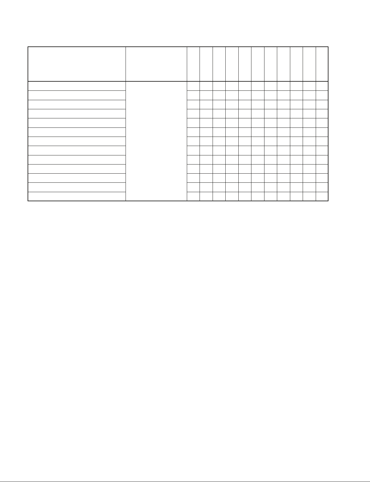
7X.20 : STATUS DATA
This return command is returned in response to the “60.20 : STATUS SENSE” command from
the DEVICE. The DEVICE returns the following data in accordance with the request.
STATUS DATA
DATA No. BIT7 BIT6 BIT5 BIT 4 BIT3 BIT2 BIT1 BIT0
0
STANDBY TENSION STOP EJECT REW F.FWD REC PLAY
1
ON RELEASE
SERVO TSO SHUTTLE JOG VAR REV/FWD STILL CUE UP
2
LOCK MODE COMPLETE
AUTO AUDIO OUT AUDIO IN OUT IN
3
MODE
SELECT EE FULL EE EDIT REVIEW AUTO EDIT PREVIEW PREROLL
4
ON ON OR CUE UP
5
6
VARIABLE VAR MEMORY AUDIO IN/OUT
7
MEMORY ACTIVE SPLIT STATUS
8
FUNCTION
9
ABORT
A
INSERT ASSEMBLE VIDEO TIME AUDIO AUDIO
LOST LOCK END OF REC
CASSETTE REF VD HARD LOCAL
OUT MISSING ERROR
CODE CH-2 CH-1
TAPE INHIBIT
Δ t REC/PLAY Δ t READY VAR
EXECUTE REC/PLAY
B
C
D
E
F
DATA No.0
DATA No.0/BIT-5 : CASSETTE OUT
BIT-5 will be set to “1” when there is no cassette threading on the DEVICE.
DATA No.0/BIT-4 : REFERENCE VIDEO MISSING
BIT-4 will be set to “1” when the REFERENCE VIDEO is not detected on the REF VIDEO
IN connector panel.
DATA No.0/BIT-2 : HARD ERROR
BIT-2 will be set to “1” when the following troubles (the tape is sticking to the drum, the tape
is slackening and so on).
DSR Series
For details, refer to the maintenance manual ERROR MESSAGE (SELF DIAGNOSTICS).
DA4 DA3 DA2 DA1
39
Page 44

DATA No.0/BIT-0 : LOCAL
BIT-0 will be set to “1” when the REMOTE/LOCAL switch on the front panel is set to
“LOCAL”.
DATA No.1
DATA No.1/BIT-7 : STANDBY
BIT-7 will be set to “1” when the DEVICE is the STANDBY ON mode.
DATA No.1/BIT-6 : TENSION RELEASE
BIT-6 will be set to “1” when the DEVICE is the TENSION RELEASE mode.
DATA No.1/BIT-5 : STOP
BIT-5 will be set to “1” when the DEVICE receives the “20.00 : STOP” command and goes
into the STOP mode.
DATA No.1/BIT-4 : EJECT
BIT-4 will be set to “1” when the DEVICE receives the “20.0F : EJECT” command and goes
into the EJECT mode.
DATA No.1/BIT-3 : REW
BIT-3 will be set to “1” when the DEVICE receives the “20.20 : REWIND” command and
goes into the REWIND mode.
DATA No.1/BIT-2 : F.FWD
BIT-2 will be set to “1” when the DEVICE receives the “20.10 : FAST FWD” command and
goes into the FAST FORWARD mode.
DATA No.1/BIT-1 : REC
BIT-1 will be set to “1” when the DEVICE receives the “20.02 : REC” command and goes
into the REC mode.
BIT-1 will be also set to “1” when “DATA No.4/BIT-4 EDIT” is set to “1”.
DATA No.1/BIT-0 : PLAY
BIT-0 will be set to “1” when the DEVICE receives the “20.01 : PLAY”, “20.02 : REC” or
“20.65 : EDIT ON” command and goes into the PLAY, REC or EDIT mode.
DATA No.2
DATA No.2/BIT-7 : SERVO LOCK
BIT-7 will be set to “1” when the DEVICE is in the condition that the drum and the capstan
servos are locked in the PLAY mode.
DATA No.2/BIT-6 : TSO MODE
BIT-6 will be set to “1” when the DEVICE is in the CAPSTAN OVERRIDE mode.
DATA No.2/BIT-5 : SHUTTLE
BIT-5 will be set to “1” when the DEVICE receives the “2X.13 : SHUTTLE FWD” or
“2X.23 : SHUTTLE REV”, and goes into the SHUTTLE mode.
40
DSR Series
Page 45

DATA No.2/BIT-4 : JOG
BIT-4 will be set to “1” when the DEVICE receives the “2X.11 : JOG FWD” or “2X.21 :
JOG REV”, command and goes into the JOG mode.
DATA No.2/BIT-3 : VAR
BIT-3 will be set to “1” when the DEVICE is receives “2X.12 : VAR FWD” or “2X.22 :
VAR REV”, command and goes into the VAR mode.
DATA No.2/BIT-2 : TAPE DIRECTION
BIT-2 shows the tape direction defined in the DEVICE.
0 = FWD
1 = REV
DATA No.2/BIT-1 : STILL
BIT-1 will be set to “1” when the DEVICE is STOP mode or STILL mode of SHUTTLE/
JOG/VAR.
DATA No.2/BIT-0 : CUE UP COMPLETE
BIT-0 will be set to “1” when the DEVICE receives “20.30 : PREROLL” and “24.31 : CUE
UP WITH DATA” commands and then cue-up operation is completed successfully.
DATA No.3
DATA No.3/BIT-7 : AUTO MODE
BIT-7 will be set to “1” when the DEVICE receives the “40.41 : AUTO MODE ON” command.
DATA No.3/BIT-3 : AUDIO OUT
DATA No.3/BIT-2 : AUDIO IN
DATA No.3/BIT-1 : OUT
DATA No.3/BIT-0 : IN
When the DEVICE receives ENTRY, PRESET and RECALL commands of each editing point
(IN, OUT, AUDIO IN or AUDIO OUT), the corresponded bit will be set to “1”, and TIMER-1
or TIME CODE data is memorized.
DATA No.4
DATA No.4/BIT-7 : SELECT EE ON
BIT-7 will be set to “1” when the DEVICE receives the “4X.30 : EDIT PRESET” command,
and furthermore, receives the “20.63” : SELECT EE ON” command.
DATA No.4/BIT-6 : FULL EE ON
BIT-6 will be set to “1” when the DEVICE receives the “20.61 : FULL EE ON” command.
DATA No.4/BIT-4 : EDIT
BIT-4 will be set to “1” when the DEVICE is in the EDIT mode, and at the same time, the
“DATA No.1/BIT-1 : REC” is also set to “1”.
DSR Series
41
Page 46

DATA No.4/BIT-3 : REVIEW
BIT-3 will be set to “1” when the DEVICE is in the REVIEW mode.
DATA No.4/BIT-2 : AUTO EDIT
BIT-2 will be set to “1” when the DEVICE is in the AUTO EDIT mode.
DATA No.4/BIT-1 : PREVIEW
BIT-1 will be set to “1” when the DEVICE is in the PREVIEW mode.
DATA No.4/BIT-0 : PREROLL OR CUE UP
BIT-0 will be set to “1” when the DEVICE receives the “20.30 : PREROLL” and “24.31 :
CUE UP WITH DATA” commands, and goes into the PREROLL and CUE-UP mode, and
BIT-0 will be also set to “1” when the PREROLL is performed in the AUTO EDIT or PREVIEW mode.
DATA No.5
DATA No.5/BIT-6 : INSERT
DATA No.5/BIT-5 : ASSEMBLE
DATA No.5/BIT-4 : VIDEO
DATA No.5/BIT-2 : TIME CODE (LTC)
DATA No.5/BIT-1 : A2 (AUDIO CH-2)
DATA No.5/BIT-0 : A1 (AUDIO CH-1)
When the DEVICE receives the “4X.30 : EDIT PRESET” commands, the corresponding bit
of DATA No.5 will be set to “1” according to the state of the DATA-1 of the EDIT PRESET
command.
Refer to “4X.30 : EDIT PRESET”.
DATA No.7
DATA No.7/BIT-7 : VAR MEMORY MODE
BIT-7 will be set to “1” when the DEVICE receives the “40.47: VAR MEN ON” command,
and goes into the VARIABLE MEMORY mode.
DATA No.7/BIT-6 : VAR MEMORY ACTIVE
BIT-6 will be set to “1” when the DEVICE goes into the VARIABLE MEMORY mode by the
“40.47: VAR MEN ON” command and the information is stored in the VAR MEMORY.
DATA No.7/BIT-5 : AUDIO SPLIT
BIT-5 will be set to “1” when the DEVICE receives the “40.45 : AUDIO SPLIT ON” command, and goes into the AUDIO SPLIT mode.
DATA No.7/BIT-0 : IN-OUT STATUS
BIT-0 will be set to “1” when the DEVICE is in the PREVIEW or AUTO EDIT mode and the
tape is running between the IN point and OUT point.
42
DSR Series
Page 47

DATA No.8
DATA No.8/BIT-6 : LOST LOCK
BIT-6 will be set to “1” when the capstan or drum servo is locked over 10 second, and then the
servo is unlocked in the PLAY, REC or EDIT mode.
When the DEVICE receives the “40.2D : LOST LOCK RESET” command, BIT-6 will be
reset.
DATA No.8/BIT-4 : END OF TAPE
BIT-4 will be set to “1” when the DEVICE detects BEGIN or END of the cassette tape.
DATA No.8/BIT-0 : REC INHIBIT
BIT-0 will be set to “1” when the REC INHIBIT plug on the cassette is set.
For DSR-60/60P, this bit will always be set to “1”.
DATA No.9
DATA No.9/BIT-7 : FUNCTION ABORT
BIT-7 will be set to “1” when the event which is defined by the “4X.C4 : DEFINE EVENT”
command, is not executed normally.
DATA No.10
DATA No.10/BIT-5 : Δ t REC/PLAY EXECUTE
BIT-5 will be set to “1” when the device goes into the Δ t REC/PLAY mode.
DATA No.10/BIT-3 : Δ t READY
BIT-3 will be set to “1” when the device is in the Δ t REC/PLAY PRESET mode and ready to
go into the Δ t REC/PLAY mode.
DATA No.10/BIT-2 : VARIABLE REC/PLAY
This bit is set to “1” when the DEVICE receives the “43.3F : Δ t REC/PLAY PRESET”
command and goes into the Δ t REC/PLAY PRESET mode.
DATA No.12
DATA No.12/BIT-3 : DA4
DATA No.12/BIT-2 : DA3
DATA No.12/BIT-1 : DA2
DATA No.12/BIT-0 : DA1
The respective bits will be set to “1” in accordance with the contents of the data which has
been added to the command, when the DEVICE receives the “4X.30 : EDIT PRESET”
command.
Refer to “4X.30 : EDIT PRESET”.
DSR Series
43
Page 48

60.2E : COMMAND SPEED SENSE
This command is used to request the TAPE SPEED command in which the DEVICE is operating. When the DEVICE receives this command, it returns the “71.2E : COMMAND SPEED
DATA” command.
71.2E : COMMAND SPEED DATA
This return command is returned in response to the “60.2E : CMD SPEED SENSE” command
from the CONTROLLER. The DEVICE returns its own tape speed data in accordance with the
request.
For the data format, refer to “2X.11 : JOG FWD”.
60.2F : VARIABLE MEMORY SPEED SENSE
This command is used to request the INITIAL SPEED DATA that is stored in the VARIABLE
MEMORY mode of the DEVICE.
When the DEVICE receives this command, it returns the “71.2F: VARIABLE MEMORY
SPEED DATA” command.
71.2F : VARIABLE MEMORY SPEED DATA
This return command is returned in response to the “60.2F: VARIABLE MEMORY SPEED
SENSE” command from the CONTROLLER. The DEVICE returns the command added to the
INITIAL SPEED DATA in accordance with the request.
For the data format, refer to “2X.11, 2X.12, 2X.13: JOG, VAR, SHUTTLE FWD” command.
6X.30 : EDIT PRESET SENSE
This command is used to request the EDIT PRESET status of the DEVICE, and the contents of
the “7X.30 : EDIT PRESET DATA” command to be sent back are assigned by DATA-1 added
to the command.
[DATA-1]
BIT-7 BIT-6 BIT-5 BIT-4 BIT-3 BIT-2 BIT-1 BIT-0
MSD (BIT 7~4) : These indicate the initial data No. of the “7X.30 : EDIT PRESET DATA”
command to be sent back.
LSD (BIT 3~0) : These indicate the number of bytes in the data to be sent back from the data in
the “7X.30 : EDIT PRESET DATA” command to be sent back.
When the “60.30” is received ; The DEVICE works same as “61.30.01” command.
MSD LSD
44
DSR Series
Page 49

7X.30 : EDIT PRESET DATA
This return command is returned in response to the “6X.30 : EDIT PRESET SENSE” command
from the CONTROLLER. The DEVICE returns the data in accordance with the request.
For the data format, refer to “4X.30 : EDIT PRESET”.
EDIT PRESET STATUS
DATA No. BIT7 BIT6 BIT5 BIT4 BIT3 BIT2 BIT1 BIT0
0 INSERT ASSEMBLE VIDEO A3 (TC) A2 (CUE) A1 (CUE)
1 DA4 DA3 DA2 DA1
2
3
4
5
6
7
8
9
A
B
C
D
E
F
60.31 : PREROLL TIME SENSE
This command is used to request the PREROLL TIME setting status of the DEVICE.
When the DEVICE receives this command, it is sent back the “74.31 : PREROLL TIME
DATA” with DATA1 to DATA4 that shows the PREROLL TIME setting status.
74.31 : PREROLL TIME DATA
This return command is returned in response to the “60.31 : PREROLL TIME SENSE” command, from the CONTROLLER. The DEVICE returns the PREROLL TIME DATA in accordance with the request.
For the data format, refer to “24.31 : CUE UP WITH DATA”.
60.32 : TAPE/AUTO SENSE
This command is used to request the TAPE/AUTO status of the DEVICE. When the DEVICE
receives this command, it returns the “71.32 : TAPE/AUTO STATUS DATA” command. The
TAPE/AUTO STATUS with DATA-1 that shows the setting will be sent back.
71.32 : TAPE/AUTO STATUS DATA
This return command is returned in response to the “60.32 : TAPE/AUTO SENSE” command from
the CONTROLLER. The DEVICE returns the value of setting in accordance with the request.
For the data format, refer to “41.32 : TAPE/AUTO SELECT”.
60.36 : TIMER MODE SENSE
This command is used to request the TIMER MODE or TIMER 1 or TIME CODE of the DEVICE.
When the DEVICE receives this command, it returns the “71.36 : TIMER MODE DATA” com-
DSR Series
mand. The TIMER MODE DATA with DATA-1 that shows the setting will be sent back.
45
Page 50

71.36 : TIMER MODE DATA
This return command is returned in response to the “60.36 : TIMER MODE SENSE” command
from the CONTROLLER. The DEVICE returns the value of setting in accordance with the
request.
[DATA-1]
00 : TIME CODE
01 : TIMER-1
02 : TIMER-2
60.3F : Δ t REC/PLAY PRESET SENSE
This command is used to request the Δ t REC/PLAY PRESET status of the DEVICE. When the
DEVICE receives this command, it returns the “73.3F : Δ t REC/PLAY PRESET DATA”
command.
73.3F : Δ t REC/PLAY PRESET DATA
This return command is returned in response to the “60.3F : Δ t REC/PLAY PRESET SENSE”
command. The DEVICE returns its own Δ t REC/PLAY PRESET status in accordance with the
request. For the data format, refer to “43.3F : Δ t REC/PLAY PRESET”.
Example) When DSR-85/85P is in the X4 mode :
73 3F 04 53 44 4D
CMD VAR REC/PLAY x4.00 Checksum
In the case of DSR-80/80P/60/60P :
72 3F 00 40 F1
CMD Normal mode x1.00 Checksum
60.50 : DA INPUT SENSE
This command is used to request the audio input signal selection status of the DEVICE. When
the DEVICE receives this command, it returns the “71.50 : DA INPUT STATUS” command.
The DA INPUT STATUS with DATA-1 that shows the setting will be sent back.
71.50 : DA INPUT STATUS
This return command is returned in response to the “60.50 : DA INPUT SENSE” command
from the DEVICE. The DEVICE returns the data that the command is added to the audio input
status.
[DATA-1]
BIT-7 BIT-6 BIT-5 BIT-4 BIT-3 BIT-2 BIT-1 BIT-0
DA3 DA2 DA1DA4
46
1 : ANALOG AUDIO INPUT
0 : DIGITAL AUDIO INPUT
DSR Series
Page 51

6X.54 : EXTENDED DA INPUT SENSE
This command is used to request the digital audio input status.
When the “60.54” is specified, this command requests the input selection status of all digital
audio input channels that the machine is equipped with.
For the return data, refer to “7X.54 : EXTENDED DA INPUT STATUS”.
When the “61.54” is specified, this command specifies the groups for every two channels by the
BIT-7 to BIT-0 of the DATA-1 as follows.
For the return data, refer to “7X.54 : EXTENDED DA INPUT STATUS”.
[DATA-1]
BIT-7 BIT-6 BIT-5 BIT-4 BIT-3 BIT-2 BIT-1 BIT-0
7X.54 : EXTENDED DA INPUT STATUS
This return command is returned in response to the “6X.54 : EXTENDED DA INPUT SENSE”
command from the CONTROLLER. The DEVICE returns the digital audio input status in
accordance with the request.
When the “60.54” is received, the status data of all channels (channel 1 through N) will be sent
back. Each channel status is composed of 4 bits data as follows.
CH-3, CH-4 CH-1, CH-2
DATA-1
CH-2 CH-1 CH-4 CH-3
MSD LSD MSD LSD
4BIT DATA 0 : ANALOG
1 : AES/EBU
2 : SDI
4 : SDTI
5 : i.LINK
E : INTERNAL SG
F : INVALID
When the “61.54” is received, the specified status data corresponding to the bitmap will be sent
back from the lower channel number. The data format is same as the return status for “60.54”.
60.58 : DA SAMPLING FREQ SENSE
This command is used to request the sampling frequency of the DEVICE’s digital audio channels. When the DEVICE receives this command, it returns the “71.58 : DA SAMPLING FREQ
STAUS” command. The DA SAMPLING FREQ STATUS with DATA-1 that shows the
sampling frequency will be sent back.
DATA-2
. . .
DSR Series
47
Page 52

71.58 : DA SAMPLING FREQ STATUS
This return command is returned in response to the “60.58 : DA SAMPLING FREQ SENSE”
command from the CONTROLLER. The DEVICE returns the data that adds the digital audio
sampling frequency data.
[RETURN DATA-1]
01 : 48.0 kHz
03 : 32.0 kHz
60.60 : VITC BYPASS SENSE
This command is used to request the VITC to be recorded. When the DEVICE receives this
command, it returns the “71.60 : VITC BYPASS STATUS” command. The VITC BYPASS
STATUS with DATA-1 that shows the setting will be sent back.
71.60 : VITC BYPASS STATUS
This return command is returned in response to the “60.60 : VITC BYPASS SENSE” command
from the CONTROLLER, it returns the VITC information to be recorded with DATA-1.
For the data format, refer to “41.60 : VITC BYPASS” command.
60.61 : TCG MODE SENSE
This command is used to request the TC GENERATOR MODE status of the DEVICE. When the
DEVICE receives this command, it returns the “72.61 : TCG MODE” command. The TC GENERATOR MODE STATUS with DATA-1 and DATA-2 that shows the setting will be sent back.
72.61 : TCG MODE
This return command is returned in response to the “ 60.61 : TCG MODE SENSE” command
from the CONTROLLER. The DEVICE returns the data that adds the TC GENERATOR
MODE data.
For the data format, refer to “42.61 : TCG MODE SELECT”.
60.70 : VIDEO INPUT SENSE
This command is used to request the video input source.
When the DEVICE receives this command, it returns the “72.70 : VICEO INPUT STATUS”
command. The VIDEO INPUT STATUS with DATA-1 and DATA-2 that shows the setting
will be sent back.
72.70 : VIDEO INPUT STATUS
This return command is returned in response to the “60.70 : VIDEO INPUT SENSE” command
from the CONTROLLER. The DEVICE returns the video input source.
The connector status is stored in the DATA-1 and the signal status is stored in DATA-2.
[DATA-1]
BIT-7 BIT-6 BIT-5 BIT-4 BIT-3 BIT-2 BIT-1 BIT-0
INTERNAL
SG
SDI
ANALOGSDTIi.LINK
48
[DATA-2]
BIT-7 BIT-6 BIT-5 BIT-4 BIT-3 BIT-2 BIT-1 BIT-0
S (Y/C) G/B/R Y/PB/PR COMPOSITE
DSR Series
Page 53

60.9E : SUPERIMPOSE SENSE
This command is used to request SUPERIMPOSE STATUS of the DEVICE. When the DEVICE receives this command, it returns the “71.9E : SUPERIMPOSE STATUS” command.
The SUPERIMPOSE STATUS with DATA-1 that shows the setting will be sent back.
71.9E : SUPERIMPOSE STATUS
This return command is returned in response to the “60.9E : SUPERIMPOSE SENSE” command from the CONTROLLER. The DEVICE returns the data that the command is added to
the SUPERIMPOSE ON/OFF data.
For the data format, refer to “41.9E : SUPERIMPOSE”.
60.AE : AUDIO MONITOR CHANNEL SENSE
This command is used to request the selection channel of the audio monitor. When the DEVICE
receives this command, it returns the “74.AE : AUDIO MONITOR CHANNEL STATUS”
command. The AUDIO MONITOR CHANNEL STATUS with DATA-1 through DATA-4 that
shows the setting will be sent back.
74.AE : AUDIO MONITOR CHANNEL STATUS
The return command is returned in response to the “60.AE : AUDIO MONITOR CHANNEL
SENSE” command. The DEVICE returns the current selection.
For the data format, refer to the “44.AE : AUDIO MONITOR CHANNEL SELECT” command.
60.C2 : TIMELINE SOURCE SENSE
This command is used to inquire which source is selected as the source of timeline.
71.C2 : TIMELINE SOURCE
This return command is returned in response to the “60.C2 : TIMELINE SOURCE SENSE”
command.
[DATA-1]
00 : Internal Clock (Built-in clock which is synchronized with the reference video signal)
60.C3 : TIMELINE TIME SENSE
This command is used to request the present time value of the TIMELINE.
When the exact time value is required, the TIMELINE TIME SENSE and the RETURN must be
completed within the second field while it is synchronized with the reference video signal of the
device.
75.C3 : TIMELINE TIME
This return command is returned in response to the “60.C3 : TIMELINE TIME SENSE”
command, and returns the following data.
[DATA-1]
This indicates the source of TIMELINE which is selected at present.
00 : Internal Clock (Built-in clock which is synchronized with the reference video signal)
DSR Series
[DATA-2 to DATA-5]
This indicates the present time value of the TIMELINE.
For the data format, refer to “24.31 : CUE UP WITH DATA”.
49
Page 54

62.C4 : EVENT DATA SENSE
This command is used to request the contents of the event which is defined by the “4X.C4 :
DEFINE EVENT” command.
[DATA-1, DATA-2]
DATA-1
Event No.
(Lower byte)
DATA-2
Event No.
(Upper byte)
This specifies the event number which is requested by DATA-1 and DATA-2. The event
number is a 16-bit data from 0001h to FFFFh, in which 0000h cannot be specified.
7X.C4 : EVENT DATA
This return command is returned in response to the “62.C4 : EVENT DATA SENSE” command
from the CONTROLLER. The contents of definition of event are returned. If the specified
event has not been defined yet, “70.C4” is returned.
For the data format, refer to “4X.C4 : DEFINE EVENT”.
60.C6 : TIMELINE STATUS SENSE
This command is used to request the various statuses such as the status of the buffer for event
definition, execution status of event, etc.
50
DSR Series
Page 55

75.C6 : TIMELINE STATUS
This return command is returned in response to the “60.C6 : TIMELINE STATUS SENSE”
command.
[DATA-1]
This indicates the execution status of the defined event.
bit-4
0 : No errors are detected during execution of events.
1 : An error occurred in the event which is being executed.
The event in which the error occurred can be determined by the “61.C8 : UNSUCCESSFUL EVENT SENSE” command.
bit-3
0 : Preparation to run the timeline is ready.
1 : Preparation to run the timeline is not ready yet.
bit-1, bit-0
0 0 : Event is not defined yet.
0 1 : Among the already defined events, some events have not been executed yet.
Un-executed events can be determined by the “61.C7 : EVENT QUEUE
SENSE” command.
1 0 : All of the defined events are executed.
[DATA-2, DATA-3]
The remaining capacity of the event buffer is indicated by the numbers of events. This data
consists of a lower byte in which DATA-2 is stored, and an upper byte in which DATA-3 is
stored. It indicates the remaining capacity up to the maximum 65535 equivalent events with
FFFFh.
[DATA-4, DATA-5]
The event number which will be assigned during next execution of the “4X.C4 : DEFINE
EVENT” command is indicated by 16-bit data. The lower byte is assigned to DATA-4 and the
upper byte is assigned to DATA-5.
61.C7 : EVENT QUEUE SENSE
This command is used to request which event is waiting for execution among the events that are
defined by the “4X.C4 : DEFINE EVENT” command.
[DATA-1]
This specifies which of the events waiting for execution is to be returned.
bit-4
0 : This specifies to start returning from the top of the event buffer.
1 : The next data after the event that is returned in the previous time among the events
waiting for execution, is started to be returned.
DSR Series
bit-2 ~ bit-0
This specifies how many events’ worth of data are to be returned. A maximum of 7 can
be specified.
51
Page 56

7X.C7 : EVENT QUEUE
This return command is returned in response to the “61.C7 : EVENT QUEUE SENSE” command.
The events which are waiting for execution are returned in the order of event number.
The maximum number of events which can be returned at once is 7 events. When the specified
number of data is less than 1 or when “70.C7” is returned, it indicates that there is no remaining
data.
[DATA-1, DATA-2]
This indicates an event number (0001h to FFFFh) which has not been executed yet.
The lower byte is assigned to DATA-1 and the upper byte is assigned to DATA-2.
[DATA-3, DATA-4]
This indicates an event number (0001h to FFFFh) which has not been executed yet. The lower
byte is assigned to DATA-3 and the upper byte is assigned to DATA-4.
.
.
.
.
61.C8 : UNSUCCESSFUL EVENT SENSE
This command is used to request information about the event in which an error is detected. The
event in which an error is detected is stored in the unsuccessful EVENT buffer as an unsuccessful EVENT. They are stored in the order of error detection.
DSR series VTR has the capacity of 5 events as the unsuccessful EVENT buffer.
[DATA-1]
This specifies which unsuccessful EVENT is to be returned.
bit-4
0 : Return is started from the top of the unsuccessful EVENT buffer.
1 : Return is started from the next data after the unsuccessful EVENT that was returned
previously.
bit-2 ~ bit-0
This specifies how many events’ worth of data are to be returned. A maximum of 5 can
be specified.
52
DSR Series
Page 57

7X.C8 : UNSUCCESSFUL EVENT
This return command is returned in response to the “61.C8 : UNSUCCESSFUL EVENT
SENSE” command. Data equivalent to one event consists of 3 bytes as described below, and is
returned.
The maximum number of events which can be returned at once is 5 events. When the specified
number of data is less than 1 or when “70.C8” is returned, it indicates that there is no remaining
data. When the data exceeds the capacity of the unsuccessful EVENT buffer, subsequent data
will not be stored. The unsuccessful EVENTs are deleted from the buffer using the “42.C5 :
CLEAR EVENT” command.
[DATA-1, DATA-2]
This indicates the event number (0001h to FFFFh) of the unsuccessful EVENTs. The lower byte
is assigned to DATA-1 and the upper byte is assigned to DATA-2.
[DATA-3]
This indicates the contents of the detected error.
bit-2 bit-1 bit-0
0 0 1 : The event was executed, but an error is detected.
0 1 0 : The event could not be executed as it has an error.
1 0 0 : The event has not been executed even though the trigger time has
.
.
.
.
elapsed.
DSR Series
53
Page 58

7-2. DSR-DR1000/A Disk Command (Ver 1.10 or later)
1. OPEN PLAY & CLOSE
(1) OPEN PLAY
The OPEN PLAY command is used in the DSR-DR1000 to cue up to the specified clip, and to play back
the Playlist that is created by the VFL Download or saved by the Clip menu.
The DSR-DR1000 identifies Playlist from Clip by the extension “.dlt” whether the extension “.dlt” is
added or not to the end of a filename. If the extension “.dlt” is added, the DSR-DR1000 identifies the file
as a Playlist. If it is not added, the DSR-DR1000 identifies that a Clip is specified.
Note that the OPEN PLAY command is invalid in the following cases due to the DSR-DR1000 system
configuration.
. When the Disk menu is being opened.
. When the Network menu is being opened.
. When the Clip menu is being opened.
. When the Clip Play is in progress.
. When the Repeat mode is ON.
Command format
Item Size Value Description
DC 1 0xXX Data Count
CMD1 1 0x16 Command1
CMD2 1 0x00 Command2
DATA1 1 0xXX PORT ID
DATA2 1 0xXX OPTION
DATA3 1 0xXX DRIVE ID
DATA4 n 0xXX.. FILE NAME
DATA5 3 0xXX CHANNEL BITMAP 1
0xXX CHANNEL BITMAP 2
0xXX CHANNEL BITMAP 3
DATA6 4 0xXX START TIME CODE (Frames)
0xXX START TIME CODE (Seconds)
0xXX START TIME CODE (Minutes)
0xXX START TIME CODE (Hours)
DATA7 4 0xXX DURATION (Frames)
0xXX DURATION (Seconds)
0xXX DURATION (Minutes)
0xXX DURATION (Hours)
PORT ID : It is ignored in the DSR-DR1000.
OPTION : An option is specified by bit.
DRIVE ID : XIt is fixed to 0x00.
FILE NAME : It specifies a Playlist to be opened or a Clip to be cued up.
CHANNEL BITMAP : It is ignored in the DSR-DR1000.
START TIME CODE : The 4-byte timecode data in BCD format.
DURATION : It is ignored in the DSR-DR1000.
The option that can be specified with the DSR-DR1000 is the START TIME CODE only. Other options
are ignored even if they are set. The START TIME CODE can be specified with the FTC only and the
FTC indicates the specified Playlist or the position from the top of the Clip.
54
DSR Series
Page 59

The statuses at OPEN PLAY in the DSR-DR1000 are shown below.
FILE OPEN STATUS Value Description
FILE OPEN MODE 0x00 OPEN PLAY
FILE OPEN STATUS 0x01 NOT OPENED
0x02 IN PROGRESS
0x08 OPEN COMPLETE
0x10 FAIL, FILE NOT FOUND
0x15 FAIL, ILLEGAL VALUE
0x1A FAIL, DRIVE NOT READY
0x1F FAIL, OTHER REASONS
Status of the OPEN PLAY command of the DSR-DR1000 is indicated by the EJECT bit (bit-4) of the
status data of the VTR command. When the EJECT bit is changed from 1 to 0, it indicates that the OPEN
PLAY operation is completed.
DATA No. BIT7 BIT6 BIT5 BIT4 BIT3 BIT2 BIT1 BIT0
1 STANDBY TENSION STOP 0 REW F.FWD REC PLAY
ON RELEASE (EJECT)
m
. If the Stop button on the front panel is pressed, or the DSR-DR1000 has entered either the Disk menu
or Network menu or Repeat Function while the Playlist is being opened, the DSR-DR1000 returns to
the state that it plays back the default.dlt. (The screen returns to the previous screen before OPEN.)
. The OPEN PLAY command can be used also when it is not in the CLOSE state (i.e., when the EJECT
bit is ON). However, you cannot confirm if the OPEN PLAY has terminated or not from the EJECT bit
information. (The EJECT bit does not change.)
(2) CLOSE
In the DSR-DR1000, the CLOSE command is used to set the EJECT bit of the Status data of the VTR
command, and to move the mode to the Stop mode if the DSR-DR1000 is not in the stop mode before it
receives the CLOSE command.
Command format
Item Size Value Description
DC 1 0x01 Data Count
CMD1 1 0x19 Command1
CMD2 1 0x01 Command2
DATA1 1 0x00 FILE HANDLE
Conditions of operation
FILE HANDLE 0x00 only
Status of the CLOSE command of the DSR-DR1000 is indicated by the EJECT bit (bit-4) of the status
data of the VTR command. When the EJECT bit is 1, it indicates that the CLOSE operation is completed.
DATA No. BIT7 BIT6 BIT5 BIT4 BIT3 BIT2 BIT1 BIT0
1 STANDBY TENSION STOP 1 REW F.FWD REC PLAY
ON RELEASE (EJECT)
DSR Series
55
Page 60

(3) Sequence of OPEN PLAY and CLOSE
In the DSR-DR1000, since the OPEN PLAY command the CLOSE command are required as a pair, they
are described at the same time as follows.
Completion of the OPEN PLAY command the CLOSE command can be checked in the DSR-DR1000,
by the EJECT bit (bit-4) of the status data of the VTR command.
Editor DSR-DR1000
1 Disk : Close
2 VTR : Ack
3 VTR : Status Sense
4 VTR : Status Data
5 Disk : Open Play
6 VTR : Ack
7 VTR : Status Sense
8 VTR : Status Data
In the DSR-DR1000, a series of the OPEN PLAY command the CLOSE command are expected to be
issued and executed as described above as the correct sequence of operation.
At the timing 1, the DSR-DR1000 receives the CLOSE command and performs the CLOSE processing.
In order to check that the CLOSE processing is completed, the Status Sense is issued to the DSR-DR1000
at the timing 3 and the status data is returned at the timing 4. If the EJECT bit (bit-4) of the status data
is 1, completion of the CLOSE command is confirmed.
DSR-DR1000 receives the OPEN PLAY command at the timing 5, and performs the OPEN PLAY
processing. In order to check that the OPEN PLAY processing is completed, the Status Sense is issued to
the DSR-DR1000 at the timing 7 and the status data is returned at the timing 8. If the EJECT bit (bit-
4) of the status data is 0, completion of the OPEN PLAY command is confirmed.
56
DSR Series
Page 61

2. VFL DOWNLOAD DATA
In the DSR-DR1000, all of the VFL DOWNLOAD DATA commands including VFL DOWNLOAD
DATA CLEAR command, the VFL DOWNLOAD DATA SET command and the VFL DOWNLOAD
WRITE command result in an error when the DSR-DR1000 is in any of the following states due to the
DSR-DR1000 system configuration.
. When the Disk menu is being opened.
. When the Network menu is being opened.
. When the Clip menu is being opened.
. When the Repeat mode is ON.
(1) VFL DOWNLOAD CLEAR
In order to perform the VFL DOWNLOAD processing in the DSR-DR1000, the VFL DOWNLOAD
DATA CLEAR command, the VFL DOWNLOAD DATA SET command and the VFL DOWNLOAD
DATA WRITE command must be issued in the above-described order unless each of these commands
does not issue an error. When the DSR-DR1000 receives the VFL DOWNLOAD DATA CLEAR
command, it checks inside the DSR-DR1000, that sequence of the VFL DOWNLOAD commands is
correct without an error.
Command format
Item Size Value Description
DC 1 0x01 Data Count
CMD1 1 0x10 Command1
CMD2 1 0x43 Command2
Statuses of the VFL DOWNLOAD DATA CLEAR command in the DSR-DR1000 are shown below.
SYSTEM STATUS Value Description
Command Status 0x43 VFL DOWNLOAD DATA CLEAR
Execution Status 0x00 COMPLETE
0x01 IN PROGRESS
0x02 FAIL
(2) VFL DOWNLOAD DATA SET
In the DSR-DR1000, the VFL DOWNLOAD DATA SET command is used to create the Playlist by
specifying the name of the Clip that is stored in the DSR-DR1000.
Command format
Item Size Value Description
DC 1 0xXX Data Count
CMD1 1 0x10 Command1
CMD2 1 0x41 Command2
DATA1 1 0x0X OPTION
DATA2 n 0xXX.. VFL NAME
DATA3 n 0xXX.. VFL DATA
OPTION Used to specify TIME CODE only. (FTC and LTC can be set.)
VFL NAME The VFL filename should be either [*.dlt] or [*]. Length of a filename is limited up to 20
characters for [*.dlt] including [.dlt]. However, there are limitations when using the file as
shown below. Refer to the page after next “Limitations of VFL NAME”.
VFL DATA The maximum number of events that can be handled are 200. Refer to the next page and
onwards regarding the restrictions on VFL TEXT and the VFL Format.
DSR Series
57
Page 62

VFL Format
[title_field] [CRLF]
[out_ch] [CRLF]
[in_point] [SP] [out_point] [SP] [drive_id] [SP] [filename] [SP] [av_select] ( [SP] [OPTION] [SP] [OPTION] ...[OPTION] )[CRLF]
[in_point] [SP] [out_point] [SP] [drive_id] [SP] [filename] [SP] [av_select] ( [SP] [OPTION] [SP] [OPTION] ...[OPTION] )[CRLF]
.
.
.
[in_point] [SP] [out_point] [SP] [drive_id] [SP] [filename] [SP] [av_select] ( [SP] [OPTION] [SP] [OPTION] ...[OPTION] )[CRLF]
.
.
.
[EOF]
OPTION may be omitted → Downward compatibility with the current format is maintained.
Contents of OPTION :
–Video_**** (**** : hex number) Unity = 0x4000
–Chroma_**** (**** : hex number) Unity = 0x4000
–Hue_**** (**** : hex number) Unity = 0x0000 (2’s Compliment)
–Setup_**** (**** : hex number) Unity = 0x0000 (2’s Compliment)
–Audio_****** (**** : hex number) Unity = 0x100000
–Fade_* (* : 0 or V or X) Fade effect is applied to the end of specified area.
Limitations of VFL TEXT
Limitations of the VFL TEXT that can be used in the DSR-DR1000 are shown below.
. The supported formats of the timecode data are LTC and FTC. (Attribute.dat of each Clip is used to
identify LTC.)
. A clip cannot be created during recording (It cannot be opened).
. When out_ch is specified, only the video signal can be used. The other channels are not supported.
. MUTE and FREEZE are not supported as filename of the VFL text.
. VFL in VFL is not supported.
. Extended VFL is not supported.
. With regard to av_select, only [*] is supported.
. With regard to the Drive ID, only 0 is supported.
. Title_field is not used as Data. (Even when there is no title_field, however, the subscript CRLF is
required.)
. The minimum Duration that can be registered at 1 Event is 5 Frames.
58
DSR Series
Page 63

Limitations of VFL NAME
In the DSR-DR1000, the VFL NAME that creates problem in the system configuration cannot be used as
shown below.
. The host system that performs the VFL downloading cannot specify “default.dlt” or “cliplist0.dlt”or
“RepeatTmp.dlt” as the VFL NAME. (The filenames from which [.dlt] is deleted from the abovedescribed NAMEs cannot also be used.) At the same time, “00XXX” that is used as the name of Clip in
the DSR-DR1000 cannot also be specified.
. For the files using [*], up to 16 characters in the range of 20 to 4 can be used because [.dlt] is added
later inside the system. ([*] means wild card.) A maximum of seven VFLs can be registered. If any
VFL that uses the already registered VFL NAME, the existing VFL will be overwritten when it is
downloaded and saved.
STATUS processing
Statuses of the VFL DOWNLOAD DATA SET in the DSR-DR1000 are shown below.
SYSTEM STATUS Value Description
Command Status 0x41 VFL DOWNLOAD DATA SET
Execution Status 0x00 COMPLETE
0x01 IN PROGRESS
0x02 FAIL
0x03 FAIL, ILLEGAL DATA
0x04 FAIL, CURRENT_STATUS ERROR
0x21 FAIL, FILE IS NOT EXIST
0x26 FAIL, TIME CODE IS OUT OF RANGE OF THE FILE
0x28 FAIL, LACK OF RECORD ENTRY
(3) VFL DOWNLOAD DATA WRITE
In the DSR-DR1000, the VFL DOWNLOAD DATA WRITE command is used to register the Playlist
that is created on the basis of the VFL NAME and VFL TEXT that are specified by the VFL DOWNLOAD DATA SET command.
Command format
Item Size Value Description
DC 1 0xXX Data Count
CMD1 1 0x10 Command1
CMD2 1 0x42 Command2
DATA1 1 0xXX DRIVE ID
DATA2 n 0xXX.. VFL NAME
DRIVE ID 0x00 only
VFL NAME No processing is executed even if it is specified.
Statuses of the VFL DOWNLOAD DATA WRITE command in the DSR-DR1000 are shown below.
SYSTEM STATUS Value Description
Command Status 0x42 VFL DOWNLOAD DATA WRITE
Execution Status 0x00 COMPLETE
0x01 IN PROGRESS
0x02 FAIL
0x03 FAIL, NOT REGISTRATION
DSR Series
59
Page 64

(4) VFL DOWNLOAD Sequence
In the DSR-DR1000, a series of the commands expected to be issued and executed as described below as the correct
sequence of the VFL DOWNLOAD DATA operation.
The time interval between the command outputs must be less than two seconds.
Editor DSR-DR1000
1 Disk : VFL Download Clear
2 VTR : Ack
3 Disk : System Status Sense
4 Disk : System Status
5 Disk : VFL Download Data Set
6 VTR : Ack
7 Disk : VFL Download Data Set
8 VTR : Ack
9 Disk : System Status Sense
!/ Disk : System Status
!- Disk : VFL Download Data Write
!= VTR : Ack
![ Disk : System Status Sense
!] Disk : System Status
In the DSR-DR1000, the command that will be used to check error related to the VFL DOWNLOAD DATA command
becomes the System Status. The identification number of the command is set in the No. 544th CMD status of the System
Status Table. Result of execution is reflected on the No. 545th EXEC status of the System Status Table. (Refer to “(6)
SYSTEM STATUS” on page 63.)
In the DSR-DR1000, sequence of executing the VFL DOWNLOAD DATA command has the following limitations.
. In order to execute the VFL DOWNLOAD DATA command in the DSR-DR1000, the VFL DOWNLOAD DATA
CLEAR command, the VFL DOWNLOAD DATA SET command and the VFL DOWNLOAD DATA WRITE command must be issued in the above-described order. Any other command other than the System Status Sense should not be
inserted in between the above-described commands.
. In order to check error in the VFL DOWNLOAD command, the System Status Sense should be used.
The point that requires attention in the above-described sequence of executing the VFL DOWNLOAD DATA command is
the steps 5 and 7 where the VFL DOWNLOAD DATA SET command is repeated twice consecutively. In case if the
VFL TEXT command cannot be contained in a single command, top of the command is changed from 0x30 to 0x31 that
enables to send the VFL DOWNLOAD DATA SET command continuously. In such a case, the VFL DOWNLOAD
DATA SET command processing is completed when the last 0x30 is received and the data is registered in the memory. If
top of a command is 0x31, and if the VFL DOWNLOAD DATA SET command continues after that, the system status
becomes IN PRO unless the registered data issues and error.
60
DSR Series
Page 65

3. DELETE
(1) DELETE
In the DSR-DR1000, “DELETE” means the DELETE (CLIP/Playlist) processing performed by using the
ALL DELETE/CLIP DELETE operation commanded by Front Panel (to be abbreviated simply as FP
hereafter) and the DELETE (CLIP/Playlist) operation commanded by the Disk command supplied from
the CONTROL DEVICE. The “ALL DELETE” operation means to delete laterally all files of the CLIPrelated files and Playlist and others, to return the system to the initial status. The “CLIP DELETE” (FP/
Disk Com) operation means to remove the targeted CLIP-related files using the default.dlt and Playlist, so
that the truncation operation and other operations are executed. If the mode is playback mode, the current
position and TC are changed in the “CLIP DELETE” (FP/Disk Com) operation. The “DELETE” command of the Disk command has the two types: one is to delete the CLIP-relate files from FP in the same
way as CLIP DELETE, while the other type is to delete the Playlist-related files.
Disk Command Delete
<Operation>
. While the DISK MENU/NETWORK MENU/CLIP MENU is in progress, it performs the exclusive OR
operation.
. While CLIP playback is in progress or while REC is in progress, it performs the exclusive OR operation.
. When a Playlist is specified, the Playlist and the reference files are deleted.
. When a CLIP is specified, the CLIP-related files and -folders are deleted from the related files such as
default.dlt and are updated.
. Upon completion of deletion, the file default.dlt is set to the playback-ready state.
. Upon completion of deletion, the Exec Status of Drive Status will be updated.
. If a Clip before the Current Clip is deleted, the tape is cued up to the same position (same picture)
where the current TC is changed.
. If a Clip after the Current Clip is deleted, the tape is cued up to the same position (same picture) as the
Current Clip.
. If any Clip exists when the Current Clip is deleted, tape cues up to the IN point of the next Clip.
. Upon completion of deletion of the Current Clip that is the last Clip, the tape is cued up to the OUT
point of the previous Clip.
. If the Current Clip is deleted when any Clip does not exist, the picture becomes all black.
. When a Clip is going to be deleted, any extension (such as .dlt) should not be added to the file to be
deleted, on the command.
. When a Playlist is going to be deleted, an extension (such as .dlt) should be added to the file to be
deleted, on the command.
Command format
Item Size Value Description
DC 1 0xXX Data Count
CMD1 1 0x13 Command1
CMD2 1 0x03 Command2
DATA1 1 0x00 DRIVE ID
DATA2 n 0xXX.. FILE NAME
DRIVE ID Fixed to 0x00
FILE NAME Filename to be deleted
SYSTEM STATUS Value Description
Command Status 0x03 DELETE
Execution Status 0x00 COMPLETE
0x01 IN PROGRESS
0x02 FAIL
0x21 FAIL, SOURCE FILE IS NOT EXIST
0x23 FAIL, THE FILE IS OPEN
DSR Series
61
Page 66

(2) DELETE Sequence
In the DSR-DR1000, a series of the commands expected to be issued and executed as described below as
the correct sequence of the DELETE operation.
Editor DSR-DR1000
1 Disk : Delete
2 VTR : Ack
3 Disk : Drive Status Sense
4 Disk : Drive Status
In the DSR-DR1000, the command of the DELETE command that is used to check the error, becomes the
Drive Status. The identification number of the command is entered in the CMD STATUS that is the 0th
status of the Drive Status Table. Result of the execution is reflected on the 1st status that is the EXEC
STATUS.
(3) Example of the Cue Up Position for Your Reference
Examples of the CLIPs that are displayed on the PLAY side after receipt of the DELETE command and
upon completion of DELETE of the CLIP, are shown below your reference.
Examples numbers 1 through 7 are the examples in the status when CLIP00001/CLIP00002/CLIP00003/
CLIP00004/CLIP00005 exist.
Example number 8 is the example in the status when CLIP00001 only exists.
No. Current Clip Clip to be Deleted Cue Up Clip
1 CLIP00003 CLIP00003 CLIP00004 IN point
2 CLIP00001 CLIP00001 CLIP00002 IN point
3 CLIP00005 CLIP00005 Number of CLIP00004 OUT points
4 CLIP00003 CLIP00001 CLIP00003 TC only changes.
5 CLIP00003 CLIP00002 CLIP00003 TC only changes.
6 CLIP00003 CLIP00005 CLIP00003 does not change.
7 CLIP00003 CLIP00004 CLIP00003 does not change.
8 CLIP00001 CLIP00001 BLACK
62
DSR Series
Page 67

4. Sense Command
The Sense Request and the Sense Return of the Disk command that are supported by the DSR-DR1000
are shown below.
(1) DRIVE STATUS SENSE
In the DSR-DR1000, the DRIVE STATUS SENSE is the command that aims at inquiring the DRIVE
STATUS (aiming at confirmation of the processing status of the DELETE command, and aiming at confirmation of the remaining free capacity of the recording hard disk (to be abbreviated simply as HD hereafter)).
Command format
Item Size Value Description
DC 1 0x03 Data Count
CMD1 1 0x14 Command1
CMD2 1 0xD0 Command2
DATA1 1 0x00 DRIVE ID
DATA2 1 0xXX DRIVE STATUS TABLE No.
DATA3 1 0xXX LENGTH
Requests that cannot be accepted due to their contents
1. Requesting the Data Count using a value other than 0x03.
2. Requesting the DRIVE ID using a value other than 0x00.
3. Requesting the LENGTH using a value of 254 or more.
4. Requesting the DRIVE STATUS TABLE No. + LENGTH using a value of 257 or more.
If any request having the above-described contents is issued, the DRIVE STATUS is returned as
“DRIVE STATUS (without any additional data)”
(2) DRIVE STATUS
In the DSR-DR1000, the DRIVE STATUS is the status that aims at the replies for the inquiry of the
DELETE processing status and inquiry for the remaining capacity of HD.
Command format
Item Size Value Description
DC 1 0xXX Data Count
CMD1 1 0x15 Command1
CMD2 1 0xD0 Command2
DATA1 1 0xXX DRIVE ID
DATA2 1 0xXX DRIVE STATUS TABLE No.
DATA3 1 0xXX DRIVE STATUS VALUE
DC
Received with DRIVE STATUS SENSE. The LENGTH + 2 (DRIVE ID/
DRIVE STATUS TABLE No.)
DRIVE ID Received with DRIVE STATUS SENSE. The DRIVE ID value
DRIVE STATUS TABLE No. Received with DRIVE STATUS SENSE. The DRIVE STATUS TABLE
No. value
DRIVE STATUS VALUE
DRIVE STATUS TABLE DATA as many as the number of the LENGTHs
starting from the TABLE NUMBER specified by the DRIVE STATUS SENSE.
DSR Series
63
Page 68

Items that are set in the DSR-DR1000.
TableNo.0 : Command Status
TableNo.1 : Exec Status
TableNo.32-39 : VIDEO REMAIN SIZE (The same value as that of AUDIO)
TableNo.40-47 : AUDIO REMAIN SIZE (The same value as that of VIDEO)
DRIVE STATUS TABLE
Category Table No. Size ID = 0 ID! = 0 Item
COMMAND STATUS 000 1 OK NG CMD STATUS
001 1 OK NG EXEC STATUS
AV REMAINING SIZE 032-039 8 OK OK VIDEO REMAINING SIZE
040-047 8 OK OK AUDIO REMAINING SIZE
OK : senses valid value.
NG : senses value which is not valid.(e.g.0x00)
For all items other than what are listed above, these items are filled with 0x00 to make up the DRIVE
STATUS VALUE.
If there is any abnormality in the DRIVE STATUS SENSE request, the DRIVE STATUS VALUE will
not added by setting DC = 0x00.
(3) FILE SYSTEM DATA SENSE
In the DSR-DR1000, the FILE SYSTEM DATA SENSE is the command that aims at inquiry of the FILE
SYSTEM DATA (File Entry for DSR-DR1000).
The FILE SYSTEM DATA SENSE command is issued in order to obtain the return which is the File
Entry Data that tells the host system the Clips in the DSR-DR1000, the Playlist created by VFL and the
Playlist information that is created by the Front Panel and then saved.
The host system that wants to use this command must recognize that the maximum number of the File
Entries of the DSR-DR1000 is 507 and at the same time every single File Entry consists of 112 bytes.
Command format
Item Size Value Description
DC 1 0x0X Data Count
CMD1 1 0x14 Command1
CMD2 1 0x81 Command2
DATA1 1 0x00 DRIVE ID
DATA2 1 0xXX AREA CODE
DATA3 4 0xXXXXXXXX START ADDRESS
DATA4 1 0xXX LENGTH
Requests that cannot be accepted due to their contents
1. Any value other than 0x10 (File Entry) is used for inquiring AREA CODE
2. Any value other than 225 (2 File Entry) is used for inquiring LENGTH.
3. Any value other than 56784 (507 * 112) is used for inquiring START ADDRESS.
4. Any value other than 113 is used for inquiring LENGTH when the START ADDRESS is located at
the last position (0xDD60).
5. Any value other than 113 is used for inquiring the (START ADDRESS % 112) + LENGTH.
6. Any value other than 225 is used for inquiring LENGTH when the START ADDRESS is in multiples
of 112 (not including the last address).
If the request cannot be accepted due to their contents, only the FILE SYSTEM DATA is returned as the
reply with the “FILE SYSTEM DATA(with no additional data)”.
64
DSR Series
Page 69

(4) FILE SYSTEM DATA
In the DSR-DR1000, the FILE SYSTEM DATA is the status that aims at the reply for the DSR-DR1000
File Entry.
Command format
Item Size Value Description
DC 1 0xXX Data Count
CMD1 1 0x15 Command1
CMD2 1 0x81 Command2
DATA1 1 0x00 DRIVE ID
DATA2 1 0xXX AREA CODE
DATA3 4 0xXXXXXXXX START ADDRESS
DATA4 n 0xXX FILE SYSTEM DATA
DC Received with FILE SYSTEM DATA SENSE. The LENGTH + 6 (DRIVE ID +
AREA CODE + START ADDRESS)
DRIVE ID Received with FILE SYSTEM DATA SENSE. The DRIVE ID
AREA CODE Received with FILE SYSTEM DATA SENSE. The AREA CODE
START ADDRESS Received with FILE SYSTEM DATA SENSE. The START ADDRESS
FILE SYSTEM DATA Received with FILE SYSTEM DATA (File Entry Data for the specified Playlist)
DSR Series
65
Page 70

The items that are supported as the File Entry in the DSR-DR1000 are identified by the round marks (O)
and by the triangle marks(T) in the following table.
At the same time, the items that are shown with the crossing mark (X) are filled with 0x00 to create the
FILE SYSTEM DATA.
ITEM SIZE (Byte) VALUE INDEX GATHER
FILE_NAME 24 0-23 O
FILE_ATR 2 0x8005 24-25 T
WCF 2 26-27 X
GROUP 2 28-29 X
OWNER 2 30-31 X
RE_V 4 32-35 X
I-NODE 2 0xFFFF 36-37 T
CA_PROTECT 2 0x01FF 38-39 T
CA_ATR_AV INFO 1 40 X
A_CH 1 41 X
SECT 2 42-43 X
CA_ATR_V TYPE 1 44 X
FRM 1 45 X
SECT 2 46-47 X
CA_ATR_A1 TYPE 1 48 X
BRR 1 49 X
SECT 1 50 X
SMPL 1 51 X
CA_ATR_A2 to A8 28 52-79 X
CA_SIZE_V 8 80-87 O
CA_DATE 4 88-91 X
CA_TIME 4 92-95 X
CA_DUR 4 96-99 O
CA_STC 4 100-103 O
CA_SOM 4 104-107 O
CA_EOM 4 108-111 O
The items whose VALUEs are shown in the above table are set to the fixed values. The items of CA_STC
and the CA_SOM are set to the fixed value of 00:00:00:00. The items CA_SIZE_V and CA_EOM are set
to the values which are calculated from Duration.
66
DSR Series
Page 71

(5) SYSTEM STATUS SENSE
In the DSR-DR1000, the SYSTEM STATUS SENSE is the command that aims at inquiry of the SYSTEM STATUS (inquiring the VFL DOWNLOAD processing status check).
Command format
Item Size Value Description
DC 1 0x04 Data Count
CMD1 1 0x11 Command1
CMD2 1 0xD0 Command2
DATA1 2 0xXX TABLE NUMBER (Lower)
0xXX TABLE NUMBER (Upper)
DATA2 2 0xXX REQUEST LENGTH (Lower)
0xXX REQUEST LENGTH (Upper)
Requests that cannot be accepted due to their contents
1. Requesting the DC using a value other than 0x04.
2. Requesting the TABLE NUMBER + REQUEST LENGTH using a value of 1025 or more
3. Requesting the REQUEST LENGTH using a value of 254 or more.
If any request having the above-described contents is issued, the SYSTEM STATUS is returned as
“SYSTEM STATUS (without any additional data)”
(6) SYSTEM STATUS
In the DSR-DR1000, the SYSTEM STATUS is the status that aims to inquiring the processing status of
the VFL DOWNLOAD.
Command format
Item Size Value Description
DC 1 0xXX Data Count
CMD1 1 0x12 Command1
CMD2 1 0xD0 Command2
DATA1 2 0xXX TABLE NUMBER (Lower)
0xXX TABLE NUMBER (Upper)
DATA2 n 0xXX STATUS TABLE DATA
DC Received with SYSTEM STATUS SENSE. The REQUEST LENGTH + 2
(TABLE NUMBER)
TABLE NUMBER Received with SYSTEM STATUS SENSE. The TABLE NUMBER value
STATUS TABLE DATA The SYSTEM STATUS TABLE DATA as many as the number of RE-
QUEST LENGTHs starting from the TABLE NUMBER specified by the
SYSTEM STATUS SENSE
The items that are set in the DSR-DR1000
TableNo.544 : Command Status
TableNo.545 : Exec Status
SYSTEM STATUS TABLE
Category Size Item (MAV-555/2000) Item (MAV-1000/1200) Initial Value
COMMAND STATUS (544-549) 1 CMD STATUS 0xFF
1 EXEC STATUS 0x00
For all items other than what are listed above, these items are filled with 0x00 to make up the STATUS
TABLE DATA.
If there is any abnormality in SYSTEM STATUS SENSE request, the STATUS TABLE DATA will not
added by setting DC = 0x00.
DSR Series
67
Page 72

(7) FILE ENTRY DATA SENSE
In the DSR-DR1000, the FILE ENTRY DATA SENSE is the command that aims at inquiry of the FILE
ENTRY DATA (File Entry while recording/playback is in progress).
Command format
Item Size Value Description
DC 1 0x03 Data Count
CMD1 1 0x1A Command1
CMD2 1 0x82 Command2
DATA1 1 0xXX FILE HANDLE
DATA2 1 0xXX TABLE NUMBER
DATA3 1 0xXX REQUEST LENGTH
Requests that cannot be accepted due to their contents
1. Requesting the FILE HANDLE using a value other than 0x00.
2. Requesting the TABLE NUMBER + REQUEST LENGTH using a value more than 113.
If any request having the above-described contents is issued, the FILE ENTRY DATA is returned as
“FILE ENTRY DATA (without any additional data)”
(8) FILE ENTRY DATA
In the DSR-DR1000, the FILE ENTRY DATA is the status that aims at the reply against the inquiry for
the File Entry while recording/playback is in progress.
Command format
Item Size Value Description
DC 1 0xXX Data Count
CMD1 1 0x1B Command1
CMD2 1 0x82 Command2
DATA1 1 0xXX FILE HANDLE
DATA2 1 0xXX TABLE NUMBER
DATA3 n 0xXX FILE ENTRY DATA
DC Received with FILE ENTRY DATA SENSE. The REQUEST LENGTH + 2
(FILE HANDLE + TABLE NUMBER)
FILE HANDLE Received with FILE ENTRY DATA SENSE. The FILE HANDLE value.
TABLE NUMBER Received with FILE ENTRY DATA SENSE. The TABLE NUMBER value.
FILE ENTRY DATA
FILE ENTRY DATA as many as the number of the REQUEST LENGTHs starting
from the TABLE NUMBER that is specified by FILE ENTRY DATA SENSE.
* For the FILE ENTRY DATA, refer to the FILE SYSTEM DATA.
[Method of selecting the FILE ENTRY DATA depending on the mode and status]
During recording in the MODE The CLIP File Entry information is set in the FILE ENTRY DATA
During playback in the VTR MODE (default.dlt)
During playback in the VTR MODE (Playlist) The CLIP File Entry information is set in the FILE ENTRY DATA
During CLOSE in the VTR MODE Returning the FILE ENTRY DATA without the FILE ENTRY DATA.
During playback in the other MODEs The CLIP File Entry information is set in the FILE ENTRY DATA
(default.dlt) during playback.
During playback in the other MODEs (Playlist)
During CLOSE in other MODEs Returning the FILE ENTRY DATA without the FILE ENTRY DATA.
during recording.
The CLIP File Entry information is set in the FILE ENTRY DATA
during playback.
during playback.
The Playlist File Entry information is set in the FILE ENTRY DATA
during playback.
68
DSR Series
Page 73

(9) CURRENT TIME SENSE
In the DSR-DR1000, the CURRENT TIME SENSE is the command that aims at inquiry of the Current
Time of the present status (when recording/playback is in progress).
Command format
Item Size Value Description
DC 1 0x02 Data Count
CMD1 1 0x1A Command1
CMD2 1 0xC0 Command2
DATA1 1 0xXX FILE HANDLE
DATA2 1 0xXX REQUEST TIME BIT MAP
REQUEST TIME BIT MAP
BIT7 BIT6 BIT5 BIT4 BIT3 BIT2 BIT1 BIT0
0 0 0 0 0 VITC LTC FTC
Requests that cannot be accepted due to their contents
1. Requesting the DC using a value other than 0x02.
2. Requesting the FILE HANDLE using a value other than 0x00.
3. Requesting the REQUEST TIME BIT MAP using a value other than 1 through 7.
If any request having the above-described contents is issued, the CURRENT TIME is returned as “CURRENT TIME (without TIME data)”
DSR Series
69
Page 74

(10) CURRENT TIME
In the DSR-DR1000, the CURRENT TIME is the status that aims at returning the Current Time of the
present status (while recording/playback is in progress).
Command format
Item Size Value Description
DC 1 0xXX Data Count
CMD1 1 0x1B Command1
CMD2 1 0xC0 Command2
DATA1 1 0xXX FILE HANDLE
DATA2 1 0x0X REQUEST TIME BIT MAP
DATA3 1 0x0X READ STATUS BIT MAP
DATA4 4 0xXX FTC (Frame)
0xXX FTC (Second)
0xXX FTC (Minute)
0xXX FTC (Hour)
DATA5 8 0xXX LTC (Frame)
0xXX LTC (Second)
0xXX LTC (Minute)
0xXX LTC (Hour)
0xXX LTC BINARY GROUP
0xXX LTC BINARY GROUP
0xXX LTC BINARY GROUP
0xXX LTC BINARY GROUP
DATA6 8 0xXX VITC (Frame)
0xXX VITC (Second)
0xXX VITC (Minute)
0xXX VITC (Hour)
0xXX VITC BINARY GROUP
0xXX VITC BINARY GROUP
0xXX VITC BINARY GROUP
0xXX VITC BINARY GROUP
REQUEST TIME BIT MAP Received with CURRENT TIME SENSE. The REQUEST TIME BIT
MAP value.
FTC/LTC/VITC Value of each TIME CODE (BCD format)
READ STATUS BIT MAP
BIT7 BIT6 BIT5 BIT4 BIT3 BIT2 BIT1 BIT0
0 0 0 0 0 VITC MISS LTC MISS FTC MISS
* It sets the bit for the TC that is not specified by the REQUEST TIME BIT MAP.
70
DSR Series
Page 75

(11) FILE OPEN STATUS SENSE
In the DSR-DR1000, the FILE OPEN STATUS SENSE is the command that aims at inquiry of the FILE
OPEN STATUS (status of OPEN PLAY).
Command format
Item Size Value Description
DC 1 0x01 Data Count
CMD1 1 0x10 Command1
CMD2 1 0x43 Command2
DATA1 1 0xXX PORT ID
In the DSR-DR1000, PORT ID of the FILE OPEN STATUS SENSE is ignored.
(12) FILE OPEN STATUS
In the DSR-DR1000, the FILE OPEN STATUS is the status that aims at inquiry of the processing status
of OPEN PLAY.
Command format
Item Size Value Description
DC 1 0x0X Data Count
CMD1 1 0x18 Command1
CMD2 1 0x00 Command2
DATA1 1 0xXX PORT ID
DATA2 1 0xXX FILE OPEN STATUS
DATA3 1 0x00 FILE OPEN MODE
DATA4 1 0x00 FILE HANDLE
DATA5 1 0x00 TRANSFER SPEED
DC It varies depending on the FILE OPEN STATUS.
PORT ID PORT ID that is received with the FILE OPEN STATUS SENSE
FILE OPEN STATUS Status of OPEN PLAY
FILE OPEN MODE 0x00
FILE HANDLE 0x00
TRANSFER SPEED 0x00
In the DSR-DR1000, the FILE HANDLE takes the value of 0x00 only. Because the OPEN-related
commands are not supported except OPEN PLAY, the FILE OPEN MODE takes the value of 0x00 only.
The TRANSFER SPEED is not used actually, but because it is necessary due to the command format,
0x00 is entered.
This command contains a data in which bit rate is going to be set. Because the OPEN REC and so on are
not supported in the DSR-DR1000, it is not described.
If the OPEN PLAY command is not sent to the DSR-DR1000 even once, the FILE OPEN STATUS
becomes 0x01.
DSR Series
71
Page 76

7-3. Items supported from DSR-DR1000/A disk command V2.00
1. Open Play Command supporting ENDLESS MODE
In V2.00 or later, by setting ENDLESS MODE that exists in the Option of the Open Play Command, an
opened file can be played back repeatedly.
Description of Open Play Commands is as follows:
Item Size Value Description
DC 1 0xXX Data Count
CMD1 1 0x16 Command1
CMD2 1 0x00 Command2
DATA1 1 0xXX PORT ID
DATA2 1 0xXX OPTION
DATA3 1 0xXX DRIVE ID
DATA4 n 0xXX FILE NAME
DATA5 3 0xXX CHANNEL BITMAP 1
0xXX CHANNEL BITMAP 2
0xXX CHANNEL BITMAP 3
DATA6 4 0xXX START TIME CODE (Frames)
0xXX START TIME CODE (Seconds)
0xXX START TIME CODE (Minutes)
0xXX START TIME CODE (Hours)
DATA7 4 0xXX DURATION (Frames)
0xXX DURATION (Seconds)
0xXX DURATION (Minutes)
0xXX DURATION (Hours)
PORT ID : The DSR-DR1000/A ignores this value.
OPTION : Specify Option by bit.
DRIVE ID : Set as 0x00.
FILE NAME : Specify a playlist or a CLIP to be opened.
CHANNEL BITMAP : Ignored in the DSR-DR1000/A.
START TIME CODE : Four-byte, BCD-format TIMECODE data.
DURATION : Ignored in the DSR-DR1000/A.
The setting of the Option described above is as follows:
BIT7 BIT6 BIT5 BIT4 BIT3 BIT2 BIT1 BIT0
0(*4) 0 (*3) (*2) (*1)
72
DSR Series
Page 77

*1: Select whether or not to specify CHANNEL. (Ignore Bit even when it is 1. However match Data’s
offset.)
0 : Do not specify CHANNEL.
1 : Specify CHANNEL.
*2: Select whether or not to specify the START position.
0 : Do not specify the START position.
1 : Specify the START position.
*3: Select whether or not to specify DURATION. (Ignore Bit even when it is 1.)
0 : Do not specify DURATION.
1 : Specify DURATION.
*4: Select whether or not to enable ENDLESS MODE. (Specifying this Bit activates Repeat Play.)
0 : ENDLESS MODE OFF
1 : ENDLESS MODE ON
Before V2.00, only the START position could be specified, but in V2.00 or later, the ENDLESS MODE
can also be selected.
The ENDLESS MODE can be specified in the OPEN created in the CLIP unit and the File created by the
commands such as the VFL Download Command.
When performing Open Play by specifying a CLIP while the ENDLESS MODE is specified, only the
specified CLIP is played back repeatedly. When this opened file is played back, “REPEAT PLAY” is
displayed on the OSD.
When performing Open Play by specifying a VFL and the ENDLESS MODE is specified, repeat playback is performed according to the description of the file created by the VFL. When this opened file is
played back, “VFL RPT. PLAY” is displayed on the OSD.
When performing Open Play by specifying the ENDLESS MODE, an error occurs in the File Open Status
in the following cases:
Status Value Description
0x15 FAIL, ILLEGAL VALUE The START position cannot be found.
0x1F FAIL, OTHER REASONS Memory for repeating cannot be secured.
n
Since the Endless Mode is supported, do not create VFL with the following file names:
“default.dlt” “Ciplist0.dlt” “RepeatTmp.dlt” “RepeatClipXX.dlt” “RepeatVFLXX.dlt”
(Do not leave out “.dlt” from the above file names. “XX” in “RepeatClipXX.dlt” and
“RepeatVFLXX.dlt” must be 00 to 99.)
DSR Series
73
Page 78

2. Correction of the CLOSE Command
In V2.00 or later, VFL can be downloaded during the CLOSE state. In V1.10 or later, at CLOSE after opening the VFL, a
VFL that has the same name with the VFL that had been open could not be created.
3. “CR” and “LF” in the VFL DOWNLOAD SET Command
In V1.10 or later, “CR” and “LF” were handled oppositely in the VFL Download Set Command. In V2.00 or later, in
consideration of compatibility, operation can be performed with both “CR” “LF”, and “LF” “CR”.
4. “Current Time” and “File Entry Data” for the R Port
In V1.10 or later, regardless of the R Port or the P Port, while recording in the VTR Mode, when “Current Time Sense” or
“File Entry Data Sense” was transmitted, “Current Time” or “File Entry Data” was returned as the information of the CLIP
being recorded. In V2.00 or later, the information of the CLIP being recorded and that of the PLAY are returned separately
to the R Port and the P Port.
(1) Information of the R Port
. Current Time
While recording is not in progress, 0 is written to Data 4 to Data 6.
While recording is in progress, the TC information of the CLIP being recorded is written.
. File Entry Data
While recording is not in progress, all the Data become 0x00.
While recording is in progress, CLIP name is written to the File Name, the Disk size used in the CLIP is written to
CA_SIZE_V, and the duration of the data is written to DiskCA_DUR.
(2) Information of the P Port
. Current Time
When the port is open, TC information corresponding to the screen currently displayed is input.
When the port is closed, “No Data” is returned.
. File Entry Data
When VFL is open, VFL name is written to the File Name, Disk size that supports the duration used in the VFL is written
to CA_SIZE_V, and the duration of the opened VFL is written to CA_DUR.
When the port is closed, “No Data” is returned.
In other cases, the information on the CLIP currently displayed is returned.
5. VFL Download for the CLIP being recorded
In V1.10 or later, the CLIP being recorded could not be specified using the Text Data of the VFL Download Set Command.
In V2.00 or later, it can be specified using the VFL Download Set Command.
However, when specifying the CLIP being recorded, if an area not written in Disk is specified, the VFL Download Set
Command fails. The area not written in Disk includes the area in which no data is recorded but will be recorded soon, and
the information stored in the memory for creating REC information.
On the current system, it is assumed that there is the maximum of 10-frame delay of the data to be written from the frame
displayed on the screen to the Disk.
Also, the CLIP being recorded that can be specified in the VFL is the one that can perform Time-shift playback. The CLIP
that is performing LOOP REC is not supported.
74
DSR Series
Page 79

7-4. Special Commands for HVR Series
In the HVR series, the extension commands are located in the DEVICE DEPENDENT area of the 9-pin
command table.
These commands interpret DATA-1 as CMD-3.
7-4-1. Command Table
COMMAND RETURN
0X.FA.E5 : EXTEND VIDEO INPUT SELECT 10.01 : ACK XO
01.FB.E5 : EXTEND VIDEO INPUT SENSE 14.FB.E5 : EXTEND VIDEO INPUT STATUS XO
HVR-1500 HVR-1500A
7-4-2. Detailed Description of Commands
0X.FA.E5 : EXTEND VIDEO INPUT SELECT
This command is used to select a video input source according to DATA-2 to DATA-4.
When DATA-4 is omitted and “0x00” is set, the default HD/SD setting of the model is selected.
[DATA-2]
BIT-7
INTERNAL
SG
BIT-6
BIT-5
[DATA-3]
BIT-7
BIT-6
BIT-5
[DATA-4]
This data can be omitted.
When this data is provided, specify the HD or SD mode according to DATA-4.
This data is invalid when specified input function is not provided due to no optional board, etc.
BIT-4
BIT-4
S (Y/C) Y/Pb/Pr
BIT-3 BIT-2 BIT-1 BIT-0
SDI ANALOG
BIT-3 BIT-2 BIT-1 BIT-0
COMPOSITE
DSR Series
BIT-1 BIT-0 MODE
01 HD
10 SD
n
The DATA-4 setting is valid in the following cases.
. When DATA-2 BIT-1 “SDI” is set
. When DATA-2 BIT-0 “ANALOG” and DATA-3 BIT-1 “Y/Pb/Pr” are set
75
Page 80

01.FB.E5 : EXTEND VIDEO INPUT SENSE
This command is used to inquire video input selection status.
Send back the “14.FB.E5 : EXTEND VIDEO INPUT STATUS” command to see the
setting in DATA-2 to DATA-4.
14.FB.E5 : EXTEND VIDEO INPUT STATUS
This command is used to send video input selection information in response to the
“01.FB.E5 : EXTEND VIDEO INPUT SENSE” command. This command sends back
input connector selection status in DATA-2, signal format in DATA-3, and HD/SD
information in DATA-4 as follows:
[DATA-2]
BIT-7
INTERNAL
SG
BIT-6
BIT-5
[DATA-3]
BIT-7
BIT-6
BIT-5
[DATA-4]
BIT-1 BIT-0 MODE
01 HD
10 SD
BIT-4
i.LINK SDI ANALOG
BIT-4
S (Y/C) Y/Pb/Pr
BIT-3 BIT-2 BIT-1 BIT-0
BIT-3 BIT-2 BIT-1 BIT-0
COMPOSITE
76
DSR Series
Page 81

8. Time Data Format
The following shows the time data format used by commands such as “24.31 : CUE UP WITH DATA”.
BIT7 BIT0
DATA-1
DATA-2
DATA-3
DATA-4
Although the shaded null bits have no meaning as time data, they are set in the following cases.
DF 10F 1F
10S
10M
10H
1S
1M
1H
1. DATA 1 BIT-6 : DF FLAG (“1” DF, “0” NDF)...Only for NTSC model
This bit is set in a response command from DEVICE of “61.0C : CURRENT TIME SENSE” according to the DF or NDF mode of DEVICE.
It is also set to specify the DF or NDF mode of the TIME CODE GENERATOR of DEVICE of
“44.04 : TIME CODE PRESET”.
2. Other bits
The other bits are defined by SMPTE/EBU in a response command of TIME CODE DATA from
DEVICE of “61.0C : CURRENT TIME SENSE”. Flags conforming to the TIME CODE FORMAT
may be set.
9. Appendix-1
20.60 [FULL EE OFF], 20.61 [FULL EE ON], 20.63 [SELECT EE ON]
20.64 [EDIT OFF], 20.65 [EDIT ON]
4X.30 [EDIT PRESET]
Notices for the DEVICE that has editing function.
To execute above command accurately (on the specified tape address) in the normal playback mode, the
following condition should be satisfied.
Select external video reference mode.
Send the command within 6 ms after the frame change timing.
The followings are the example of timing chart.
In this case, edit delay is 3 frames.
Frame No.
Field No.
EDIT ON
/FULL EE ON
/SELECT EE ON
6 ms
N-3 N-2 N-1 N N+1 N+2
F1 F2 F1 F2 F1 F2 F1 F2 F1 F2 F1 F2
EDIT OFF
/FULL EE OFF
6 ms
command execution period
DSR Series
77
Page 82

10. Appendix-2
(1) 44.04 [TIME CODE PRESET], 4X.05 [USER’S BIT PRESET]
preset “10 : 10 : 10 : 00”
_10 ms +10 ms
Ext. Reference
Internal
TCG Value
Generated
LTC Signal
Generated
VITC Signal
Field-1 Field-2Field-1 Field-2Field-1 Field-2Field-2
10 : 10 : 10 : 0100 : 00 : 00 : 0200 : 00 : 00 : 0100 : 00 : 00 : 00
10 : 10 : 10 : 0100 : 00 : 00 : 0200 : 00 : 00 : 0100 : 00 : 00 : 00
10 : 10 : 10 : 0100 : 00 : 00 : 0200 : 00 : 00 : 0100 : 00 : 00 : 00
78
DSR Series
Page 83

11. Appendix-3
(1) 40.C1 [TIMELINE RUN]
When the DEVICE is requested to execute operation exactly when the above-described command is
given, the DEVICE should be locked to the external reference video signal and the target command
transmitted within 2 ms of the switching point of frames of the external sync video signal, or within
2 ms of the end of the first field.
TIMELINE RUN
2 ms 2 ms
REF.
(2) 44.C3 [TIMELINE PRESET]
When the DEVICE is requested to execute operation exactly when the above-described command is
given, the DEVICE should be locked to the external reference video signal and the target command
transmitted within 2 ms of the switching point to the second field of the external sync video signal, or
within 2 ms of the end of the second field.
Field-1 Field-2Field-1 Field-2
N+1NTIMELINE
REF.
TIMELINE PRESET “N”
2 ms 2 ms
Field-1 Field-2Field-1 Field-2
NXXTIMELINE
DSR Series
79
Page 84

Page 85

The material contained in this manual consists of
information that is the property of Sony Corporation.
Sony Corporation expressly prohibits the duplication of
any portion of this manual or the use thereof for any
purpose other than the operation or maintenance of the
equipment described in this manual without the express
written permission of Sony Corporation.
Le matériel contenu dans ce manuel consiste en
informations qui sont la propriété de Sony Corporation.
Sony Corporation interdit formellement la copie de
quelque partie que ce soit de ce manuel ou son emploi
pour tout autre but que des opérations ou entretiens de
l’équipement à moins d’une permission écrite de Sony
Corporation.
Das in dieser Anleitung enthaltene Material besteht aus
Informationen, die Eigentum der Sony Corporation sind.
Die Sony Corporation untersagt ausdrücklich die
Vervielfältigung jeglicher Teile dieser Anleitung oder den
Gebrauch derselben für irgendeinen anderen Zweck als
die Bedienung oder Wartung der in dieser Anleitung
beschriebenen Ausrüstung ohne ausdrückliche
schriftliche Erlaubnis der Sony Corporation.
DSR series
Page 86

DSR-60
DSR-60P
DSR-70
DSR-70P
DSR-70A
DSR-70AP
DSR-80
DSR-80P
DSR-85
DSR-85P
DSR-1500
DSR-1500A
DSR-1500P
DSR-1500AP
DSR-1600
DSR-1600A
DSR-1600P
DSR-1600AP
DSR-1800
DSR-1800A
DSR-1800P
DSR-1800AP
DSR-2000
DSR-2000A
DSR-2000P
DSR-2000AP
DSR-DR1000
DSR-DR1000A
DSR-DR1000P
DSR-DR1000AP
HVR-1500
HVR-1500A (CE, UC, CN) E
9-955-140-09
Printed in Japan
Sony Corporation 2008. 6 16
©1997
 Loading...