

Page 1
Manual
Subject to technical change without notice.
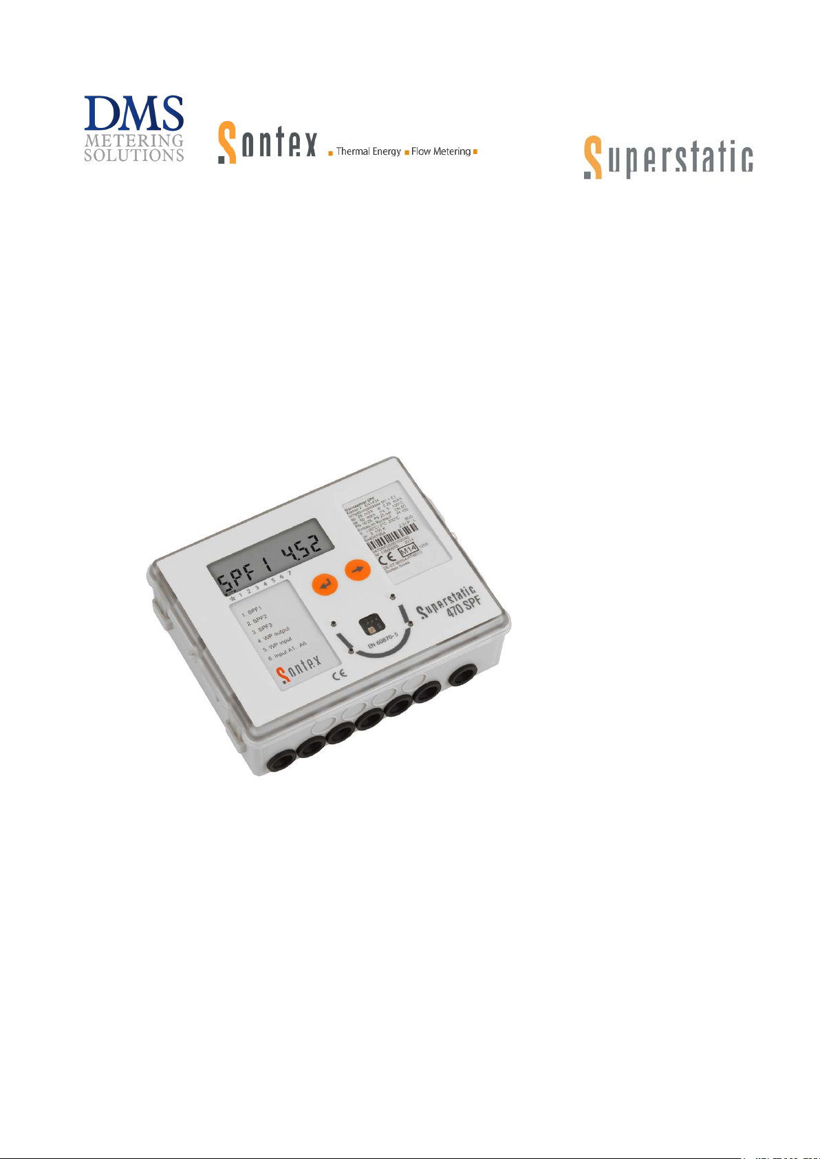
Superstatic 470/479 SPF
Edition:
Document:
Manufacturer:
Local Agent:
Rev. 02-03-2015
0470P004
Manual Superstatic 470 SPF 02-03-2015
Sontex SA
DMS Metering Solutions X-Cel House
Chrysalis Way Langley Bridge
Eastwood NG16 3RY
Tel.: 01773 534555 Fax: 01773 534666
Email: [email protected]
Web: www.dmsltd.com
Page 2

Revision
Edition
Date
Author
Description
14-11-2013
14.11.13
SV
Document written
08-01-2014
08.01.14
SV
SPF Modification, Main display with energy
10-01-2014
10.01.14
SV
Images of modification
02-12-2014
02.12.14
SV
Update
19-01-2015
19.01.15
SV
Update display sequences
17-02-2015
17.02.15
SV
Update layout
18-02-2015
18.02.15
SV
Update layout
20-02-2015
20.02.15
SV
Update data
02-03-2015
02.03.15
SV
Finalizing document
0470P004 Manual Superstatic 470 SPF 02-03-2015 2
Page 3

Contents
1. General................................................................................................................... 4
1.1 Introduction ............................................................................................................. 4
1.2 Application area of Superstatic 470/479 ................................................................. 4
2. Instructions for installation .................................................................................. 5
2.1 Communication interface ........................................................................................ 5
2.2 Safety notes ............................................................................................................ 5
2.3 Recognition of the heat pump module .................................................................... 5
2.3.1 Recognition of the heat pump module with the SW Prog470/479 ....................................... 5
2.4 Differences between SPF 1, SPF 2, SPF 3 ............................................................... 6
3. Functional description.......................................................................................... 7
3.1 Supply and safety ................................................................................................... 7
3.1.1 Power supply modules ....................................................................................................... 7
3.1.2 Safety instructions ............................................................................................................. 7
3.2 Cable connections .................................................................................................. 8
3.2.1 Main connection board of the computing unit ..................................................................... 8
3.2.2 Heat pump Module ............................................................................................................ 8
3.3 Error messages ....................................................................................................... 9
3.3.1 List of error messages ....................................................................................................... 9
4. Use of the Superstatic 470/479 .......................................................................... 10
4.1 Communication protoc ol ....................................................................................... 10
4.1.1 Prog470/Prog479 ............................................................................................................. 10
4.1.2 Read/write concept via an optical interface ...................................................................... 10
4.2 Display .................................................................................................................. 10
4.2.1 Main display ..................................................................................................................... 11
4.2.2 Display sequence ............................................................................................................ 11
5. Software Prog470 / Prog479 ............................................................................... 13
5.1 Operating instructions Prog470 / Prog479 ............................................................ 13
5.1.1 Introduction ...................................................................................................................... 13
5.1.2 Installation ....................................................................................................................... 13
5.1.3 Prog470/Prog479 software functions ............................................................................... 13
5.1.4 System requirements ....................................................................................................... 13
5.1.5 Operating instructions for Prog470/Prog479 software ...................................................... 14
5.1.6 “Communication” tab ....................................................................................................... 14
5.1.7 “Modules” tab ................................................................................................................... 15
0470P004 Manual Superstatic 470 SPF 02-03-2015 3
Page 4
1. General
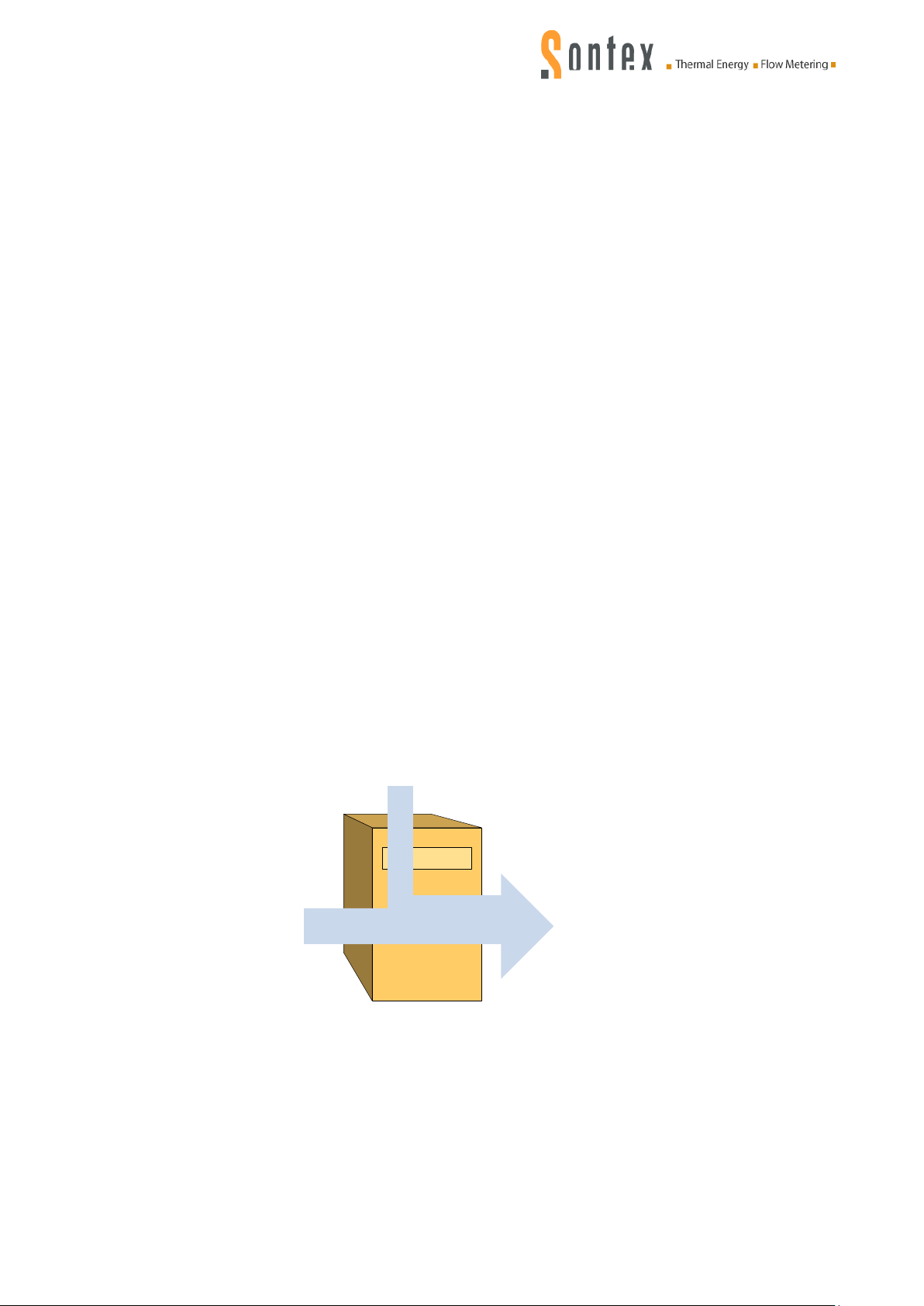
Environmental heat
Electric energy
Heat pump
Useful energy
and hot water
1.1 Introduction
This instruction describes the operation and installation of the Superstatic 470 SPF and 479 SPF,
together with the technical data and specifications for the Superstatic 470/479 SPF.
The static flow sensor and the computing unit may only be operated within the range of conditions
shown on the rating plate and in the technical specification. In the event of failure to comply with
these criteria, all liability of the manufacturer is excluded.
Seals may only be removed by authorised persons, if at all. If these conditions are not respected
the works guarantee expires and the manufacturer is no longer liable for calibration.
The cable between the flow sensor and the computing unit, together with the cable for the
temperature sensors, may not be shortened or modified in any way whatever.
N
otes on installation of the meter:
Comply with conditions of use as defined in Directive 2004/22/EC (MID) and correct
installation positions
For further information about the installation instructions for the Superstatic 470/479, see document
entitled “Installation guidelines Static Heat Meter Superstatic 440/449”.
1.2 Application area of Superstatic 470/479
The Superstatic 470/479 enables the Seasonal Performance Factor (SPF) of a heat pump to be
measured and its power determined. The performance factor is equivalent to the ratio between the
delivered heat capacity or useful energy and the electrical energy absorbed during a given lapse of
time. The measured values for the performance factors are shown on the Superstatic 470/479
display and can be read out via the M-Bus Communication Interface incorporated into the heat
pump-module.
0470P004 Manual Superstatic 470 SPF 02-03-2015 4
Page 5
2. Instructions for installation
Heat pump module
2.1 Communication interface
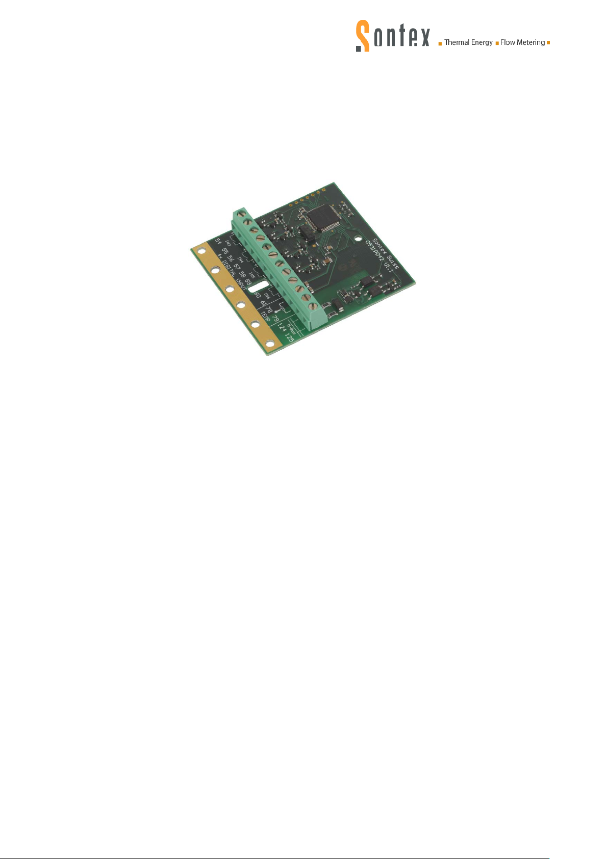
The Superstatic 470/479 contains a heat pump-Module, i.e. an additional double module with an
M-Bus output, four configurable non-galvanically separated digital inputs and a temperature
sensor input (not operational at present).
The main connection board of the computer unit has two additional inputs.
2.2 Safety notes
Before using the Superstatic 470/479, avoid electrostatic discharges during fitting or use. Before
touching the computing unit or the heat pump module, you are advised to touch an earthing source
(e.g. a water pipe or a hot water pipe) to effect an electrical discharge from your own person.
2.3 Recognition of the heat pump module
By means of the Prog470/Prog479 software the configuration of the Superstatic 470/479 and the
parameterisation of the inputs used for calculation of t he performance factors can be detect ed and
displayed.
2.3.1 Recognition of the heat pum p module with the SW Prog470/479
The Prog470/479 software allows the recognition of the heat pump module and provides the
following informatio n :
Firmware version of the heat pump module
Configuration of the M-Bus interface
Configuration of the four digital inputs
f the software has detected the heat pump module, the following parameters can be configured:
I
M-Bus interface:
Transmission speed
Primary address
Identification number
Reaction time
Parity
Digital inputs:
Counting type: deactivated/pulse counting/Operating time counting/Time factor for each
digital input
Determination of the units
Pulse factor value
0470P004 Manual Superstatic 470 SPF 02-03-2015 5
Page 6
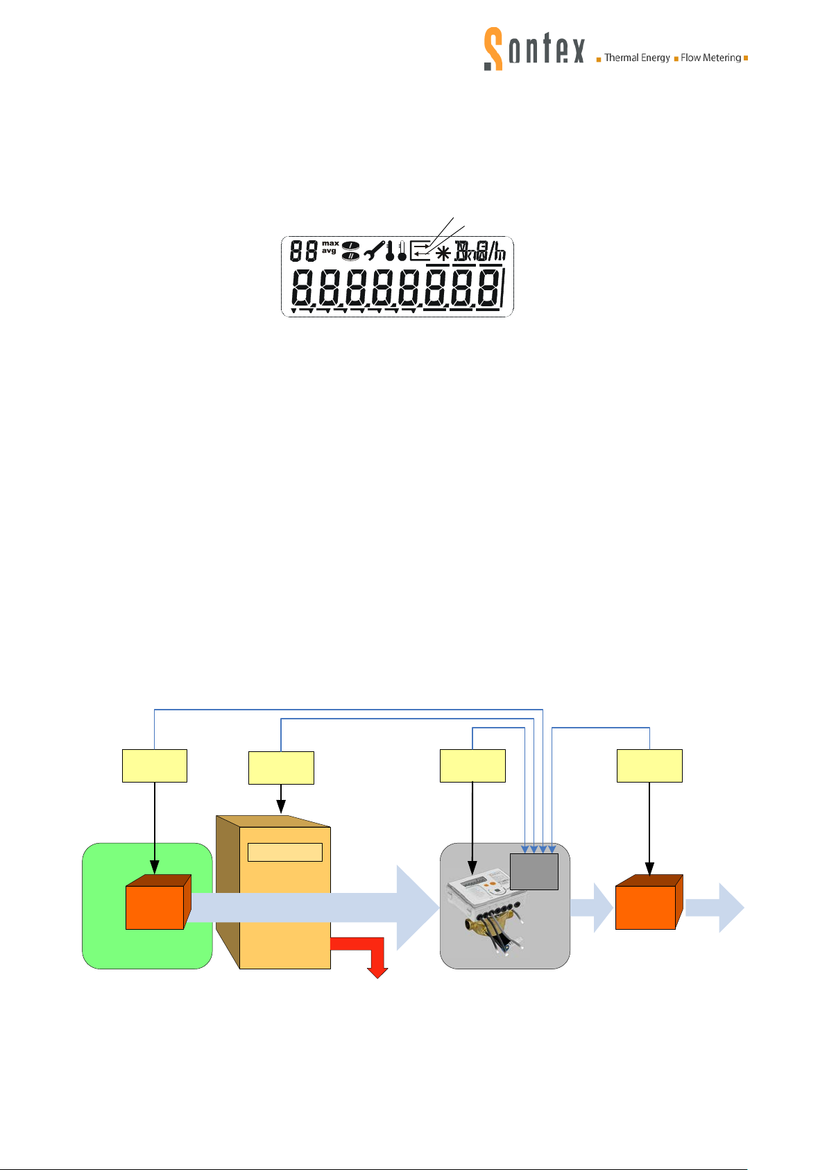
All the parameterization and read -out functions of the Superstatic 470/479 computing unit are
Environmental heat
Heat pump
Useful energy
and hot water
Umwälz-
pumpe
Circulating
pump
Losses
Electric
meter
Electric
meter
Electric
meter
Electric
meter
Digital
inputs
PAC
Module
Superstatic 470/479
1 2 3 4 5 6 7
Communication sortante
Communication entrante
identical to the functions of the Supercal 531/ Prog531 computing unit.
Note: The Firmware version of the Superstatic 470/479 computing unit must be higher than
V10.0.0.0.
he arrows on the LCD display symbolize the outgoing/incoming communication.
T
2.4 Differences between SPF1, SPF2, SPF3
Three different performance factors can be measured and displayed using the Superstatic
470/479.
he SPF1 value displays the performance factor of the heat pump over a particular period of time.
T
The SPF1 can be equated with a seasonal performance factor (COPA). The value of the previous
period is stored and can be displayed.
The value SPF2 shows the performance factor of the heat pump since its initial commissioning.
The SPF2 is never reset.
he SPF3 value shows the performance factor of the heat pump in an event period of one day.
T
The SPF3 is reset daily at midnight. An overview of the past 31 days can be shown on the display.
E
ach current meter of the heat pump can be connected to the heat pump module to enable the
electrical energy absorbed by the whole facility to be determined.
Example of configuration:
0470P004 Manual Superstatic 470 SPF 02-03-2015 6
Page 7

3. Functional de scription
3.1 Supply and safety
The Superstatic 470/479 must be operated with a mains power voltage of 230/90 VAC or 24 V
AC/DC.
A battery supply is not permitted.
Please respect the following notes.
3.1.1 Power supply modules
The mains power module 230/90 VAC – 45/60 Hz is to be protected by an (inert) 1AT fuse.
lectrical connection of the power supply modules
E
The electrical connection is to be established by a qualified person in compliance with the valid
standards and having regard to local safety requirements. The mains power line is to be laid in
such a way that no hot parts (pipes etc. above 80 °C) may damage its insulation. The electrical
connections must not come into contact with water.
3.1.2 Safety instructions
The Superstatic 470/479 has been manufactured and tested in compliance with safety standard
EN60950 and was perfectly safe at the time of dispatch from the factory. To maintain that condition
and ensure safe operation of the appliance the user must comply with the instructions set out in
this document. When opening covers or removing components parts which carry voltage may be
exposed. All interventions and repairs must therefore be performed by a specially trained and
authorised professional. If the housing and/or the connection cable are damaged the power supply
module must be disconnected and secured against accidental re-starting. In general, an installation
situation with above average heat accumulation must be avoided. Above average heat
accumulation is prejudicial to the service life of the electronic components.
For protection against damage and dirt, the packaging should not be removed until immediately
before installation.
For cleaning purposes use only a cloth moistened with water. Do not use cleaning fluids or
solvents.
The connection cables must not be secured to the pipe and under no circumstances may they be
insulated.
0470P004 Manual Superstatic 470 SPF 02-03-2015 7
Page 8
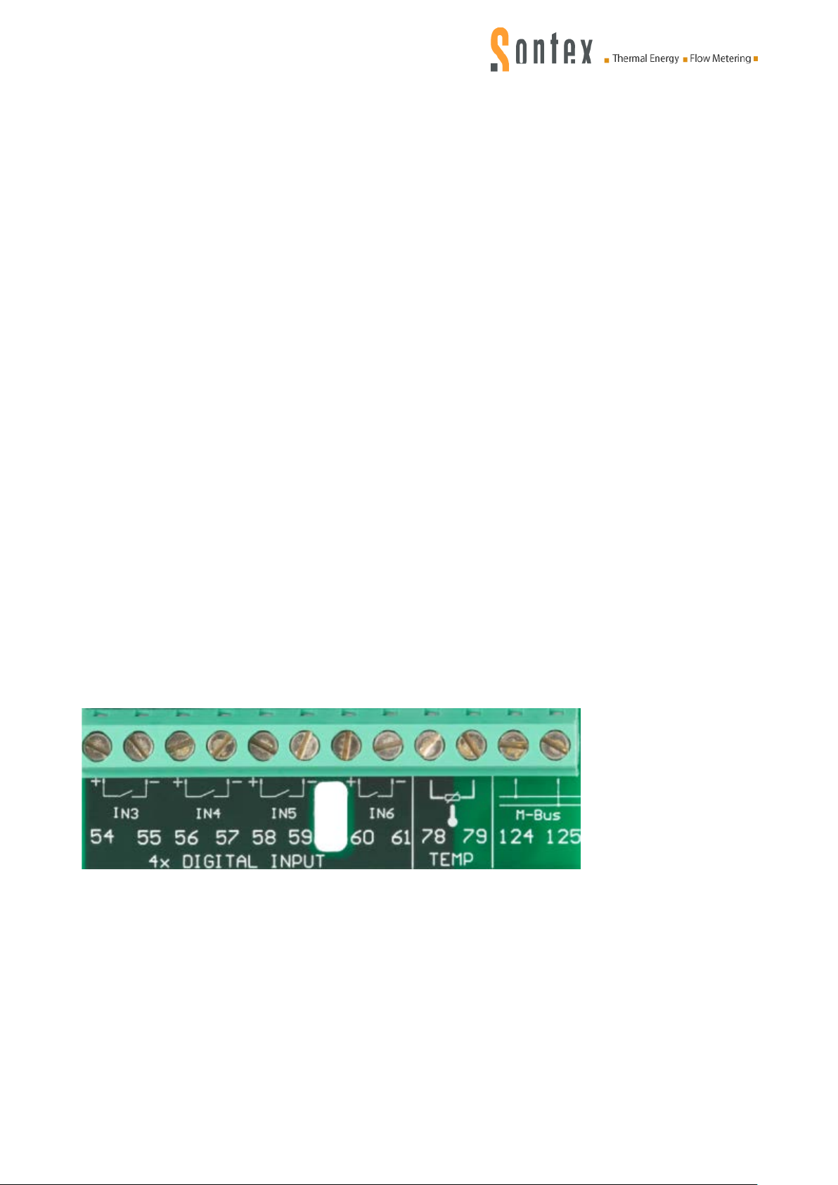
1,2
Hot temperature sensor, twin conductor technology
1,2 and 5,6
Heat sensor, four conductor technology
3,4
Hot temperature sensor, twin conductor technology
3,4 and 7,8
Hot sensor, four conductor technology
10
(+) pulse input flow sensor 440/449 (white cable)
11
(-) pulse input flow sensor 440/449 (green cable)
9
(3.6 V) supply flow sensor 440/449 (brown cable)
50
(+) pulse input, additional meter 1
51
(-) pulse input, additional meter 1
52
(+) pulse input, additional meter 2
53
(-) pulse input, additional meter 2
16
(+) Open-Collector-Output 1
17
(-) Open-Collector-Outputs 1 + 2
18
(+) Open-Collector-Output 2
24
M-Bus (module fitted ex-works), connect nothing on top!
25
M-Bus (module fitted ex-works), connect nothing on top!
124,125
M-Bus
54,55
(+,-) pulse input, additional meter IN3
56,57
(+,-) pulse input, additional meter IN4
58,59
(+,-) pulse input, additional meter IN5
60,61
(+,-) pulse input, additional meter IN6
78,79
Temperature sensor optional
3.2 Cable connections
Before connecting, remove the upper part of the computing unit. Effect the connections as follows:
3.2.1 Main connection board of the com put ing unit
Terminal Type of connection
3.2.2 Heat pump Module
Terminal Type of connection
Important: the screened cables must generally be earthed with the tension relief
Earthing
Make sure that all the earthing connection points (external power supply) of the system are
equipotential.
Voltage supply modules
The voltage supply module is connected by means of a cable to the main connection board of the
Superstatic 470/479 computing unit.
0470P004 Manual Superstatic 470 SPF 02-03-2015 8
Page 9
3.3 Error messages
The Superstatic 470/479 com puting unit displays a fault message by means of the three letter “Err”
and a code. If several codes occur simultaneously, the numbers of the fault reports are added
together:
if a fault occurs it is detected and displayed as long as it is present. When the fault disappears the
fault report is deleted and the normal display appears again.
3.3.1 List of error messages
Err1 The hot temperature sensor is open or short-circuited.
Err2 The cold temperature sensor is open or short-circuited.
The temperature sensors have been inverted or the temperature in the cold line is
higher than in the hot line.
Err4 Flow too high.
Err8 EEPROM fault in the upper part (relevant to the measurement)
(active only after the second time).
Err16 EEPROM error in the lower part (terminal strip)
(active only after the second time).
Err32 EEPROM configuration error in the upper part (relevant to the measurement).
Err64 EEPROM configuration error in the lower part (terminal strip)
Err128 Internal electronic fault, back to the manufacturer
Err256 Voltage failure (power supply module)
Err512 Defective module plug location 1
Err1024 Defective module plug location 2
Err2048 Flow error at additional input A1
Err4096 Flow error at additional input A2
Err8192 Internal electronic fault, back to the manufacturer
Crc err EEPROM configuration fault (from firmware V4.2)
Conf err Incoherent configuration (from firmware V4.2)
If a fault continues for more than one hour, it is recorded in the fault memory (EEPROM) with the
date and time (start of fault) and duration (in minutes).
If a fault lasts for less than 60 minutes, it is automatically deleted without being memorised.
The fault reports disappear automatically from the display 60 seconds after the fault has ended.
Note on disposal
The Superstatic 470/479 must be discarded in an environmentally-friendly way or returned to the
manufacturer for disposal. Our components are then compliant with the criteria governing
electronic waste. If you effect disposal yourself please enquire about recycling possibilities in your
particular region.
0470P004 Manual Superstatic 470 SPF 02-03-2015 9
Page 10
SPF 2 4.20
Performance
factor SPF2
Heat energy
emitted
E0
129
.
63
Electrical energy
absorbed
129
.
63
00000063
a1
Digital input
configuration
Performance
factor SPF3
SPF 3 4.31
Performance
factor SPF1
SPF 1 4. 25
Cumulated
energy
.1253.925
Ei
4. Us e of the Superstat ic 470/479
4.1 Communication protocol
For communication purposes, the Superstatic 470/479 uses the M-Bus Protocol compliant with
European standard EN13757-3.
The M-Bus Protocol supports a primary and a secondary address. For further information see MBus documentation or the following internet site:
http://www.m-bus.com/
4.1.1 Prog470/Prog479
The Superstatic 470/479 can be configured with the Prog470/Prog479 software.
Prog470/Prog479 software may only be used by authorised persons. The software permits
communication with the Superstatic via an optical communication interface or an M-Bus interface.
By means of this software, the various digital inputs can be configured and parameterized
depending on the desired SPF type.
For further information about the Prog470/Prog479 software, see Chapter 5.1 of this manual.
4.1.2 Read/write concept via an optical interface
Using a standardised optical head, the configuration data of the Superstatic 470/479 computing
unit can be transferred directly to the Prog470/Prog479 software on a PC or vice versa.
4.2 Display
LCD operating concept
The navigation key enables the different menus or menu positions to be addressed.
When inputting a number in the test mode, the numbers can be increased from 0 to 9 with
this key.
Selection or confirmation key of the menu, position or entered number.
By simultaneous actuation of both keys, the display reverts to the first position of the selected
menu or if the cursor is already in the first position, the cursor will be positioned in the 1
the LCD display.
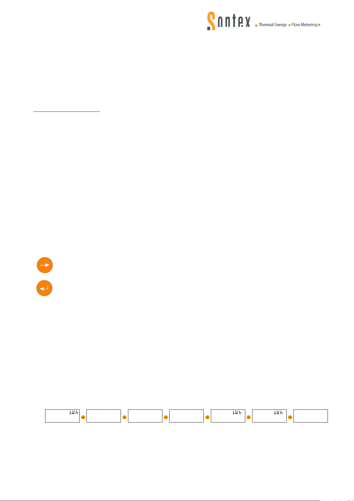
The Superstatic 470/479 has the following menus:
See label below the LCD display
Performance factor SPF1
Performance factor SPF2
Performance factor SPF3
Heat energy emitted
Electrical energy absorbed
Digital input configuration
st
menu of
0470P004 Manual Superstatic 470 SPF 02-03-2015 10
Page 11
.1253.925
SPF 2 4. 20
Performance factor SPF2
Performance factor SPF1
01
SPF 1 4..25
Of
DA
01.01.2014
DA
On
01.01.2013
SPF 1 4. 25
Performance factor SPF3
02
SPF 3 4. 27
SPF 3 4.31
01
SPF 3 4. 27
31
SPF 3 4. 27
Current day
Current day -1
Current day -2
Current day -31
4.2.1 Main display
The 1st display menu of the Superstatic 470/479 corresponds to the main display.
The main display contains the energy value.
When commissioning or upon simultaneous actuation of the two keys, the main display of the
Superstatic 470/479 appears automatically. This applies from any desired initial menu.
If a fault occurs, it is detected and shown in the first position on the display as long as it is present.
When the fault disappears, the fault report is deleted from the display.
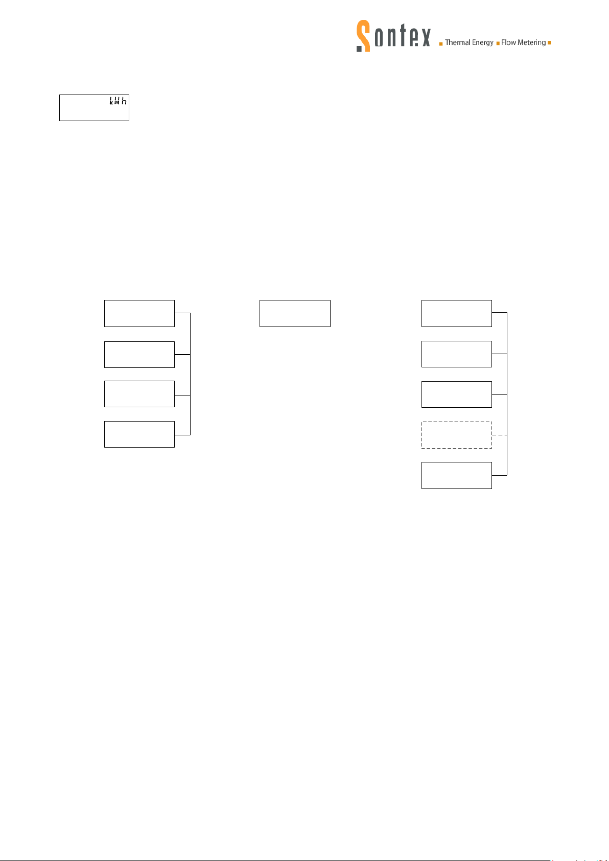
4.2.2 Display sequence
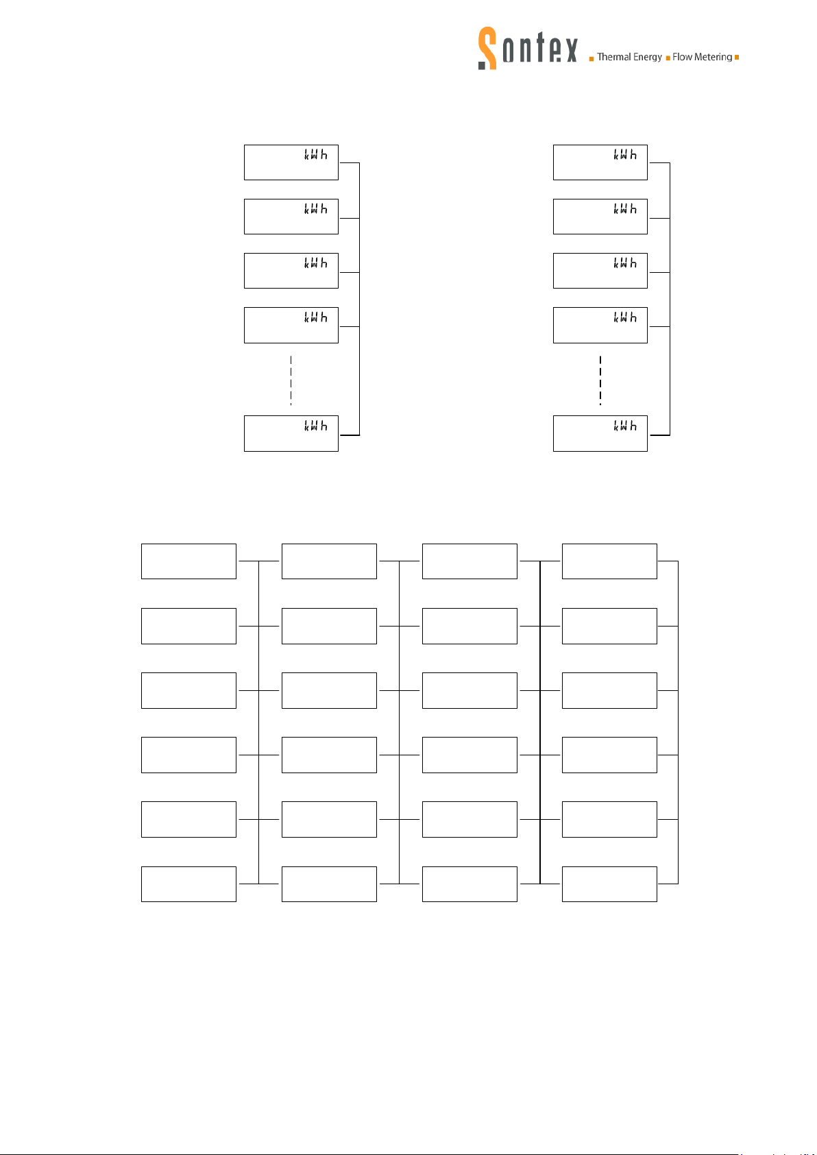
The following display sequences can be shown on the LCD display:
Performance factor SPF1, SPF2 and SPF3
0470P004 Manual Superstatic 470 SPF 02-03-2015 11
Page 12
Electrical energy absorbed
31
12
8.58
Ei
03
128
.
58
Ei
02
12
8.58
Ei
01
128.58
Ei
129.63
Ei
Cumulated energy
Last monthly value
energy
Energy month-2
Energy month-
3
Energy month-
31
Heat energy emitted
31
E
0
12
8.58
03
E0
128
.
58
02
E
0
12
8
.
58
01
E0
12
8
.
58
E0
129.63
Cumulated energy
Last monthly value
energy
Energy month
-2
Energy month-
3
Energy month-
31
Digital input Pulse factor Unit Tipe
00000063
a1
a1
W
h
1
00000063
a2
a2
W
h
1
00000063
a3
1.000
a3
M
n
00000000
a4
1
a4
00000000
a5
a5
W
h
1
00000000
a6
a6
off
a6 W
h
1
a5
Const if
a4
state if
a3
timE if
a2
Pulse if
a1
Pulse if
1.0000
a6
U /i
n
1.0000
a5
U /i
n
1.0000
a4
U /i
n
1.0000
a3
U /i
n
1.0000
a2
U /i
n
1.0000
a1
U /i
n
Heat energy and electrical energy:
Configuration of the digital inputs:
Pulse IF : Used with input « Binary counting ».
Time I F : Used with input « Time counting ».
State IF : Not used presently.
Const IF : Used with input « Amount counting ».
OFF : Input disabled.
0470P004 Manual Superstatic 470 SPF 02-03-2015 12
Page 13

5. Software Prog 470 / Prog479
5.1 Operating instructions Prog470 / Prog479
5.1.1 Introduction
The Prog470/Prog479 software permits programming and read-out for the Superstatic 470/479.
The installation instructions for the Supercal 531 computing unit and the installation instructions for
the Prog531 software remain valid for most functions. The change from the Supercal 531 consists
in the fact that the Heat pump module is an integral part of the Superstatic 470/479. When the
module is detected by the Prog470/Prog479 software, the “SPF Module” tab is added. The
configuration of the digital inputs is effected in this tab.
The following chapters provide important information about installation and use of the Prog470/
Prog479 software and about the parameterization of the different inputs which are used to
calculate the various performance factors (SPF1, SPF2 und SPF3).
5.1.2 Installation
The Prog470/Prog479 software is supplied by Sontex SA by e-mail or can be downloaded from
http://www.sontex.ch/downloads_e.html.
The data file must be downloaded into a folder on your PC (e.g. in C: \ Sontex \ Prog470\ Vx.xxx).
Make sure that none of the data files contained in this folder are write-protected. If some data files
are write-protected the characteristics of the data files must be altered (via Windows Explorer).
If the Prog470/Prog479 software is updated all the data files of the old version must be replaced by
the new release.
5.1.3 Prog470/Prog479 software functions
The Prog470/Prog479 software provides the following functions:
Configuration of the digital inputs of the SPF module.
Read-out of the SPF1, SPF2 and SPF3 factor values.
All other parameterization and read-out functions of the Superstatic 470/479 computing unit are
identical to the functions of the Supercal 531/Prog531 computing unit.
5.1.4 System requirements
The following equipment is needed for correct operation of the Prog470/Prog479 software:
PC Pentium II or higher (400 MHz or faster
O
perating system: Windows 2000/XP or higher
10 MB free memory space on the hard disc
256 MB RAM memory
Internet Explorer V6.0 or higher installed on the PC
)
0470P004 Manual Superstatic 470 SPF 02-03-2015 13
Page 14
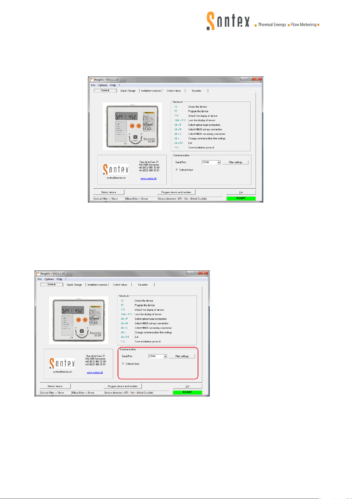
5.1.5 Operating instructions f or Prog470/Prog479 software
Fig. 1: Main display
Fig. 2: Communication interface
Start the software with the Prog470.exe/Prog479.exe data file:
One of three tabs can be chosen in the main menu of the Prog470.exe/Prog479.exe software. The
choice of tab is carried out by clicking on the corresponding key in the main window:
5.1.6 “Communication” tab
Communication between the Prog470/749 software and the Superstatic 470 computing unit is
possible only by means of the read-out head or by a serial cable (RS232) via the M-Bus protocol.
The M-Bus protocol is used on the basis of European standard EN13757-3 for communication
between the software and the computing unit.
Select the communication interface
in the window: “Communication
with the Superstatic 470/479
computing unit”.
For communication via the
optical or serial interface
between the Prog470/Prog479
software and the computing unit,
the upper cover of the
computing unit must be located
above the lower part. The
computing unit 470/479 must be
closed.
f communication problems are experienced the filter settings must be altered as follows:
I
0470P004 Manual Superstatic 470 SPF 02-03-2015 14
Page 15
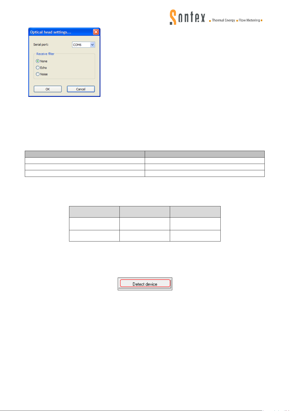
Check whether the correct COM-Port has been selected.
Attempt communication again with the new setting
If detection fails, use a different read-out head or PC.
Read-out head
Filter setting
P+E Technology: “K1-98” or “K1-06”
Without filter
P+E Technology: “K01-USB”
Without filter
Siemens
Echo
M-Bus (above
RS232)
Fig 4: Detect device
Select the “Without filter” setting as standard for the read-
out head.
Depending on the read-out head type the signal must be
filtered for successful communication.
Close the window and attempt communication with the
new setting again.
If detection fails:
Set the filter to “ Echo”:
Attempt communication again with the new setting.
If detection fails:
Fig. 3: Filter settings
Set the filter to “Noise”.
5.1.6.1 Known configuration of certain read-out heads
The read-out heads listed below function with the indicated filter settings with Prog470/Prog479
software impeccably:
5.1.6.2 Standard communication parameters
The transmission speed of the communication interfaces is defined by the following parameters:
Interface Speed [Baud] Parity
9600 straight
Optical 9600 straight
5.1.6.3 Reading the configuration of the Superstatic 470/479 computing unit
When conf iguration of the communication interface has been terminated, actuate the “Detect
device” key in order to read the configuration of the computing unit 470/479:
5.1.7 “Modules” tab
As soon as the computing unit has been read by the software Prog470/Prog479, select the
“Modules” tab and detect the SPF module. The configuration parameters are displayed in the
“Modules” tab of the Prog470/Prog479 software.
0470P004 Manual Superstatic 470 SPF 02-03-2015 15
Page 16
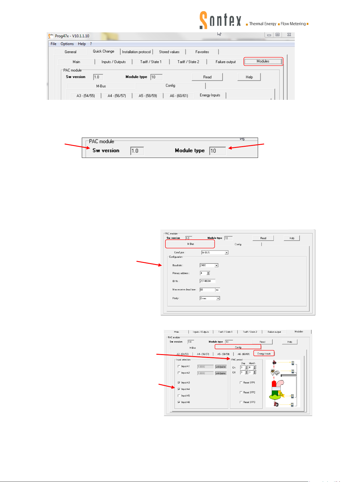
Fig. 5: Module tab
Firmware
Type of
Fig. 6: Firmware version
M-Bus communication interface
Parameterization of the SPF-Module inputs
The firmware version and the type of module are displayed:
version
module
5.1.7.1 Display/Change of digital inputs
The SPF module consists of two different parts:
The following equipment is needed for correct operation of the Prog470/Prog479 software:
M-Bus communication interface
Digital inputs
Standard M-Bus communication
interface configuration
Transmission speed
Primary address
Possibility of connecting a modem.
“SPF period” is the period for which the
performance factor SPF1 is calculated.
Here: 3.4. to 3.3. of the following year.
“SPF Input” contains the inputs used in
the SPF function (sum of electrical
energies). Here: sum of inputs A3, A4
and A6.
0470P004 Manual Superstatic 470 SPF 02-03-2015 16
Page 17
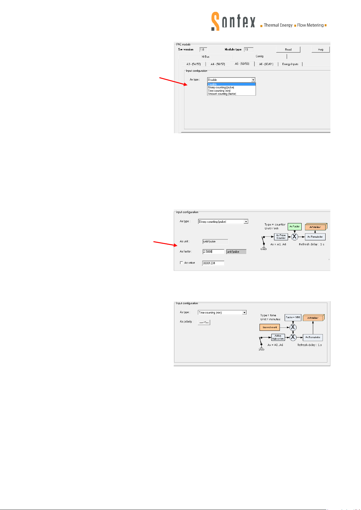
Type of counting:
Various counting types are possible for the
Binary counting : pulse counting.
Time counting : counting the operating
inputs A3-A6:
Disable: counting deactivated.
Binary counting: pulse counting.
Time counting: counting t
ating time.
oper
he
Amount counting: time factor for
each digital input.
he Medium and ID are defined: e.g. for A3 ID 3 applies and for A6 ID 6. The Medium is always
T
set to “Water”.
The speed is automatically adjusted depending on the chosen counting type:
Binary counting = Fast.
Time counting; Amount counting= Slow.
The work unit must be the Wh.
The pulse factor « Ax factor » must be
defined according to the unit Wh.
The initial value « Ax value »
c
orresponds to the starting value of t
ectricity meter. This value allows t
el
ompare the evolution of both meters,
c
he
o
electricity and SPF.
time.
This function allows to know the
dur
ation operating time of the heat
pump. The unit used is the minute.
This value is independent of t
electrical energy consumed by the
ing pump.
heat
The counting can be by open or clos
contact.
he
e
0470P004 Manual Superstatic 470 SPF 02-03-2015 17
Page 18
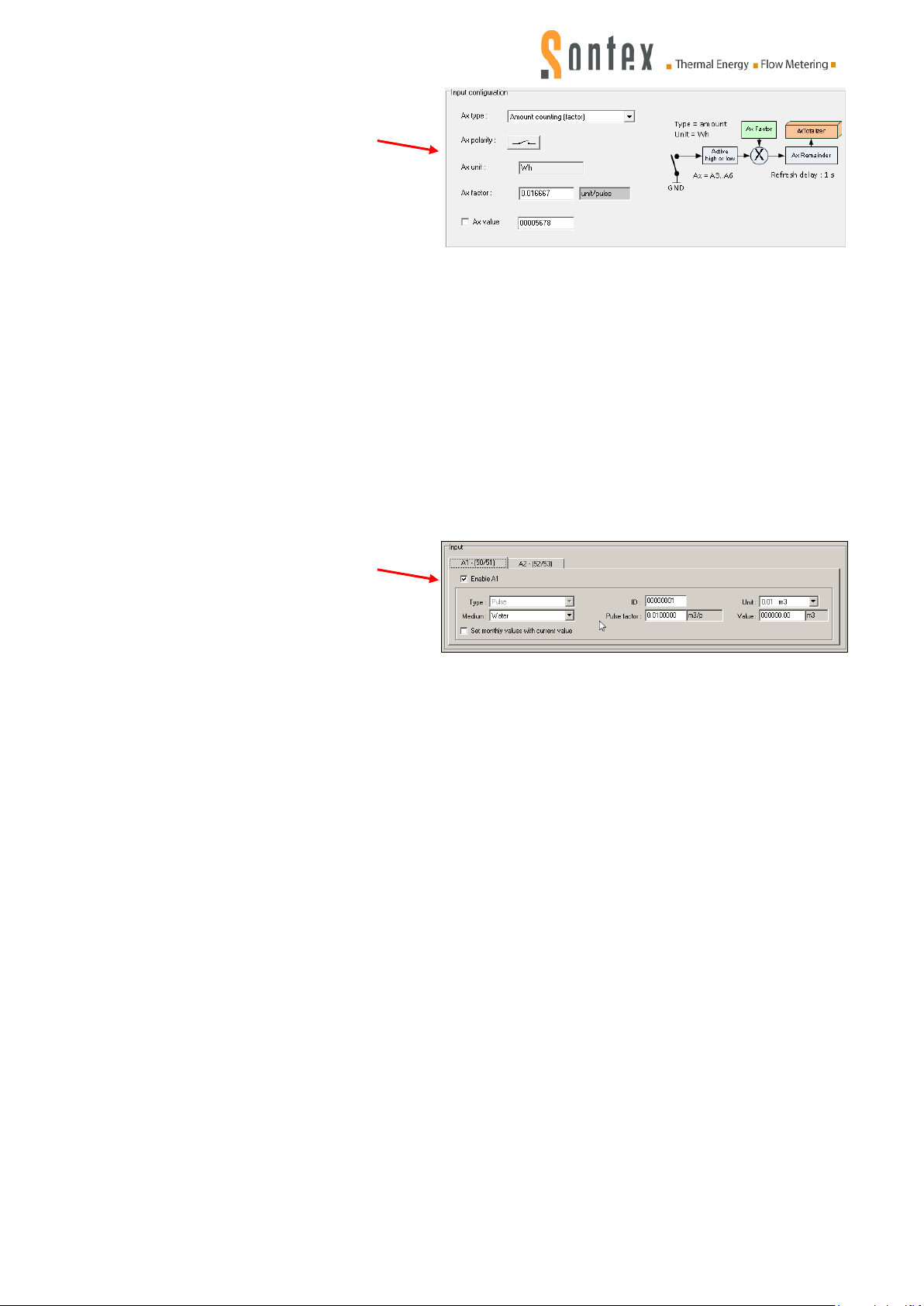
Amount counting : time factor for each
digital input.
Inputs A1 and A2
The electrical device is not connected
to an electricity meter.
In this case, knowing the electrica
l
power of this device, it is possible to
integrate its power over the time or to
define in Wh the consumption of
electrical energy.
The pulse factor « Ax factor » must be
defined according to the unit Wh.
Example: A pump of 400W switched
ing 1 hour consumes an electrical
dur
on
energy of 400Wh.
The factor (Ax factor) will be configure
ith 400 [Wh]/3600 [sec] = 0.111.
w
The counting can be by open or close
c
ontact.
d
Inputs A1-A2 only allow “Binary
Counting” and are controlled under the
menu point “Inputs/Outputs”.
The inputs can be configured in the
l
ong (<=5 Hz) or fast (>5 Hz) mode.
0470P004 Manual Superstatic 470 SPF 02-03-2015 18
Page 19

Notes
0470P004 Manual Superstatic 470 SPF 02-03-2015 19
Page 20
T
echnical Support
For technical support, please contact the local Sontex representations or Sontex SA directly.
ontex hotline:
S
[email protected], +41 32 488 30 04
0470P
0470P004 Manual Superstatic 470 SPF 02-03-2015 20
004 Manual Superstatic 470 SPF 02-03-2015 Sontex SA 2013
 Loading...