

Page 1

Wireless Probe Type
Ultrasound Scanner
CProbe
User's Guide
Prescription Statement “Caution: Federal law restricts this device to sale by or on
the order of a physician”.
A/0
Page 2

目录
Section 1 INTRODUCTION...................................................................................................................... 1
1.1 Signs and Meaning
1.2 TECHNICAL PARAMETERS
1.3 INDICATIONS FOR USE
1.4PRECAUTIONS & WARNINGS
Section 2 GETTING STARTED.................................................................................................................. 1
2.1 UNPACKING
2.2 INSTALLING APP
2.3 STARTING PROBE
2.3.1 Visual inspection.......................................................................................................... 7
2.3.2 Probe cleaning................................................................................................................ 7
2.3.3 Boot check........................................................................................................................ 7
2.4 WIRELESS CONNECTION
Section 3 APP OPERATIONS................................................................................................................... 9
3.3.2 Patient information input........................................................................................................... 11
3.3.3 Data measurement......................................................................................................................12
3.3.4 Report download
3.3.5image and vedio storage
3.3.5.1 Image storage............................................................................................................ 15
3.3.5.2 Vedio storage............................................................................................................ 16
3.3.6 Image and vedio review
3.3.7Replace the signal channel
Section 4 MAINTEANCE........................................................................................................................ 17
4.1 PROBE CHARGING
4.2 WATERPROOF IPAD
4.3 CLEANING AND DISINFECTION
4.4 STORAGE
4.5TROUBLE SHOOTING
4.6Disposal
4.7Proudct maintenance and protection
Section 5 Safety.................................................................................................................................... 20
5.1 Safety Instructions
5.1.2Mechanical Safety................................................................................................................ 20
5.1.3 Accessories Safety............................................................................................................... 21
5.1.4 Cybersecurity....................................................................................................................... 21
5.2 Principles of Using Acoustic Power............................................................................................. 22
.......................................................................................................................................18
......................................................................................................................................... 18
........................................................................................................................ 1
.......................................................................................................... 2
................................................................................................................. 2
....................................................................................................... 2
.................................................................................................................................... 1
........................................................................................................................... 4
......................................................................................................................... 7
..............................................................................................................8
..................................................................................................................... 14
......................................................................................................... 15
......................................................................................................... 16
..................................................................................................... 16
.......................................................................................................................17
................................................................................................................... 17
................................................................................................. 18
...................................................................................................................18
..................................................................................... 19
......................................................................................................................20
Page 3

5.2.1 Biological Safety................................................................................................................. 22
5.2.2 Mechanical and Thermal Indices.........................................................................................22
5.2.3 Acoustic Output Statement.................................................................................................. 22
5.2.4 Operator Control Property................................................................................................... 23
5.2.5 Acoustic Power Settings...................................................................................................... 24
5.2.6 ALARA................................................................................................................................24
5.3 Electromagnetic Compatibilities................................................................................................. 24
5.3.1 Electromagnetic Emission................................................................................................... 25
5.3.2 Electromagnetic Immunity.................................................................................................. 26
5.3.3 Recommended Separation Distance.................................................................................... 27
Appendix A Specifications ....................................................................................................28
Appendix B Acoustic Output Data....................................................................................................... 29
Page 4
Section 1 INTRODUCTION
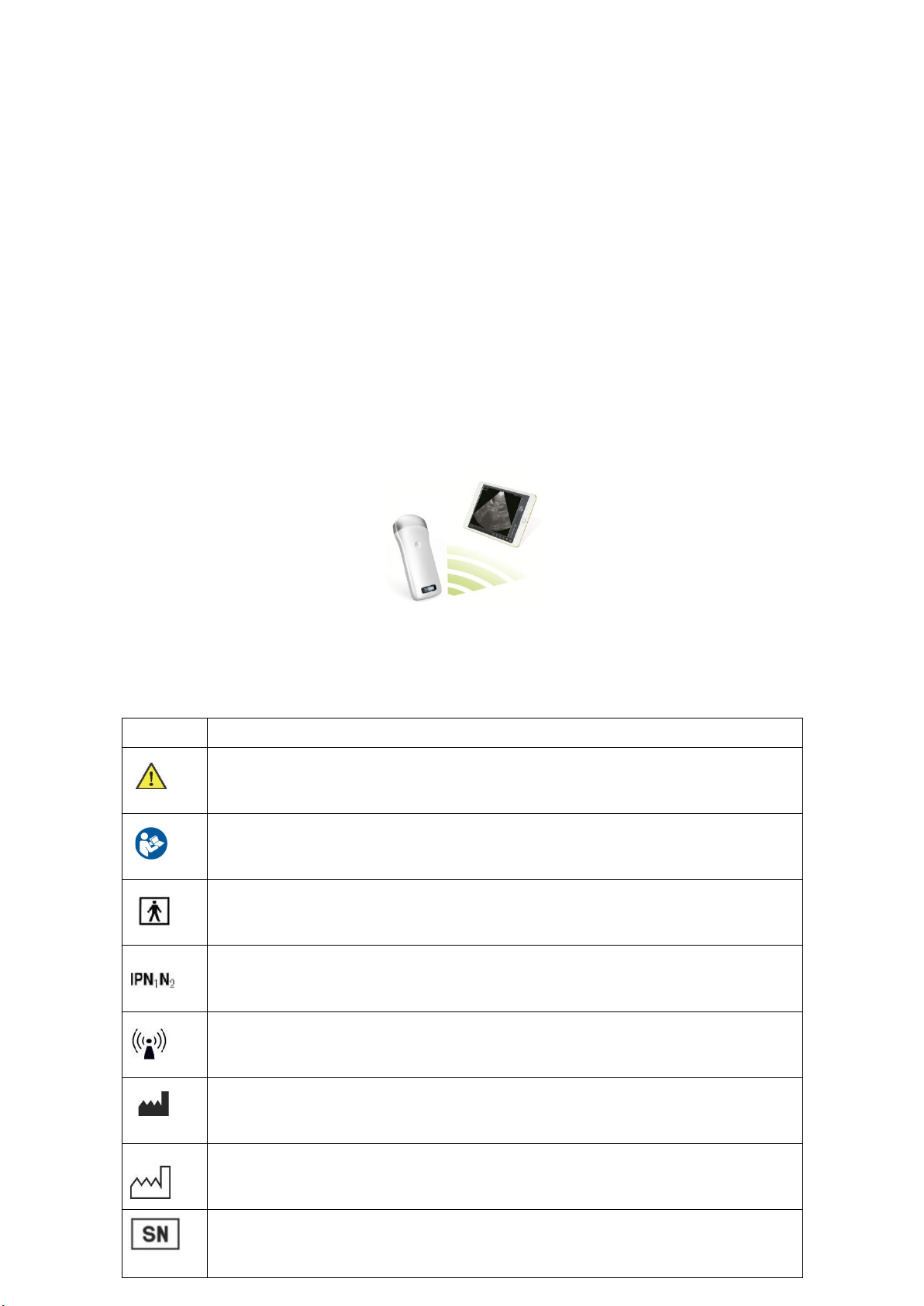
1.1 Signs and Meaning
Sign
Meaning
Caution! Please consult the accompanying document.
Consult the user manual
Type BF applied part
Degree of IP protection
Non-ionizing electromagnetic radiation
Manufacturer
Date of manufacture
Serial number
The Wireless Probe Type Ultrasound Scanner (Model: CProbe) is the new generation
instruments for ultrasonography with the outstanding feature of wireless.
Different with traditional ultrasound scanner with a cable connecting from probe to main unit,
no cable appears at the end of the probe of the Scanners. The probe of the Scanner is highly
integrated with ultrasound image processing, power management and a wireless signal provider to
be connected by the main unit.The main units different with traditional devices are now changed to
be any iPad from Apple Inc or Apple iPhone. The probe acts as a Wi-Fi Access Point and can be
connected by iPad or iPhone. With the probe be connected through WiFi and the App is running,
enjoy your days of working without the trouble making cables.
This manual is intended to provide a thorough overview of the Scanner and should be carefully
read before starting operating the device.
Thank you for your trust in us to provide for your ultrasonography needs.
Figure 1.1 CProbe Wireless Probe Type Ultrasound Scanner
1
Page 5

Keep dry
IPX5
Prevent the water from the nozzle from invading in all directions and cause damage to
the electrical apparatus.
1.2 TECHNICAL PARAMETERS
Display: iPad / iPhone Series
Operations
Storage and Transportation
Relative Humidity
25% to 80%,
non-condensi
ng
25% to 93%, non-condensing
Ambient Temperature
5°C to +40°C
-20°C to +55°C
Atmospheric Pressure
700hPa to
1060hPa
700hPa to 1060hPa
PRECAUTION 1: Read the user manual carefully before operating the device, be familiar with
PRECAUTION 2: The instrument must work in a clean environment, should avoid direct sunlight,
PRECAUTION 3: The device shall be operated in undisturbed conditions so as to avoid data
PRECAUTION 4: When there is wireless channel congestion, switch the channel (Refer to
PRECAUTION 5: Prescription Use. The device shall be operated by professional physicians.
PRECAUTION 6: The device shall be repaired by professional recognized by the manufacturer.
Gray Scale: 256 levels
Battery last: > 3 hours
Size: 104mm x 50mm x 22mm
Weight: ≈308g
Electronic:
Input:5Vd.c. 1A
Battery Capacity:modle(SNP-4200) 3.8Vd.c. 4200mAh
continuous working time: 2hour
Waterproof: IPX5
1.3 INDICATIONS FOR USE
The Wireless Probe Type Ultrasound Scanner (Model: CProbe) is intended for diagnostic ultrasound
echo imaging, measurement, and analysis of the human body for general clinical applications
including obstetrics (OB), gynecology (GY) and general (abdominal) imaging.
1.4PRECAUTIONS & WARNINGS
the equipment and operation procedures, and strictly implement; the company is not
responsible for the damage caused by the improper use of the machine and the resulting
potential adverse consequences;
extreme temperature changes, dust, near heat sources, high humidity places, do not place
anything on top of the instrument.
transmission interruption.
Section 3.6 SETTINGS), and then restart the probe.
2
Page 6

PREACUTION 7: The device does not have shelf life. Its expected use lifeis 10 years. After 10
years, though the device still works normally, it is recommended to have it checked by the
PRECAUTION 8: Useless components shall be disposed according to local regulations.
PRECAUTION 9: Be careful when holding the device, for the device is handheld, it may fall.
PRECAUTION 10: Pay attention: the words “Insufficient Storage Space” will appear on the
WARNING 1: The device is not explosion-proof. Do not use it in inflammable and explosive
WARNING 2: Instrument is not waterproof, do not spill water or other liquids on the
This device complies with part 15 of the FCC Rules. Operation is subject to the following two
Changes or Modifications not expressly approved by the party responsible could void the user’
This equipment has been tested and found to comply with the limits for a Class B digital device,
If this equipment does cause harmful interference to radio or television reception, which can be
The device has been evaluated to meet general RF exposure requirement
manufacturer.
interface to remind the user to clean up space when storage space will be insufficient.
environment (such as in the presence of anesthetic gas, oxygen or hydrogen,etc.);
instrument.
conditions: (1) this device may not cause harmful interference, and (2) this device must accept
any interference received, including interference that may cause undesired operation.
s authority to operate this device.
pursuant to Part 15 of the FCC Rules. These limits are designed to provide reasonable
protection against harmful interference in a residential installation. This equipment generates,
uses and can radiate radio frequency energy and, if not installed and used in accordance with
the instructions, may cause harmful interference to radio communications. However, there is
no guarantee that interference will not occur in a particular installation.
determined by turning the equipment off and on, the user is encouraged to try to correct the
interference by one or more of the following measures:
-- Reorient or relocate the receiving antenna.
-- Increase the separation between the equipment and receiver.
-- Connect the equipment into an outlet on a circuit different from that to which the receiver is
connected.
-- Consult the dealer or an experienced radio/TV technician for help.
3
Page 7
Section 2 GETTING STARTED
Caution
Too high ultrasonic intensity and / or long exposure time
may cause injury.
Please do not apply the probe of this machine to the scope
not covered in this manual.
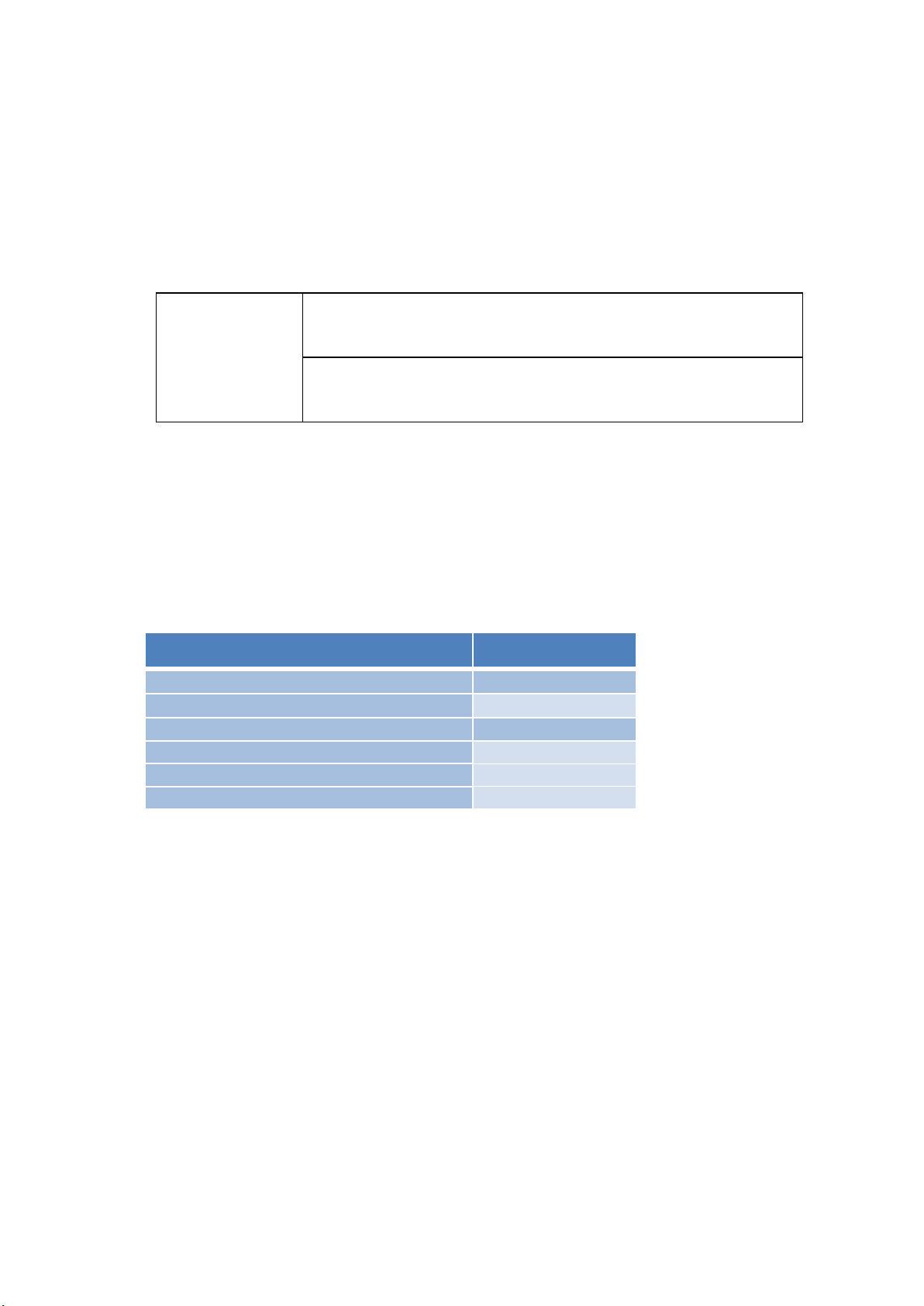
ITEMS
INCLUDED
Host(Including probe)
√
Manual
√
USB charging cable
√
Warranty Card
√
Power Adapter
Optional
Tablet
Optional
FOR YOUR PROTECTION, please read these safety instructions completely before applying
power to, or operating the system.
2.1 UNPACKING
The Scanner is carefully packed to prevent damage during shipment. Before unpacking, please
note any visible damage to the outside of the shipping containers.
Items should be checked in order to ensure that all ordered items have been received. The
following table lists the items which should be received with each particular system.
Table 2-1 Items List for The Wireless Ultrasound Scanner
Each item should be examined for any noticeable defects or damage that may have occurred
during shipment although it is packed carefully. If any defect or damage exists, please contact your
local representative immediately to report the problem.
1
Page 8
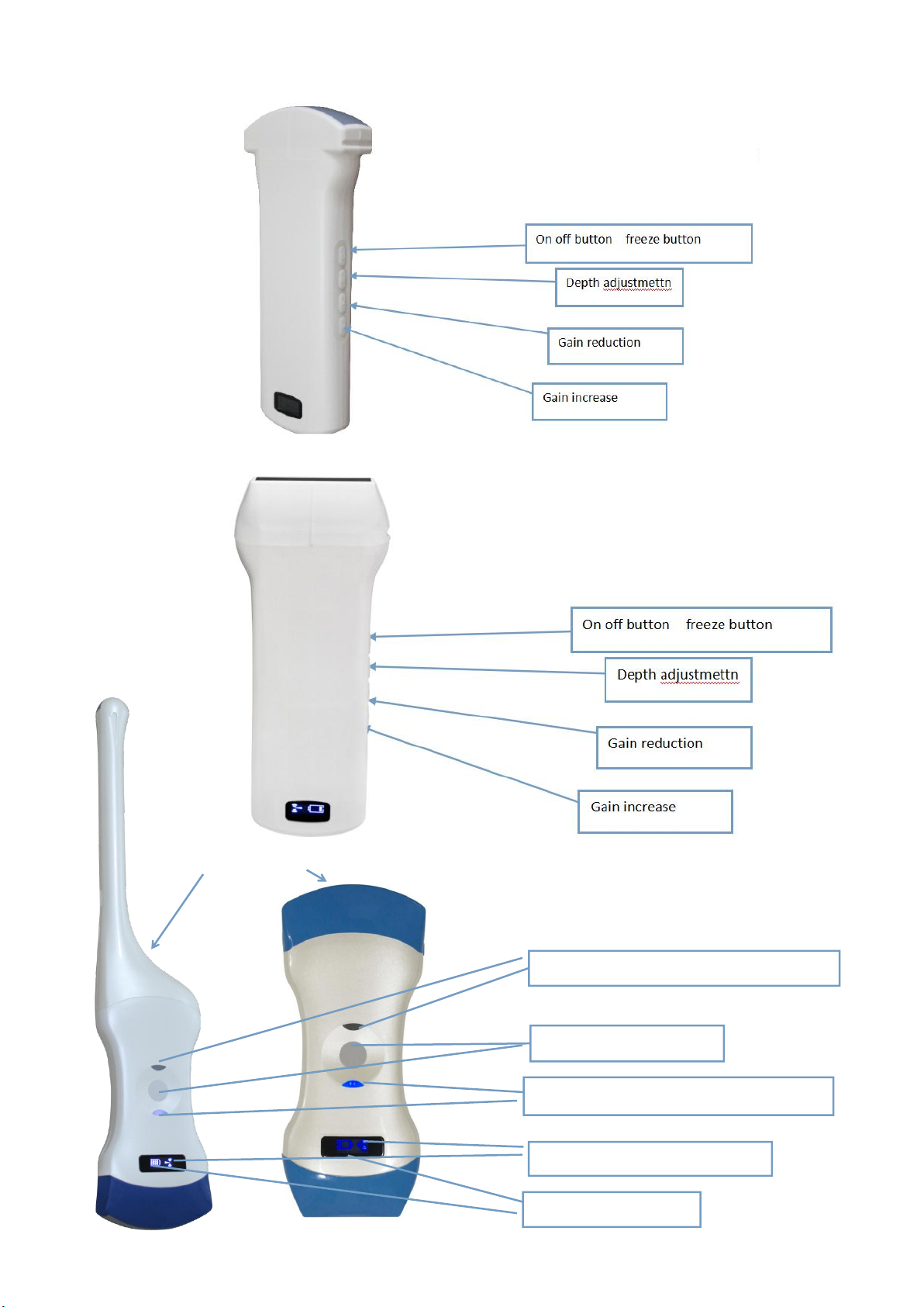
On Off/ freeze
Under probe working status display
Wireless signal status
Battery capacity
Upper probe working status display
Product schematic diagram
Wireless signal status display
Wireless signal status display
Probe
On Off/ freeze
Battery capacity
Probe
On Off/ freeze
Battery capacity
CT-probe CL-probe
Picture 2-1 L-probe
Picture 2-2 C-probe
Picture 2-3 double head
2
Page 9
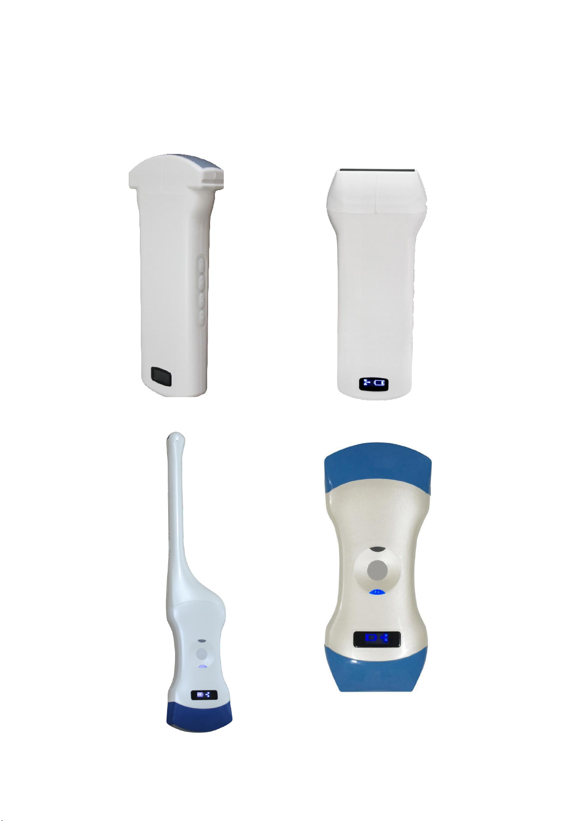
Switch the probe: press and hold the switch for three seconds
Working state display: indicator lamp indicates the position of the convex array to work
with the convex array probe, and indicator linear array position to work with the linear
array probe
Charging support: this probe only supports wireless charging.
Picture 2-4 C-probe&L-probe
Picture 2-5double head(CT-probe&CL-probe)
3
Page 10
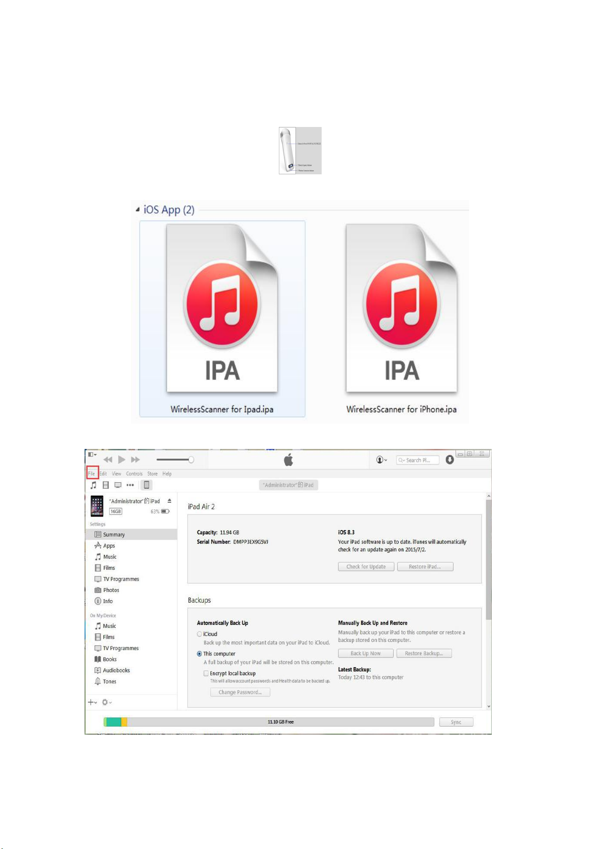
2.2 INSTALLING APP
The software is installed by computer after connecting iPad or iPhone to computer.
Before software installation, please make sure your computer has installed the Apple iTunes.
And please copy the wireless scanner Application to the computer disk. There are two separate
applications, one for IPAD, another for IPHONE.
1) Connect the IPAD or IPHONE to your computer, Open iTunes, Choose File menu, marked with
Red border.
4
Page 11
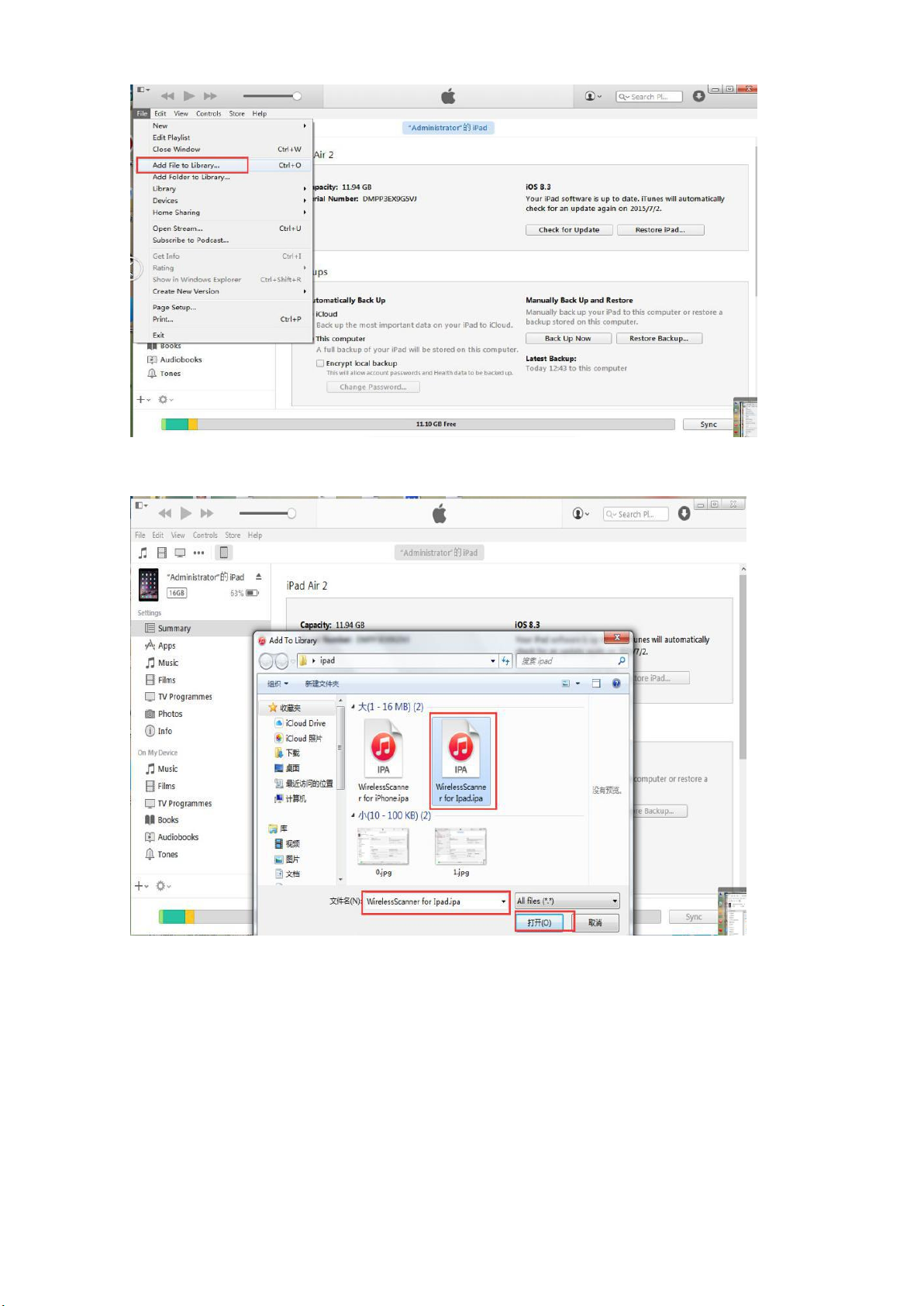
2)Choose menu Add File to Library...
3) Choose Application for IPAD or IPHONE, confirm it.
5
Page 12
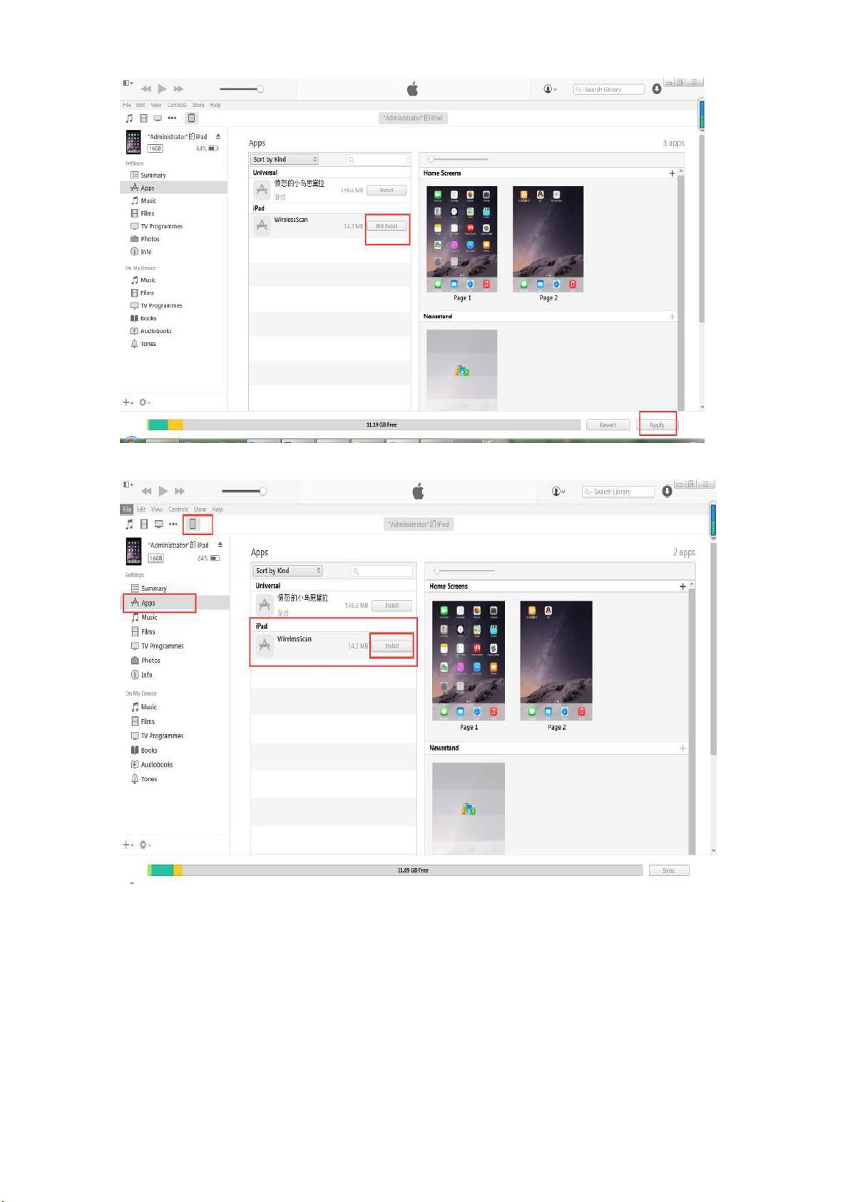
4)Choose IPAD, Enter into Apps menu, the Apps option would appear the added application. Choose
Install the WirelessScan Application.
5) Click Install, the menu changes to Will Install, choose Apply. Startto install the application.
6
Page 13
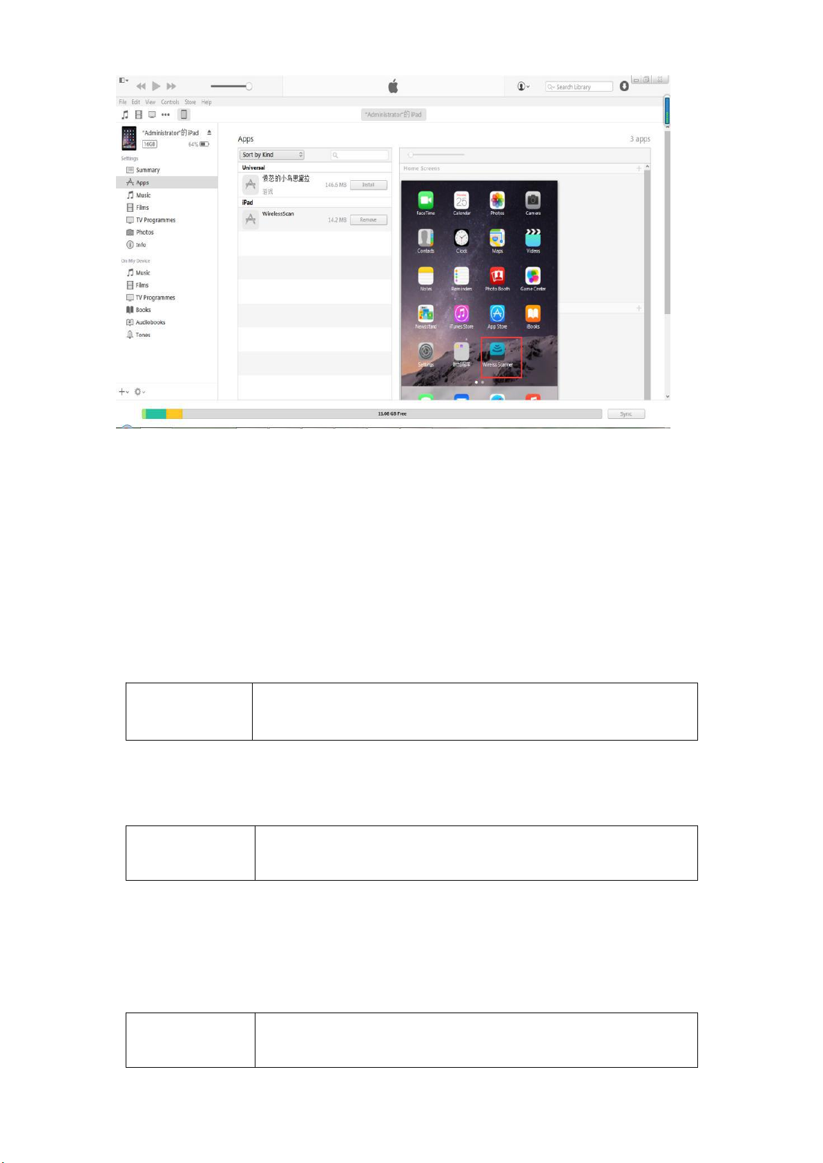
6) The wireless Scanner Application is installed successfully.
Waring
Abnormal probes can cause electric shock or injury to people.
Therefore, once any abnormalities are found, you must
immediately stop using the probe and contact Sonostar.
Caution
Probes that have not been cleaned or disinfected may cause
bacterial and viral infections
Caution
If the operator places an abnormally hot probe on the surface
of the patient's skin, it may cause burns.
Note: if your system is iOS9, need to authorize at Settings - General - Profiles - tap on the Profile - tap
on Trust button.
2.3 STARTING PROBE
2.3.1 Visual inspection
Before and after the ultrasonic visual inspection, check the probe surface or the
fuselage sheath for abnormalities such as peeling, cracks, and bulging.
2.3.2 Probe cleaning
Ultrasonic probes should be cleaned and disinfected before and after ultrasound
examination. Please refer to chapter “4 Cleaning and Disinfection”.
2.3.3 Boot check
Please check the following before diagnosis
1. The probe should not be abnormally heated during use. The probe can be sensed
by hand touching the probe, and if the temperature is significantly higher than
the body temperature (or the probe surface temperature exceeds 40 ° C), the probe
will be stopped.
2. The ultrasound image must not be abnormal after power on, check whether the
functions are normal, including software operation, button function, power, etc.
7
Page 14

Caution
In the event of any of the above anomalies, the ultrasound
imaging diagnostic apparatus may be defective, please contact
SonoStar.
The Wireless Connection Indicator and the Battery Capacity Indicator on the probe may be
invisible before the probe is turned on.
Press the button to turn on the probe. The Battery Capacity Indicator will be light to indicate
the capacity of the battery. The four grids of the indicator imply the battery capacity. (Probe charging
will be described in section 4.)
Seconds after the probe turned on, the Wireless Connection Indicator will be light and blinking
to notice that the probe is ready for a wireless connection from the iPad or iphone.
The probe can be turned off by hold down the button for seconds. When the probe is off, the
indicators will be turned off.
2.4 WIRELESS CONNECTION
When the probe is waiting for a wireless connection as described in previously, launch the
Settings of iPad or iPhone, turn on the Wi-Fi (if not on), Find the SSID of the probe. The SSID is like:
“SS-1 GMBFCA001”, the suffix “GMBFCA001” is a code generated from Serial Number. Connect to
the SSID with the password same as the Serial Number (in lower case). The Serial Number is in the
form like “WSPBFCA001” with the prefix of “WSP”. It can be found on the surface of the probe.
After Wi-Fi is connected, launch the WirelessScan App, after the connection from the app to
the probe is confirmed, the Wireless Connection Indicator on the probe will be light with no
blinking.
Every connection steps are done. The operations of using the system to finish ultrasonography
task will be described in the next section.
8
Page 15
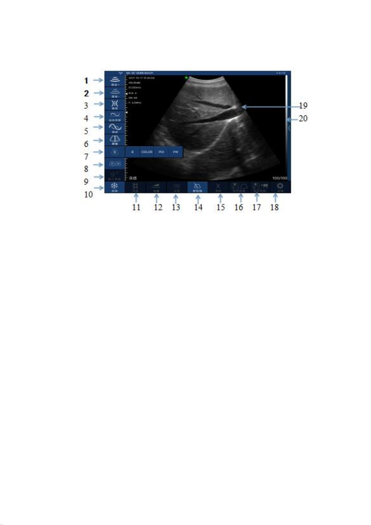
Section 3 APP OPERATIONS
⑴
⑵
⑶
⑷
3.1 ULTRASOUND scanning
Main interface (Figure 3-1)
The meaning of each icon:
1.Gain +: increase image gain.
2.Gain -: reduce image gain.
3. Focus: adjust the focus position of the image.
4.Dynamic range: adjust the dynamic range of the image.
5.Frequency: can change the working frequency of the probe.
6.Noise reduction: used to eliminate low-level echoes caused by noise.
7.Image mode: select image mode.
8.Image mode: B mode, B / M mode, Color Doppler mode (COLOR),
Energy Doppler mode (PDI), Pulse Doppler (PW).
9.Patient information management: patient information input.
10.Freeze/ operate: image freeze and thaw.
11.Movie playback: replay after the image freezes.
12.Measurement: distance / area / obstetrical measurement.
13.Note: enter a comment on the image.
14.Puncture: draw a puncture line for puncture guidance.
15. Delete measurements and notes: delete measurement results and notes on images.
16.Save the image: save a single image.
17. Save Image Video: save whole Image Video.
18.Setting: WIFI channel selection to avoid channel blocking.
19.Depth adjustment: change the depth of the image by sliding up and down the screen of the
phone.
20. TGC (time gain compensation)the function menu pops up by clicking on the top of the right
"<".
9
Page 16
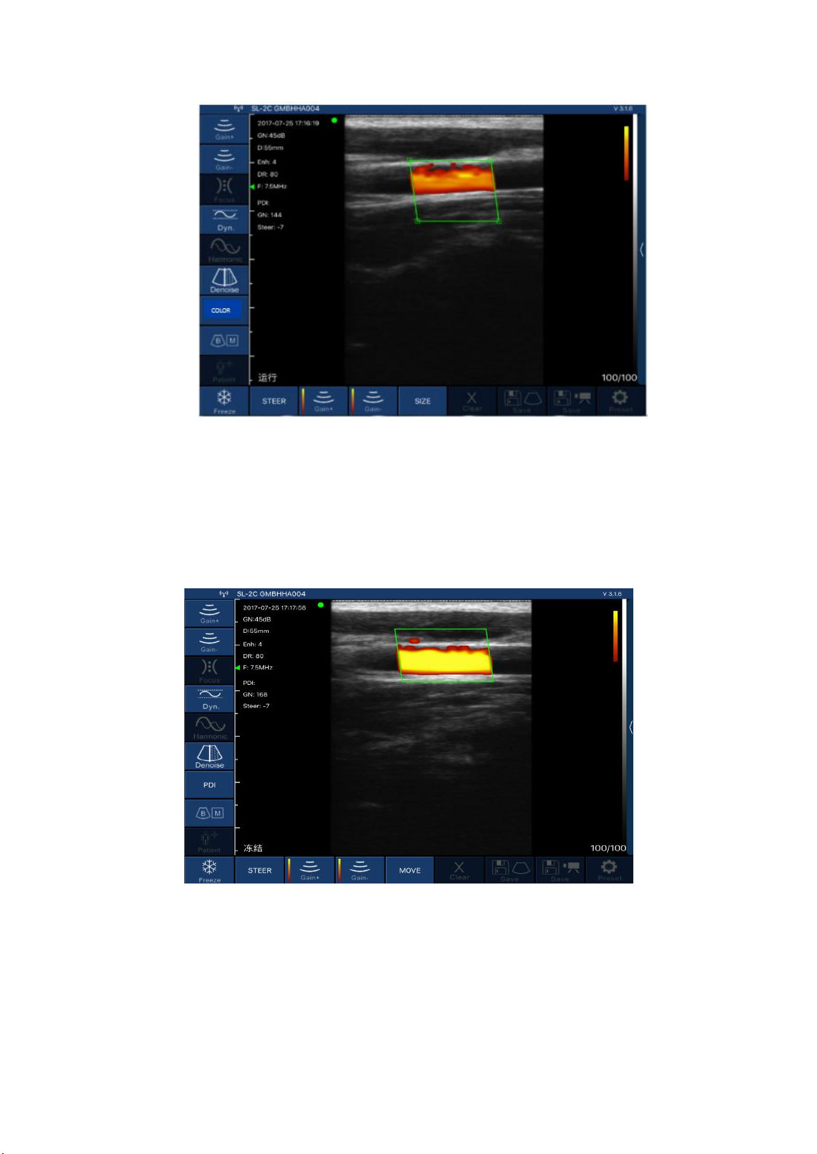
Mode introduction:
Picture 3-2 Color Doppler imaging mode
Color Doppler imaging mode, Picture 3-2:
1.Color sampling frame: change the direction of the color sampling frame.
2.Gain +: increase color blood flow gain.
3.Gain -: reduce color flow gain.
4.Move, Zoom: change the position and size of the color sampling frame by clicking and moving with
your finger.
Picture 3-3 Energy Doppler imaging mode
Energy Doppler imaging mode, Picture 3-3:
1.Color sampling frame: change the direction of the color sampling frame.
2.Gain +: increase energy blood flow gain.
3.Gain -: reduce energy blood flow gain.
4.Move, Zoom: change the position and size of the color sampling frame by clicking and moving with
your finger.
10
Page 17
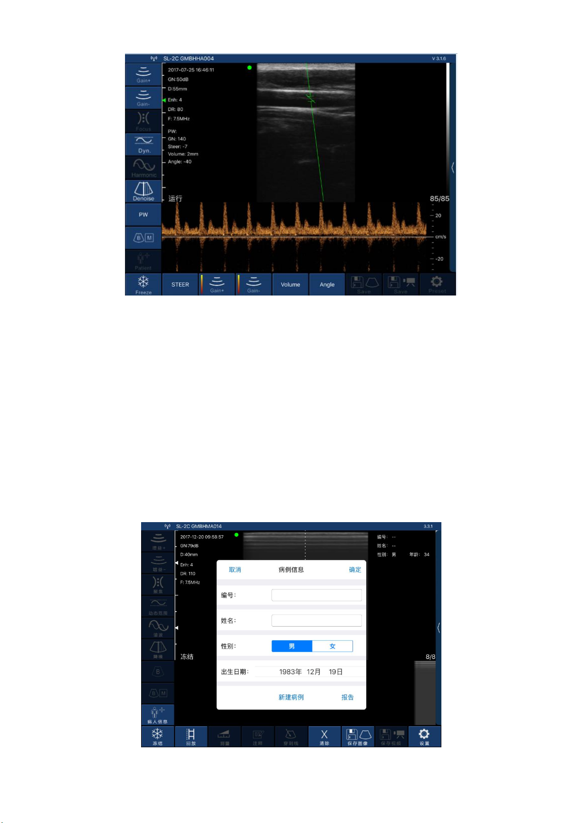
Picture 3-4 Pulse Doppler imaging mode
Pulse Doppler imaging mode, Picture 3-4:
1.Gain +: increase pulse gain.
2.Gain -: reduce pulse gain.
3.Deflection angle: used to change the angle of the spectrum sampling line in real-time scanning
state.
4.Sampling frame: change the size of the sampling volume.
5.Correction angle: used to change the angle of the blood flow direction cursor.
3.3.2 Patient information input
Click on the software interface "Patient Information", thethe interface patient information will pop
up as below Picture 3-5 shows:
Picture 3-5 Pop-up patient information interface
Enter the patient information in the number and name fields, click on the gender and click OK. The
patient information is entered. If you make a mistake, you can click Cancel or create a new case.
11
Page 18
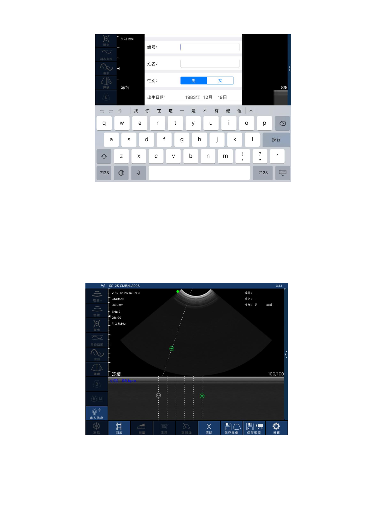
Picture 3-6 Patient Information Editing Interface
3.3.3 Data measurement
In B/M mode, the position of the sampling line can be adjusted by tapping the moving circle on
the screen with your finger (as shown in Picture 3-7 below).
In the frozen state of B/M mode, click the M mode area, the moving circle can appear, the heart
rate can be measured, and the default number of cardiac weeks is 5 weeks (five-segment, that isfive
heartbeat intervals are taken and the average heart rate is calculated).
Picture 3-7 Measuring the heartbeat interface
Click “Measure” in the B mode freeze state, and then the ten measurement functions of the
screen shown in Picture 3-8 will pop up. Users should select the appropriate measurement function
according to the product probe model, the applicable range and the data to be measured.
12
Page 19
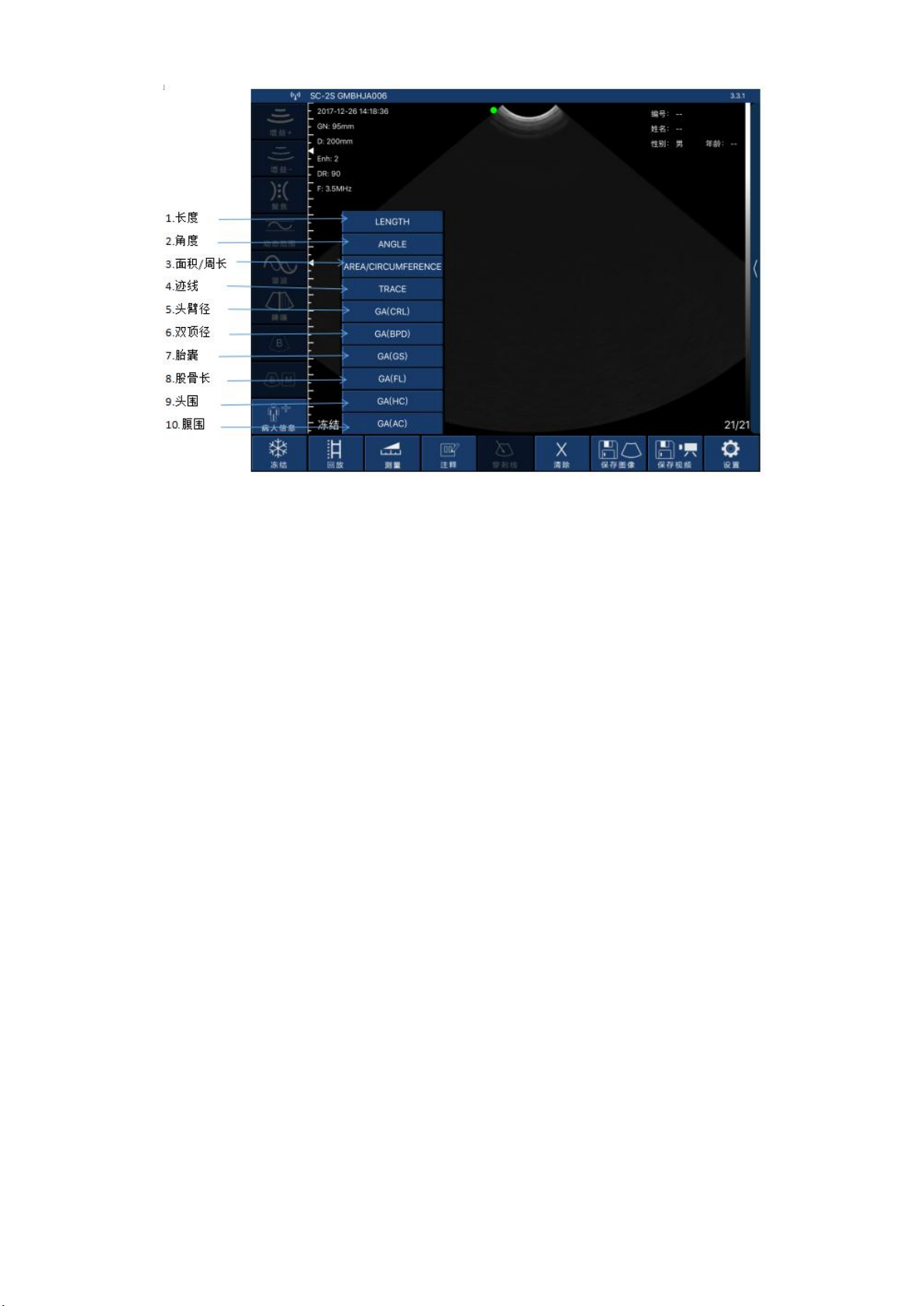
Picture 3-9 Measurement function
After selecting the “LENGTH” length measurement function, click on the two points to be
measured in the frozen screen, the measurement trajectory will appear, click the moving point on
the trajectory line (as shown in the middle of Figure 3-7), move the trajectory, adjust the length. The
size of the real-time measurement data is displayed at the top right of the screen. Among them, GA
(CRL), GA (BPD), GA (GS), and GA (FL) are measured in the same manner.
Select the "AREA/CIRCUMFERENCE" area/circumference measurement function, select the 3
o'clock position to be measured in the frozen screen and click on it. 3 moving points will appear on
the screen, and 3 moving points will automatically form an elliptical trajectory. Click on the moving
point to adjust the measurement position, and the measured data will be displayed in real time on
the upper right of the screen. Among them, GA (HC) and GA (AC) are measured in the same way.
Select the “ANGLE” angle measurement function to measure the angle. You can select the 3
o'clock position to be measured in the frozen screen and click it will appear 3 moving points on the
screen. 3 moving points will automatically form an angle. Click the moving point to adjust the
measuring angle. The measured data is displayed in real time on the upper right.
After selecting the “TRACE” track area measurement function, you can measure the irregular
position area of the edge, and draw the edge on the screen with your finger to get the area size.
The final measured data is displayed at the top right of the screen.
Note: Measurement functions GA (CRL), GA (BPD), GA (GS), GA (FL), GA (HC), and GA (AC) are
only available for obstetrics.
The above measurement functions can be fine-tuned using the virtual trackball of the screen.
During the measurement, you can click on the generated measurement point, and the virtual
trackball that appears (as shown in the lower right corner of Figure 3-10) can be fine-tuned
according to the direction of the measurement point.
13
Page 20
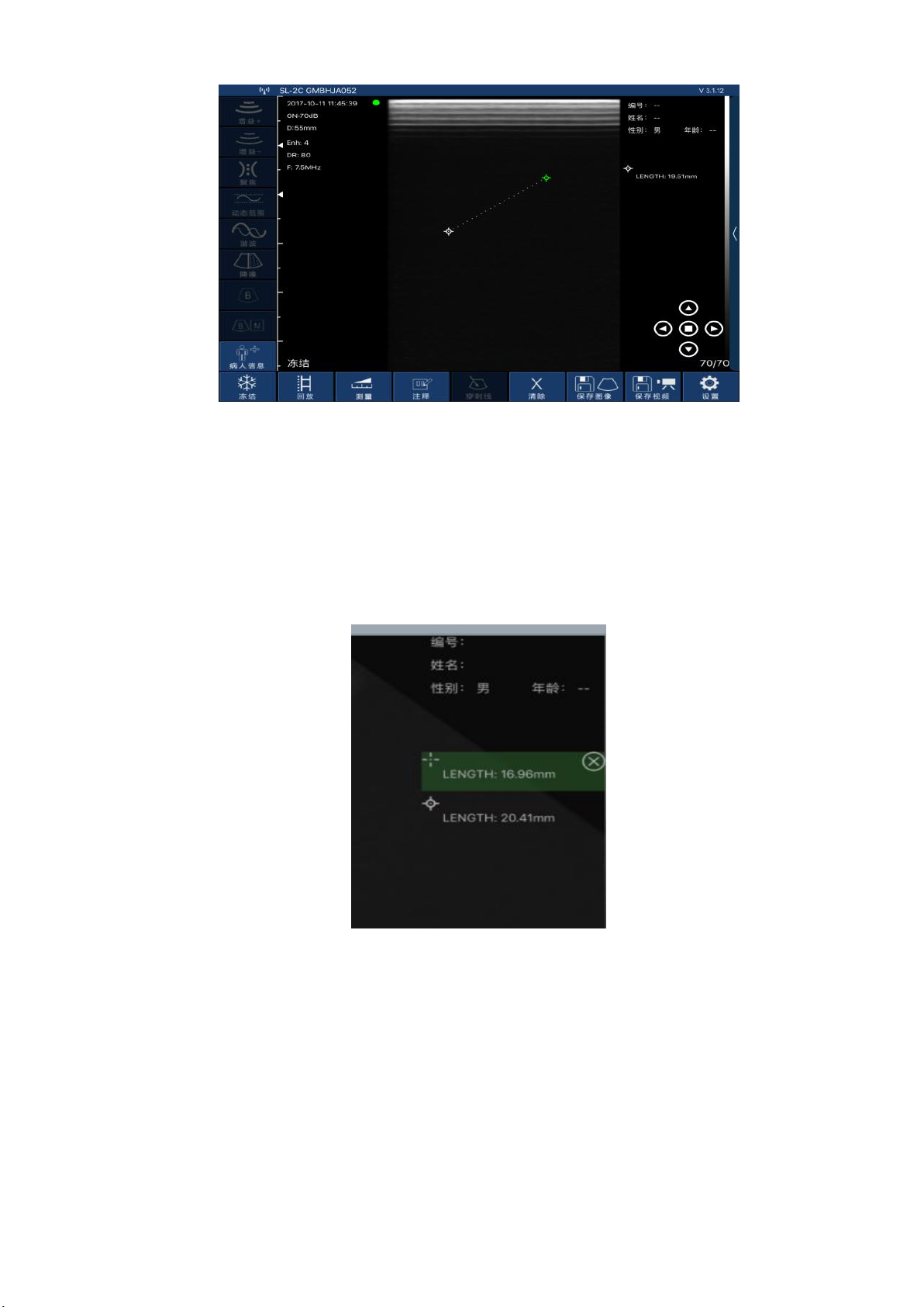
Picture 3-10
Up to 4 sets of data can be measured in the same frozen screen. After the measurement, press
“Clear X” to delete all measurement results. If you want to delete a measurement, click on the
measurement data at the top right of the screen to display the result.
3-11,Within the same freeze frame, the measurement can be at most four sets of data. After finish
the measurement, press the "remove X" can delete all measurements; if you want to delete one
measurement, click measuring data result on the top right screen , immediately appear below as
shown in figure 3 to 11, click "ⓧ" on the right side of the data, delete the measurement data.
Figure3-11 Delete part of the measurement data
3.3.4 Report download
Click on the "patient information" on the lower left of the software interface ,
then pop-up below patient information interface.
14
Page 21
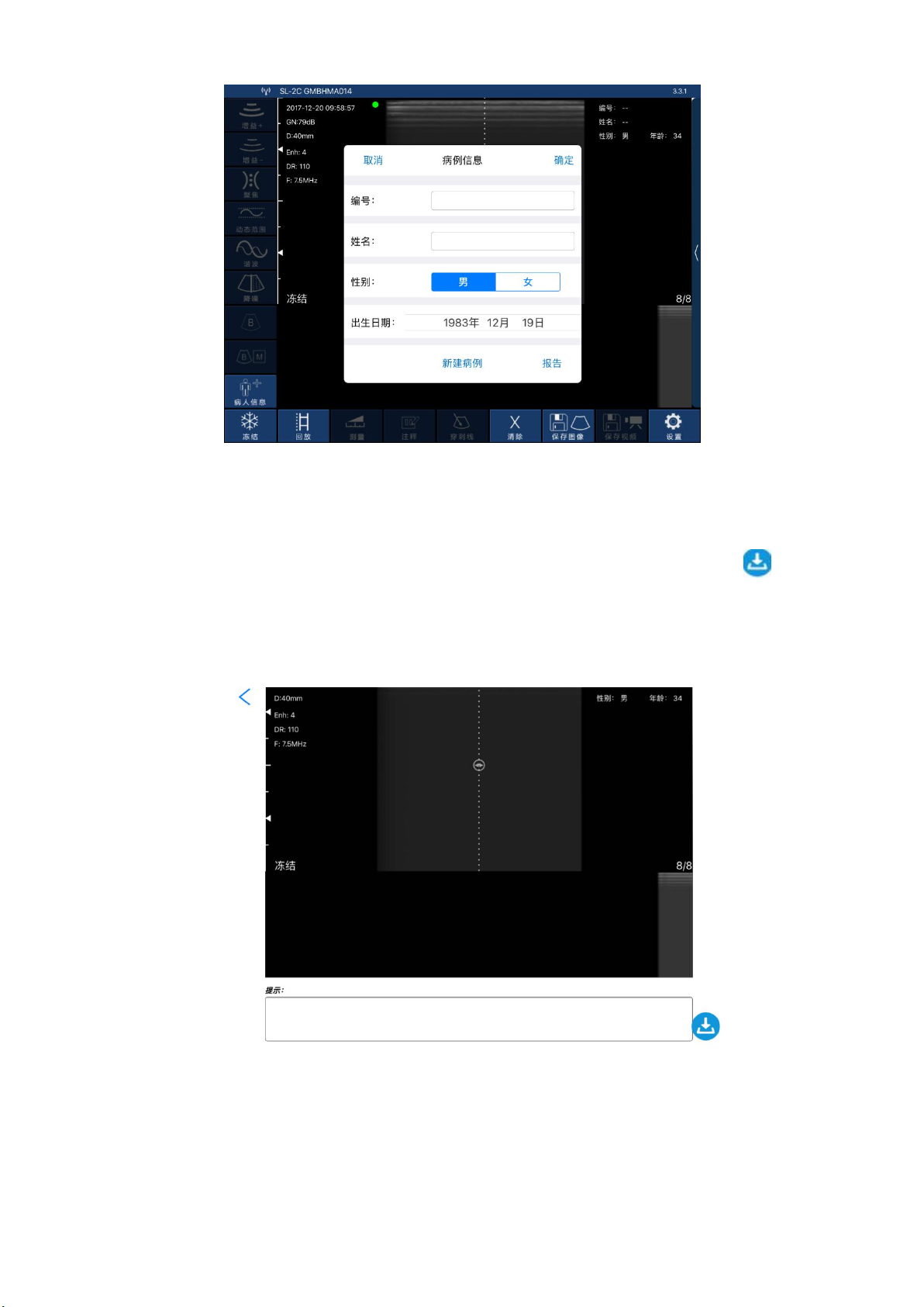
Figure 3-12 pop-up patient information interface.
Click on "report",pop up the interface below as shown in figure 3-13, click on
the "tip" box, the user can input content in dialog box. Click on download icon " "on
the lower right of the page,then the report can be downloaded.The report are stored
automatically in the smart terminal display system (apple mobile phone, or tablet)
photo album.
figure 3-13 patient information download interface
3.3.5image and vedio storage
3.3.5.1 Image storage
Click on "save image" on the bottom right in below interface (FIG. 3-14), then
save the image displaying on the screen at the moment.The image is automatically stored
in the smart terminal display system (apple mobile phone, or tablet) photo album.
15
Page 22
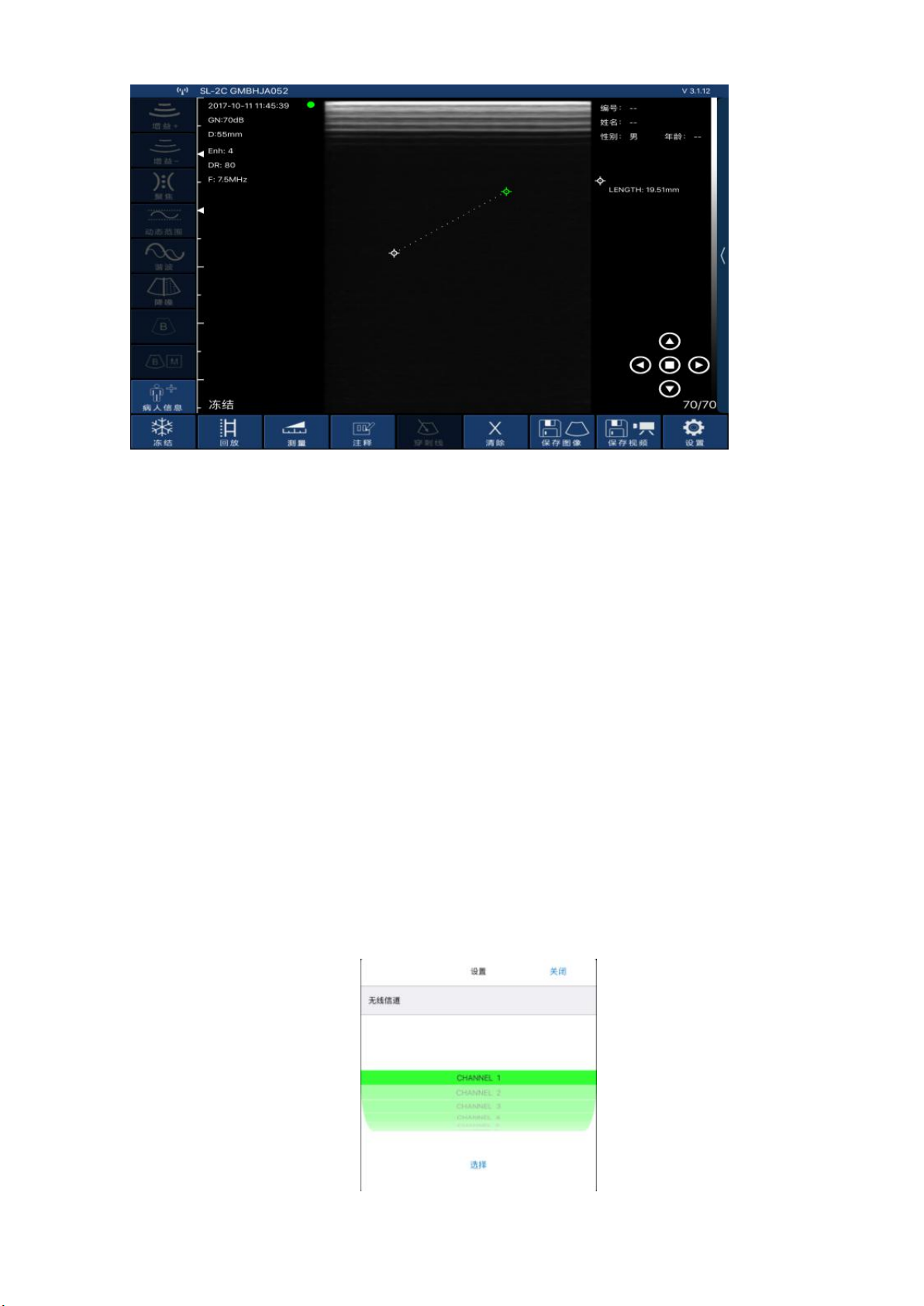
图 3-14
3.3.5.2 Vedio storage
Click on "save vedio" on the bottom right in above interface (FIG. 3-14),then the
vedio starting from the operation within 100seconds are stored in the smart terminal
display system (apple mobile phone, or tablet) photo album.
.
3.3.6 Image and vedio review
Open the photo album of the smart terminal display system (apple mobile phone,
or tablet),then review the saved image and vedio.
3.3.7Replace the signal channel
In the WIFI crowded environment, the user can choose different WIFI channel for
the probe. Press "set" key, then pop up the signal channel selection list ( as showed
in figure 3 to 15), click select channel. After 2 seconds, please restart the probe
and connectwith intelligent terminal display screen according to 3.1 step .
Figure 3-15
16
Page 23
Section 4 MAINTEANCE
Caution
If the adapter power supply voltage is beyond the scope of
instrument regulation adaptation (normal adapter output
voltage is 5 V + / - 0.5 V), it shall not be used.
Check the power cable, if any damage and fracture occur, power
cable should be replaced immediately to meet the requirements.
4.1 PROBE CHARGING
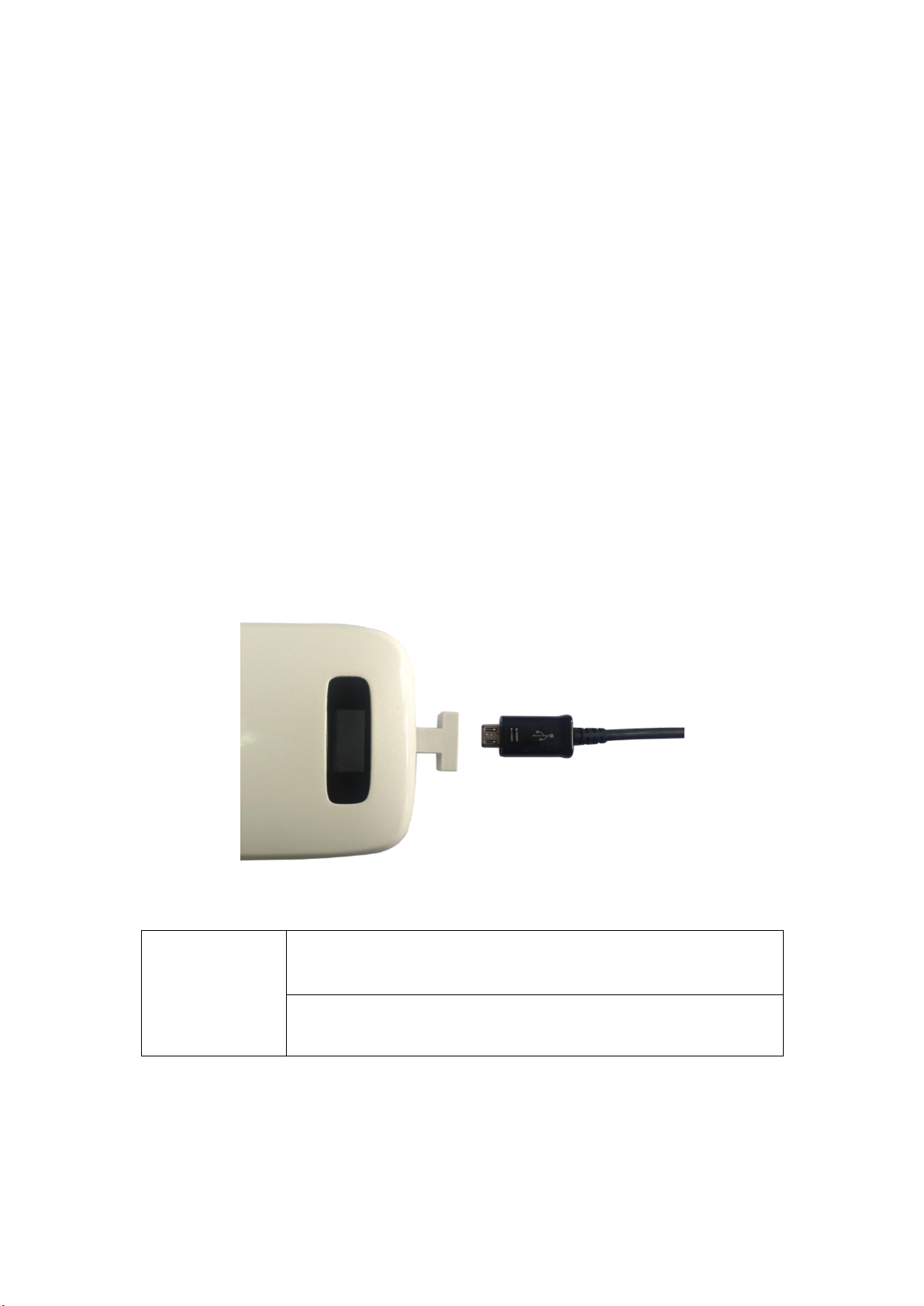
When battery is insufficient,the probe needs charging. Pull out the rubber plug
at the end of the probe,connect probe and the USB charger by USB cable as shown in
figure 4-1.When charging,battery capacity indicator light is flashing.The grid shows
the electricity sufficiency.
If all four grid light and light is not flashing,it indicates the battery is charged
fully. When charging completed, please remove USB cable,then insert rubber plug into
the probe end to avoid liquid and damage the instrument.
Figure 4-1 Charge the Probe
4.2 WATERPROOF IPAD
A waterproof bag is provided by local repository. Users can use it to protect the iPad when it is
used in humidity or dirty fields.
17
Page 24

4.3 CLEANING AND DISINFECTION
Ite
Failure Prolem
Solution
1
No response after press the power
switch
Charging,check the power supply
2
Intelligent display can't connect
probe WIFI
Check the WIFI signal channel is ready;
test whether the WIFI password input is correct
3
Displayed on the screen with
interference like snow
Check if other equipment started which cause
electromagnetic interference,shut down the
device or get far from the device.
4
The image not bright
Adjust brightness
5
Charging not work
Detect circuit and electrical outlet, check if
the USB interface is damaged
The probe needs to be cleaned before using.
To clean the probe, Use a soft cloth dampened with isopropyl alcohol (or an appropriate
hospital cleaning agent) to wipe the Probe until it is thoroughly cleaned.
If you use a detergent solution to clean the instrument, remove all residual detergent. Dry
the instrument with a clean, soft cloth.
Alternatively, dampen a soft cloth in any glutaraldehyde-based hospital disinfectant solution
such as Cidex. Wipe the instrument with the dampened cloth.
To remove all traces of disinfectant solution, wipe the instrument with a clean soft cloth
dampened in sterile water or potable tap water. Wiping the device three separate times to
remove all residual disinfectant is recommended
Thoroughly dry the instrument with a clean, soft cloth before using.
4.4 STORAGE
When not in use, it is recommended that the equipment should be put in the case. While
stored, the equipment should be protected from temperature extremes.
4.5TROUBLE SHOOTING
Inspect: check if the probe and the host is properly connected.
Fault handling:
4.6Disposal
*Warning: products should not be discarded at will.
-Battery recycling meets local requirements.
-Recycling of waste electrical and electronic products should comply with local laws
and regulations.
18
Page 25

4.7Proudct maintenance and protection
1, this product usage and storage conditions shall comply with the environmental
conditions of section 1.5 in this manual.
2, The prouduct power suppy shall be in accordance with section 1.6 of this manual.
3, If Stop using this product for a long period of time, ensure charging at least twice a
week, every time not less than 1 hour.
4, please do not open the probe cover for cleaning, shake or dismantle the
components inside the probe.
5, Clean and wipe the probe cover by alcohol cotton,and should be operated in the
power-off state.
6, this product should not be frequent startup and shutdown. After shutdown if
needed to start up again, please wait at least 1 minute of time for boot operation.
7, if instrument malfunction occur,pls ask professional staff for maintenance.
8, probes are valuble and vulnerable part,any collision or drop is forbidden.
9, Suspended in the diagnosis process, please press the button for freeze.The system in
the frozen statebenefit to probe for long-term use.
10,Apply the medical ultrasound coupling agent which complys with relevant
standards when using the probe.
11, the structure of the probe is watertight, prohibit any conductive liquid
immersionso as to avoid corrosion of the probe and the fuselage.
12,Probe into liquid shall not exceed the probe water lines, and regularly check for
cracks in order to avoid liquid immersion and damage to internal components.
13,After each usage,please refer to chapter 4 of this manual for cleaning and
disinfection.
19
Page 26
Section 5 Safety
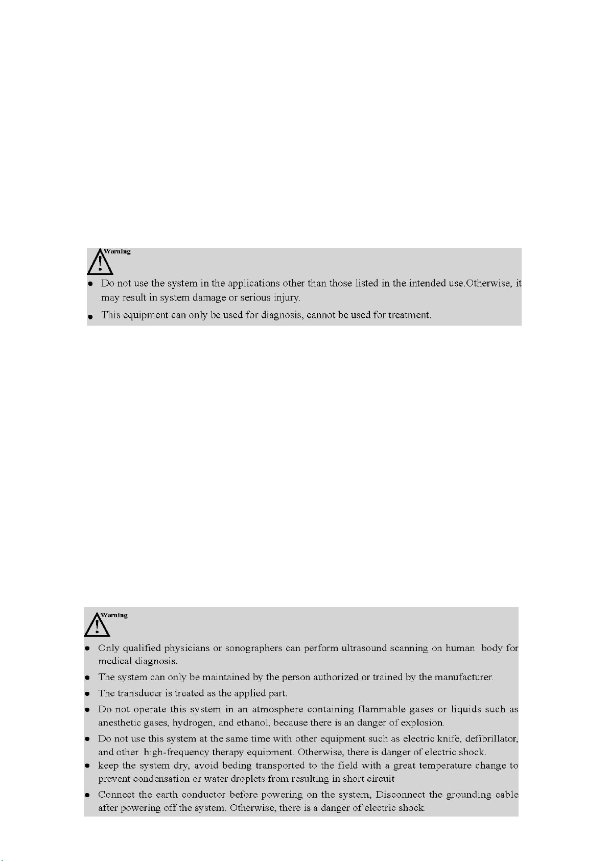
The operation safety is the most important concern of the designer . To ensure the safety and
efficiency of the system, the operator should read carefully about this chapter before using the
system.
5.1 Safety Instructions
Read and understand all precautions in this manual before using the system.
Keep this manual with the system at all times. Periodically review the procedures for operation and
safety precautions.
To maintain the performance and safety of the system, electric and mechanical safety inspections for
the system should be performed periodically by professional technicians in less than 6 months.
5.1.1Electric Safety
● The biocompatibility of this product has been verified, in normal circumstances, it will not
bring harm to the operator or patient.
●
No modification of this equipment is allowed.
● If any operator requests more information such as circuit diagrams, parts list and product
descriptions, for repairs carried out by qualified technical personnel, please contact us.
● Please check and replace the battery periodically.
●
connected to a supply mains with protective earth.
● Do not pour any fluid onto the ultrasound system surfaces, as fluid seepage into the electrical
circuitry may cause excessive leakage current or system failure. If carelessly pour any water onto the
system, immediately stop using the ultrasound system and contact Service Representative
immediately.
●
be performed, and an accident such as a fire may result in the worst case.
● The machine that are not serviced or maintained can not be used on the patient.
● The outer surface of the portions of transducer assembly which is intended to be
inserted into a PATIENT should be checked to ensure that there are no unintended rough
surfaces, sharp edges or
●
Warning: Class I equipment, to avoid the risk of electric shock, the equipment must only be
Only use the probes provided by the manufacturer. Otherwise, the ultrasound system cannot
protrusions which may cause harm.
Please read the instructions and then set and control the acoustic output levels.
5.1.2Mechanical Safety
20
Page 27
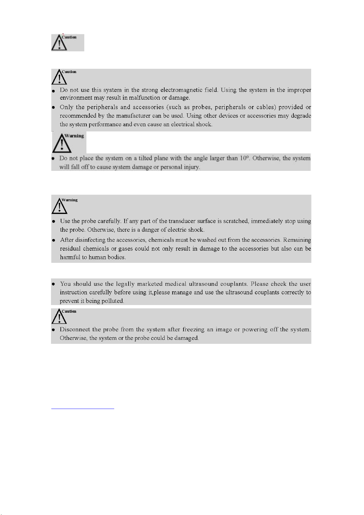
● Be careful when holding the device, for it is handhold, it may fall.
●
Do not use shell cracking equipment.
5.1.3 Accessories Safety
5.1.4 Cybersecurity
●In order to avoid database loss and damage, please back up the database regularly.
●
The probe can be connected to mobile device IPad or IPhone by wireless local network. The
software itself can not be connected to external network, the network the software is connected to
is the local wireless network launched by the probe.
● During usage, if there is any software bug, the user can do feedback via company email:
[email protected], then the company will do analysis and modification according to the bug, if
there is needs for update, there will be update notification via email to remind the user to do
update.
21
Page 28
5.2 Principles of Using Acoustic Power
5.2.1 Biological Safety
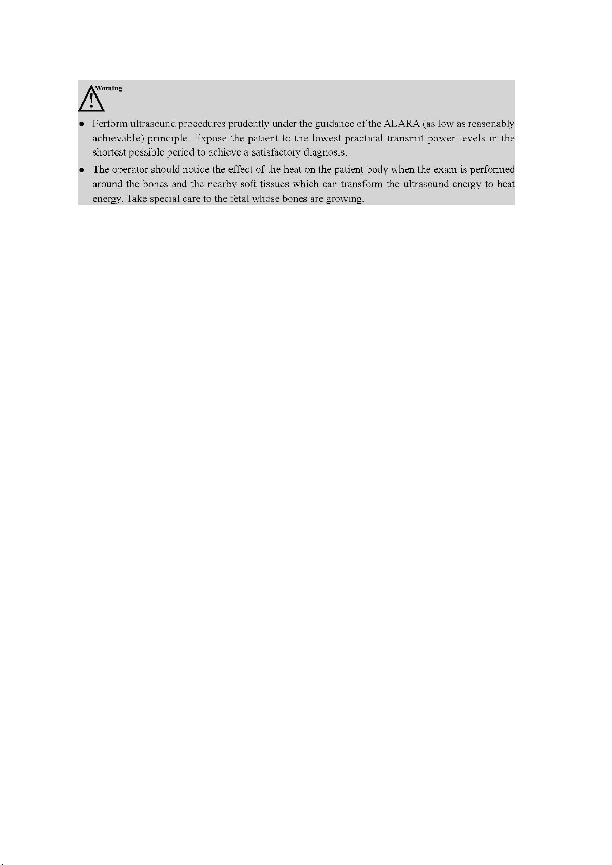
Diagnostic ultrasound is recognized as being safe, but the risk of biological effects exists when using
it in high exposure levels and long exposure times. Thus ultrasound should be used in a prudent
manner to provide medical benefit to the patient.
5.2.2 Mechanical and Thermal Indices
The ultrasound system displays two parts: thermal Index (TI) and Mechanical Index (MI). The MI/ TI
value of the machine is real time displayed at the upper right corner, regarding how to change TI
display type, please choose: Preset → [System Preset] → [TI].
■ Meaning of MI/TI
Mechanical bioeffects are threshold phenomena that occur when a certain level of output is
exceeded. The threshold level varies with tissue type. The potential mechanical bioeffects varies
with peak pressure and ultrasound frequency. The higher the MI value, the greater the likelihood
of mechanical bioeffects occurring. There is no specific MI value theat means that a mechanical
effect is actually occurring. The MI should be used as guide for implementing the ALARA
principle.
The TI value informs the operator about the conditions that might lead to an increase in
temperature at surface of the body, within the body tissue, or at the point of focus of the
ultrasound beam on bone. That is, the TI value informs the operator about the potential
temperature rise in body tissue. It is an estimate of temperature increase in body tissue with
specific properties. The actual amount of an temperature rise is influenced by factor such as
tissue type, vascularity, mode of operation and others. The TI value should be used as a guide
for implementing the ALARA principle. Depending on the examination and type of tissue
involved, TI could be one of three types.
Soft Tissue Thermal Index (TIS) is used when imaging soft tissue only, it provides an estimate
of potential temperature rise in soft tissue.
● Bone Thermal Index (TIB) is used when bone is near the focus of the image as in the third
cropester OB examination, it provides an estimate of potential temperature rise in the bone or
adjacent soft tissue.
● Cranial Bone Thermal Index (TIC) is used when bone is near the skin surface as in transcranial
examination, it provides an estimate of potential temperature rise in the bone or
■ Precision of MI/TI
adjacent soft tissue.
TI and MI values are displayed in real time on the screen. The operator should observe these
index values during examinations and ensure that exposure time and output values are
maintained at minimum amounts needed for effective diagnosis. The MI and TI precision is 0.1.
5.2.3 Acoustic Output Statement
5.2.3.1 The Influencing Factors of Acoustic Uncertainty
When estimating accuracy of displayed numerical values,many factors are considered:
●The probe changeability
22
Page 29

●The system changeability
1. The sensitivity of hydrophone:According to hydrophone calibration report provided by ONDA
2. Scope: according to agilent DSO6502A specifications, its effect on the sound pressure is plus or
3. Temperature: effect of the thermocouple on sound pressure error is plus or minus 4%;
●Changeability and accuracy of measurement
●Possible operating conditions and testing numbers needed to obtain displayed result accuracy of the
diagnostic system
●Whether the display accuracy depends on specific system combination, mode combination , probe
component and launch mode combination, or all of above
●Algorithm accuracy of the system software used to calculate the MI/TI
●Approximation engineering method used in real time computation
5.2.3.2 Differences between Actual and Displayed MI and TI
For many assumptions used in the process of measurement and calculation, actually they are
conservative. For most organizations path, high estimate is made in the measurement and calculation
process of tissue exposure intensity. For example, using attenuation coefficient 0.3dB cm-1MHz
much lower than the actual human tissue attenuation coefficient, choosing conservative values of
tissue characteristic. Therefore, displayed MI and TI values should be relative information for
reference, they serve to indicate to the operator whether a particular setting of the system increases or
decreases the possibility of Thermal or Mechanical effect, used to help the operator be careful to use
ultrasonic diagnostic system and follow the ALARA principle, these values can not be equal to actual
values.
5.2.3.3 Uncertainty of Measurement
Sound pressure is the most basic data of sound field measurement, and other sound field parameters
can be deduced from sound pressure, so when analysing measurement uncertainty, only take sound
pressure for analysis and uncertainty of other parameters can be deduced from the sound pressure.
-1
Measurement uncertainty mainly include repeated measurement uncertainty and the system
uncertainty, the system uncertainty is an order of magnitude higher than repeated measurement
uncertainty, so the main analysis is the system uncertainty. Mainly decided by the following
factors:
company, the maximum allowable error of sound pressure for hydrophone is plus or minus 12%;
minus 2%;
Above all uncertainty components are not related, synthetic standard uncertainty of sound pressure
is :plus or minus 13%.
5.2.4 Operator Control Property
There are three types of operation control related to the generation of mechanical/thermal effect:
direct control and indirect control, receiver control. Qualified operator should try to cut down the
acoustic output in the premise of effective diagnostic images.
■ Direct control The direct control of the acoustic output of this system is adjusting voltage size. But
its maximum acoustic output shouldn't be more than displayed acoustic output limit in any modes.
■ Indirect control
The controls that indirectly affect output are many imaging parameters. These are operating modes,
frequency, focal point number/position, image depth and pulse repetition frequency (PRF)(By
adjusting the [Scale] of the toolbar).
The operating mode determines whether the ultrasound beam is scanning or non-scanning. Thermal
effect is closely connected to M Mode, PW Doppler and Color Mode.
Acoustic attenuation of tissue is directly related to transducer frequency.
The focal point number and position is related to active aperture of transducer and beam width.
For the pulse repetition frequency( PRF)(By adjusting the [Scale] of the toolbar), the higher the PRF,
23
Page 30

the more acoustic output power increased over a period of time.
■ The receiver control
The receiver control does not affect the acoustic output, including gain, dynamic range, and image
processing, etc. Therefore, in the image optimization, should adjust the receiver control to optimize
images firstly, the second are through direct control and indirect control.
When acquiring images, it is recommended to use the default (or as low as possible) acoustic output
location, and use the gain control to compensate. The default setting is commonly 70% of maximum
allowed acoustic output value, which will not cause harm to the operator, and for the probe is the
most effective value
5.2.5 Acoustic Power Settings
The ultrasound system has been preset the parameters for each exam mode with different probes
before shipment. When the ultrasound system is powered on, a new patient is created or the
application mode is changed, the system will retrieve the default settings. You can also reset the
parameters.
5.2.6 ALARA
It is required to practice ALARA when using ultrasound energy. Practicing ALARA ensures that the
total energy level is controlled below a low level at which bioeffects are not generated while
diagnostic information is being accumulated. The total energy is controlled by output intensity and
total radiation time. The output intensity necessary for examinations differs depending on the patient
and clinical case.
Not all examinations can be performed with an extremely low level of acoustic energy. Controlling
the acoustic level at an extremely low level leads to low-quality images or insufficient Doppler
signals, adversely affecting the reliability of the diagnosis. However, the sound power which is used
greater than the actual needs does not contribute to improving the quality of diagnostic information
either, it will increase the risk of biological effects.
The operator must take responsibility for the safety of patients.
5.3 Electromagnetic Compatibilities
Electromagnetic compatibilities are the abilities of the system or equipment to operate normally in
the electromagnetic environment and not to radiate any electromagnetic interruptions to any other
objects which are in the same environment.
This system is designed in accordance with the current EMC requirement. And the ultrasound image
will degrade instantly if the system is used in the electromagnetic field environment. If the
degradation of the image is found, it is recommended to inspect the operation environment to confirm
the radiation source.
24
Page 31

5.3.1 Electromagnetic Emission
1
Guidance and manufacturer’s declaration - electromagnetic emission
2
The CProbe Wireless Probe Type Ultrasound Scanner is intended for use in the
electromagnetic environment specified below. The customer or the user of CProbe Wireless
Probe Type Ultrasound Scanner should assure that it is used in such environment.
3
Emission test
Compliance
Electromagnetic environment - guidance
4
RF emissions
CISPR 11
Group 1
The CProbe Wireless Probe Type Ultrasound Scanner
uses RF energy only for its internal function.
Therefore, its RF emissions are very low and are not
likely to cause any interference in nearby electronic
equipment.
5
RF emissions
CISPR 11
Class B
The CProbe Wireless Probe Type Ultrasound Scanner
is suitable for use in all establishments, including
domestic establishments and those directly connected
to the public low-voltage power supply network that
supplies buildings used for domestic purposes.
6
Harmonic emissions
IEC 61000-3-2
Class A
7
Voltage fluctuations /
flicker emissions
IEC 61000-3-3
Complies
This system is applicable for the following environment. You should use this system under the
suggested environment.
25
Page 32

5.3.2 Electromagnetic Immunity
Guidance and manufacturer’s declaration - electromagnetic immunity
The CProbe Wireless Probe Type Ultrasound Scanner is intended for use in the electromagnetic
environment specified below. The customer or the user of the CProbe Wireless Probe Type
Ultrasound Scanner should assure that it is used in such an environment.
Immunity
Test
IEC 60601
Test Level
Compliance
Level
Electromagnetic environment - guidance
Electrostatic
discharge
(ESD)
IEC61000-4
-2
±6kV contact
±8kV air
±6kV contact
±8kV air
Floors should be wood,concrete or ceramic tile.
If floors are covered with synthetic material, the
relative humidity should be at least 30%.
Electrostatic
transient \
burst
IEC
61000-4-4
±2 kV for
power supply
lines
±1 kV for
input output
lines
±2 kV for
power supply
lines
±1 kV for
input output
lines
Mains power qualityshould be that of a
typical commercial or hospital environment.
Surge
IEC
61000-4-5
±1kV
differential
mode
±2kV
common
mode
±1kV
differential
mode
±2kV common
mode
Mains power quality should be that of a typical
commercial or hospital environment.
Voltage
dips, short
interruptions
and voltage
variations
on power
supply input
lines
IEC
61000-4-11
< 5%U
T
(>95% dip in
UT) for 0.5
cycle
40%UT(60%
dip in UT) for
5 cycles
70%UT(30%
dip in UT) for
25 cycles
< 5%U
T
(>95% dip in
UT) for 5 sec
< 5%U
T
(>95% dip in
UT) for 0.5
cycle
40%UT(60%
dip in UT) for
5 cycles
70%UT(30%
dip in UT) for
25 cycles
< 5%U
T
(>95% dip in
UT) for 5 sec
Mains power qualityshould be that of atypical
commercial or hospital environment. If the user
of the CProbe Wireless Probe Type Ultrasound
Scanner requires continued operation during
power mains interruptions, it is recommended
that the CProbe Wireless Probe Type
Ultrasound Scanner be powered from an
uninterruptible power supply or a battery.
Power
frequency
(50/60 Hz)
Magnetic
field
IEC
61000-4-8
3 A/m
3 A/m
Power frequency magnetic fields should be at
levels characteristic of a typical location in a
typical commercial or hospital environment.
NOTEUT is the a.c. mains voltage prior to application of the test level.
26
Page 33
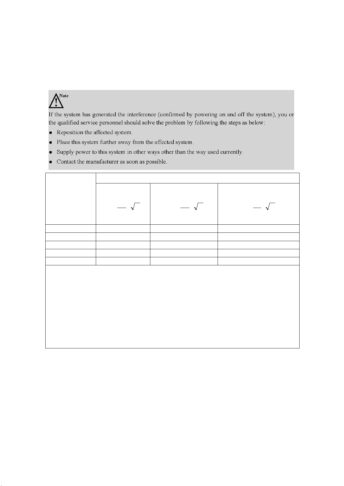
5.3.3 Recommended Separation Distance
Rated Maximum
Output Power of
Transmitter (W)
Separation distance according to frequency of transmitter (m)
150 kHz to 80
MHz
d = [
1
5.3
V
]
P
80 MHz to 800 MHz
d = [
1
5.3
E
]
P
800 MHz to 2.5 GHz
d = [
17E
]
P
0.01
0.12
0.12
0.23
0.1
0.38
0.38
0.73
1
1.2
1.2
2.3
10
3.8
3.8
7.3
1001212
23
For transmitters rated at a maximum output power not listed above, the recommended separation
distance d in meters (m) can be estimated using the equation applicable to the frequency of the
transmitter, where P is the maximum output power rating of the transmitter in watts (W) according to
the transmitter manufacturer.
NOTE 1: At 80 MHz and 800 MHz, the separation distance for the higher frequency range applies.
NOTE 2: These guidelines may not apply in all situations. Electromagnetic propagation is affected by
absorption and reflection from structures, objects and people.
The CProbe Wireless Probe Type Ultrasound Scanner is intended for use in an electromagnetic
environment in which radiated RF disturbance are controlled. The customer or the user of the CProbe
Wireless Probe Type Ultrasound Scanner can help prevent electromagnetic interference by
maintaining a minimum distance between portable and mobile RF communications equipment
(transmitters) and the the CProbe Wireless Probe Type Ultrasound Scanner as recommended below,
according to the maximum output power of the communications equipment.
27
Page 34

Appendix A Specifications
Complied
Standards
EN 60601-1 (IEC 60601-1), Medical electrical equipment Part 1: General
requirements for basic safety and essential performance, Class I, BF, continuous
operation EN 60601-2-37:2008 (IEC 60601-2-37:2007), Medical Electrical
Equipment Part 2-37: Particular Requirements for the Basic Safety and Essential
Performance of Ultrasonic Medical Diagnostic and Monitoring Equipment EN
60601-1-2:2007 (IEC 60601-1-2: 2007), Class A
Safety
Types
Type of protection
against electric
shock
Internally powered
Degree of protection
against electric
shock
Type-BF applied part
Operation mode
Continuous working
Installation and
operation type
Portable Equipment
Degrees of
protection against
harmful liquid
IPX5
Degree of safety of
application
The equipment is not suitable for use in the presence of a
flammable anesthetic mixture with air, oxygen or nitrous
oxide.
Environm
ental
Requirem
ent
Operations
Storage and Transportation
Relative Humidity
25% to 80%,
non-condens
ing
25% to 93%, non-condensing
Ambient
Temperature
5°C to
+40°C
-20°C to +55°C
Atmospheric
Pressure
700hPa to
1060hPa
700hPa to 1060hPa
Max. Altitude
3000m
3000m
28
Page 35
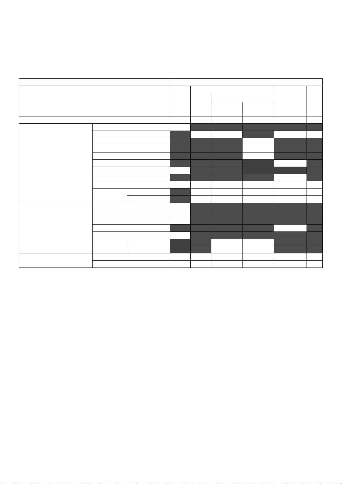
Appendix B Acoustic Output Data
Transducer Model: CProbe, SN:WSPBGCA042
Operating Mode:Bmode
Index label
MI
TIS
TIB
TIC
Scan
Non-scan
Non-scan
A
aprt
≤1
cm
2
A
aprt
>1
cm
2
Maximum index value
0.65
0.16
N/A
Associated acoustic
parameters
p
r.α
1.17
P
13.31
N/A
min of [Pα(Zs),I
ta.α(Zs
)]
z
s
z
bp
z
b
z at max I
pi.α
4.70
deq(Zb)
f
awf
3.25
3.25
N/A
Dim of A
aprt
X
1.29
N/A
Y
1.30
N/A
Other information
td0.73
prr
1250
prat max I
pi
2.10
deqat max I
pi
I
pi.α
at max MI
42.30
Focal
Length
FL
x
FL
y
Operating control
conditions
Depth(mm)
160
160
N/A
Freq(MHz)
3.5
3.5
N/A
These data are acquired through the test report of IEC 60601-2-37.
29
Page 36
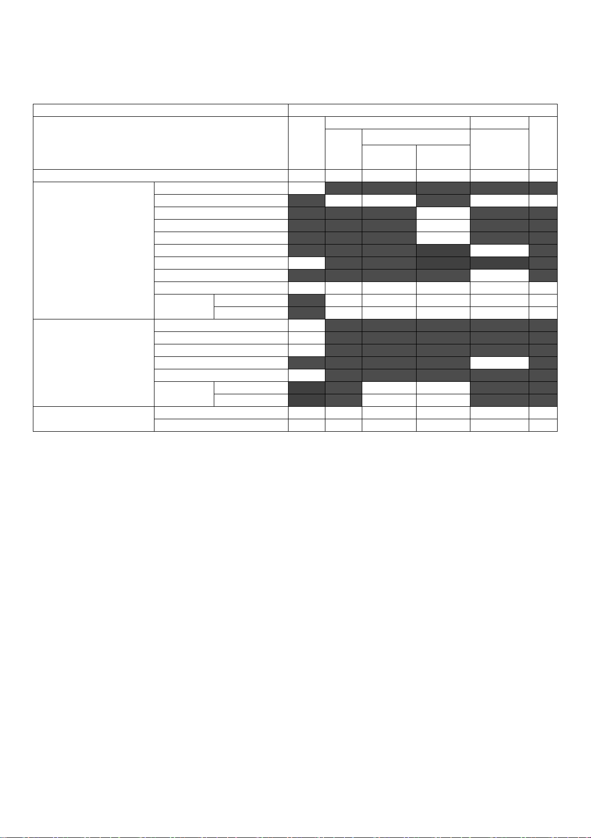
Transducer Model: CProbe, SN:WSPBGCA042
Operating Mode:B+M mode
Index label
MI
TIS
TIB
TIC
Scan
Non-scan
Non-scan
A
aprt
≤1
cm
2
A
aprt
>1
cm
2
Maximum index value
0.65
0.16
0.12
0.37
N/A
Associated acoustic
parameters
p
r.α
1.17
P
13.31
13.11
N/A
min of [Pα(Zs),I
ta.α(Zs
)]
7.68
zs2.40
zbp2.19
zb4.70
z at max I
pi.α
4.70
deq(Zb)
0.62
f
awf
3.25
3.25
3.25
3.25
N/A
Dim of
A
aprt
X
1.29
1.29
1.29
N/A
Y
1.30
1.30
1.30
N/A
Other information
td0.73
prr
1250
prat max I
pi
2.10
deqat max I
pi
0.62
I
pi.α
at max MI
42.30
Focal
Length
FLxN/A
FLy5.00
Operating control
conditions
Depth(mm)
160
160
160
160
N/A
Freq(MHz)
3.5
3.5
3.5
3.5
N/A
After-sale service
Guangzhou Sonostar Technologies Co., Ltd.
customer service contact information service in Guangzhou City.
Address:504#, C Building, #27 Yayingshi Road, Science Town, Guangzhou, Guangdong, 510665, P.R.China
zip code:510665
Telephone:020-82108565
Fax:020-62614030
Email: [email protected]
30
 Loading...