


S6
Portable Digital Color Doppler Ultrasound System
Service Manual
May 5, 2010

S6 Portable Digital Color Doppler Ultrasound System
Service Manual
P/N: 4720-0034-01A 0-2

S6 Portable Digital Color Doppler Ultrasound System
Service Manual
Contents
1 Introduction |
1-1 |
|
1.1 |
Intended Users . . . . . . . . . . . . . . . . . . . . . . . . . . . |
1-1 |
1.2 |
Contact Information . . . . . . . . . . . . . . . . . . . . . . . . |
1-1 |
1.3 |
Software Updates . . . . . . . . . . . . . . . . . . . . . . . . . . |
1-2 |
2 Safety Considerations |
2-1 |
|
2.1 |
Introduction . . . . . . . . . . . . . . . . . . . . . . . . . . . . . |
2-1 |
2.2 |
Symbol Used . . . . . . . . . . . . . . . . . . . . . . . . . . . . |
2-2 |
2.3 |
Electrical Safety . . . . . . . . . . . . . . . . . . . . . . . . . . . |
2-2 |
2.4 |
Mechanical Safety . . . . . . . . . . . . . . . . . . . . . . . . . |
2-3 |
2.5 |
Human Safety . . . . . . . . . . . . . . . . . . . . . . . . . . . . |
2-4 |
3 Description of the System |
3-1 |
||
3.1 |
Product Description . . . . . . . . . . . . . . . . . . . . . . . . |
3-1 |
|
3.2 |
System Configuration . . . . . . . . . . . . . . . . . . . . . . . |
3-2 |
|
3.3 |
Applications . . . . . . . . . . . . . . . . . . . . . . . . . . . . . |
3-4 |
|
3.4 |
Operating Modes . . . . . . . . . . . . . . . . . . . . . . . . . . |
3-5 |
|
3.5 |
Combined Modes . . . . . . . . . . . . . . . . . . . . . . . . . . |
3-5 |
|
3.6 |
Scanning Modes . . . . . . . . . . . . . . . . . . . . . . . . . . |
3-6 |
|
3.7 |
Adjustable Parameters . . . . . . . . . . . . . . . . . . . . . . . |
3-6 |
|
|
3.7.1 |
B Mode . . . . . . . . . . . . . . . . . . . . . . . . . . . |
3-6 |
|
3.7.2 |
Spectral Doppler (PW/CW) . . . . . . . . . . . . . . . |
3-7 |
|
3.7.3 Color Doppler and Power Doppler . . . . . . . . . . . |
3-7 |
|
|
3.7.4 |
Archive and Backup . . . . . . . . . . . . . . . . . . . . |
3-8 |
3.8 |
Measurements and Calculations . . . . . . . . . . . . . . . . . |
3-8 |
|
4 Principle of the S6 System |
4-1 |
|
4.1 |
Introduction . . . . . . . . . . . . . . . . . . . . . . . . . . . . . |
4-1 |
4.2 |
System Block Diagram . . . . . . . . . . . . . . . . . . . . . . |
4-1 |
4.3 |
Principle of Probes . . . . . . . . . . . . . . . . . . . . . . . . . |
4-2 |
4.4 |
Operating Modes . . . . . . . . . . . . . . . . . . . . . . . . . . |
4-2 |
4.5 |
Functional Boards/Units of the S6 System . . . . . . . . . . . |
4-3 |
|
4.5.1 Functional Block Diagram . . . . . . . . . . . . . . . . |
4-4 |
|
4.5.2 Explanations of the System Functions . . . . . . . . . |
4-4 |
4.6 |
Part List . . . . . . . . . . . . . . . . . . . . . . . . . . . . . . . |
4-5 |
5 S6 Disassembly Instructions |
5-1 |
|
P/N: 4720-0034-01A i

|
|
S6 Portable Digital Color Doppler Ultrasound System |
||
|
|
|
Service Manual |
|
|
|
|
|
|
5.1 |
Bottom Cover . . . . . . . . . . . . . . . . . . . . . . . |
. . . . . 5-3 |
|
|
5.2 |
Back Cover . . . . . . . . . . . . . . . . . . . . . . . . . |
. . . . 5-4 |
|
|
5.3 |
Motherboard . . . . . . . . . . . . . . . . . . . . . . . . |
. . . . 5-6 |
|
|
5.4 |
KEAA board . . . . . . . . . . . . . . . . . . . . . . . . . |
. . . . 5-7 |
|
|
5.5 |
HDD |
. . . . . . . . . . . . . . . . . . . . . . . . . . . . . |
. . . . 5-9 |
|
5.6 |
Voltage Conversion Board . . . . . . . . . . . . . . . . . |
. . . . 5-10 |
||
5.7 |
Fans . . |
. . . . . . . . . . . . . . . . . . . . . . . . . . . . |
. . . . 5-11 |
|
5.8 |
MPC board . . . . . . . . . . . . . . . . . . . . . . . . . . |
. . . . 5-12 |
||
5.9 |
Ultrasound Module Assembly . . . . . . . . . . . . . . . |
. . . . 5-12 |
||
|
5.9.1 |
Ultrasound Metal Shield . . . . . . . . . . . . . |
. . . . 5-13 |
|
|
5.9.2 |
Ultrasound Module . . . . . . . . . . . . . . . . |
. . . . 5-14 |
|
5.10 |
Power Unit . . . . . . . . . . . . . . . . . . . . . . . . . . |
. . . . 5-16 |
||
5.11 |
Keyboard Assembly . . . . . . . . . . . . . . . . . . . . . |
. . . . 5-17 |
||
5.12 |
LCD assembly . . . . . . . . . . . . . . . . . . . . . . . . |
. . . . 5-18 |
||
6 Wiring Instructions |
6-1 |
|
||
6.1 |
Introduction . . . . . . . . . . . . . . . . . . . . . . . . . |
. . . . 6-1 |
|
|
6.2 |
Wiring in the System Level . . . . . . . . . . . . . . . . |
. . . . 6-2 |
|
|
6.3 |
Detailed Connection Instructions . . . . . . . . . . . . |
. . . . 6-4 |
|
|
6.3.1Control Cable for Keyboard Unit (3520-0501) . . . . 6-4
6.3.2Connection wires for keyboard small board (3520-
|
|
0502) . . . . . . . . . . . . . . . . . . . . . . . . . . . . |
6-4 |
|
6.3.3 |
Connection wires for trackball (3520-0503) . . . . . |
6-4 |
|
6.3.4 |
Connection cable for loud speakers (3520-0504) . . . |
6-5 |
|
6.3.5 |
Signal Transmission cable for keyboard (3520-0505) |
6-5 |
|
6.3.6 |
SATA cable for HDD (3520-0506) . . . . . . . . . . . . |
6-6 |
|
6.3.7 |
LVDS Signal Cable (3520-0507) . . . . . . . . . . . . . |
6-6 |
|
6.3.8 |
Cables Connecting Keyboard and motherboard (3520- |
|
|
|
0508) . . . . . . . . . . . . . . . . . . . . . . . . . . . . |
6-7 |
|
6.3.9 |
Connection wires for system fan(3520-0509) . . . . . |
6-7 |
|
6.3.10 |
DBF USB Signal Cable (3520-0510) . . . . . . . . . . |
6-7 |
|
6.3.11 |
USB Cable for -Scan Dongle(3520-0511) . . . . . . |
6-8 |
|
6.3.12 Power Supply Cable for Voltage Inversion Board (3520- |
|
|
|
|
0512) . . . . . . . . . . . . . . . . . . . . . . . . . . . . |
6-8 |
|
6.3.13 ECG internal connection cable (3520-0513) . . . . . |
6-9 |
|
|
6.3.14 Foot Switch Cable (3520-0514) . . . . . . . . . . . . . |
6-9 |
|
|
6.3.15 Composite Video BNC Cable (3520-0515) . . . . . . . |
6-9 |
|
|
6.3.16 Main power cables from SMPS (3520-0520) . . . . . |
6-10 |
|
7 Install and Update the System Software |
7-1 |
||
7.1 |
Introduction . . . . . . . . . . . . . . . . . . . . . . . . . . . . . |
7-1 |
|
7.2 |
Applicable Models . . . . . . . . . . . . . . . . . . . . . . . . . |
7-2 |
|
7.3 |
Update Files . . . . . . . . . . . . . . . . . . . . . . . . . . . . . |
7-2 |
|
7.4 Non-kernel Level Update Instructions . . . . . . . . . . . . . . |
7-3 |
||
|
7.4.1 |
Precautions . . . . . . . . . . . . . . . . . . . . . . . . . |
7-3 |
|
7.4.2 |
Non-kernel Level Software Update Procedures . . . . |
7-4 |
P/N: 4720-0034-01A ii

S6 Portable Digital Color Doppler Ultrasound System
Service Manual
|
7.5 |
Upgrade Kernel and Software . . . . . . . . . . . . . . . . . . |
7-5 |
|
|
|
7.5.1 |
Upgrade Using USB Boot-up Disk . . . . . . . . . . . . |
7-5 |
|
|
7.5.2 |
Notes . . . . . . . . . . . . . . . . . . . . . . . . . . . . |
7-5 |
|
|
7.5.3 |
Upgrade Procedures . . . . . . . . . . . . . . . . . . . . |
7-5 |
|
|
7.5.4 |
Activate the Micro-SCAN function . . . . . . . . . . . |
7-10 |
8 |
System Functionality Tests |
8-1 |
||
|
8.1 |
Introduction . . . . . . . . . . . . . . . . . . . . . . . . . . . . . |
8-1 |
|
|
8.2 |
Testing Software . . . . . . . . . . . . . . . . . . . . . . . . . . |
8-1 |
|
|
|
8.2.1 |
Speaker Test . . . . . . . . . . . . . . . . . . . . . . . . |
8-2 |
|
|
8.2.2 |
System memory . . . . . . . . . . . . . . . . . . . . . . |
8-2 |
|
|
8.2.3 |
TFC test . . . . . . . . . . . . . . . . . . . . . . . . . . . |
8-2 |
|
|
8.2.4 |
EC FIFO . . . . . . . . . . . . . . . . . . . . . . . . . . |
8-2 |
|
|
|
Receive bus . . . . . . . . . . . . . . . . . . . . . . . . . |
8-2 |
|
|
8.2.5 |
↔ |
|
|
|
8.2.6 |
Detector to FIFO . . . . . . . . . . . . . . . . . . . . . . |
8-2 |
|
|
8.2.7 |
ADC Test (Rx on) . . . . . . . . . . . . . . . . . . . . . |
8-2 |
|
|
8.2.8 |
Probe ID, HV and Temp . . . . . . . . . . . . . . . . . . |
8-3 |
|
|
8.2.9 |
ADC Test (Rx off) . . . . . . . . . . . . . . . . . . . . . |
8-3 |
|
|
8.2.10 |
Receive Channel Test . . . . . . . . . . . . . . . . . . . |
8-3 |
|
|
8.2.11 Single Element Test . . . . . . . . . . . . . . . . . . . . |
8-3 |
|
|
8.3 |
Test Procedures . . . . . . . . . . . . . . . . . . . . . . . . . . . |
8-3 |
|
|
|
8.3.1 |
Run Test 8.2.1 (Speaker Test) . . . . . . . . . . . . . . |
8-4 |
|
|
8.3.2 |
Run Tests from 8.2.2 and 8.2.9 . . . . . . . . . . . . . |
8-5 |
|
|
8.3.3 |
Run Tests from 8.2.10 to 8.2.11 . . . . . . . . . . . . . |
8-5 |
|
8.4 |
Key Simulation Test . . . . . . . . . . . . . . . . . . . . . . . . |
8-6 |
|
|
8.5 |
Real-time Test . . . . . . . . . . . . . . . . . . . . . . . . . . . . |
8-6 |
|
9 |
Supported Peripherals |
9-1 |
||
|
9.1 |
Introduction . . . . . . . . . . . . . . . . . . . . . . . . . . . . . |
9-1 |
|
|
9.2 |
Thermal Printer Installation . . . . . . . . . . . . . . . . . . . |
9-1 |
|
|
9.3 |
Network Printer Installation . . . . . . . . . . . . . . . . . . . |
9-2 |
|
|
|
9.3.1 |
Supported Models (Not Exhaustive) . . . . . . . . . . |
9-2 |
|
|
9.3.2 |
Configurations . . . . . . . . . . . . . . . . . . . . . . . |
9-2 |
|
|
9.3.3 |
Network Connection with PC . . . . . . . . . . . . . . |
9-7 |
10 |
System Troubleshooting |
10-1 |
||
|
10.1 |
Introduction . . . . . . . . . . . . . . . . . . . . . . . . . . . . . |
10-1 |
|
|
10.2 |
Preparation . . . . . . . . . . . . . . . . . . . . . . . . . . . . . |
10-1 |
|
|
10.3 |
Functional Check . . . . . . . . . . . . . . . . . . . . . . . . . . |
10-2 |
|
|
|
10.3.1 Basic Functional Tests . . . . . . . . . . . . . . . . . . . |
10-2 |
|
|
|
10.3.2 Functional Test for Critical Parts . . . . . . . . . . . . |
10-3 |
|
|
10.4 |
Common Problems and Service Instructions . . . . . . . . . . |
10-4 |
|
|
|
10.4.1 Repairing Procedures . . . . . . . . . . . . . . . . . . . |
10-5 |
|
|
|
10.4.2 Problem Analysis . . . . . . . . . . . . . . . . . . . . . |
10-6 |
|
11 |
System Maintenance |
11-1 |
||
P/N: 4720-0034-01A iii

S6 Portable Digital Color Doppler Ultrasound System
Service Manual
11.1 |
Backup . . . . . . . . . . . . . . . . . . . . . . . . . . . . . . . . |
11-1 |
11.2 |
Host Maintenance . . . . . . . . . . . . . . . . . . . . . . . . . |
11-1 |
11.3 |
Probe Maintenance . . . . . . . . . . . . . . . . . . . . . . . . . |
11-3 |
11.4 |
Cleaning and Disinfecting Probes . . . . . . . . . . . . . . . . |
11-4 |
|
11.4.1 Cleaning Probes . . . . . . . . . . . . . . . . . . . . . . |
11-4 |
|
11.4.2 Disinfecting Probes . . . . . . . . . . . . . . . . . . . . |
11-4 |
A Make a Bootable USB Key |
A-1 |
|
A.1 |
Make bootable key directly through PC . . . . . . . . . . . . . |
A-1 |
B Cables & Wires Inside the System |
B-1 |
|
P/N: 4720-0034-01A iv

S6 Portable Digital Color Doppler Ultrasound System
Service Manual
Chapter 1
Introduction
This manual describes the information for servicing and maintaining of the S6 Portable Digital Color Doppler Ultrasound System. Please read the Service Manual carefully before servicing/maintaining the equipment. Pay special attention to chapter 2 which is on safety issues.
1.1Intended Users
The intended users of this manual are the Service Engineers trained and authorized by SonoScape Co., Ltd.
 Warning!
Only Service Engineers trained and authorized by SonoScape can perform service and repairs for the equipment.
1.2Contact Information
SonoScape values the customer’s feedback, please feel free to contact us.
Contact Information:
Address: 4/F., Yizhe Building, Yuquan Road, Shenzhen, P.R. China
Zip Code: 518051
Tel: 400–678–8019 Fax: 86–755–26722850
Website: http://www.sonoscape.com E-mail: service@sonoscape.net
P/N: 4720-0034-01A 1-1

S6 Portable Digital Color Doppler Ultrasound System
Service Manual
1.3Software Updates
SonoScape may provide software updates to enhance the performance of the system. The Service Manual will be updated accordingly, please contact our service department to get the latest edition.
P/N: 4720-0034-01A 1-2

S6 Portable Digital Color Doppler Ultrasound System
Service Manual
Chapter 2
Safety Considerations
2.1Introduction
This chapter describes the safety precautions that must be observed during all phases of operation, service and repair of the equipment. For human safety, please read this chapter carefully before using or servicing the equipment.
 Warning!
Please pay due attention to the items with this warning icon. Dismissing these warnings may cause serious personal injury or even endanger human life.
 Attention!
The items with this caution icon describe the precautions necessary to protect the system. Failure to observe these precautions may cause system damage.
P/N: 4720-0034-01A 2-1
S6 Portable Digital Color Doppler Ultrasound System
Service Manual
2.2Symbol Used
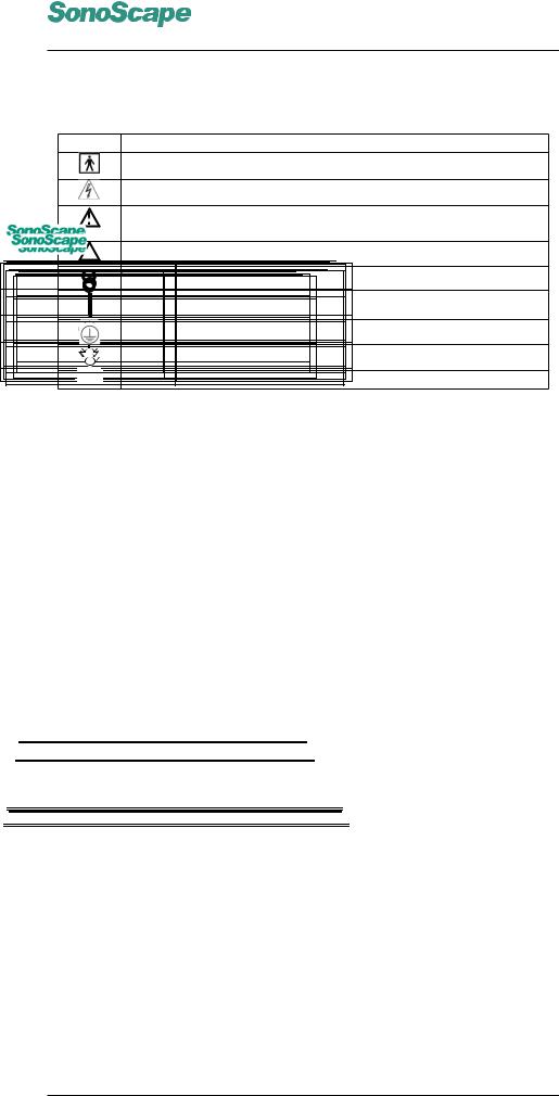
Symbol Description
Insulated patient application part (Type BF)
Dangerous electric voltage
Warning! Follow these instructions to avoid personal injury or system damage.
SSI-8000 MobileDigitalColorDopplerUltrasoundSystem |
to avoid system damage. |
|||
SSI-8000 MobileAttention!DigitalColorFollowDopplerler Ultrasoundthese instructionsSystemSystem |
||||
SSI-8000 Mobile Digital Color Doppler Ultrasound System |
|
|||
|
|
|
ServiceManual |
|
|
|
|
Service Manual |
|
|
|
Service Manual |
|
|
|
|
Service Manual |
|
|
|
Offf(MainspowerswitchOFFF) |
|
||
Off (Mains power switch OFF) |
|
|||
|
(MainsOff (Mains powerswitch OFF) |
OFF) |
|
|
|
Off (Mains |
switch OFF) |
|
|
|
On(MainspowerswitchON)ON) |
|
||
|
On (Mains power switch ON) |
ON) |
|
|
|
On On(Mains(Mains powerswitchswitchON) |
|
||
On (Mains power switch ON) |
|
|||
|
ProtectiveProtectiveearth/groundearth/groundconnectioncon. nnection. . |
|
||
|
Protective earth/g |
co ne . |
|
|
|
Protective earth/ground connection. |
|
||
Protective earth/ground connection. |
||||
|
Potential equilibrium connection |
|
|
|
|
PotentialPotentialequilibriumequilibriumconnectionconnection |
|
||
|
Potential equilibrium connection |
|
||
Potential equilibrium connection |
|
|||
|
AC |
|
|
|
|
AC AC |
|
|
|
AC |
AC |
|
|
|
AC |
|
|
|
|
Table 2.1: Table of Symbols
These symbols (icons) listed in table 2.1 are used with the equipment and/or within this manual. They serve as warnings, or for marking connections and etc.
2.3Electrical Safety
•The equipment conforms with the following regulations for electrical safety,
–IEC 60601-1: 1988+A1:1991+A2:1995, Medical Electrical Equipment Part 1: General Requirements For Safety, Class I, BF, continuous operation
–IEC 60601-2-37: 2001 + A1:2004 + A2:2005, Medical Electri-
P/N: 4720-0018-01A
cal Equipment2-4 Part 2-37: Particular Requirements For The Safety
P/N: 4720-0018-01A
2-4
Of Ultrasonic Medical Diagnostic And Monitoring Equipment
• The equipmentP/N: 4720-0018-01Aconforms with the following EMC/EMI standards:
P/N: 4720-0018-01A 2-4 2-4
IEC60601P/N:-14720-2:-00182001+A1:-01A 2004, Class A (CE)
2-4
•Degrees of protection against harmful liquid: IPX0 for the S6 system and IPX7 for the accompanying probes.
Please comply with the following rules for safety considerations:
•Properly grounding the system can prevent potential electric shock, ensure that the three-conductor AC power cord equipped with the system is plugged into an electrical outlet/receptacle marked with hospital grade. The equipment has an extra grounding point (located
P/N: 4720-0034-01A 2-2
S6 Portable Digital Color Doppler Ultrasound System
Service Manual
at the lower rear panel). To avoid loss of image quality, it is compulsory to connect this point to ground (earth).
•Potentially hazardous electrical voltage exists inside the equipment. Unauthorized personnel DONOT attempt to open the cover of the equipment.
•The equipment must not be used in the presence of inflammable gases (e.g. anesthetic gases and nitrous oxide) to avoid explosion hazard.
•Devices must be powered from a receptacle marked "hospital grade" before being connected to the system directly. In case "hospital grade" receptacles are not available, use isolation transformers instead.
 Warning!
Electrostatic discharge (ESD) may cause electric shock or damage the equipment. Observe the following precautions:
1.Prior to repairing or cleaning the equipment, ensure that the system has been turned off and the power cable unplugged.
2.The equipment must be grounded correctly during operation. Use anti-ESD spray on the ground if possible.
•The leakage current of the entire system including all auxiliary equipments must not exceed the limit as stated in IEC 60601-1.
•The equipment may interfere with or be interfered by other high frequency devices (e.g. medical lasers). Extra safety measures must be taken if other HF devices have to be used nearby.
•Use the couplant shipped with the equipment or any other couplant recommended by SonoScape. Use any unrecommended couplant may damage the probe and void the warranty.
2.4Mechanical Safety
1.Prior to using the equipment, place it horizontally and lock the wheels.
2.Take care when moving the equipment. Failure to follow the precautions listed below could result in injury, uncontrolled motion and costly damage.
Take the following precautions before transporting the system:
1)Ensure that the system is powered off and with power cable unplugged.
P/N: 4720-0034-01A 2-3

S6 Portable Digital Color Doppler Ultrasound System
Service Manual
2)Disconnect all the probes from the system and place them in their carrying case.
3)Ensure that all the peripherals and auxiliary devices have been disconnected from the system.
4)If you are moving the docking cart together with the S6 system, unlock the wheels.
5)Now you can hold the handle and push the system to the destined place.
If the system is to be transported for long distance, take the following precautions as well:
6)It’s highly recommended to backup the critical data (e.g. patient data and images) to a DVD/CD or hardcopy.
7)Ensure that the system is well prepared and packed in its original packaging before transporting.
8)Place the system upwards, and ensure that it is firmly secured while inside the vehicle during transport.
 Warning!
Avoid collisions and excessive vibrations to prevent data loss or system malfunction.
Never move the equipment which is still operating.
Environmental Conditions for Transportation:
Relative Humidity: 20% to 90%, no condensation
Temperature: -20°C to 55°C
Barometric Pressure: 700 to 1060hPa
2.5Human Safety
Modern diagnostic ultrasound system has been proved to be safe for daily diagnostic usage, however, only the well trained/educated medical personnel should operate the equipment. The ALARA (As Low As Reasonably Achievable) principle must be observed. The following are some more detailed guidelines on safety use of the equipment.
•Keep the power levels and the exposure time as low as possible, as long as a satisfactory diagnosis has been achieved.
•Use the freeze function or move the probe away from the patient while not scanning.
•Do not rest the transducer on the skin surface when not scanning.
P/N: 4720-0034-01A 2-4

S6 Portable Digital Color Doppler Ultrasound System
Service Manual
•The imaging system of S6 is based on Doppler and Color Doppler Imaging. The output power of the ultrasound is lower than the limits as required by the standard IEC 60601-1.
P/N: 4720-0034-01A 2-5

S6 Portable Digital Color Doppler Ultrasound System
Service Manual
P/N: 4720-0034-01A 2-6

S6 Portable Digital Color Doppler Ultrasound System
Service Manual
Chapter 3
Description of the System
3.1Product Description
The S6 is a professional, general purpose portable color Doppler diagnostic ultrasound system. It employs digital technology and fully exploits the potential of integrated circuits. The software is based on Linux system, which enhances the stability and efficiency while maintains the portability. The user interface has been optimized for ease of use. The imaging system can be adjusted during the scanning process; while for advanced users, the system configurations can be changed quite intuitively.
A wide range of probes make the system suitable for many applications. To keep the system up to date, the software updates are provided regularly. To enhance the system performance even more, users may also take the hardware upgrade service provided by SonoScape. There are a variety of upgradeable options available.
P/N: 4720-0034-01A 3-1

S6 Portable Digital Color Doppler Ultrasound System
Service Manual
3.2System Configuration
Overview of the S6 System
Front View
P/N: 4720-0034-01A 3-2

S6 Portable Digital Color Doppler Ultrasound System
Service Manual
Side View
1Audio Out
2 S-Video Socket
3 Two USB Ports
4 Ethernet Port
5VGA Port
P/N: 4720-0034-01A 3-3

S6 Portable Digital Color Doppler Ultrasound System
Service Manual
Rear View
1
2
3
4
5
6
7
8
9
1 |
Probe Connection Port 1 |
6 |
ECG Port |
2 |
Probe Connection Port 2 |
7 |
Equipotential point (earth) |
3 |
Video Printer Controller Port |
8 |
Power Switch |
4 |
Foot Switch Socket |
9 |
Power Input Socket |
5Video Out
3.3Applications
The S6 system, with a wide range of probes available, is extremely versatile. This section introduces the applications that the S6 system is suitable for.
6Small organs (breast, thyroid, testicle and etc.)
6Vascular
6Abdomen (liver, spleen, cholecyst, kidney and etc.)
6Obstetric
P/N: 4720-0034-01A 3-4

S6 Portable Digital Color Doppler Ultrasound System
Service Manual
6Gynecology and fertility
6Cardiology
6Urology
6Musculoskeletal
Note: The application fields are dependent on the probe in use.
 Warning!
The S6 system is not intended for ophthalmic use or any use causing the acoustic beam to pass through the eye.
3.4Operating Modes
6B Mode
6B FLOW
6Tissue Harmonic Imaging (THI)
6M Mode
6Color Doppler Imaging (CDI or CFM)
6Power Doppler Imaging (DPI)
6Directional Power Doppler Imaging (DDPI)
6Pulsed Wave Doppler Imaging (PW)
6Continuous Wave Doppler Imaging (CW)
6Tissue Doppler Imaging (TDI)
3.5Combined Modes
The system provides the following Duplex modes with some in dual display format.
Notations: Left means left screen, Up means upper screen. Similar for Right and Down, e.g., Left B+COLOR, Right B implies that the left screen is of duplex mode, B and CFM, and the right screen is of B mode.
6Left B, Right B
6Left B+COLOR, Right B;
6Left B+COLOR, Right B+COLOR
P/N: 4720-0034-01A 3-5

S6 Portable Digital Color Doppler Ultrasound System
Service Manual
6Up B, Down M
6Up B, Down PW/CW (real time)
6Up B+COLOR,Down PW/CW
6Up B+COLOR, Down PW/CW (real time)
6Up B+COLOR, Down PW/CW (real-time refreshing)
6Color+M
3.6Scanning Modes
6Electronic linear array scanning
6Sector curved array (convex) scanning
6Sector phased array scanning
6Trapezoid linear scanning
3.7Adjustable Parameters
Users can change these parameters during the scanning process to get the best image quality.
3.7.1B Mode
Image Parameters:
6Bandwidth: 1 to 15MHz
6Maximum Depth: 32.9cm
6Sector Width/Angle: 10 to 193 degrees
6Sector Position: adjustable in imaging area
6Zoom: magnification factor>10
6Power: 1% to 100%
62D Gain Range: 1 to 255
6TGC: adjustable for 8 different depth
6Sound Volume Adjustable
6Focal Zones: 1 to 9 focal zones may be chosen, with focal distance adjustable.
P/N: 4720-0034-01A 3-6
S6 Portable Digital Color Doppler Ultrasound System
Service Manual
6Persistence range: from 0 to 95, may vary with the probes
6Line Density: 3 level adjustable (high/medium/low)
6Chroma: 13 different colors available
6Adaptive Image Fusion: 6 level adjustable
6Tissue Characteristic Index: adjustable from 1400 to 1700
6Image Orientation: flip vertically and/or horizontally
3.7.2Spectral Doppler (PW/CW)
Image/Video Parameters
6Video inversion
6Flow Inversion
6Sweep Speed: 4 level adjustable
Signal Processing
6Dynamic Range: 5 level adjustable
6Chroma: 5 different colors available
6D Gain: adjustable from 1 to 255
6Doppler Angle Correction: adjustable from -80 to 80 degrees
6Sound Volume Adjustable
3.7.3Color Doppler and Power Doppler
Signal Processing
6D Gain: adjustable from 1 to 255
6Persistence Range: 0 to 80 (also depends on the probe in use.)
6Color Mapping: 4 options available
6B-Reject Range: from 0 to 255
6Baseline: 31 level adjustable.
P/N: 4720-0034-01A 3-7

S6 Portable Digital Color Doppler Ultrasound System
Service Manual
3.7.4Archive and Backup
6160G HDD (Hard Disk Drive)
6Image/Video Format: The system supports local format (PPM and CIN) and PC format (JPEG, BMP, TIF, AVI and WMV) and offers the function of conversion from local format to PC format.
6Cine Playback: More than 1 minute video supported.
6Accessing local cine files remotely through Ethernet is supported.
6Data storage using external disks (USB and DVD/CD) is supported.
6Video output: S-VIDEO/ VGA
3.8Measurements and Calculations
Measurements Functionality
6Measurements can be performed either during real-time scanning or in freeze mode.
Measurements and Calculations for 2D Image
6 Length measurements: straight line, ellipse and perimeter of any other arbitrary shapes
6Area measurements: ellipse, rectangular and area of any other arbitrary shapes
6Volume measurements
6Doppler area
6Calculation and measurement in gynecology and fertility applications.
6LV (Left-Ventricular) measurements and calculations
Available LV Calculation Methods:
YSingle Plane Ellipse
YBiplane Ellipse
YBullet
YSimpson
YCube
YTeichholz
YGibson
P/N: 4720-0034-01A 3-8

S6 Portable Digital Color Doppler Ultrasound System
Service Manual
M Mode
6Distance
6Time
6Slop
6HR (Heart Rate)
6LV (Left-Ventricular) measurements and calculations
Available LV Calculation Methods:
YCUBE
YTEICHHOLZ
YGIBSON
YMitral Valve
YAortic Valve
4D Analysis Software
Doppler Image
6 Length measurements: straight line, perimeter of ellipse and any other arbitrary shapes.
6Area measurements: area of rectangular, ellipse and any other arbitrary shapes.
6Blood flow velocity and acceleration
6Time
6Cardiac measurements: Mitral Valve, Aortic Valve, Tricuspid Valve, Pulmonary Valve, TEI index
Report Functionality
6Cardiac
6OB/GYN
6Fetal
6Vascular
6Urology
P/N: 4720-0034-01A 3-9

S6 Portable Digital Color Doppler Ultrasound System
Service Manual
P/N: 4720-0034-01A 3-10
S6 Portable Digital Color Doppler Ultrasound System
Service Manual
Chapter 4
Principle of the S6 System
4.1Introduction
This chapter provides the functional explanations of the electronics of the S6 system.
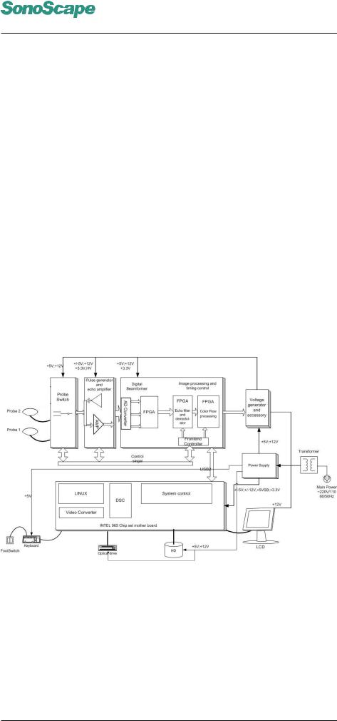
4.2System Block Diagram
Figure 4.1: Block Diagram of the S6 System
The DBTR board has the following functionalities: Control the timing and band width of the emitted ultrasound; Amplify the variable gain of the echoes; Adjust the electronic focus position, TGC, dynamic filtering, logarithmic compression, demodulation and other signal processing functions.
The echo signals are transmitted to the computer and the DBF board. The DBF board serves for extracting the Doppler signals from the echo signals, and sends the output signals to the computer system. After processed
P/N: 4720-0034-01A 4-1

S6 Portable Digital Color Doppler Ultrasound System
Service Manual
through the computer system, the signals are sent to the graphics card and then to the display (e.g. LCD monitor).
The computer system is the core control unit of S6. Following user instructions from the keyboard, it controls the operating modes and adjusts the status of the system. The computer system is also responsible for the display of diagnostic data, calendar, time and etc.
4.3Principle of Probes
The transducer provides conversions between ultrasonic and electronic signals. At the start of a scanning process, the probe first converts the electronic excitation signals to ultrasonic vibrations. The ultrasonic vibrations (or ultrasound) propagate into the body of the patient; and the echoes are picked up by the probe. Electronic signals converted from these echoes are sent back to the computer system or the DBF board for further processing. The acousto-electric conversion efficiency and the ultrasound focusing ability are the key features that are vital to the system’s performance, such as resolution, maximum scanning depth.
4.4Operating Modes
This section gives brief explanations of the principles of the scanning modes of the S6 system.
M Mode
Primarily applied in cardiology, M mode provides Time and Motion echo information derived from a stationary ultrasound beam. It records moving anatomical structures and produces subtle patterns of motion.
2D/B Mode
B mode image, also called 2D image, provides a cross sectional view of tissues. The ultrasound image is derived from the tissue echoes that received by the probe. Each echo’s intensity is mapped to a shade of gray; and the location that the echo occurs is mapped to a unique point on the screen. Except for linear array probes which produce rectangular images, most probes produce fan shaped images.
Spectral Doppler(PW/CW)
The spectral Doppler mode detects the movements of red blood cells based on the Doppler principle. The moving cells reflect the ultrasound sent by the probe. The echoes are frequency shifted (phase shift are detected for PW mode) as a result of Doppler Effect. The spectral distribution of the echoes reveals details of the blood flow: red (blue) shift implies flow away from (towards) the probe head. The pulsed wave mode (PW) is normally applied at detecting low flow velocity, while the continuous wave mode (CW) is normally for measuring high speed blood flow.
P/N: 4720-0034-01A 4-2

S6 Portable Digital Color Doppler Ultrasound System
Service Manual
Color Flow Mode (CFM)
CFM (Color Flow Mode) is also called CDI (Color Doppler Mode) sometimes. CFM combines 2D grayscale imaging with color imaging. The 2D imaging gives information on tissues; the color imaging, which uses the Doppler principle, gives information on blood flow. The output is the color image overlaid with the 2D grayscale image.
Power Doppler (DPI)
The color image in Power Doppler Imaging (DPI) is in principle different from that in CFM. DPI analyzes amplitude shift, while CFM analyzes frequency shift. The color image is overlaid onto the 2D grayscale image which gives information on tissues. DPI is capable of detecting low speed blood flow.
A high pass filter (wall filter) is used to remove the signals from stationary or slowly moving structures. Tissue motion is discriminated from blood flow by assuming that blood is moving faster than the surrounding tissue, although additional parameters may also be used to enhance the discrimination. The power in the remaining signal after wall filtering is then averaged over time (persistence) to present a steady state image of blood flow distribution.
4.5Functional Boards/Units of the S6 System
Besides the probes, the S6 system consists of the following critical functional boards/units.
6MPC board: Also called probe board. Two probes can be connected at the same time and one of them active (scanning).
6DBTR board: It has an emitting pulse synthesizer and a receiving signal preamplifier/TGC. The DBTR sends electronic signals to drive the probes and pre-amplifies the echoes.
6DBF board: It converts analog signals to digital signals and sends the signals for digital beam forming (DBF). DBF board also has scan controller, front end controller, demodulation unit and USB ports.
6DBHV board: It provides the high voltages for the pulse generator and the low voltages for other system units. The ECG and 4D motor units are also on this board.
6PC Motherboard: It is the core data processing unit of the S6 system.
6Power supply: ATX SMPS power supply. It provides stable power supply to the whole system (probes, host and LCD monitor).
6User Keyboard: hard keys, trackball, flip switches and knobs.
P/N: 4720-0034-01A 4-3

S6 Portable Digital Color Doppler Ultrasound System
Service Manual
6Monitor: 15 inch LCD
6Loudspeakers: Serve as Doppler audio device.
4.5.1Functional Block Diagram
DBTR Board |
|
|
|
|
|
|
|
|
le |
|
|
|
|
|
|
|
|
||
|
|
|
|
|
|
|
|
|
|
7500-0820-XX |
|
|
|
|
|
|
|
|
b |
|
|
|
|
|
|
|
|
C |
|
|
|
|
|
|
|
|
|
|
a |
|
|
|
|
|
|
|
|
|
r |
|
|
|
|
|
|
|
|
|
e |
|
|
|
|
|
|
|
|
Voltage |
w |
|
|
|
|
|
|
|
|
P |
|
|
|
|
|
|
|
|
|
|
o |
|
|
|
|
|
|
|
|
Conversion Board |
|
|
|
|
|
|
|
|
|
|
|
|
|
|
|
|
|
|
le |
|
|
|
|
|
|
|
|
b |
|
||
|
|
|
|
|
a |
|
|
|
|
|
|
|
|
|
C |
|
|
|
|
|
|
|
|
r |
|
|
|
|
|
|
|
|
e |
|
|
|
|
|
|
|
|
w |
|
|
|
|
|
|
|
|
o |
|
|
|
|
|
|
|
|
|
P |
|
|
|
|
|
|
|
|
Monitor
VGA Cable
KBD board |
Loudspeaker |
Loudspeakers |
||||
7500-0813-XX |
|
|
Cable |
|||
|
|
|
|
|||
|
|
|
|
|
|
|
Cable |
|
|
|
|
|
|
|
|
|
|
Fan |
|
|
IDE |
|
|
C |
|
||
|
|
|
|
le |
|
|
|
|
|
er |
ab |
|
|
|
|
w |
|
|
|
|
|
o |
|
|
|
|
|
|
P |
|
|
|
|
|
DBF Board |
USB Cable |
Motherboard |
|
7500-0821-XX |
2101-0008 |
||
|
VIDEO |
Data Cable |
|
|
OUT |
Power Cable |
|
|
ECG |
||
|
|
||
|
Data Cable |
|
|
DBHV Board |
Power Calbe |
Power Supply |
|
7500-0822-XX |
|||
|
|
PS2 Cable |
KEAA board |
Printer Cable |
Printer |
|
7500-3039-XX |
||||
|
|
|
||
|
|
|
|
|
|
F |
|
S |
|
o |
|
|
ot |
||
A |
|
||
|
S |
||
TA |
|
||
|
w |
||
|
|
i |
|
C |
|
t |
|
|
ch |
||
a |
|
||
b |
|
C |
|
l |
|
||
e |
|
ab |
|
|
|
l |
|
|
|
e |
|
|
|
|
|
Power Cable |
HDD |
|
Foot Switch |
|
|
|
|
Figure 4.2: Functional Block Diagram
4.5.2Explanations of the System Functions
The electronic pulse signals are sent to the DBTR board from the RAM of the DBF board. After processing, DBTR sends the HV signals to drive the piezo oscillator in the probe. The probe emits the ultrasonic sounds towards patient, and also picks up the echoes. The signals are then processed by the front end amplifier and the TGC, both on the DBTR board. At the same time, the DBF board converts the analog signals to the digital signals, utilizes the digital dynamic receive focusing and dynamic tracing technologies, and then demodulates. With some further processing, the signals carrying image information are transmitted to the computer through high speed USB2.0 connection. The computer processes the image data, and the tissue and/or blood flow information is displayed on the screen. The computer also takes user inputs from the keyboard, and sends the control signals to the DBF board through USB2.0 port. Peripherals and Ethernet ports are available on the Motherboard. The switching power supply for medical use provides 12V and 5V DC outputs to other system units/boards. The DBHV board supplies 90V DC and the low voltages for other digital and analog circuits.
P/N: 4720-0034-01A 4-4

S6 Portable Digital Color Doppler Ultrasound System
Service Manual
4.6Part List
Part No. |
Name |
Quantity |
Description |
|
7500-0826 |
MPC |
1 |
Probe connection PCB board |
|
|
|
|
|
|
7500-0820 |
DBTR |
1 |
Emission/Reception PCB board |
|
|
|
|
|
|
|
|
|
PCB board for receiving digital |
|
7500-0821 |
DBF |
1 |
beam forming and signal pro- |
|
|
|
|
cessing |
|
|
|
|
|
|
7500-0822 |
DBHV |
1 |
PCB board providing high volt- |
|
ages |
||||
|
|
|
||
|
|
|
|
|
7500-0815 |
KBD |
1 |
Keyboard PCB board |
|
|
|
|
|
|
|
|
|
KEAA board serves as a hub |
|
7500-3039 |
KEAA |
1 |
for interconnecting other PCB |
|
|
|
|
boards. |
|
|
|
|
|
|
|
|
|
It is the central control unit for |
|
2101-0008 |
PC Motherboard |
1 |
data processing and video/audio |
|
|
|
|
output. |
|
|
|
|
|
|
2101-0152 |
HDD |
1 |
160G hard disk drive |
|
|
|
|
|
|
3900-0012 |
LCD Monitor |
1 |
Designed exclusively for medical |
|
use |
||||
|
|
|
||
|
|
|
|
|
NA |
Voltage Inversion |
1 |
Provides high voltage source for |
|
Board |
LCD. |
|||
|
|
|||
|
|
|
|
P/N: 4720-0034-01A 4-5

S6 Portable Digital Color Doppler Ultrasound System
Service Manual
P/N: 4720-0034-01A 4-6
 Loading...