

Sonosax SX-ST,SX-VT User Manual

USER MANUAL
PROFESSIONAL MIXING CONSOLE
SONOSAX
SX-ST / SX-VT
Audio equipment manufacturer
SONOSAX SAS S.A.
Ch. de la Naz 38
CH-1052 Le Mont s/Lausanne
SWITZERLAND
Tel: +41 21 651 0101
Fax: +41 21 651 0109
Web: www.sonosax.ch
www.sonosax.com
Email: sonosax@sonosax.ch
Version: DOC-1.2
Printed in Switzerland, May 2006

SX-ST / SX-SV User Manual page 2
TABLE OF CONTENTS
INTRODUCTION................................................................................................................................................5
Key Features 5
1. GENERAL DESCRIPTION........................................................................................................................6
1.1 SONOSAX SX-ST series............................................................................................................................................. 6
1.2 SONOSAX SX-VT series ............................................................................................................................................ 6
1.2.1 VCA and Compressor options............................................................................................................................... 6
2. INSTALLATION.........................................................................................................................................7
2.1 Safety Instructions.............................................................................................................................................. 7
2.2 Battery Power Mode (SX-ST Series only)...................................................................................................... 8
2.2.1 Removing the battery compartment...................................................................................................................... 8
2.2.2 Opening the battery compartment.........................................................................................................................8
2.2.3 Closing the battery compartment .......................................................................................................................... 9
2.2.4 Batteries charger (option for SX-ST Series only) .................................................................................................. 9
2.3 External DC Power Mode (SX-ST Series only).............................................................................................. 9
2.4 AC Power Mode (SX-VT Series only)........................................................................................................... 10
2.4.1 Operating voltage switch..................................................................................................................................... 10
3. OPERATING INSTRUCTIONS ...............................................................................................................10
3.1 Switching ON your SONOSAX SX-ST / SX-VT mixer......................................................................................... 10
3.2 Using an External DC Power Supply............................................................................................................... 10
3.3 Battery Test....................................................................................................................................................... 10
3.4 Low Battery Alarm............................................................................................................................................ 10
3.5 Automatic changeover of power source (SX-ST Series only)................................................................... 10
4. MIC / LINE INPUT MODULE...................................................................................................................11
4.1 Input Select Switch........................................................................................................................................... 12
4.2 Mic power switch.............................................................................................................................................. 12
4.3 ∅ Phase reversal switch................................................................................................................................... 12
4.4 Gain Controls.................................................................................................................................................... 12
4.5 LF Cut and Equalizer........................................................................................................................................ 13
4.6 Mix busses 1 to 8 assignment ......................................................................................................................... 14
4.6.1 Pan Pot (Panoramic Potentiometer) ................................................................................................................... 14
4.7 AUX Sends 1 to 4.............................................................................................................................................. 14
4.7.1 AUX 1 to 4 PRE/OFF/POST switches................................................................................................................ 14
4.8 Dual Peak Level Meters.................................................................................................................................... 14
4.9 Limiter ( non VCA version only )................................................................................................................ 15
4.9.1 Limiter LED......................................................................................................................................................... 15
4.10 ON Push button ................................................................................................................................................ 15
4.10.1 ON status LED............................................................................................................................................... 15
4.11 Channel Fader................................................................................................................................................... 15
4.11.1 Level switch 12 / 24 (SX-ST series only)....................................................................................................... 15
4.12 Channel Power switch (SX-ST series only)................................................................................................. 16

SX-ST / SX-SV User Manual page 3
4.13 PFL/AFL push button ....................................................................................................................................... 16
4.13.1 P/A LED......................................................................................................................................................... 16
4.14 VCA's Group Selector (SX-VT Series with VCA input module only) .................................................... 16
4.15 Compressor (SX-VT series with VCA input module only)..................................................................... 16
4.15.1 Threshold....................................................................................................................................................... 16
4.15.2 Ratio...............................................................................................................................................................16
4.15.3 Compressor LED............................................................................................................................................16
4.16 On Air signaling ( SX-VT serie only )........................................................................................................... 17
4.17 MUTE function .................................................................................................................................................. 17
5. STEREO LINE INPUT MODULE ............................................................................................................18
5.1 Left & Right Gain Control...................................................................................................... ........................... 19
5.2 MONO selector.................................................................................................................................................. 19
5.3 Stereo Equalizer................................................................................................................................................ 19
5.4 AUX Sends 1 to 4.............................................................................................................................................. 19
5.4.1 AUX 1 to 4 PRE/OFF/POST switches................................................................................................................ 19
5.5 Dual Peak Level Meters.................................................................................................................................... 19
5.6 Channel Fader................................................................................................................................................... 20
5.7 Balance Left – Right ......................................................................................................................................... 20
5.8 Mix busses 1/2 to 7/8 assignments ................................................................................................................. 20
5.9 ON Push button ................................................................................................................................................ 20
5.9.1 ON status LED.................................................................................................................................................... 20
5.10 Remote............................................................................................................................................................... 21
5.11 PFL/AFL push button ....................................................................................................................................... 21
5.11.1 P/A LED......................................................................................................................................................... 21
5.12 VCA's Group Selector ( optional on SX-VT Series only) ......................................................................... 21
6. 8 CHANNELS A/D CONVERTER..........................................................................................................22
7. MASTER & MONITORING MODULE.....................................................................................................23
7.1 Meters ................................................................................................................................................................ 24
7.1.1 ST / M / Low Batt switch ..................................................................................................................................... 24
7.1.2 Meter's Backlight switch...................................................................................................................................... 24
7.1.3 LEDS switches.................................................................................................................................................... 24
7.1.4 ON AIR and MUTE Leds ( SX-VT series only )................................................................................................... 24
7.2 Talkback/SLATE and Oscillator....................................................................................................................... 25
7.2.1 MIC/OSC/FIX switch........................................................................................................................................... 25
7.3 PFL/AFL/SOLO and operating mode............................................................................................................... 25
7.3.1 Normal/Reset switch........................................................................................................................................... 25
7.4 Power ON/OFF .................................................................................................................................................. 25
7.5 Returns 1 to 8.................................................................................................................................................... 25
7.5.1 Return Mix master level ...................................................................................................................................... 25
7.5.2 P/A RET push button .......................................................................................................................................... 25
7.6 Monitoring ......................................................................................................................................................... 26
7.6.1 Monitor Source Selector ..................................................................................................................................... 26
7.6.2 Monitor Mode selector ........................................................................................................................................ 26
7.6.3 Phones Level 1 to 3 ............................................................................................................................................ 26
7.7 Communication and Private Lines.................................................................................................................. 26

SX-ST / SX-SV User Manual page 4
7.7.1 Mic 1 to 3 ............................................................................................................................................................ 26
7.8 Groups and Aux Master Sections.................................................................................................................... 27
7.8.1 Group Master rotary faders................................................................................................................................. 27
7.8.2 Master Auxiliary sends 1 to 4.............................................................................................................................. 27
7.8.3 Peak Level Meters .............................................................................................................................................. 27
7.8.4 P/A push buttons................................................................................................................................................. 27
7.8.5 P/A Led's............................................................................................................................................................. 27
7.8.6 Talkback / Off / Return → switches..................................................................................................................... 27
8. SPECIFICATIONS...................................................................................................................................28

SX-ST / SX-SV User Manual page 5
INTRODUCTION
Congratulations, by purchasing your SONOSAX SX-ST or SX-VT professional mixing console, you have
acquired a product of the highest quality, manufactured to deliver many years of outstanding performances.
The SONOSAX SX-ST or SX-VT Series are the most compact modular mixing consoles on the market.
Meanwhile their reduced size, they offer a maximum of possibilities to suit each user needs, with unequalled
characteristics.
As with all SONOSAX products, the SX-ST and SX-VT series are built without any compromise in quality. Our
25 years of experience have helped us to develop and build this mixer which is designed to last a minimum of
12 to 15 years. The reliability of the SONOSAX SX-ST or SX-VT is due to a high-tech design, the choice of the
best components available, a meticulous hand assembly and a severe quality control.
Each stage of the modules has been extensively studied to give the highest in quality and performances. The
result of the research and development is an ergonomic mixing console with extraordinary characteristics.
Key Features
• Compact and fully modular construction
• Un-compromised choice of components
• Ultra-low noise mic preamps with +48V phantom power available on all input channels
• Electronically balanced, transformer less inputs and outputs
• Wide bandwidth10Hz to 200kHz, suitable for SACD and next converters generations
• High dynamic range and large headroom
• Direct Outputs selectable Pre-EQ, Post-EQ or Post Fader
• 8 Groups individually selectable Pre or Post Pan
• 4 Auxiliaries individually selectable Pre or Post Fader
• Limiter on each input channel
• High quality conductive plastic linear fader
• Dual peak meters on each input for Pre and Post Fader level indications
• Triple Monitoring section with 2 Private Lines for communications
• Large scale level-meter indicators switch able to level and phase correlation meter
• Internal 8 channels of high quality A to D converter ( optional )
• Integrated 8 track Hard disk and Compact flash Card recorder ( optional )
• Compact size and low weight
• Low consumption
The information contained in this manual is subject to change without notice.
All specifications mentioned in this manual apply to standard models only.
SONOSAX SAS SA reserves the right to modify these characteristics at any time without prior notice.
No part of this manual may be reproduced or transmitted in any form or by any means, electronic or
mechanical including photocopying and recording of any kind, for any purpose, without the express
written permission of SONOSAX SAS SA.
© 2003 SONOSAX SAS SA, Ch. de la Naz 38, 1052 Le Mont s/Lausanne, Switzerland.
Phone: +41 21 651 0101, Fax: +41 21 651 0109, Email: sonosax@sonosax.ch Web: www.sonosax.ch

SX-ST / SX-SV User Manual page 6
1. GENERAL DESCRIPTION
The SONOSAX SX-ST and SX-VT Series is a line of extremely compact, portable, self-contained mixing
consoles, designed for professional mobile and studio applications.
Built in a strong, rugged and anodised aluminium chassis, the SONOSAX SX-ST and SX-VT Series provide the
best solution whenever top performances, reduced size and low consumption are important.
Due to its versatility, the SONOSAX SX-ST and SX-VT are the ideal mixing consoles for numerous applications,
such as:
• video, television and cinema production and post-production
• fixed and mobile recording studio and broadcast
• OB Van
• digital or analogue sound recording
• very high quality sound systems for concert halls, theaters, etc.
The SONOSAX SX-ST and SX-VT have been created taking into consideration the possibility of working with
digital sound recording, as well as synchronization and automation with other existing or future equipments.
1.1 SONOSAX SX-ST series
Battery or DC powered, the SX-ST series are available with configurations of up to 10 inputs modules. The
Master & Monitoring module provides with 8 Master outputs, 4 Auxiliaries, 3 independent Monitoring selectors,
two independent Private Line for communication
Two frame sizes for the SX-ST series are available:
SX-ST8D, for up to 8 input modules with space provided for optional Digital or Recorder module
SX-ST10, for up to 10 input modules, or up to 9 inputs and one Digital or Recorder module
The SX-ST series being fully modular you can purchase with a few number of modules and add more modules
or options at a later date.
1.2 SONOSAX SX-VT series
The SX-VT series uses the same technologies as the SX-ST series but is available with configurations from 12 to
48 inputs. Thus, the technology and the modules are similar, the battery pack have been removed as the SX-VT
series can only be DC powered from its external main to DC adapter or from a suitable DC power source such
as a large battery bank.
The supplied AC to DC adapter has a voltage range from 100 to 260V AC, 47Hz to 64Hz allowing the use of
the console worldwide without any modification. For OB-Van applications, we can provide a special power
supply to power the mixer from the 12V or 24 V vehicle battery bank.
The SX-VT series comes with the same Master & Monitoring module as the SX-VT.
Each SONOSAX SX-VT mixing console is composed of standard modules combined and assembled according
to the needs and desires of the user. In this way, it is adapted as closely as possible to the required
specifications and at the same time, remains expandable.
1.2.1 VCA and Compressor options
As an option, the SX-VT series can be equipped with VCA's (voltage controlled amplifier) input modules with
Compressor and optional VCA grouping.
A DB25 computer type connector allows control of the VCA with an external DC voltage source (for example a
video editor or an automation system) thus allowing external level control for each input.
The compressor is of a very particular type and does not have the “pumping” effect so often found with this kind
of circuitry. The user is therefore assured at all times, particularly when working with digital systems, that there
will be no saturation that could lead to catastrophic effects.
NOTE: When used with external controllers, faders must be positioned at 0 dB.
Due to power consumption of VCA's, these options are not available on the SX-ST series

SX-ST / SX-SV User Manual page 7
2. INSTALLATION
2.1 Safety Instructions
• Read all the safety and operation instructions before operating the SX-ST / SX-VT console and its
power supply.
• Keep the instructions for further reference.
• Follow all warnings, notes and instructions in this operation manual.
• Do not use the SX-ST / SX-VT console and its power supply near water, avoid moisture.
• Keep the SX-ST / SX-VT console and its power supply away from heat sources such as radiators or
other devices that produce heat.
• Connect the SX-ST / SX-VT console only to the original power supply included with the console or to
one with same characteristics as described in these instructions.
• Route power supply cords so that they are not likely to be walked on or pinched by items placed on or
against them, paying particular attention to cords at plugs, inlets and the point where they exit the
console. Keep power cords away from audio cords.
• Do not drop objects or spill liquids onto the SX-ST / SX-VT console and its power supply.
• The SX-ST / SX-VT console and its power supply should only be serviced by qualified service
personnel. Please contact factory or your nearest SONOSAX authorized reseller.
• Do not defeat the grounding or polarization of the SX-ST / SX-VT console or its power supply.
• Line voltage selectors should only be set and equipped with a proper plug for alternate voltage by a
qualified service technician.
• To reduce the risk of fire or electric shock, do not expose this appliance to rain or moisture.
• Internal settings must be executed by an authorized SONOSAX distributor or reseller. There is no user
serviceable parts inside the mixer. Damage due to manipulations inside the unit cancels the SONOSAX
warranty immediately..
SX-ST / SX-SV User Manual page 8
2.2 Battery Power Mode (SX-ST Series only)
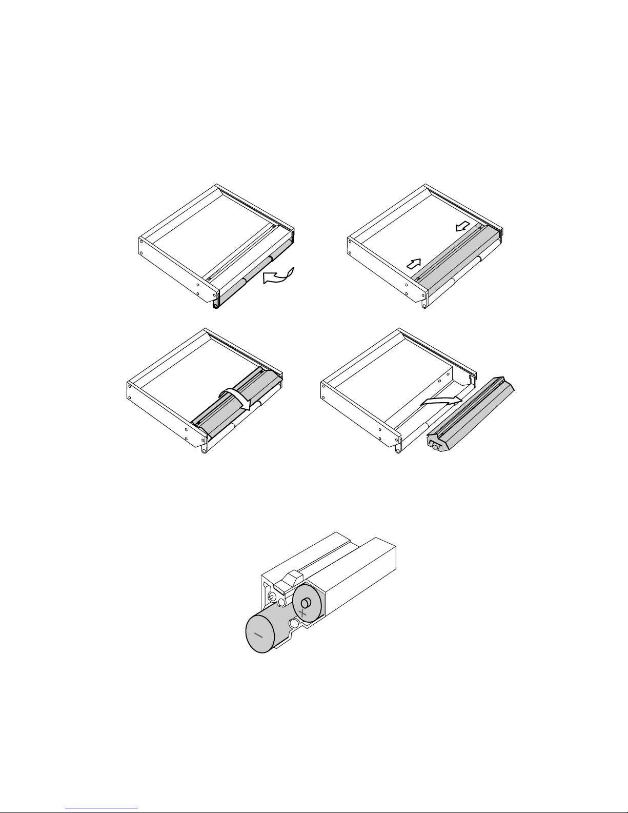
2.2.1 Removing the battery compartment
Remove the battery pack by releasing the two slide-locks, tilting the compartment diagonally towards you and
lifting it out.
IMPORTANT: Keep the slide-locks pressed towards the centre till the battery compartment is completely lifted
out of the mixer.
2.2.2 Opening the battery compartment
The battery compartment may now be opened by un-tightening the screw on the left side. Remove the plastic
side cover and insert 12 alkaline D-cells or 12 rechargeable Nickel-Cadmium (NiCd) or Nickel-Metal-Hydride
(NiMH) batteries.
NOTE: On the left side of the battery compartment, you will find the hexagonal wrench (2 mm) which
enable you to completely disassemble the SX-ST without using any other tool.
WARNING: Never leave discharged batteries in your SX-ST. Make sure that your SX-ST only contains
rechargeable NiCd or NiMH batteries before charging. When using dry cells, use only
professional alkaline batteries to ensure optimal autonomy. Also check the manufacture date
SX-ST / SX-SV User Manual page 9
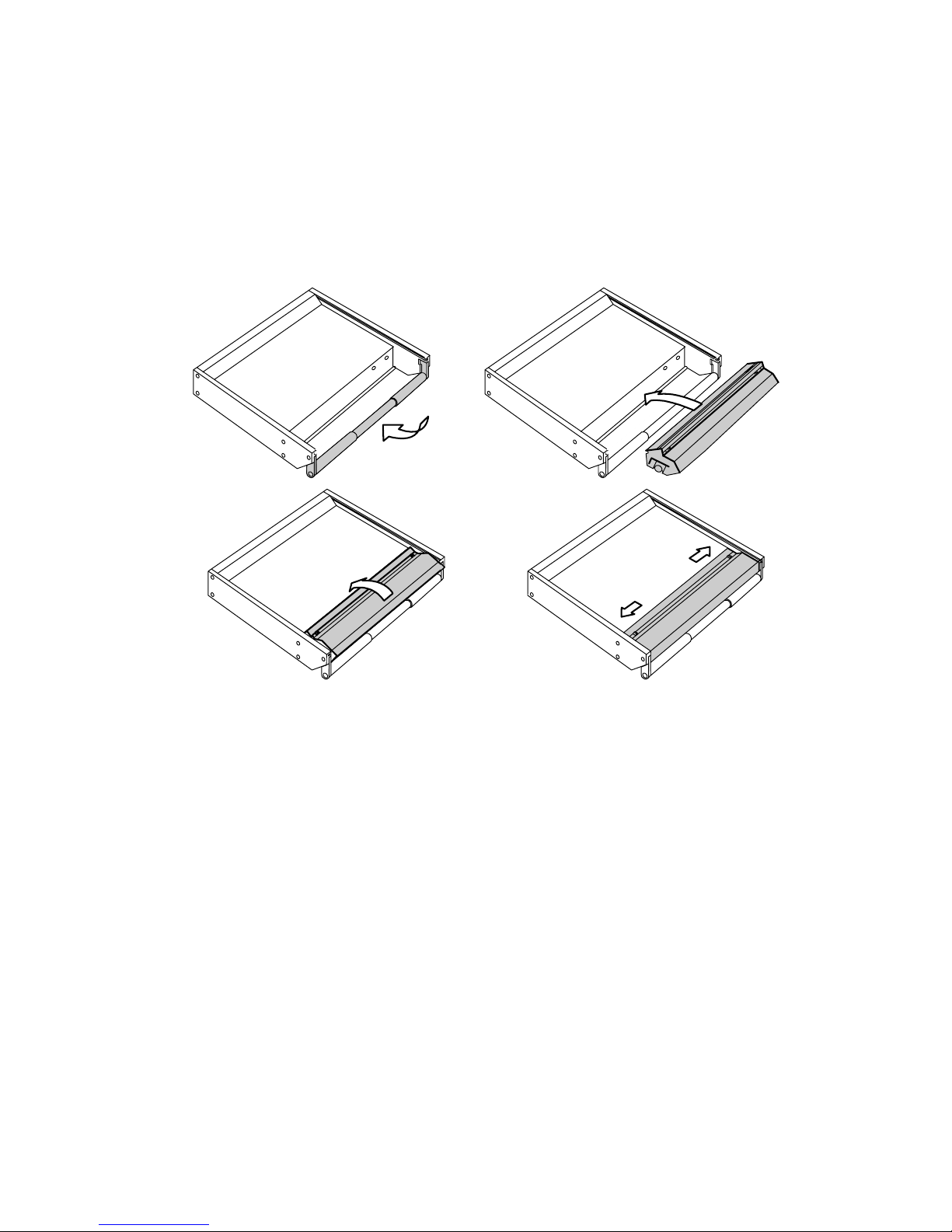
2.2.3 Closing the battery compartment
Replace the plastic side cover and tighten the screw. ( Do not over tighten )
NOTE: Certain D-Cells are longer than standard D-Cell batteries and slight difficulty may be found in
closing the compartment if such batteries are used. Your nearest SONOSAX agent or the
manufacturer in Switzerland can provide assistance if a problem arise due to this difference
in length.
Replace the battery compartment while holding in the slide-locks and make sure the power contacts are
correctly positioned. The battery compartment is in place when the slide-locks return easily to their original
position.
2.2.4 Batteries charger (option for SX-ST Series only)
An external NiCd or NiMH batteries charger is available for the SX-ST Series. (part nr SX 008415 )
You do not need to remove the cells from the battery tray to individually recharge the batteries.
A connector located at the right side of the battery tray is provided to recharge all 12 cells at once. Simply
remove the battery compartment as described at section 2.2.1 and connect appropriate charger to the battery
pack.
WARNINGS:
- Never attempt to charge alkaline D-Cell batteries ( high risk of explosion ! )
- Charger must be suitable for 14,4 V batteries
- Make sure that your NiCd or NiMh batteries accept high current charge when using a fast charger
2.3 External DC Power Mode (SX-ST Series only)
The SONOSAX SX-ST mixer can be powered from an external 10,5 to 18 Volts regulated DC power supply,
capable of delivering at least 2.5A. The average power consumption is approximately 2A.
The SX-ST series is supplied with an auto-ranging power supply 100 to 240 VAC 50 or 60 Hertz, that can be
used worldwide without modification or setting changes.
The DC power supply input connector (XLR 4 pin, SONOSAX Part Number xxxxxxxx) is located on the rear
panel of the SX-ST mixer. Pin 1 is 0V or negative / Pin 4 is positive +10,5 to +18VDC

SX-ST / SX-SV User Manual page 10
2.4 AC Power Mode (SX-VT Series only)
The connection of mains the power supply is made by using a mains cable and a standard IEC receptacle. It
meets all of the international safety certification requirements.
Please make sure that the unit has a proper ground connection. For your own safety, it is advisable not to
remove the ground connection at the power supply or fail to make this connection at all.
2.4.1 Operating voltage switch
The external Main Power Supply is designed for an AC voltage range from 100 to 260V AC, 40Hz to 60Hz
without any modification.
3. OPERATING INSTRUCTIONS
3.1 Switching ON your SONOSAX SX-ST / SX-VT mixer
The POWER ON switch is located on the Master Module at the right side of the lower level meter. Turn to
Power position to activate the internal DC/DC Converter that will power up your mixer. The green LED should lit
up within 2 to 3 seconds, if not:
• Check that batteries have been inserted correctly inside the battery compartment.
• If necessary change the batteries.
• Check the external DC Power supply
3.2 Using an External DC Power Supply
Apply External DC Voltage from 10,5 to 18VDC (see 1.6) between points 4 (+Vdc) and 1 (0V) of the XLR-4
connector. The external DC power supply must be regulated and capable to deliver a continuous current of at
least 2,5 Amp
3.3 Battery Test
When the BATT TEST momentary switch, located below the Level Meters, is depressed, the lower level meter
will indicate the average charge per cell (minimum 1V, maximum 1.5V).
3.4 Low Battery Alarm
When the average charge per cell reaches 1.05V, the Low Batt LED will automatically start to blink. This alarm
means that about 10 to 20 minutes remain before the mixer automatically turns off. This auto-stop protects the
accumulators from excessive discharge.
3.5 Automatic changeover of power source (SX-ST Series only)
The internal DC/DC converter circuitry is designed to automatically changeover between the internal batteries
and the external DC power supply. You do not need to power OFF the SX-ST to change the power source.
While powering up the mixer, when both the external DC power supply is connected and the internal batteries
are installed, the internal DC/DC converter will first connect to the external DC power supply even if the external
DC voltage is lower than the battery pack voltage. If the external power voltage drops below 10.5 Volts then the
DC/DC converter will automatically switch to the battery pack
When the voltage of the internal batteries drops below 1.00V per cell the DC/DC converter will switch
automatically to the external DC power supply if connected to the mixer after the power up procedure.
NOTE: there is absolutely no noise, pops or clicks during a power source changeover
 Loading...