

Page 1

PROFESSIONAL AUDIO
MIXING CONSOLE
SONOSAX
SX-ES64
User manual
audio equipment manufacturer
SONOSAX SAS S.A.
Ch. de la Naz 38
1052 Le Mont s/Lausanne
SUISSE
Tel: +41 21 651 0101
Fax: +41 21 651 0109
Web: www.sonosax.ch
Email: [email protected]
Version 1.0 / August 2009
Page 2

TABLE OF CONTENT
1. INTRODUCTION .................................................................................................................................................. 3
2. APPLICATIONS...................................................................................................................................................3
2.1 MAIN FEATURES ................................................................................................................................................ 3
2.2 OPTIONS AND ACCESSORIES.......................................................................................................................... 4
2.2.1 External Power Supply ......................................................................................................................................... 4
2.2.2 Optional Output connectors .................................................................................................................................. 4
2.3 SAFETY INSTRUCTIONS.................................................................................................................................... 4
3. POWERING ON THE UNIT.................................................................................................................................. 5
3.1.1 Power from internal batteries................................................................................................................................ 5
3.1.2 Battery charge indicator........................................................................................................................................ 5
3.1.3 Powering from external DC power supply............................................................................................................. 6
3.1.4 Automatic changeover of the DC power source ................................................................................................... 6
4. MIC/LINE INPUT SECTION ................................................................................................................................. 7
4.1.1 Mic/Line Inputs [ IN1 to IN6 ] ................................................................................................................................ 8
4.1.2 Phantom power [ 48V ] ......................................................................................................................................... 8
4.1.3 Pre-LF Cut Filter [ LF Cut ] .................................................................................................................................. 8
4.1.4 Phase reversal [ Ø ].............................................................................................................................................. 8
4.1.5 Input GAIN setting [ MID – LO - HI ] .................................................................................................................... 9
4.1.6 Input Limiters ........................................................................................................................................................ 9
4.1.7 Sweep LF-Cut [LF CUT] ....................................................................................................................................... 9
4.1.8 Optional 3 bands semi-parametric Equalizer [EQ].............................................................................................. 10
4.1.9 3 Leds peak-meter.............................................................................................................................................. 10
4.1.10 Pre-Fader Listening [PFL]................................................................................................................................... 11
4.1.11 Channel fader ..................................................................................................................................................... 11
4.2 MIX BUS ASSIGNEMENT ROUTING SWITCHES [ 1 TO 4 ]............................................................................ 12
4.2.1 Pan Pot (Panoramic Potentiometer) ................................................................................................................... 12
5. MASTER AND MONITORING SECTION .......................................................................................................... 13
5.1.1 Summing amplifiers [Master] .............................................................................................................................. 14
5.1.2 Switches [ SLATE – Off – RET ] ......................................................................................................................... 14
5.1.3 Group Monitoring [ MON ].................................................................................................................................. 14
5.2 SLATE MIC AND OSCILLATOR [ MIC OSC FIX ] AND [ SLATE ] KEY..........................................................15
5.3 RETURNS 1 TO 4 [ RET ]................................................................................................................................. 15
5.3.1 Return Mix Master level...................................................................................................................................... 15
5.3.2 Return's Pre-Fader Listening [ PFL ] ................................................................................................................. 15
5.4 MONITORING .................................................................................................................................................... 16
5.4.1 Main Monitor source selector [ MON ] ................................................................................................................ 16
5.4.2 Monitor Mode selector [ EXT L R ST M MS MS/M] ............................................................................................ 16
5.4.3 Headphone level [ PHONE1 ] ............................................................................................................................. 16
5.4.4 Command switch [ COM ].................................................................................................................................. 16
5.4.5 Potentiometer [ MIC1 ]....................................................................................................................................... 16
5.4.6 Secondary Monitor selector [ 1-2 3-4 RET EXT - ] .......................................................................................... 17
5.4.7 Headphone level [ PHONE2 ] ............................................................................................................................. 17
5.4.8 Touche [ PL1 ] ................................................................................................................................................... 17
5.4.9 Potentiomètre [ MIC2 ]....................................................................................................................................... 17
5.4.10 Headphone outputs [ PHONE1 et PHONE 2 ] .................................................................................................... 17
5.5 LEDS PEAK-METERS [ PEAK-METERS ]........................................................................................................ 18
6. DIGITAL OUTPUT [ AES ]................................................................................................................................. 19
6.1.1 Sampling frequencies [ 96 EXT 48 ] ................................................................................................................... 19
7. ADDENDUM....................................................................................................................................................... 20
7.1.1 Main connectors wiring diagrams ....................................................................................................................... 20
7.1.2 Optional connectors [OPTION] ........................................................................................................................... 22
7.2 BLOC DIAGRAMM ............................................................................................................................................ 23
8. SPECIFICATIONS ............................................................................................................................................. 25
9. TIPS ON USING YOUR MIXER ......................................................................................................................... 27
User manual SONOSAX SX-ES64 Page 2 of 27
Page 3

1. INTRODUCTION
Congratulations, by choosing the professional mixing console SONOSAX SX-ES64 you have acquired a high
quality product, designed and built to last for many years with outstanding performances.
The SONOSAX SX-ES64 is one of the most compact mixing consoles on the market. Despite its reduced size;
it provides with numerous features to suit each user's requirements.
As for any SONOSAX products, the SX-ES64 mixing console is built without any compromise in quality. Our
30 years of experience have helped us to develop and build this console which is designed to have a lifespan
of at least 12 to 15 years. The reliability of SONOSAX product is the result of a high technology design, a
selection of the best available components, a meticulous hand assembly and a severe quality control.
Each of its circuits has been intensively studied to reach the highest level of performance and the lower
possible power consumption. The end result of these research and development is an ergonomic mixing
console with outstanding performances, yet at an affordable price.
To offer a mixer that not only suits to user's technical requirements but also adapted to each budget, some
features normally found in standard on other mixers are offered as options on the SONOSAX SX-ES64
The information and instructions contained in this manual are necessary to ensure safe operations of your
equipment and to maintain it in good working condition; please read it carefully.
2. APPLICATIONS
The SONOSAX SX-ES64 is an extremely compact mixing console, lightweight and easily transportable.
Built in a strong, rugged, anodised aluminium housing, it provides with numerous features to meet the needs
of professionals in mobile and studio applications.
The SONOSAX SX-ES64 mixer is an ideal solution in almost all applications where performance, small
footprint and low power consumption are required, such as:
♦ Video, TV and cinematography productions.
♦ Mobiles or stationary Post-production facilities or recording studios.
♦ OB Van, Live Broadcasting, sports events.
♦ Analogue or digital recording of acoustical music
♦ High end installations in concert halls or theatres
2.1 MAIN FEATURES
♦ Small sized and lightweight 6 channels audio mixer with 4 groups and dual monitoring.
♦ Electronically balanced, transformer less inputs and outputs.
♦ Large audio bandwidth and high dynamic range.
♦ High quality potentiometers, faders and switches, resistant to water projection ( IP45 ).
♦ Ultra low noise microphone preamplifier based on semi-discrete technology.
♦ Primary passive LF-Cut (Pre-LF Cut) to protect the microphone preamplifier.
♦ 48V Phantom power, phase reversal and individual limiter on each input channel.
♦ Channel's direct output configurable either Pre-EQ, Post-EQ or Post Fader.
♦ 3 band semi-parametric Equalizer, available as an option.
♦ 4 mix groups individually assignable Pre-Pan / Post-Pan or Pre-Fader / Post-Pan.
♦ High quality conductive plastic linear fader.
♦ LED Meter on each input for level metering, overload and limiter activity indications.
♦ 4 master groups and dual monitoring section with private line for off line communication.
♦ Reference tone oscillator and integrated slate/com microphone.
♦ Choice of optional connectors for camera's send/return with confidence monitoring
♦ Analogue to Digital Converter available as an option, for channel's direct outputs and main 1&2
♦ Powered either from internal batteries or external DC voltage 6 to 18Volt.
♦ Low power consumption, lightweight and small footprint
User manual SONOSAX SX-ES64 Page 3 of 27
Page 4

2.2 OPTIONS AND ACCESSORIES
2.2.1 External Power Supply
The SX-ES64 mixer can be powered from any regulated external DC power source from 6 to18 Volts.
A universal external power supply is 100-240VAC/12VDC is delivered with each unit. A spare power supply is
available by SONOSAX or through your local dealer under ref: SX-008450.
2.2.2 Optional Output connectors
Every user has its own requirements for connecting its audio devices together. Thus, a choice of optional
connectors is available, offering different interconnecting solutions to better deserve the specific needs of
each user. Please refer to the addendum in chapter 7 for the choices of connectors and their wiring.
2.3 SAFETY INSTRUCTIONS
• Read all the safety and operation instructions before operating the SX-ES64 mixer and its external
power supply.
• Keep the instructions for further reference.
• Follow all warnings, notes and instructions mentioned in this operation manual.
• Keep the SX-ES64 Mixer and its external power supply away from heat sources such as radiators or
other devices that produce heat.
• Connect the SX-ES64 Mixer only to the optional external power supply delivered by SONOSAX.
Route power supply cords so that they are not likely to be walked on or pinched by items placed on or
against them, paying particular WARNING to cords at plugs, inlets and the point where they exit the
console. Keep power cords away from audio cords.
• Do not drop objects or spill liquids onto the SX-ES64 Mixer and its power supply.
• The SX-ES64 Mixer and its external power supply should be serviced only by qualified service
personnel as your nearest SONOSAX authorized reseller.
• Do not defeat the grounding or polarization of the SX-ES64 Mixer or its power supply.
• Line voltage selectors should only be resettled and equipped with a proper plug for alternate voltage
by a qualified service technician.
• To reduce the risk of fire or electric shock, do not expose this appliance to rain or moisture.
• Internal settings and adjustments must be solely executed by an authorized SONOSAX distributor or
at factory.
• Damage due to inappropriate manipulations inside the unit immediately cancels the SONOSAX limited
warranty.
User manual SONOSAX SX-ES64 Page 4 of 27
Page 5

3. POWERING ON THE UNIT
The SONOSAX SX-ES64 mixing console can be powered either form an external regulated DC power source
having a voltage between 6 to 18VDC or by four internal rechargeable or disposable batteries.
Because of its reduced size, the SX-ES64 can not hold more than four batteries and thus its running time on
batteries will not exceed 4 hours. It is therefore advisable to focus on external power and to consider the
batteries as a redundant power source (buffer) in case of failure of the external power supply.
The power On switch [OFF-ECO-ON] is located on the upper right corner of the front panel and offers two
distinct powering modes:
• In [ECO] position, the mixer is turned on in an economy mode to save on battery power, and thus it
increases the running time. All level meters work on a DOT mode where only one Led is lighting to show
the highest level of the audio modulation.
• In [ON] position the level meters show the modulation as a conventional Bargraph where all Led's lights up
from the lowest and up to the highest modulation level.
• In [OFF] position, the mixer is obviously turned off.
3.1.1 Power from internal batteries
The SONOSAX SX-ES64 mixer can be internally powered by 4x rechargeable D-Cells (LR20) either Nickel
Metal Hydride (NiMH) or Nickel Cadmium (NiCd), alternatively by lithium or alkaline disposable batteries.
The battery door is located on the left side of the mixer. Its opening is made simply by sliding toward the rear.
Slide in four D-Cells (LR20) batteries, checking for the correct polarity and close the sliding door.
¾ The negative pole is inside the battery compartment, the positive pole is on the sliding battery door.
Turn On the mixer by setting the power on either to [ECO] or [ON]. The first Yellow Led [ON] located at the
bottom of the primary meter must lit on and the Red Led [BATT] must be flashing. If not:
¾ Check that the batteries have been correctly inserted in the battery compartment.
¾ Check that the battery door is fully closed.
¾ Check that the batteries are fully charged. In case of disposable cells, note that even new dry cells
might sometime by faulty or just too old.
NOTE: The running time highly depends on the battery type (Alkaline, NiCd, NiMH or Lithium), the
kind and the number of microphone being used and if the 48V Phantom is turned On.
WARNING: Never leave discharged batteries in the compartment. To ensure an optimal running time, use
only premium quality rechargeable cells and check the expiry date.
3.1.2 Battery charge indicator
When the SX-ES64 is powered from its internal batteries, the first Red Led [BATT] at the bottom of the primary
meter is flashing. Its period is depending on the remaining battery charge:
- Full charge: the Led flashes once every 2 seconds
- 30% remaining charge: the Led flashes once per seconds
- 10% remaining charge: the Led flashes twice per seconds
When the voltage reaches 1.0 Volt per cell then the SX-ES64 will automatically turns Off, thus protecting your
rechargeable batteries from excessive discharge.
User manual SONOSAX SX-ES64 Page 5 of 27
Page 6

3.1.3 Powering from external DC power supply
The SX-ES64 can be powered from any regulated external DC power supply or from an external battery bank
having a DC Voltage between 6 to18 volts. The DC source must be capable to sustain at least 20 Watts. The
average power consumption of the SX-ES64 is around 10 to 14 Watts.
The mixer is delivered with a universal AC/DC main adapter accepting a voltage range from 100 to 260V AC,
50Hz to 60Hz. Thus it can be used worldwide without any modification or adjustment.
The DC input connector for an external power supply is located on the rear panel of the mixer.
The mating cable connector is an XLR4-F
Pin 1 = GND or negative / Pin 4 = +6 to +18VDC positive
Connect the external DC power supply to the DC IN connector located on the rear of the mixer and then set
the switch to either [ECO] or [ON] to power-up the mixer. The first Yellow Led ON at the bottom of the left side
of the primary meter must light on steady. If the mixer does not power up, then:
¾ Check that the external power supply Voltage is between 6 to 18Volts DC
¾ Check that your power supply sustain at least 20 Watts.
¾ Check that the DC plug is correctly wired.
3.1.4 Automatic changeover of the DC power source
The internal DC/DC converter circuitry is designed to automatically changeover between the internal batteries
and the external DC power supply. You do not need to power OFF the SX-ES64 to change the power source.
While turning on the mixer, when an external DC power supply is connected and the batteries are installed,
the internal DC/DC converter will automatically switch on the external DC. If the external DC supply fails or if
the voltage drops below 5 VDC then the DC/DC converter will automatically switch to the internal batteries. In
this case the n this case the Red Led BATT will start flashing.
NOTE: the switch over is absolutely silent, no noise, pops or clicks during will be heard
User manual SONOSAX SX-ES64 Page 6 of 27
Page 7

4. MIC/LINE INPUT SECTION
This section covers all functionalities concerning the input channels such as the input gain, the sweep LF-Cut,
the mixing level and the assignment to the mix bus. It also contains a small modulometre to control the prefader level and to indicate the eventual overloads and the limiter activity.
Dynamic / 48V Phantom
Pre LF Cut filter 8kHz High frequency shelf +/- 15dB
Reverse Polarity
Mid sweep frequencies 200 to 8kHz
Mid frequencies level +/- 15dB
GAIN Trim +/- 20dB
80Hz Low frequency shelf +/- 15dB
GAIN coarse preset 40 / 12 / 60dB
Sweep LF Cut 20 to 350Hz 12dB/octave
Routing selectors to assign
channel to Mix busses1 to 4
PAN Potentiometer
Limiter Threshold
3 Led peak-meter for Level
Limiter and overload indications 100mm Linear Fader
PFL push button
User manual SONOSAX SX-ES64 Page 7 of 27
Page 8

4.1.1 Mic/Line Inputs [ IN1 to IN6 ]
Each of the input channels is mono
connection of any external analogue device at line level.
and accepts of any type of dynamic or condenser microphone, or
The inputs are electronically balanced, transformer less.
Input connectors are standard XLR-3 female where:
Pin1 = Gnd / Pin2 = High (+) / Pin3 = Low (-).
To connect an unbalanced source such as CD Player, Minidisk or else, pin 3 must be bridged to pin 1 (Gnd)
and wired to the Gnd of the source. Then use pin 2 for the unbalanced input signal.
WARNING: Never use the [48V] Phantom in case of unbalanced connection or you could severely
damage the source!
Direct Channel Output:
Each input module provides with a direct channel output. They are taken either Pre-Eq, or Post-Eq or Postfader. Selection is made by an internal soldering jumper inside the input module.
These direct channel outputs are at line level, available on the Sub-D 25 pin connector [LINEOUT] on the rear
panel. Output type is electronically balanced, transformer less. The wiring diagram is available in chapter 7
NOTE: The selection of the analogue output source is independent from the direct output source that
feed the A/D Converter.
4.1.2 Phantom power [ 48V ]
This switch turns the 48V Phantom power On or Off on the corresponding channel.
When set to [DYN] the 48V phantom power is turned off for connection of Dynamic microphone or any other
analogue source.
When set to [48] the 48V phantom power is turned on to power a condenser microphone.
WARNING:
Never use the 48V Phantom when an external device other than a condenser microphone is
connected to the input or you may severely damage the output circuitries of that device.
Never use the 48V Phantom in case of unbalanced connection.
NOTE:
Almost all modern condenser microphones of the latest generations are operating under 48V
Phantom power. Because of their excellent common mode rejection (CMRR) it has been
decided to include only this kind of microphone powering on the SX-ES64.
4.1.3 Pre-LF Cut Filter [ LF Cut ]
This switch engages a passive
low frequency pre-filter (Pre LF-Cut) which is acting before the microphone
pre-amplifier to attenuate low frequencies at high level that could affect the pre-amplifier and thus preventing
an optimal setting of the input gain.
These low frequencies of high level can be generated, among other, by the microphone capsule when
recording outdoor in strong wind condition.
The Pre LF-Cut frequency is set at 135Hz and has a slope of –6dB/octave.
4.1.4 Phase reversal [
Ø ]
This switch reverses the polarity of the input signal, which corresponds to a phase rotation by 180 degrees.
It can be used to correct a reversed cable wiring or to address a phase problem between two microphones
due to their placement while recording in stereo. It can also be used to progressively decode a M/S signal on
a three ways decoding method.
User manual SONOSAX SX-ES64 Page 8 of 27
Page 9

4.1.5 Input GAIN setting [ MID – LO - HI ]
The primary input stage allows a wide range of input gain adjustment, ranging from-6dB to +80 dB
The maximum allowable input level is +21dBu
The input gain control is done in two stages using the primary gain switch [MID - OL - HI] and the [GAIN]
potentiometer located just above the switch ( also called TRIM ) for a progressive and fine adjustment of the
input gain. The potentiometer [GAIN] offers an adjustment range of +/- 20dB, ( 40dB in total ).
According to the position of the switch, the overall gain of the input ranges as follows
MID: the primary gain is 40dB, the overall gain ranges from 20dB to 60dB
LO : the primary gain is 12dB, the overall gain ranges from -6dB to 30dB
HI: the primary gain is 60dB, the overall gain ranges from 40dB to 80dB
NOTE: the overall gain range is quite wide and therefore the gain must be adjusted with cautions. An
excessive gain will leave little with headroom and can lead to clipping. On the opposite, a level
set too low will lead to a poor signal to noise ratio.
Check the input level using the 3 leds peak-meter of the channel and / or activate the PFL
mode to control your input gain.
4.1.6 Input Limiters
Each of the 6 input channels has its own independent Limiter which is part of the microphone pre-amplifier
circuitries. The retractable potentiometer [THRES] sets the threshold level above which the limiter becomes
active. The threshold can be adjusted between infinite and - 10dB below the nominal level.
Once the threshold level is reached, the activity of the limiter is indicated by the Green and Red Leds that light
up simultaneously on the small modulometre.
The attack time is very fast ( half sine wave only ) and the release time depends of the modulation.
NOTE: The limiter will be automatically activated 2dB below the clipping level ( at +19dBu ) even if the
Threshold is set to minimum. This will protect the input stage and avoid clipping the input stage.
This offers an additional margin of 6 dB at the input.
4.1.7 Sweep LF-Cut [LF CUT]
This retractable potentiometer progressively adjusts the cut-off frequency of the LF-Cut filter. Also called High
Pass Filter, this sweep LF-Cut is commonly used to remove unwanted low frequency noises such as room
rumble, electrical hum, wind noise, popping, etc
The LF-Cut is adjustable from 25Hz to 350Hz with a fixed slope of 12dB per octave
NOTE: The LF-Cut circuitry is located just after the microphone preamplifier and is independent from
the "Pre LF-Cut" which is located before the microphone preamplifier.
User manual SONOSAX SX-ES64 Page 9 of 27
Page 10
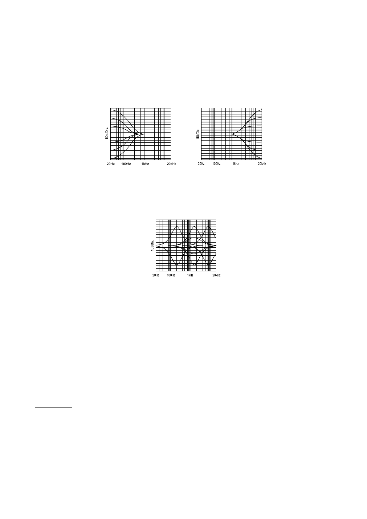
4.1.8 Optional 3 bands semi-parametric Equalizer [EQ]
Each of the input channels of the SX-ES64 can be equipped with an optional equalizer module. The design of
this powerful 3-band semi parametric equalizer is derived from previous models SONOSAX SX-S and SX-ST
whose effectiveness and sonic transparency has been proven on the field for decades.
• 80 Hz and 8 kHz: these filters have a shelve curve. Bass and treble adjustments are controlled by the
[80Hz ] and [8kHz] knobs within a range of ±15 dB
• MF: is a semi-parametric (sweep frequency) equalizer with a broad fixed bandwidth. ( Q Factor: -- )
The upper knob progressively adjusts the central frequency from 200 Hz to 8 kHz, the lower knob adjusts
the gain of the filter.
4.1.9 3 Leds peak-meter
This small peak-meter indicates the pre-fader level of the input channel. It also indicates an eventual overload
and the activity of the Limiter. The modulation is measured after the microphone preamplifier and after the
equalizer sections but before the fader of the channel. Thus it allows controlling the modulation level even if
the fader is closed.
The peak-meter works either in DOT mode or as a conventional Bargraph, depending on the Power On switch
position [ECO] or [ON].
Level indications: YELLOW: lights on as soon as the modulation reaches approx –20dB.
GREEN: lights on as soon as the modulation reaches the nominal level 0dB
RED: light on 10dB above nominal level
Input Limiters
: when the modulation reaches the threshold level of the limiter, both the Green and the
Red leds light on simultaneously.
Overloads
: The overload indication turns on 4 dB before the clipping is reached.
When in Bargraph mode, only the upper red led is lighting, all others turn off.
When in DOT mode, all leds light on simultaneously,
NOTE: the brightness of the leds varies automatically depending on the ambient light.
A light sensor is located under the secondary peak-meter
User manual SONOSAX SX-ES64 Page 10 of 27
Page 11

4.1.10 Pre-Fader Listening [PFL]
The [PFL] functionality - Pre-Fader Listening - is used to isolate and listen to the channel's modulation before
the fader. Thus, the settings of the channel such as the input gain, EQ and LF Cut can be adjusted precisely,
without being affected by listening to other channels. Multiple channels can be summed in PFL mode.
Once a PFL is activated, the modulation of the corresponding channel becomes audible in the headphone
outputs of the primary monitoring instead of the current selection, and its level is displayed on the secondary
modulometer instead of Masters 3 & 4. The PFL is signalled by the Yellow LED at the bottom left side of the
secondary modulometer.
When PFL is disabled, the monitor and the secondary modulometer return to their previous selection
NOTE: By default, the pre-listening is PRE-Fader (PFL), an internal solder jumper can change this
function to AFTER-Fader Listening (AFL) (please specify when ordering). AFL modulation is
taken before the PAN.
4.1.11 Channel fader
A high quality, plastic conductive, 100mm linear fader allows precise control of the signal level sent to the mix
busses 1 to 4 and also to the direct channel output if set to post-fader.
The fader has a logarithmic course with a scale graduated in decibels on both side on the cursor. The fader
range goes - infinite to +12 dB.
User manual SONOSAX SX-ES64 Page 11 of 27
Page 12

4.2 MIX BUS ASSIGNEMENT ROUTING SWITCHES [ 1 TO 4 ]
The SX-ES64 audio mixer is equipped with 4 mix buses, commonly called "Groups". The input channels are
assigned to mix busses using the advanced routing selector switches [1 to 4]. The 3 positions routing switches
allows to create either 4 Mono groups or 2 Stereo groups or free combinations of Mono and Stereo groups.
The routing selector can be configured in two different ways to suit each user's requirement. Thus, how to
assign the input channels on the mix bus can be configured in two distinct ways:
either: - Pre-Fader / Off / Post-Pan ( default setting )
or: - Post-Fader Pre-Pan / Off / Post-Pan ( the PAN is always post fader )
The configuration is determined by a soldering jumper on the input module circuit
This advanced bus assignment selector allows complex routing configurations. Each channel can be
individually assigned Pre-Fader or Post-Fader-Pre-Pan (depending on the chosen configuration) to a Mono
group used for example as an auxiliary bus, and simultaneously this channel can be assigned Post Pan to a
Stereo Group as main stereo mix.
The selector can then assign each input channel to the mixing buses 1 to 4, as follows:
Switches 1 to 4 in centre position: no audio is assigned to the corresponding mix bus
Switches 1 and/or 3 positioned on the left: assign the channel to odd busses Post PAN
Switches 1 and/or 3 positioned on the right: assign the channel to odd busses Pre-Fader
or Post-Fader-Pre-Pan depending on the configuration
Switches 2 and/or 4 positioned on the right: assign the channel to even busses Post PAN
Switches 2 and/or 4 positioned on the left: assign the channel to even busses Pre-Fader
or Post-Fader-Pre-Pan depending on the configuration
The two white lines drawn on either side of the selector give a clear view of the channel assignment: when the
switch is positioned towards the white line, the assignment is always Post-Pan (hence post fader).
A good tip is to remember that, conventionally, odd busses correspond to the left channel and even busses
correspond to the Right channel of a stereo group. Thus, by positioning odd switches to the left and even
switches to the right you are in any logical Post-PAN assignment to a stereo mix bus.
On the Master module, the four groups are assembled in pairs: 1-2 and 3-4 which allows to controls the output
level of a stereo group with a single master fader.
4.2.1 Pan Pot (Panoramic Potentiometer)
The retractable PAN Pot knob progressively balances the modulation from left to right when used in
conjunction with the Mix Busses Selector switches located above.
It has a central detent to quickly find the centre of balance.
User manual SONOSAX SX-ES64 Page 12 of 27
Page 13
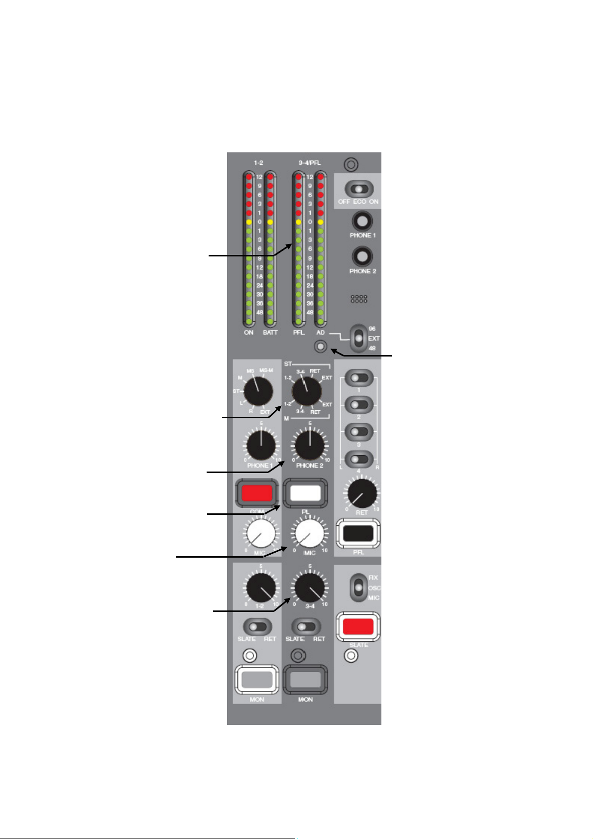
5. MASTER AND MONITORING SECTION
This section groups all functionalities related to the main outputs (Groups 1 to 4) such as the summing
amplifiers as well as the dual Monitoring and its communication system.
It also includes the 4 return channels (Return 1 to 4), the two stereo modulometer, the reference signal, the
integrated Com/Slate microphone and the control of the sampling frequency of the analogue / digital option.
Power ON switch
Primary monitor headphone
Main modulometer
Secondary modulometer Secondary monitor headphone
Electret microphone
ADC sampling frequency selector
Ambient Light sensor
Mode selector of Primary Monitoring
Source selector of secondary monitor Assignment of Return 1 to 4
to the Return mix bus
Primary Monitor volume
Secondary Monitor volume
Communication send Master fader of Return Mix
Private Line Communication
MIC 1 Level control Pre-Fader listening of Return mix
MIC 2 Level control
Master fader of Groups 1 & 2 Assign Slate Mic or Reference Tone
to the Slate bus
Master fader of Groups 3 & 4
SLATE or RET assignment SLATE Push button
to mix busses 1&2 / 3&4
Assign Group 1&2 and/or 3&4 to
the Primary Monitoring
User manual SONOSAX SX-ES64 Page 13 of 27
Page 14

5.1.1 Summing amplifiers [Master]
The summing amplifiers are mixing the modulation coming from input channels 1 to 6. The output level of the
Groups is controlled per pairs: 1-2 and 3-4. The two rotary stereo master faders are retractable and adjust the
output level from -infinity (mute) to 0dB (unity gain).
The nominal output level is set either at +6dBu or +4dBu (please specify when ordering). It corresponds to a
reading of "0 dB" on the modulometer. The peak meters are factory programmed and their ballistic can not be
changed by the user.
The sums of the 4 groups are then sent to the main outputs OUT 1 to OUT4. These four master outputs are
electronically balanced, transformer less.
The output connector for OUT 1 to OUT4 is an XLR-3 male where:
Pin1 = Gnd / Pin2 = High (+) / Pin3 = Low (-).
To connect the main output on an unbalanced receiver's input, pin 1 & 3 must be bridged and connected to
the Gnd of the receiver's input. The pin 2 is to be used as an unbalanced line output.
Master outputs 1 & 2 are also available on the Sub-D25 connector [Line Outs] and on the digital out AES # 4 if
the mixer is equipped with the optional A/D converter and, if fitted, on the optional connector [OPTION] on the
rear panel.
WARNING:
Meanwhile the outputs of the SX-ES64 are protected against DC voltages, we strongly
recommend not to connect a phantom power to the output of the mixer (for example when
connecting to a camera input, make sure that the phantom power of the camera is turned off).
5.1.2 Switches [ SLATE – Off – RET ]
The SX-ES64 has two extra buses, in addition to the main mix buses; a [SLATE] bus and a stereo bus coming
from the returns 1 to 4 [RET].
The three positions switches underneath the master faders assign and mix either the "Slate Bus" or the
"Return bus" to the pair of groups 1-2 and 3-4.
Left ← SLATE position: assign the Slate bus to the group's mix bus as soon as the [SLATE] push
Middle OFF position: No assignment to the mix bus.
button is depressed
Right → RET position: assign the stereo Return bus to the mix bus.
5.1.3 Group Monitoring [ MON ]
The [MON] push buttons underneath the master faders sends the modulation of the groups 1-2 and 3-4 to the
main monitoring.
The two keys can be used individually to listen separately to the groups 1-2 or 3-4 or simultaneously to
summon the 4 groups on the main monitor.
While in stereo mode, the odd groups 1 and 3 are heard on the left channel and groups 2 and 4 on the right
channel of the main monitoring. A selector in the main Monitoring section determines the listening mode (see
Main Monitoring Chapter).
User manual SONOSAX SX-ES64 Page 14 of 27
Page 15

5.2 SLATE MIC AND OSCILLATOR [ MIC OSC FIX ] AND [ SLATE ] KEY
The SX-ES64 mixer is equipped with a microphone for the Slate & Communication system as well as a 1kHz
reference tone located in the lower right corner of the front panel. A three-position switch [MIC OSC FIX]
selects which of these two sources will be sent to the main outputs 1-2 and 3-4 via the SLATE bus as follows:
Position MIC: temporarily send the signal of the integrated microphone to the SLATE bus when the
red push button [SLATE] is pressed.
Position OSC: temporarily send the signal of the 1kHz reference tone to the SLATE bus when the red
push button [SLATE] is pressed.
Position FIX: the 1kHz reference tone permanently feed the SLATE bus. The reference tone is
set at nominal line level . This Ref Tone is generally used for level calibration or
for test procedures.
NOTE: - the nominal level of the reference tone is either +6dBu or +4dBu depending on the setting at
the ordering. The peak meters indicate 0dB
- the Slate & communication microphone is located underneath the PHONE2 jack.
5.3 RETURNS 1 TO 4 [ RET ]
A 15 pin Sub-D located on the rear panel allows connection of 4 returns such as for a multi-track recorder or
any other external source at line level. They can be used for monitoring purposes and/or to assign and re-mix
the four returns to each pair of groups 1-2 and 3-4 through a stereo mix bus.
A row of four switches is used to individual assign and mix each of the four returns to the stereo "return bus".
Left position: assign the return to the left channel of the return mix bus
Middle OFF position: the return path is not assigned
Right position: assign the return to the right channel of the return mix bus
NOTE: The position [RET] of the switch located below the master faders 1-2 and 3-4 re-mix the return
bus into the busses of the relevant pair of groups.
5.3.1 Return Mix Master level
The rotary fader located under the return switches adjusts the mix level of the returns from - infinite to +10 dB.
5.3.2 Return's Pre-Fader Listening [ PFL ]
The [PFL] push button located at the bottom of the return section is used to listen to the returns on the main
monitor before the return's master fader. Once this button is pressed the stereo return bus becomes audible in
the headphone outputs instead of main monitor selection and the pre-fader level is displayed on the
secondary modulometer. This is indicated by the Yellow LED [PFL] on the secondary modulometer
NOTE 1: The pre-listening of the returns overrides the selection of monitoring [MON]. Once this button
is activated, it automatically cuts the main selection.
NOTE 2: By default, the pre-listening is Pre-Fader, an internal solder jumper can change this function to
After-Fader Listening (please specify when ordering)
User manual SONOSAX SX-ES64 Page 15 of 27
Page 16

5.4 MONITORING
The SX-ES64 audio mixer offers two independent stereo Monitoring sections and a so called Private Line
communication system.
5.4.1 Main Monitor source selector [ MON ]
The left most Monitor section (the Main Monitor) is dedicated to the sound engineer working on the mixer. It
allows the monitoring of the Master groups 1 to 4, to pre-listen to the input channels and the four returns as
well as a confidence return [EXT] if the optional connector is fitted.
The main monitor sources are the master groups 1-2 and 3-4. The selection is done with the [MON] push
buttons located under the master faders. While in stereo mode, the groups 1 and 3 are heard on the left
channel and groups 2 and 4 on the right channel of the main monitoring.
As soon as any [PFL] key is pressed, the PFL will automatically override the main monitoring selection and the
Yellow Led [PFL] on the secondary modulometer will turn on.
This main monitoring has two headphone outputs connected in parallel: the [PHONE1] output on a stereo jack
6.25 mm (1/4 ") located on the back panel and the [PHONE1] output on a mini-jack 3,5mm (1 / 8 ") located on
the front panel.
5.4.2 Monitor Mode selector [ EXT L R ST M MS MS/M]
The rotary switch defines the operating mode of the main monitor. Thus the selected source can be monitored
in the following ways
MS/M: the audio is MS decoded and then summed in Mono.
MS: decode an MS source for monitoring purposes only.
M: the selected stereo source is summed to mono. This is useful to easily check the mono
compatibility and detect a potential phase problem.
ST: the selected stereo source is monitored in stereo.
L: the left channel is monitored in mono on the both channels of the headphones.
R: the right channel is monitored in mono on the both channels of the headphones.
EXT: confidence monitoring of an additional stereo return if wired on the optional connector.
NOTE 1: The MS decoder only affects the monitoring, not the main outputs. The decoder ration is fixed
to 50%. The M channel is sent in phase to both the left and right ears and the S channel is
sent in phase to the left ear and in reversed phase to the right ear.
NOTE 2: The [EXT] is only audible if the optional connector [OPTION[ is installed. (see the optional
connectors in the addendum chapter for the available connectors and their wiring).
5.4.3 Headphone level [ PHONE1 ]
This retractable potentiometer adjusts the level of the main monitor outputs between –infinite to +15dBu. As
both PHONE1 connectors are wired in parallel, the volume controls both outputs.
WARNING: The headphone amplifier of the SONOSAX SX-ES64 is quite powerful. It is highly
recommended to set the headphone level at a reasonable level to protect our precious ears.
5.4.4 Command switch [ COM ]
This push button allows sending announces on the secondary monitor output, but does not to the main
outputs. It is also heard as "Side Tone" in the main monitoring. There is no returned communication in this
mode.
5.4.5 Potentiometer [ MIC1 ]
The retractable knob [MIC1] adjusts the level of integrated electrets microphone. This microphone is used for
the SLATE, for the COM and for the private line PL1. The microphone is located under the PHONE2 jack.
User manual SONOSAX SX-ES64 Page 16 of 27
Page 17

5.4.6 Secondary Monitor selector [ 1-2 3-4 RET EXT - ]
The section of the secondary monitor is used generally for remote monitoring; it is totally separate from the
main monitoring. This section is typically used as an alternate monitor for a video control room or a speaker
cabin in a broadcast application, or for the boom operator and/or the director while a recording on location. It
provides with an off-line full duplex communication system (Private Line).
The output of the secondary monitor is available simultaneously on the XLR-6M [COM / PL] on the rear panel
and on the [PHONE2] mini-jack output on the front panel. Both outputs are internally wired in parallel.
The monitor selector let choose from four different sources to be listened in mono if the selector is in the lower
section "M" or in stereo if the selector is in the upper section "ST". The monitoring is muted in the intermediate
position.
1-2: monitors masters 1 and 2, either in mono or in stereo
3-4: monitors masters 3 and 4, either in mono or in stereo
RET: monitors the return mix bus after the fader (AFL).
EXT: confidence monitoring of an additional stereo return if wired on the optional connector
NOTE: The [EXT] is only audible if the optional connector [OPTION[ is installed. (see the chapter
optional connectors and the addendum for the available connectors and their wiring).
5.4.7 Headphone level [ PHONE2 ]
This retractable potentiometer adjusts the level of the secondary monitor outputs between –infinite to +15dBu.
As both PHONE2 connectors are wired in parallel, the volume controls both outputs.
WARNING: The headphone amplifier of the SONOSAX SX-ES64 is quite powerful. It is highly
recommended to set the headphone level at a reasonable level to protect our precious ears.
5.4.8 Touche [ PL1 ]
This push button activates the communication in full duplex mode over the private line PL1.
The communication's send is using the integrated microphone and is controlled by the potentiometer [MIC1].
For duplex communication, an external microphone must be connected for the returned communication to the
XLR-6M [COM / PL] connector. Its volume is controlled by potentiometer [MIC2]. Note that this connection is
permanently powered with a 48V phantom voltage.
PL1 communication can be remotely activated by bridging via a switch the ground (Gnd) of the external
microphone line and the ground of the secondary monitor connector XLR6-M [COM / PL]
A small boom box with bet clip is available under reference SX 022260.
5.4.9 Potentiomètre [ MIC2 ]
The retractable potentiometer [MIC2] controls the volume of the external microphone being used for the full
duplex communication over the private line PL1. It must be connected to the XLR-6M [COM/PL].
WARNING: The microphone input for the return communication on the connector XLR6-M [COM / PL] is
permanently powered with 48V Phantom voltage.
5.4.10 Headphone outputs [ PHONE1 et PHONE 2 ]
These mini-jack 3,5mm ( 1/8" ) headphone outputs allow any kind of stereo or mono headphone having an
impedance between 35 and 400 ohms.
The [PHONE1] output is wired in parallel with the main monitoring output on the jack 6,35 ( 1/4" ). The
[PHONE2] is wired in parallel with the secondary monitor output on the XLR6-M. Thus, it is possible to
connect two headphones on each of the two monitoring outputs.
Headphone outs are mini-jack stereo 3,5mm ( 1/8" ) where:
Sleeve = Gnd / Ring = Right channel / Tip = Left channel
WARNING: The headphone amplifier of the SONOSAX SX-ES64 is quite powerful. It is highly
recommended to set the headphone level at a reasonable level to protect our precious ears.
User manual SONOSAX SX-ES64 Page 17 of 27
Page 18

5.5 LEDS PEAK-METERS [ PEAK-METERS ]
Two dual LED peak-meters display the modulation levels over a large scale from -48dB to +12 dB. The
modulation is displayed either in Dot mode or as conventional Bargraph according to the power on mode
[ECO] or [ON].
The modulometers are factory programmed to behave as peak-meter. The 0dB reference corresponds to the
nominal output level that is either of +6 dBu or +4 dBu.
The main stereo modulometer on the left [1-2] always displays the modulation of Masters 1 & 2. The yellow
[ON] Led at the bottom of the left channel confirms that the unit is powered on. The red [BATT] Led at the
bottom of the right channel indicates that the unit is powered from its internal batteries. This Led is flashing
with a period that depends on the remaining battery charge (see chapter 1.1).
The secondary stereo modulometer on the right [ 3-4/PFL ] shows either the modulation of the Master 3 & 4 or
the modulation level of the returns 1 to 4 or the pre-fader modulation of an input channel as soon as a PFL
button is engaged. When all PFL button are released, then the peak-meters turns back to show the level of
Master 3 & 4.
The yellow Led [PFL] at the bottom of the left channel indicates that a least one PFL is switched. The red Led
[AD] at the bottom of the right channel warns for an eventual clipping of the A/D Converter or if the external
wordclock frequency is out of range.
The brightness of the Leds is varies automatically according to the ambient light. A light sensor is located just
below the [AD] led.
User manual SONOSAX SX-ES64 Page 18 of 27
Page 19

6. DIGITAL OUTPUT [ AES ]
A high quality Analogue to Digital converter is available as an option. It performs the digital conversion of 8
audio channels with a resolution of 24 bits. These 8-channel audio are grouped in pairs; four AES-31,
transformers balanced digital outputs are available on the Sub-D 25 pin connector [DIGITAL OUT] on the rear
panel. Any external devices providing with AES digital input can be connected such as digital cameras,
external audio recorder or a computer via a digital audio interface, etc.
By default these 8 channels are internally wired to the direct outputs of the six input channels and to the main
out of groups 1 & 2. On request, the main out of groups 3 & 4 can be wired instead of channels 5 & 6.
The direct out of the channels are taken either Pre-Eq, or Post-Eq or Post-fader. Selection is made by an
internal soldering jumper on the input module.
The four AES outputs are configured as follows:
• AES#1 : direct outputs of channels 1 & 2
• AES#2 : direct outputs of channels 3 & 4
• AES#3 : direct outputs of channels 5 & 6 ( or Master 3 & 4 )
• AES#4 : Master outputs 1 & 2
The digital audio level is set at factory and depends on the nominal output level, this means of the analogue
output level corresponding to a reading of "0 Peak" on the modulometre
- the digital level is -18dBFS if the SX-ES64 is set for a nominal output of +6dBu when reading "0 Peak"
- the digital level is -20dBFS if the SX-ES64 is set for a nominal output of +4dBu when reading "0 Peak"
NOTE:
The selection of the direct output source for the ADC is independent from the one that feed
the analogue direct channel output.
6.1.1 Sampling frequencies [ 96 EXT 48 ]
By default the SX-ES64 internal clock provides with two sampling frequencies; either 48kHz or 96kHz
selectable with the switch [96 EXT 48].
While in [EXT] position, the A/D Converter will automatically lock on any external wordclock connected to
"WCKL IN" connector and having a frequency between 22kHz to 200kHz.
If the switch is set to [EXT] and no external word clock signal is detected, the A/D converter is then turned off,
which saves on batteries if the converter is not used.
The WCKL OUT connector provides with a re-clocked wordclock signal at the same sampling frequency as
the A/D Converter.
NOTE: - by default, the ADC offers the choice of 48kHz and 96kHz at 24bits and outputs an AES-31
signal. Internal jumpers offer following choices:
- FS at 192kHz/24bits instead of 48kHz (the position 96kHz remain unchanged)
- 48kHz at 16 bits instead of 24bits ( the 96kHz position remain unchanged at 24 bits)
WARNING: Any modification of the default settings must be done by a qualified technician.
Please contact SONOSAX our your nearest Sonosax dealer
User manual SONOSAX SX-ES64 Page 19 of 27
Page 20
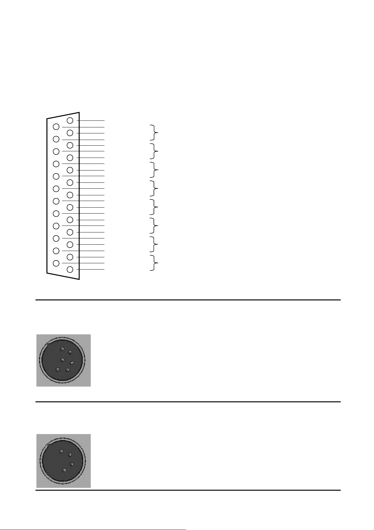
7. ADDENDUM
7.1.1 Main connectors wiring diagrams
LINE OUT
25 pin Sub-D female Mating cable connector: 25 pin Sub-D male
13 => n.c.
25 => ground
12 => Low - Direct Out Channel 1
24 => High +
11 => ground
23 => Low - Direct Out Channel 2
10 => High +
22 => ground
9 => Low - Direct Out Channel 3
21 => High +
8 => ground
20 => Low - Direct Out Channel 4
7 => High +
19 => ground
6 => Low - Direct Out Channel 5
18 => High +
5 => ground
17 => Low - Direct Out Channel 6
4 => High +
16 => ground
3 => Low - Main Out 1 (internally wired in parallel with XLR OUT 1)
15 => High +
2 => ground
14=> Low - Main Out 2 (internally wired in parallel with XLR OUT 2)
1 => High +
MON2/PL
XLR-6M Compatible with SONOSAX BOOM BOX
Mating cable connector: XLR-6F
EXT DC IN 6 to 18 Volts
XLR-4M Mating cable connector: XLR-4F
Pin 1 = Monitor 2 Out LEFT
Pin 2 = Monitor 2 Out RIGHT
Pin 3 = Monitor 2 Gnd
Pin 4 = PL microphone Hi +
Pin 5 = PL microphone Lo Pin 6 = PL microphone Gnd & CALL
Bridge Pin 6 ( Gnd/CALL ) and pin 3 (Gnd ) via a switch to activate the PL1 CALL function
Pin 1 = GND
Pin 2 = n.c
Pin 3 = n.c
Pin 4 = Positive DC Voltage 6 to 18 Volts
User manual SONOSAX SX-ES64 Page 20 of 27
Page 21
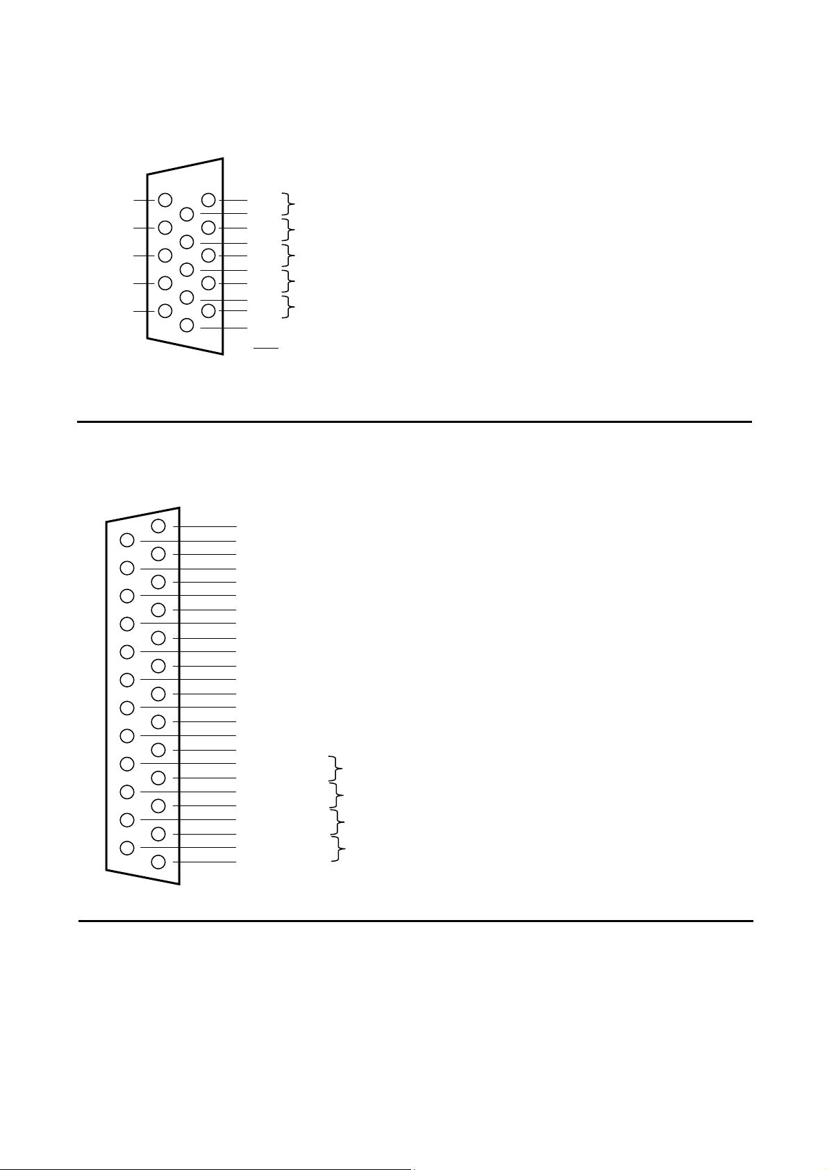
RETURN 1 to 4 / VU Out
6
0 5
5
Condensed 15 pin Sub-D female Mating cable connector: condensed 15 pin Sub-D male
Hi + Low -
Gnd
1
RET 1: Hi Low
Gnd
RET 2: Hi Low
Gnd
RET 3: Hi Low
Gnd
RET 4: Hi Low
Gnd
VU Left Right
Gnd
11
Note: VU-Meter output is unbalanced. Reading "0" = 0dBu
1
RET 1
RET 2
RET 3
RET 4
1
VU- Meter Out
DIGITAL AES/EBU Outputs ( option )
25 pin Sub-D female Mating cable connector: 25 pin Sub-D male
19 => ground AES 4
6 => ground AES 3
18 => ground AES 2
5 => ground AES 1
17 => Low - AES/EBU 4 (Main outputs 1&2 )
4 => High +
16 => Low - AES/EBU 3 (Direct out of channels 5 & 6 or Main output 3&4)
3 => High +
15 => Low - AES/EBU 2 (Direct out of channels 3 & 4 )
2 => High +
14=> Low - AES/EBU 1 (Direct out of channels 1 & 2 )
1 => High +
User manual SONOSAX SX-ES64 Page 21 of 27
Page 22
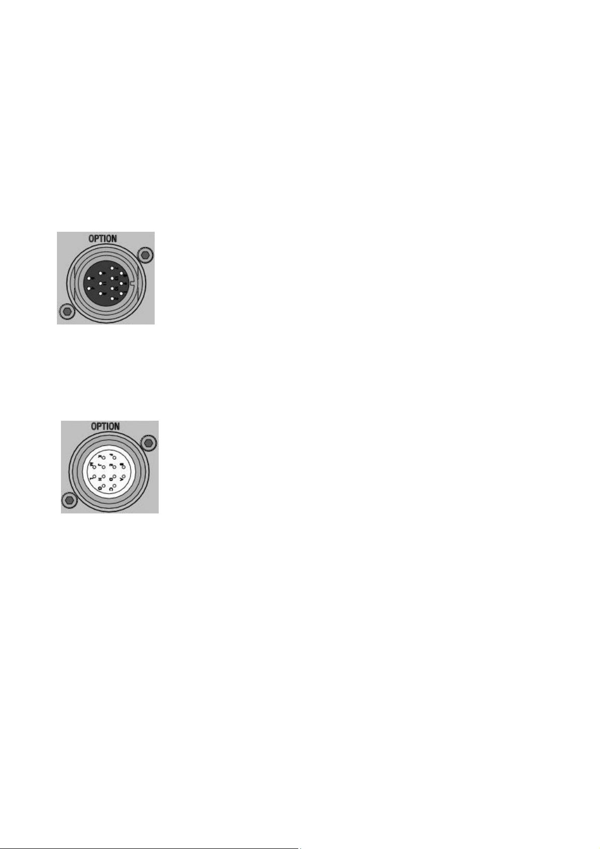
7.1.2 Optional connectors [OPTION]
An optional connector can be installed for direct connection to a camera with a confidence return monitoring
for example. By default, these connectors provide with the Main outputs 1 &2 and the confidence return
monitor is internally wired to the [EXT] position of the monitoring selectors (see chapter 5.4)
A choice of connectors is available such as Tajimi 12 pin or Hirose 10 pin.
The wiring of these connectors is compatible with existing cables that the user may already have purchased
with mixers of other brand. Other type of connectors are available on request.
HIROSE 10 PIN Compatible with: Audio Development / SQN / SOUND DEVICES / COOPER / MIXY
RM15TRD-10S Mating cable connector: RM15TPD-10P
TAJIMI 12 PIN Compatible with: SQN / Mixy / Sony
PRC 05R 12F Mating cable connector: PRC05P12M
1 => MAIN Out 1 Hi +
2 => MAIN Out 1 Lo 3 => MAIN Out 2 Hi +
4 => MAIN Out 2 Lo 5 => Return RIGHT Hi+ ( connected to EXT on Monitor selector )
6 => Return RIGHT Lo - or Gnd if unballanced
7 => Return LEFT Hi+ ( connected to EXT on Monitor selector )
8 => Return LEFT Lo - or Gnd if unbalanced
9 => GND
10 => GND
A => MAIN Out 1 Hi +
B => MAIN Out 1 Lo C => MAIN Out 2 Hi +
D => MAIN Out 2 Lo E => Return LEFT Hi+ ( connected to EXT on Monitor selector )
F => Return LEFT Lo - or Gnd if unballanced
G => Return RIGHT Hi+ ( connected to EXT on Monitor selector )
H => Return RIGHT Lo - or Gnd if unballanced
J => GND
K => GND
L => n.c.
M => n.c.
User manual SONOSAX SX-ES64 Page 22 of 27
Page 23
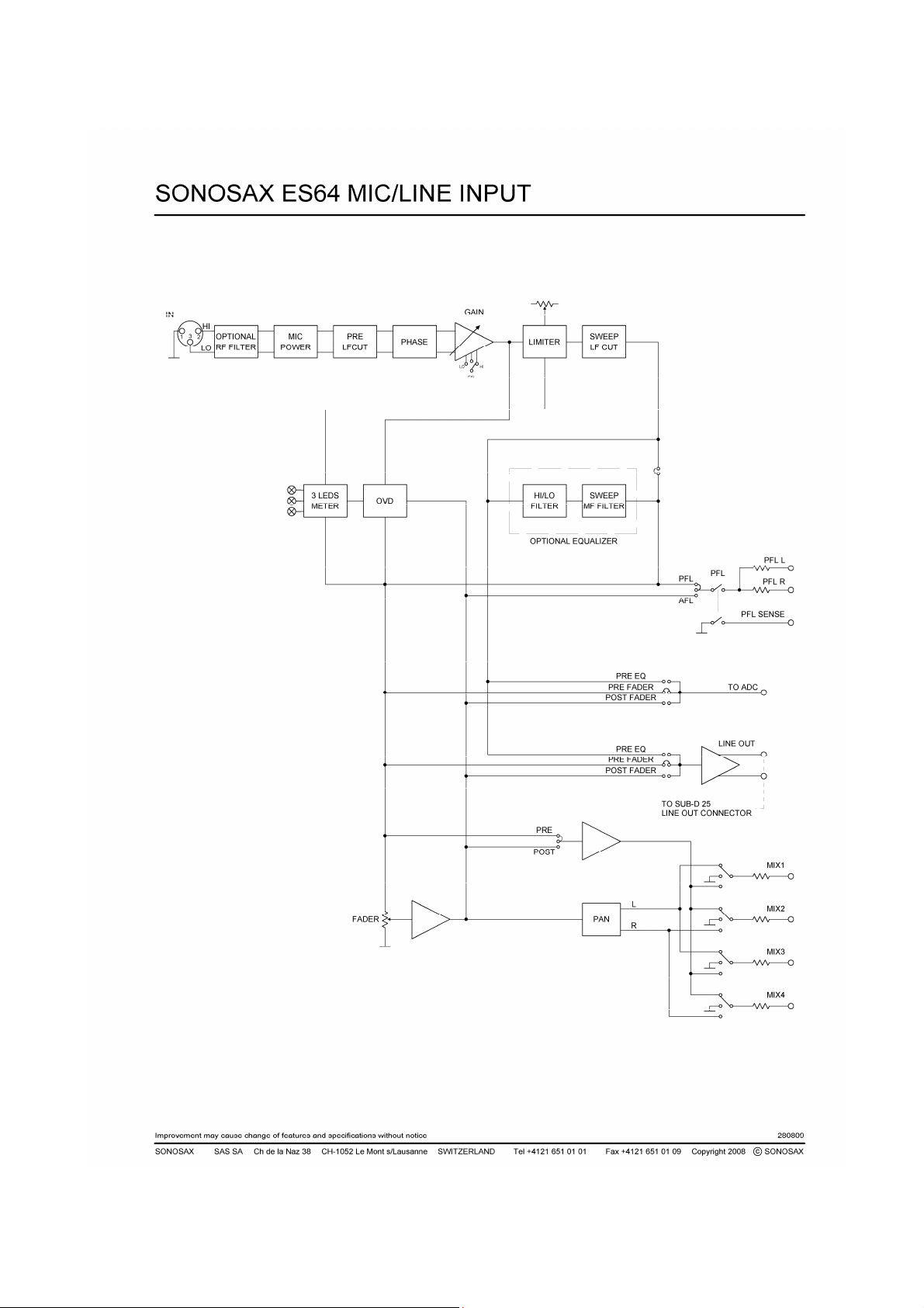
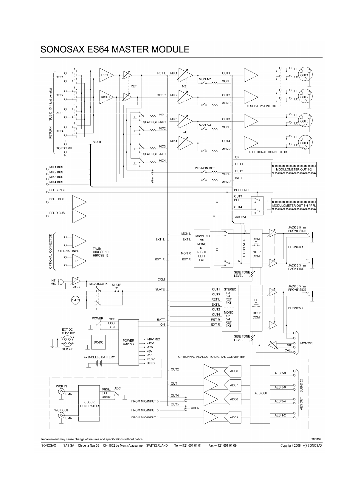
7.2 BLOC DIAGRAMM
User manual SONOSAX SX-ES64 Page 23 of 27
Page 24
User manual SONOSAX SX-ES64 Page 24 of 27
Page 25

8. SPECIFICATIONS
All specifications mentioned below are given for standard models. SONOSAX SAS SA reserves the right to
change these data at any time without notice
For measurements and/or adjustment, the reference is: 0dBu = 0.775V (+6dBu = 1.55V, +4dBu = 1,23V)
Summary of characteristics
Overall Bandwidth: +/-1dB 30Hz to over 200kHz (-3db @ 25Hz / -3dB @ 300kHz)
Maximal Gain: 92dB
Overall Dynamique range: input / output at 0dB of gain => 113dB
Crosstalk: lower than -120dB between channels
Modulometer: Peak IEC-268-10 type 1
Working temperature : -25°C [-13°F] to 70°C [158°F]
GAIN 92dB 76dB 56dB 36dB 16dB 0dB
Nominal level: -86dBu -70dBu -50dBu -30dBu -10dBu +6dBu
Maximum level: -68dBu -51dBu -24dBu -4dBu +8.5dBu +21dBu
THD+N 0.3% 0.05% 0.02% 0.01% 0.01% 0.01%
CMRR** >80dB >80dB >80dB >80dB >70dB >60dB
Noise LIN** -128.0dBu -128dBu -128.0dBu -124dBu -102.7dBu -93dBu
* 22 Hz to 22 kHz, at maximum input level
** Equivalent input noise from a 150Ω source
Output noise:
No channel assigned:
Master Fader at 0dB: -94dBu => s/n 100dB *
Master Fader closed: -96dBu => s/n 102dB *
6 channels assigned, master fader at "0":
Channel fader closed: -84.5dBu => s/n 90.5dB *
Channel fader at 0 : -80.8dBu => s/n 86.8dB *
* s/n = signal to noise ratio at nominal output level, with 18dB respectively 20dB of headroom
INPUTS
MIC/LINE INPUT
Input type: electronically balanced, transformer-less
Input Impedance: 6.8kΩ linear from 22 Hz to 22 kHz, 4kΩ with pre- LF Cut,
RF Filters: optional
Pre-LF Cut: passive filter, 135Hz 6dB/octave
Sweep LF Cut: active filter, adjustable from 25 to 350Hz, 12dB/octave
Microphone powering: +48V [phantom power]
RETURN INPUT
Input type: electronically balanced, transformer-less
Sensibility: adjustable from – 6dBu to +25dBu
Return impedance: 18kΩ
User manual SONOSAX SX-ES64 Page 25 of 27
Page 26

OUTPUTS
MAIN OUTPUTS
Output type: electronically balanced, transformer-less
Output impedance: <50Ω
Nominal output level: +6dBu or +4 dBu (as specified at the order)
Maximal output level: +24dBu @600Ω
DIGITAL OUTPUT
Output type: AES/EBU transformer balanced, 3.0Volts pp,
Sampling frequencies: 48kHz and 96Khz at 24 bits
internally adjustable to 48Khz/16 bits and 96kHz/24bits
or 96kHz/24bits et 48Hz/24bits
Digital audio level: -18dBFS at 0 Peak if the nominal level is set at +6dBu
-20dBFS at 0 Peak if the nominal level is set at +4dBu
Dynamic range: linear: 110 dB / asa A: 114dB
HEADPHONE/MONITOR OUTPUT
Output type: stereo unbalanced, on Jack 6,25mm (1/4") and 3,5mm (1/8")
Nominal output level: adjustable from –infinite to +15dBu
Minimum load: 30Ω
REF OSCILLATOR:
Frequency: 1kHz
THD: < 3%
POWER SUPPLY
Batteries: four rechargeable NiMh or NiCd LR20 (D cells) or alkaline disposable
External power: 6V to 18V DC, minimum 20Watts
Average power consumption: aprox. 11Watts without Phantom power
Running time: aprox 4 hours with four rechargeable NiMh 10Ah LR20 (D cells)
aprox 2.5 hours four disposable alkaline LR20 (D cells)
WEIGHT AND SIZE
Dimensions [W*D*H]: 277 x 292 x 66 mm / 10.9" x 11.5" x 2.6"
Weight without batteries: 3,55 kg (7.82 lbs)
Weight without batteries: aprox 4,2 kg [9,2 lbs] with four rechargeable NiMh LR20 (D cells)
User manual SONOSAX SX-ES64 Page 26 of 27
Page 27

9. TIPS ON USING YOUR MIXER
The SONOSAX SX-ES64 has been designed to offer outstanding performances. However, bear in mind that a
good sound recording greatly depends on microphone placement and on dynamics.
We therefore recommend the following:
• Adjust the input gain level at maximum possible level, reading between 0 dB and +6 dB on the main
meters, but keep a reasonable headroom.
• Input faders should act between 0dB and +10dB.
• Preferably try to operate at highest possible levels at the first amplification stage or at microphone pre-
amp levels.
• Make sure that interconnections between your SX-ES64 mixer and other equipments are correct and
optimal.
• Optimize operating conditions (location, quality of microphones, etc.)
Considering the extensive possibilities offered by your SONOSAX SX-ES64 mixer, this instruction manual
may not answer all questions that may arise during normal operation of your equipment. Please contact your
nearest SONOSAX dealer for any further information.
The information contained in this manual is subject to change without notice.
All specifications mentioned in this manual apply to standard models only.
SONOSAX SAS SA reserves the right to modify these characteristics at any time without prior notice.
No part of this manual may be reproduced or transmitted in any form or by any means, electronic or
mechanical including photocopying and recording of any kind, for any purpose, without the express
written permission of SONOSAX SAS SA.
© 2003 SONOSAX SAS SA, Ch. de la Naz 38, 1052 Le Mont s/Lausanne, Switzerland.
Phone: +41 21 651 0101, Fax: +41 21 651 0109, Email: [email protected] Web: www.sonosax.ch
User manual SONOSAX SX-ES64 Page 27 of 27
 Loading...