

SONOSAX SX-62R User Manual

PROFESSIONNAL
MIXER / RECORDER
SONOSAX
SX62R
Quick Start Guide
(Firmware revision 4.1)
audio equipment manufacturer
SONOSAX SAS S.A.
Ch. de la Naz 38
1052 Le Mont s/Lausanne
SUISSE
Tel: +41 21 651 0101
Fax: +41 21 651 0109
Web: www.sonosax.ch
Email: sonosax@sonosax.ch
August 2011

TABLE OF CONTENT
1. POWERING THE SX62R ..................................................................................................................................... 3
1.1 SWITCHING ON................................................................................................................................................... 3
2. MAIN DISPLAYS ................................................................................................................................................. 4
2.1 INPUT CHANNELS VS RECORDER TRACKS...................................................................................................4
2.2 INPUTS MODULOMETERS................................................................................................................................. 4
2.3 TRACKS MODULOMETERS............................................................................................................................... 5
2.4 RECORDER STATUS.......................................................................................................................................... 6
2.4.1 Toggle Switch ....................................................................................................................................................... 6
3. MAIN MENU......................................................................................................................................................... 7
4. ANALOGUE MIXER SECTION............................................................................................................................ 7
4.1 MIC/LINE INPUT .................................................................................................................................................. 7
4.2 MIC/LINE INPUT CONFIGURATIONS ................................................................................................................ 8
4.2.1 Input Controls ....................................................................................................................................................... 9
4.2.2 Limiter Threshold.................................................................................................................................................. 9
4.2.3 Input Assignment – Linking and Routing ............................................................................................................ 10
4.3 MASTER & MONITORING SECTION................................................................................................................ 11
4.4 OUTPUTS CONFIGURATIONS.........................................................................................................................12
4.4.1 MIX Output configuration.................................................................................................................................... 12
4.4.2 BOOM Output configuration ............................................................................................................................... 13
4.4.3 AUX Output configuration ................................................................................................................................... 14
4.4.4 Reference Tone Generator................................................................................................................................. 15
5. RECORDER SECTION ...................................................................................................................................... 16
5.1 HEADPHONES MONITORING CONFIGURATION...........................................................................................16
5.1.1 SOLO MONITORING MODE.............................................................................................................................. 16
5.2 TAG LAST TAKE...............................................................................................................................................17
5.3 METADATA .......................................................................................................................................................18
5.3.1 PLAYER mode: .................................................................................................................................................. 19
5.4 BROWSE FILES MENUS ..................................................................................................................................20
5.5 LAST TAKES MENU ......................................................................................................................................... 21
5.6 PLAYER MODE ................................................................................................................................................. 21
6. SETUP MENU .................................................................................................................................................... 22
6.1 CONFIGURING THE RECORDER .................................................................................................................... 22
6.1.1 Configuring the Tracks [REC TRACKS].............................................................................................................. 22
6.1.2 Track Routing ..................................................................................................................................................... 23
6.1.3 Track Naming ..................................................................................................................................................... 24
6.1.4 Example of a complete configuration.................................................................................................................. 24
6.1.5 Mirroring ............................................................................................................................................................. 24
6.1.6 Recording parameters [REC SETUP]................................................................................................................. 25
6.2 TIMECODE SETUP............................................................................................................................................ 26
6.3 USER SETTINGS............................................................................................................................................... 27
6.4 SYSTEM SETUP................................................................................................................................................28
6.5 TURNING OFF THE UNIT [POWER OFF] ........................................................................................................ 30
7. ADDENDUM....................................................................................................................................................... 31
7.1 REAR PANEL CONNECTORS..........................................................................................................................31
7.2 RIGHT SIDE PANEL CONNECTORS ............................................................................................................... 32
SONOSAX SX62R Quick Start Guide Page 2 of 34
1. POWERING THE SX62R
The SONOSAX SX62R can be powered either by:
- 4x internal rechargeable batteries ( 4x D Cells ); depending on the configuration and settings the running
time will be approx 4 to 5 hours with 10'000mAh NiMh cells.
- any regulated DC power supply from 6 to 18Volts, connected on the Hirose4: Pin 1 = Gnd / Pin 4 = +VDC
WARNING:
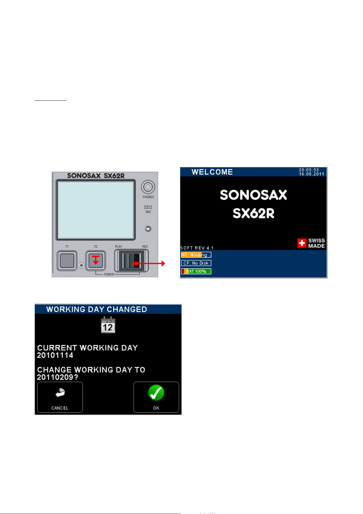
1.1 SWITCHING ON
Press [F2] and simultaneously push the toggle switch to [REC] to power on the SX62R. A boot up screen
appears as illustrated below.
Using dry cells such as alkaline batteries can lead to unexpected powering off or malfunctions
of the unit; use them with caution and only when no NiMh batteries are available;
replace alkaline batteries after 2 hours of use.
If the working day has changed while powering
up the unit, the system asks to confirm the date
of the new working day. This allows keeping the
date of the current working days if the on going
production works is passing across midnight.
Press [OK] to confirm the new working day
Press [CANCEL] to keep the current working day
When one of the key is pressed, the unit will
continue the booting procedure; wait a few
seconds until the main screen appears
SONOSAX SX62R Quick Start Guide Page 3 of 34
2. MAIN DISPLAYS
2.1 INPUT CHANNELS VS RECORDER TRACKS
When the booting procedure is completed, the main screen displays the modulometers of the inputs channels
as well as main information's related to the set up of the mixer and most of the recording parameters.
The main screen displays either the modulometers of the Inputs channels or the modulometers of the
recorder's tracks (see examples below). Touching the blue region at the bottom of the screen toggles the
metering of the Inputs channels or the metering of the recorder's Tracks.
For sake of clarity in reading this manual, please note that:
- Inputs or channels: always refer to a physical input or output of the analogue mixer
- Tracks: always refer to a virtual track of the recorder
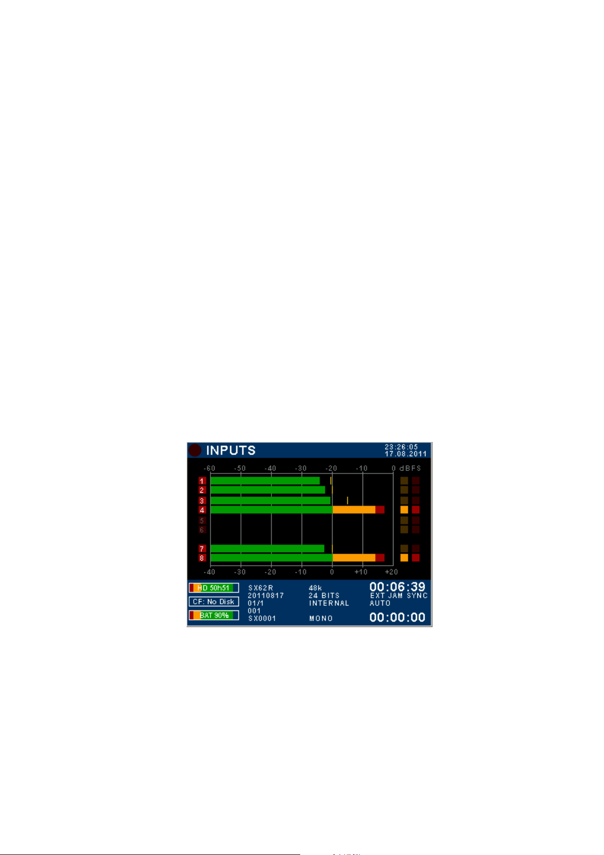
2.2 INPUTS MODULOMETERS
When the screen shows the INPUTS modulometers, numbers 1 to 6 represent the input channels of the mixer,
and 7 & 8 represent either the master Mix-L (7) and Mix-R (8) or the stereo [RETURN] inputs.
The first column - numbering from 1 to 8 - indicates the status of the input channels and of the master mix (or
the Return's inputs); the red square indicates the status of assigned and armed tracks.
- Number 1 to 6 represents the number of the input channels.
- A high-lighted number means that the input channel is powered [ON]; a dimmed number means that the
input channel is powered [OFF] (saving on batteries).
- Numbers 7 & 8 appearing over a Red square means that Stereo Master Outputs [Mix-L & Mix-R] are
assigned; either high-lighted (powered ON) or dimmed (powered OFF to save on batteries).
- Numbers 7 & 8 appearing over a Blue square means that the stereo [RETURN] inputs are assigned as
channels 7 & 8 instead of the master outputs.
- High-lighted Red square indicates that the recorder's track is assigned and armed, ready to record; dimmed
Red square means that no input is assigned and/or the track is not armed.
Input channels modulometers System Date & Time
Digital scale DBFS
1 to 4 brightened = input
channels are powered ON
High lighted Red squares = the
input are routed on armed tracks
5 & 6 are dimmed = input
channels are powered OFF
7 & 8 = Mix busses L & R
7 & 8 brightened = output
channels are powered ON
Analogue scale PPM 0 PPM = nominal output level
Remaining capacity on HD Time Code value
Remaining capacity on CF Time Code Synchronisation
Battery or external level indicator
(in volts)
SX62R =
20110817=
01/1 =
001 =
SX0001 =
Project name
Working Day
Scene name
Take number
Filetag
Sampling Frequency
Resolution (Bits per sample)
Audio Sync mode
Audio File format
Yellow Dot indicates Limiter
activity. Thresholds is set in
the Input menu
Red Dot = Overload
Elapsed time
SONOSAX SX62R Quick Start Guide Page 4 of 34
Another example of configuration
Inputs modulometers
1 to 6 are brightened = input channels are powered ON
Red square dots dimmed = input channels are not
routed (will not be recorded)
Faders of input channels 5 & 6 are linked
Red square: 7 & 8 = mix bus
Red square high-lighted = channels 7 & 8 routed on
armed tracks (will be recorded)
TOUCH THE LOWER REGION TO TOGGLE THE
METERING OF RECORDER'S TRACKS
7 & 8 brightened = L&R mix outputs powered ON
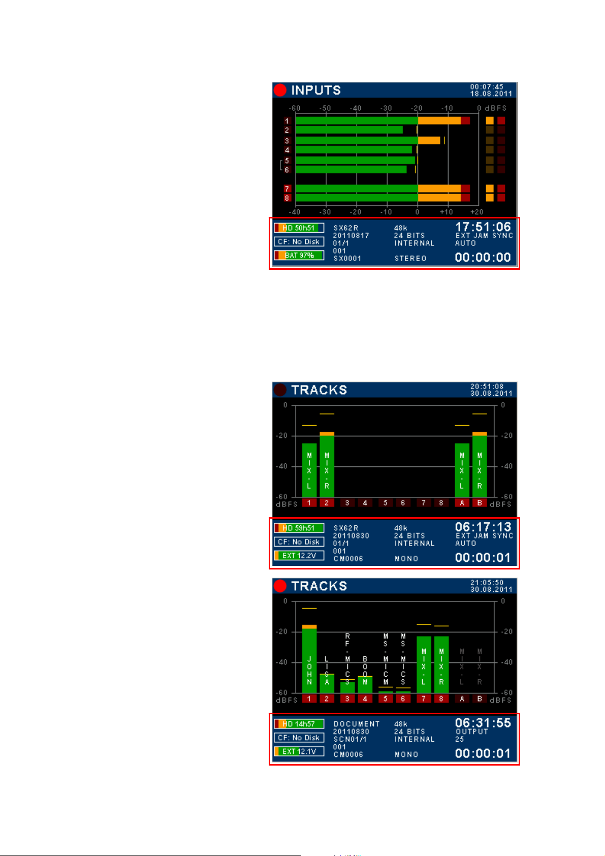
2.3 TRACKS MODULOMETERS
Multiple inputs can be routed (mixed) on the same track; thus when the screen displays the modulometers of
the recorder's TRACKS, each track represents the sum of all assigned inputs on that particular track, in other
words it shows what is effectively recorded on the tracks.
If the Input channels and the Master are not assigned in a 1:1 routing, toggling the metering allows a rapid
comparison between the modulation level of the channels and the modulation level of the recorded tracks.
Recorder's track modulometers
Master Mix-L & Mix-R are recorded on tracks 1 & 2 on
the H.D. and on tracks A & B on the CF Card
TOUCH THE LOWER REGION TO TOGGLE THE
METERING OF INPUT CHANNELS
Recorder track modulometers
Typical 1:1 assignment of input channels onto recorder's
track. In this example, tracks A & B of the CF Card are
not assigned and not armed
TOUCH THE LOWER REGION TO DISPLAY THE
METERING OF THE INPUT CHANNELS
SONOSAX SX62R Quick Start Guide Page 5 of 34
2.4 RECORDER STATUS
The status of the recorder is always posted on the upper left corner of the screen, regardless of the displayed
menu:
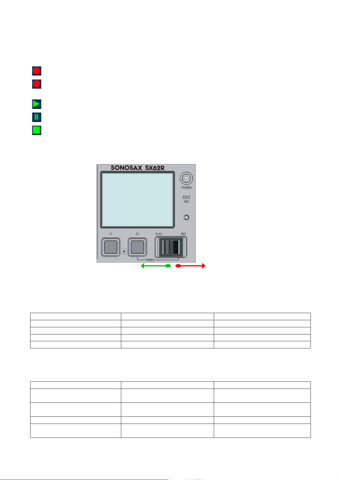
Red dot Flashing: Record Ready
Red dot Steady: Recording in progress, the lower region of the screen toggles from blue to red
Green triangle Steady: Playing a take
Green double bars: Player in Pause
and a second red dot is posted on the upper area of the screen
Green square flashing: Player in Stop
2.4.1 Toggle Switch
PLAY REC
Play-Pause-Stop Start/Stop Recording / Add an Index
The toggle switch controls the main functions of the recorder according to its operating mode:
RECORDER operating mode
Toggle switch Short pressure Long pressure
RIGHT in any situation Start recording
RIGHT while recording Add an INDEX ** Stop recording
LEFT while in record ready Call the last take and start playing
LEFT while playing Pauses at current position Stop playing
** INDEX = New TAKE: pressing the toggle switch briefly to the right while recording will automatically create
a new TAKE and the Take number is automatically incremented by 1.
PLAYER operating mode
Toggle switch Short pressure Long pressure
LEFT while in Stop Play the selected Take from the
beginning of the Take
LEFT while in Pause Play the selected Take from the
current position
LEFT while Playing PAUSES at current position STOP playing
RIGHT Switches to Record mode and start
recording (scratch record)
SONOSAX SX62R Quick Start Guide Page 6 of 34
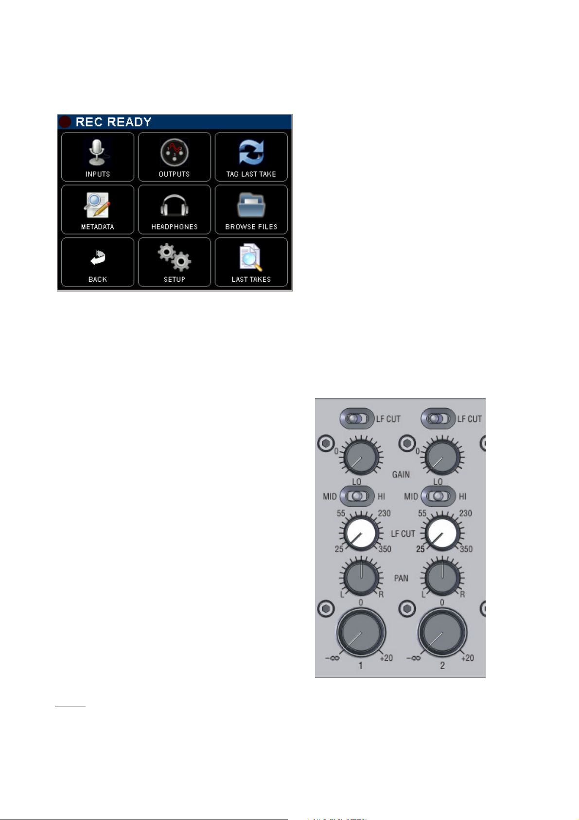
3. MAIN MENU
Pressing the main screen anywhere above the blue area will call the Main Set Up Menu. Pressing any key will
call a Sub-Menu
<= Indicated the status of the recorder
[INPUT] configure the input channels of the mixer
[OUTPUTS] configure the outputs of the mixer
[TAG LAST TAKE] tag as False start, Wild track,
No good or Circled
[METADATA] edit the Metadatas
[HEADPHONE] configure the Headphones
outputs
[BROWSE FILES] browse recorded takes in the
HD or CF card
[BACK] return to the main screen
[SETUP] configure all parameters of the recorder
[LAST TAKES] displays the last recorded takes
4. ANALOGUE MIXER SECTION
4.1 MIC/LINE INPUT
- Pre LF-Cut (135Hz at 6dB/octave)
(acting before the mic preamplifier)
- GAIN Trim +/- 20dB combined with the Gain preset
from -6dB up to 80dB of input Gain
- GAIN Preset
Mid 40dB (20 to 60dB) - Low12dB (-6 to 32dB)
High 60dB (40 to 80dB)
- Sweep LF Cut 20 to 350Hz at 12dB/octave
releasing the knob activates the PFL
(retractable potentiometer)
- PANORAMA configurable in the settings menu
- Rotating Fader from – infinite to +20dB
NOTE:
secondary functions are controlled by a specific menu explained in following chapters, such as
power On/Off, 48Vphantom, polarity (phase) reversal, Limiter threshold, Stereo link, M/S decoding,
Fader linking, channel assignment and routing,
SONOSAX SX62R Quick Start Guide Page 7 of 34
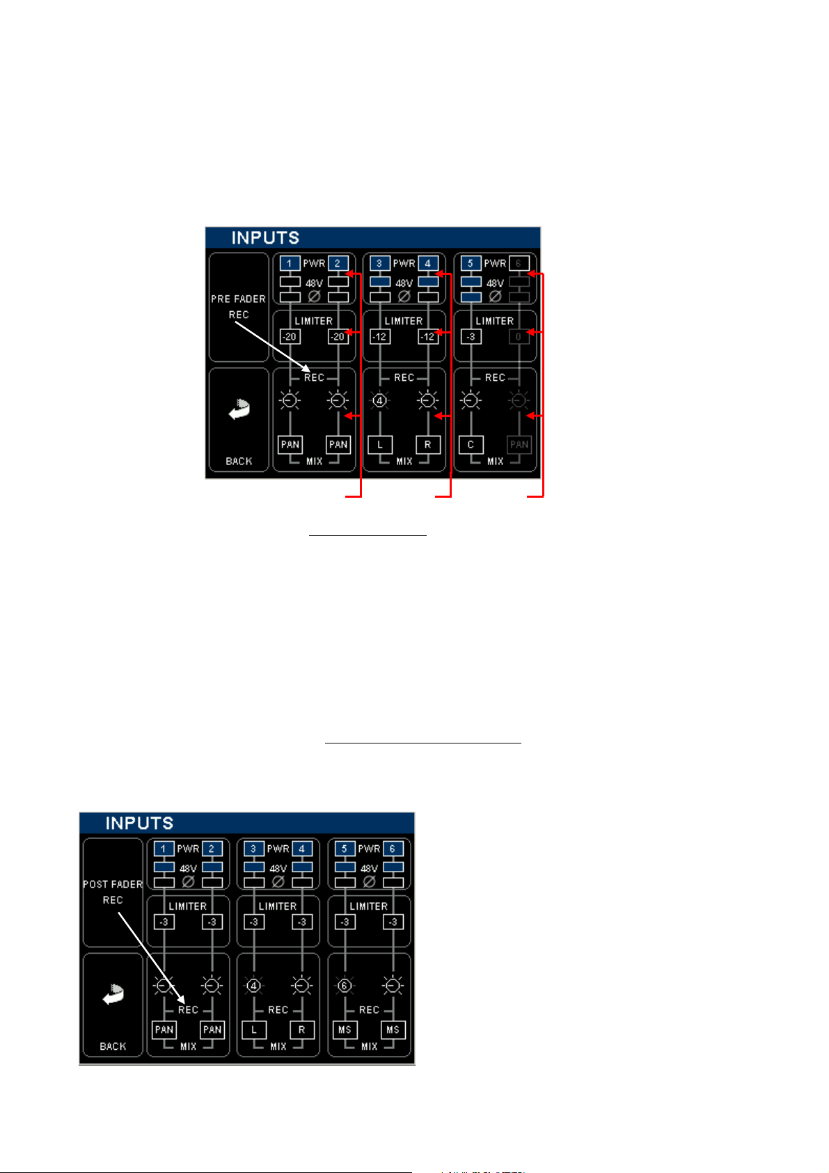
4.2 MIC/LINE INPUT CONFIGURATIONS
From the main menu, enter the inputs configuration page by touching the [INPUTS] key. A new screen is
posted, displaying the actual configuration of the input channels as illustrated below.
Each input channels of the analogue mixer can be configured individually; active (enabled) functions are highlighted in blue.
Touching a region (in a square) calls a specific sub menu to configure the channel's parameters.
Power On / Off
Toggle Pre or Post
Fader routing to the
recorder
Limiters Threshold
48V Phantom
Phase reversal
Returns to previous
Menu
Routing to the Mix Busses
Fader (Volume Control)
Assignment to the mix busses
Direct access to channels 1 & 2 3 & 4 5 & 6
The above example shows a typical "mixer configuration
input channels are recorded "Pre Fader" for back-up purposes:
" where the final mixing is done on location and the
- Input channels 1 to 5 are powered On; input channel 6 is powered Off to save on batteries
- Input channels 3 to 5 have the 48V phantom are turned On
- The Polarity of Input channels 5 is reversed.
- The Threshold level of each Limiter is indicated individually.
- All input channels are sent PRE Fader to the recorder [REC]
- Input channels 1 & 2 are assigned to the Mix Bus [MIX] through the [PAN] pot.
- Input channel 3 is assigned to the Left mix bus; channel 4 to the Right mix bus, [PAN] is disabled
- Faders of channels 3 & 4 are linked as stereo pair, Fader 4 controlling channels 3 & 4
- Input channels 5 is assigned in the centre [C]; equally to the Left and Right mix busses, the [PAN] is disabled
The following example shows a typical "Recorder setting with rough mix
"; the channels are sent Post Fader to
the Recorder, the Faders are used to control the recording level to optimize the S/N ratio and the resolution
over the entire dynamics range on the recorded tracks. In this case the analogue mix is recorded as a rough
mix only for editing purposes.
Input channels 1 to 6 are powered ON
48V Phantom is enabled on each input
No polarity reversal is active
The Limiter Threshold is set to -3dBFS to make use of
the full dynamic range. They protect the A/D Converter
leaving only 3dB of Headroom
Channels 1&2 are individually controlled by their own
fader
Channels 3&4 are linked as stereo pair , controlled by
fader 4
Channels 5& 6 are a M/S pair, controlled by fader 6, the
M/S signal is decoded
All channels are assigned on the mix busses
SONOSAX SX62R Quick Start Guide Page 8 of 34
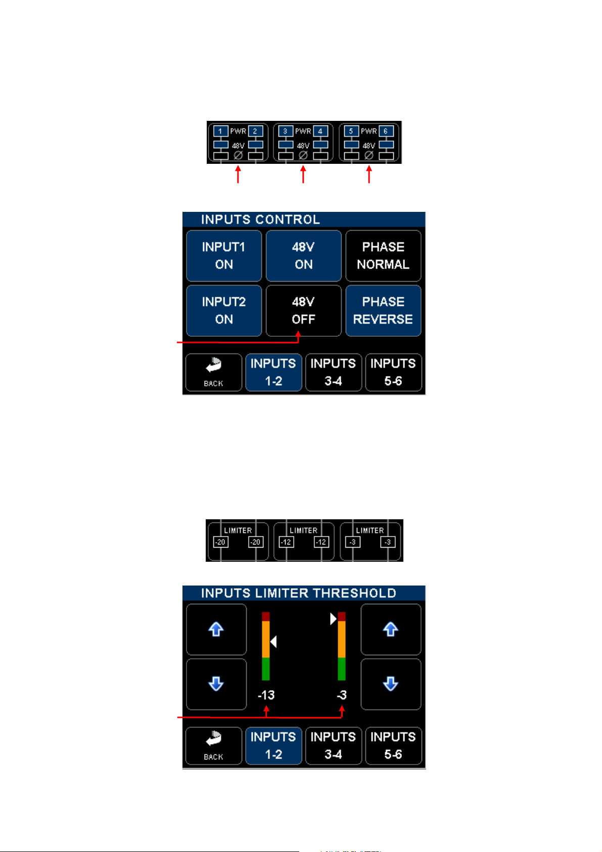
4.2.1 Input Controls
Touching any squared region on the Input Configuration Screen will call a sub-menu to set the parameters.
Active (or enabled parameters) are high lighted in blue.
Access to parameters of channels 1 & 2 3 & 4 5 & 6
Power the channel ON or
OFF to save on batteries
Toggle the 48V Phantom
ON or OFF
Return to
previous
menu
Active pair
of channels
Jump to
channel's
pair 3 & 4
Jump to
channel's pair
5 & 6
Toggle between Normal
Phase and Phase Reversal
4.2.2 Limiter Threshold
The Threshold of the Limiters can be individually adjusted on each input channel between 0dBFS to -29dBFS.
Touch a region to access the settings of the corresponding pairs.
1 & 2 3 & 4 5 & 6
Increase the Threshold in
step of 1 dB
Decrease the Threshold in
step of 1 dB
Indicates the Threshold
level below 0dBFS
SONOSAX SX62R Quick Start Guide Page 9 of 34
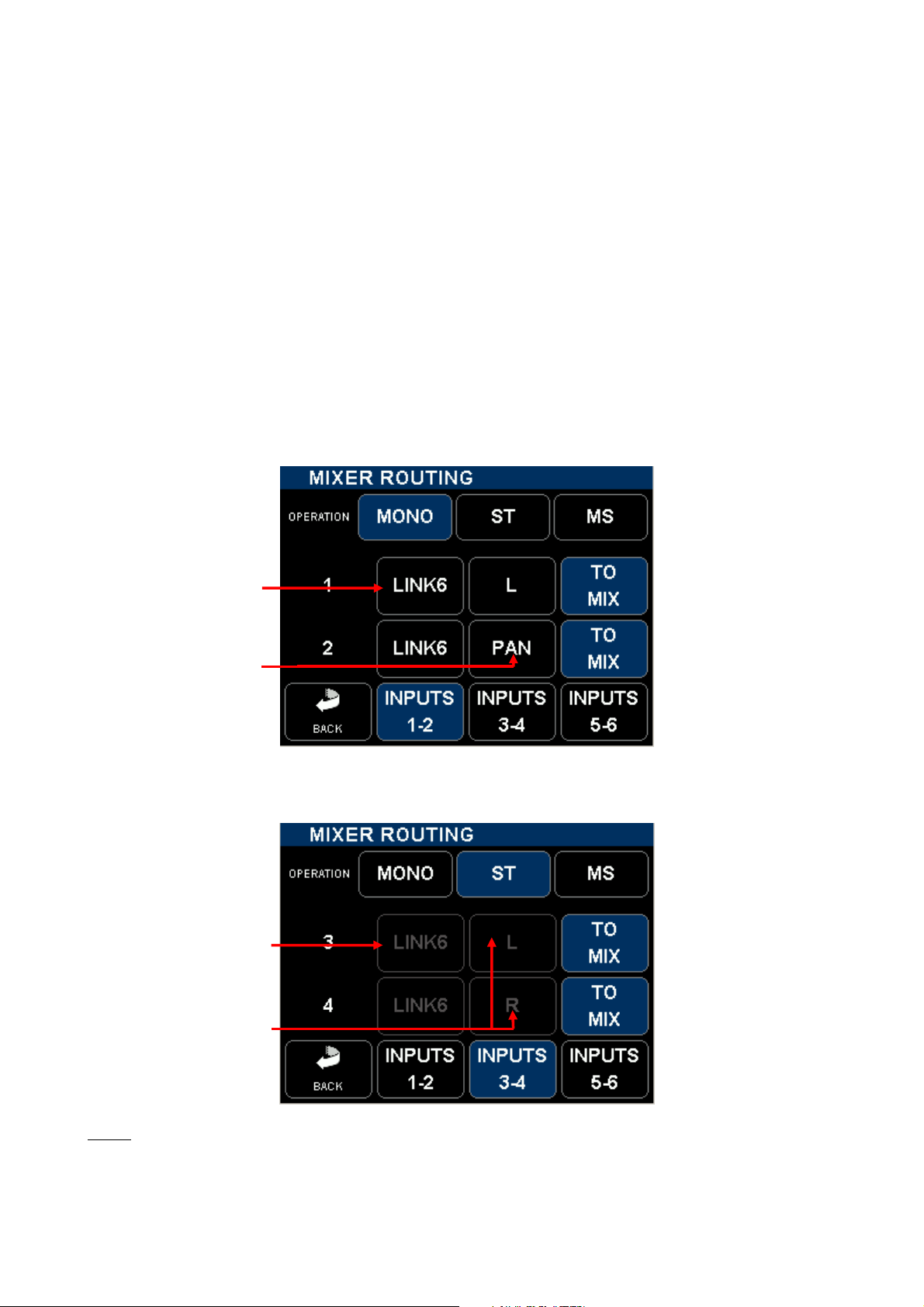
4.2.3 Input Assignment – Linking and Routing
Each input channels can be individually routed and assigned to the stereo mix bus. Input channels can be
configured either as a single MONO channel, as STEREO pair or an M/S pair.
- A [MONO] channel can be freely routed to the mix busses either to the Left [L] bus or to the Right [R] bus
only, or to the center [C] at the same level on the left and right busses, or through the panoramic [PAN] for a
progressive adjustment from Left to Right.
- A stereo pair [ST], such as a stereo microphone, must be always connected as a pair to the input channels
1-2 or 3-4 or 5- 6. Selecting [ST] automatically disables the routing selector [L-C-R-PAN] and route the Odd
channel to the Left mix bus and the Even channel to the Right mix bus. The Fader of the Odd channel is
automatically "Linked" to the Fader of the Even channel. A stereo pair can not be linked to channel 6
- An M/S microphone can be connected onto any pair of input channels 1-2 or 3-4 or 5- 6. Connect the M
channel on the Odd input and the S channel on the Even input. Selecting [M/S] decodes the modulation which
is sent to the mix bus with a 50/50 ratio. The Odd channel is automatically linked to the Even channel. Linking
to channel 6 can not be activated. Varying the spread of the MS pair can be done by slightly adjusting the
input Gain of the S channel. Select [ST] instead of [MS] to send a non decoded modulation to the mix bus.
Select between MONO, ST
or MS mode
If MONO is selected, the
channel can be Linked to
the fader of channel 6
If MONO is selected, the
toggle switch selects the
PAN – L – R or C routing
Return to the
Main Menu
Active pair
of channel
Jump to
channels 3-4
Jump to
channels 5-6
In this example [ST] is
selected
If [ST] or [MS] is selected,
the fader can not be linked
to fader nr 6
If [ST] or [MS] is selected
the routing PAN – L – R or
C is disabled
Assign the channel to the
mix bus
Assign the channel to the
mix bus
NOTE
: LINK 6 is used for multi-channel systems such as Soundfield microphones, double M-S system or
any Surround microphone system. It links the Faders only, not the Gain trim
SONOSAX SX62R Quick Start Guide Page 10 of 34

4.3 MASTER & MONITORING SECTION
This section details all functionalities related to the Main output, the dual Monitoring and its communication
system, the stereo Returns, the Slate and Tone generator as well as the COM microphone and the Auxiliary
output
- Main Monitor selector - Secondary Monitor selector
[BOOM]
Dedicated to the sound operator dedicated for the Boom or producer
REC: monitors the recorder REC: monitors the recorder
All other positions monitor the mixer All other positions monitor the mixer
- Volume control of the main monitor - Volume of the secondary monitor
[PHONES] on the side and front panels [BOOM] connector on the back panel
- MIC Level for SLATE & COM send - MIC Level for COM Return mic
(internal or external microphone) [BOOM] connector on the back panel
- SLATE Key - COM Key / Private line communication
- Master Fader of the Stereo Mix - Stereo RETURN volume control
Monitor selectors choose the source and the monitoring mode as below:
ST : Monitors the L & R Master Mix in stereo.
REC : Monitors the Tracks of the Recorder. This selection depends on the configuration in the
[HEADPHONES] menu.
RT: Monitors the [RETURN] input in stereo
RT/M: Monitors the [RETURN] input in mono
ST: same as above, duplicated for quick selection
REC: same as above, duplicated for quick selection
L: the Left channel of the Master Mix is listened in Mono on both ears.
R: the Right channel of the Master Mix is listened in Mono on both ears.
M: The summing of L & R master channels is eared in Mono. Listening in Mono offer a rapid
check of mono compatibility and helps detecting possible phase problem
MS: M-S decoder is engaged on the monitoring only
OFF: Secondary monitor only, its output is powered OFF to save on batteries
NOTE 1
: The MS decoder does not affect the Main outputs. It decodes the MS signal for monitoring
purposes only. The ratio of the MS decoder is set at 50%
NOTE 2: secondary functions are controlled by specific menus explained in following chapters
SONOSAX SX62R Quick Start Guide Page 11 of 34
 Loading...