

Page 1

®
SonicWall
SonicWave
200/400 Series
Deployment Guide
Page 2

Contents
Part 1. Hardware Overview and Configuration
Hardware Overview . . . . . . . . . . . . . . . . . . . . . . . . . . . . . . . . . . . . . . . . . . . . . . . . . . . . . . . . . . . . . . . . . 6
SonicWave 231c Hardware Overview . . . . . . . . . . . . . . . . . . . . . . . . . . . . . . . . . . . . . . . . . . . . . . . . . . . . . 7
SonicWave 231c Product Description . . . . . . . . . . . . . . . . . . . . . . . . . . . . . . . . . . . . . . . . . . . . . . . . . . 7
SonicWave 231c Ports and LEDs . . . . . . . . . . . . . . . . . . . . . . . . . . . . . . . . . . . . . . . . . . . . . . . . . . . . . . 8
SonicWave 224w Hardware Overview . . . . . . . . . . . . . . . . . . . . . . . . . . . . . . . . . . . . . . . . . . . . . . . . . . . . 11
SonicWave 224w Product Description . . . . . . . . . . . . . . . . . . . . . . . . . . . . . . . . . . . . . . . . . . . . . . . . 11
SonicWave 224w Ports and LEDs . . . . . . . . . . . . . . . . . . . . . . . . . . . . . . . . . . . . . . . . . . . . . . . . . . . . 12
SonicWave 231o Hardware Overview . . . . . . . . . . . . . . . . . . . . . . . . . . . . . . . . . . . . . . . . . . . . . . . . . . . . 15
SonicWave 231o Product Description . . . . . . . . . . . . . . . . . . . . . . . . . . . . . . . . . . . . . . . . . . . . . . . . 15
SonicWave 231o LED Activity . . . . . . . . . . . . . . . . . . . . . . . . . . . . . . . . . . . . . . . . . . . . . . . . . . . . . . . 17
SonicWave 432e and 432i
Hardware Overview . . . . . . . . . . . . . . . . . . . . . . . . . . . . . . . . . . . . . . . . . . . . . . . . . . . . . . . . . . . . . . . . . . . 19
SonicWave 432e and 432i Product Description . . . . . . . . . . . . . . . . . . . . . . . . . . . . . . . . . . . . . . . . . 19
SonicWave 432e and SonicWave 432i
Available Ports/Status LEDs . . . . . . . . . . . . . . . . . . . . . . . . . . . . . . . . . . . . . . . . . . . . . . . . . . . . . . . . . 20
SonicWave 432o Hardware Overview . . . . . . . . . . . . . . . . . . . . . . . . . . . . . . . . . . . . . . . . . . . . . . . . . . . . 22
SonicWave 432o Product Description . . . . . . . . . . . . . . . . . . . . . . . . . . . . . . . . . . . . . . . . . . . . . . . . 22
SonicWave 432o Available Ports/Status LEDs . . . . . . . . . . . . . . . . . . . . . . . . . . . . . . . . . . . . . . . . . . 23
1
Product Specifications . . . . . . . . . . . . . . . . . . . . . . . . . . . . . . . . . . . . . . . . . . . . . . . . . . . . . . . . . . . . . . . 24
SonicWave 200 Series Specifications . . . . . . . . . . . . . . . . . . . . . . . . . . . . . . . . . . . . . . . . . . . . . . . . . . . . . 25
SonicWave 400 Series Specifications . . . . . . . . . . . . . . . . . . . . . . . . . . . . . . . . . . . . . . . . . . . . .
Deployment Requirements per Model . . . . . . . . . . . . . . . . . . . . . . . . . . . . . . . . . . . . . . . . . . . . . . . . . 29
SonicWave 231c
Deployment Requirements . . . . . . . . . . . . . . . . . . . . . . . . . . . . . . . . . . . . . . . . . . . . . . . . . . . . . . . . . . . . . 30
SonicWave 224w
Deployment Requirements . . . . . . . . . . . . . . . . . . . . . . . . . . . . . . . . . . . . . . . . . . . . . . . . . . . . . . . . . . . . . 31
SonicWave 231o
Deployment Requirements . . . . . . . . . . . . . . . . . . . . . . . . . . . . . . . . . . . . . . . . . . . . . . . . . . . . . . . . . . . . . 32
SonicWave 432e and 432i
Deployment Requirements . . . . . . . . . . . . . . . . . . . . . . . . . . . . . . . . . . . . . . . . . . . . . . . . . . . . . . . . . . . . . 33
SonicWave 432o
Deployment Requirements . . . . . . . . . . . . . . . . . . . . . . . . . . . . . . . . . . . . . . . . . . . . . . . . . . . . . . . . . . . . . 34
Antenna Installation . . . . . . . . . . . . . . . . . . . . . . . . . . . . . . . . . . . . . . . . . . . . . . . . . . . . . . . . . . . . . . . . 35
Installing SonicWave 231o Antennas . . . . . . . . . . . . . . . . . . . . . . . . . . . . . . . . . . . . . . . . . . . . . . . . . . . . . 36
SonicWave 231o Approved Alternative Antenna . . . . . . . . . . . . . . . . . . . . . . . . . . . . . . . . . . . . . . . 36
Installing SonicWave 432e Antennas . . . . . . . . . . . . . . . . . . . . . . . . . . . . . . . . . . . . . . . . . . . . . . . . . . . . . 37
Installing SonicWave 432o Antennas . . . . . . . . . . . . . . . . . . . . . . . . . . . . . . . . . . . . . . . . . . . . . . . . . . . . . 38
Available Antennas for the SonicWave 432o . . . . . . . . . . . . . . . . . . . . . . . . . . . . . . . . . . . . . . . . . . . 38
. . . . . . . . 27
Connecting Cables . . . . . . . . . . . . . . . . . . . . . . . . . . . . . . . . . . . . . . . . . . . . . . . . . . . . . . . . . . . . . . . . . .40
Connecting Cables for SonicWave 231c . . . . . . . . . . . . . . . . . . . . . . . . . . . . . . . . . . . . . . . . . . . . . . . . . . . 41
SonicWall SonicWave Deployment Guide
Contents
2
Page 3

Connecting Cables for SonicWave 224w . . . . . . . . . . . . . . . . . . . . . . . . . . . . . . . . . . . . . . . . . . . . . . . . . . 42
Connecting Cables for SonicWave 231o . . . . . . . . . . . . . . . . . . . . . . . . . . . . . . . . . . . . . . . . . . . . . . . . . . 44
Connecting Cables for the SonicWave 432e and SonicWave 432i . . . . . . . . . . . . . . . . . . . . . . . . . . . . . . 46
Connecting Cables for the SonicWave 432o . . . . . . . . . . . . . . . . . . . . . . . . . . . . . . . . . . . . . . . . . . . . . . . 47
Power Requirements . . . . . . . . . . . . . . . . . . . . . . . . . . . . . . . . . . . . . . . . . . . . . . . . . . . . . . . . . . . . . . . . 48
Wireless Access Point
Placement Considerations . . . . . . . . . . . . . . . . . . . . . . . . . . . . . . . . . . . . . . . . . . . . . . . . . . . . . . . . . . . 49
Radio Frequency Barriers . . . . . . . . . . . . . . . . . . . . . . . . . . . . . . . . . . . . . . . . . . . . . . . . . . . . . . . . . . 49
RF Interference . . . . . . . . . . . . . . . . . . . . . . . . . . . . . . . . . . . . . . . . . . . . . . . . . . . . . . . . . . . . . . . . . . . 50
Mounting Wireless Access Points . . . . . . . . . . . . . . . . . . . . . . . . . . . . . . . . . . . . . . . . . . . . . . . . . . . . . 51
Mounting the SonicWave 231c . . . . . . . . . . . . . . . . . . . . . . . . . . . . . . . . . . . . . . . . . . . . . . . . . . . . . . . . . . 52
Mounting the SonicWave 224w . . . . . . . . . . . . . . . . . . . . . . . . . . . . . . . . . . . . . . . . . . . . . . . . . . . . . . . . . 55
Mounting the SonicWave 231o . . . . . . . . . . . . . . . . . . . . . . . . . . . . . . . . . . . . . . . . . . . . . . . . . . . . . . . . . 57
Mounting the SonicWave 432e and 432i . . . . . . . . . . . . . . . . . . . . . . . . . . . . . . . . . . . . . . . . . . . . . . . . . . 58
Mounting Using Anchor Screws . . . . . . . . . . . . . . . . . . . . . . . . . . . . . . . . . . . . . . . . . . . . . . . . . . . . . 62
Mounting the SonicWave 432o . . . . . . . . . . . . . . . . . . . . . . . . . . . . . . . . . . . . . . . . . . . . . . . . . . . . . . . . . 65
Ground Connection . . . . . . . . . . . . . . . . . . . . . . . . . . . . . . . . . . . . . . . . . . . . . . . . . . . . . . . . . . . . . . . 65
Mounting the SonicWave 432o on a Pole or Post . . . . . . . . . . . . . . . . . . . . . . . . . . . . . . . . . . . . . . . 65
Part 2. Software Configuration
Configuring SonicOS for
Wireless Access . . . . . . . . . . . . . . . . . . . . . . . . . . . . . . . . . . . . . . . . . . . . . . . . . . . . . . . . . . . . . . . . . . . . 67
Introduction . . . . . . . . . . . . . . . . . . . . . . . . . . . . . . . . . . . . . . . . . . . . . . . . . . . . . . . . . . . . . . . . . . . . . . . . . 67
Firewall-Based Configuration . . . . . . . . . . . . . . . . . . . . . . . . . . . . . . . . . . . . . . . . . . . . . . . . . . . . . . . 67
Cloud-Based Configuration . . . . . . . . . . . . . . . . . . . . . . . . . . . . . . . . . . . . . . . . . . . . . . . . . . . . . . . . . 68
Configuring SonicOS for 200 Series SonicWave Access Points . . . . . . . . . . . . . . . . . . . . . . . . . . . . . . . . . 69
Configuring the SonicWave Provisioning Profile . . . . . . . . . . . . . . . . . . . . . . . . . . . . . . . . . . . . . . . . 69
Configuring the Network Interface . . . . . . . . . . . . . . . . . . . . . . . . . . . . . . . . . . . . . . . . . . . . . . . . . . . 71
Configuring the WLAN Zone . . . . . . . . . . . . . . . . . . . . . . . . . . . . . . . . . . . . . . . . . . . . . . . . . . . . . . . . 72
Configuring SonicOS for 400 Series SonicWave Access Points . . . . . . . . . . . . . . . . . . . . . . . . . . . . . . . . . 73
Configuring the Network Interface . . . . . . . . . . . . . . . . . . . . . . . . . . . . . . . . . . . . . . . . . . . . . . . . . . . 73
Configuring the WLAN Zone . . . . . . . . . . . . . . . . . . . . . . . . . . . . . . . . . . . . . . . . . . . . . . . . . . . . . . . . 74
Configuring the 400 Series Access Point Settings . . . . . . . . . . . . . . . . . . . . . . . . . . . . . . . . . . . . . . . 75
Wireless Cloud Management Overview . . . . . . . . . . . . . . . . . . . . . . . . . . . . . . . . . . . . . . . . . . . . . . . . . . 77
WiFi Cloud Manager . . . . . . . . . . . . . . . . . . . . . . . . . . . . . . . . . . . . . . . . . . . . . . . . . . . . . . . . . . . . . . 77
WiFi Planner . . . . . . . . . . . . . . . . . . . . . . . . . . . . . . . . . . . . . . . . . . . . . . . . . . . . . . . . . . . . . . . . . . . . . 77
WiFi Cloud Manager Mobile App . . . . . . . . . . . . . . . . . . . . . . . . . . . . . . . . . . . . . . . . . . . . . . . . . . . . 77
Integration with other
SonicWall Software . . . . . . . . . . . . . . . . . . . . . . . . . . . . . . . . . . . . . . . . . . . . . . . . . . . . . . . . . . . . . . . . . 78
Part 3. Tests and Troubleshooting
Verifying Operation . . . . . . . . . . . . . . . . . . . . . . . . . . . . . . . . . . . . . . . . . . . . . . . . . . . . . . . . . . . . . . . . .80
Verifying SonicWave 200 series Operation . . . . . . . . . . . . . . . . . . . . . . . . . . . . . . . . . . . . . . . . . . . . . . . . 81
SonicWall SonicWave Deployment Guide
Contents
3
Page 4

Verifying SonicWave 400 Series Operation . . . . . . . . . . . . . . . . . . . . . . . . . . . . . . . . . . . . . . . . . . . . . . . . 82
Troubleshooting . . . . . . . . . . . . . . . . . . . . . . . . . . . . . . . . . . . . . . . . . . . . . . . . . . . . . . . . . . . . . . . . . . . 83
SonicWave 200 Series Troubleshooting . . . . . . . . . . . . . . . . . . . . . . . . . . . . . . . . . . . . . . . . . . . . . . . . . 84
SonicWave 400 Series Troubleshooting . . . . . . . . . . . . . . . . . . . . . . . . . . . . . . . . . . . . . . . . . . . . . . . . . . . 85
Part 4. Support and Product Registration
Registration and Support . . . . . . . . . . . . . . . . . . . . . . . . . . . . . . . . . . . . . . . . . . . . . . . . . . . . . . . . . . . . 87
Online Support and Training . . . . . . . . . . . . . . . . . . . . . . . . . . . . . . . . . . . . . . . . . . . . . . . . . . . . . . . . . . 88
Product Safety and Regulatory Information . . . . . . . . . . . . . . . . . . . . . . . . . . . . . . . . . . . . . . . . . . . . . 89
Glossary . . . . . . . . . . . . . . . . . . . . . . . . . . . . . . . . . . . . . . . . . . . . . . . . . . . . . . . . . . . . . . . . . . . . . . . . . . 90
SonicWall Support . . . . . . . . . . . . . . . . . . . . . . . . . . . . . . . . . . . . . . . . . . . . . . . . . . . . . . . . . . . . . . . . . .93
About This Document . . . . . . . . . . . . . . . . . . . . . . . . . . . . . . . . . . . . . . . . . . . . . . . . . . . . . . . . . . . . . . . . . 94
SonicWall SonicWave Deployment Guide
Contents
4
Page 5

1
Hardware Overview and Configuration
• Hardware Overview
• Product Specifications
• Deployment Requirements per Model
• Antenna Installation
• Connecting Cables
• Power Requirements
• Wireless Access Point Placement Considerations
• Mounting Wireless Access Points
SonicWall SonicWave Deployment Guide
Hardware Overview and Configuration
5
Page 6

Hardware Overview
This summarizes salient and visible differences among SonicWave 200 and 400 series access points.
To pi cs :
• SonicWave 231c Hardware Overview
• SonicWave 224w Hardware Overview
• SonicWave 231o Hardware Overview
• SonicWave 432e and 432i Hardware Overview
• SonicWave 432o Hardware Overview
1
SonicWall SonicWave Deployment Guide
Hardware Overview
6
Page 7
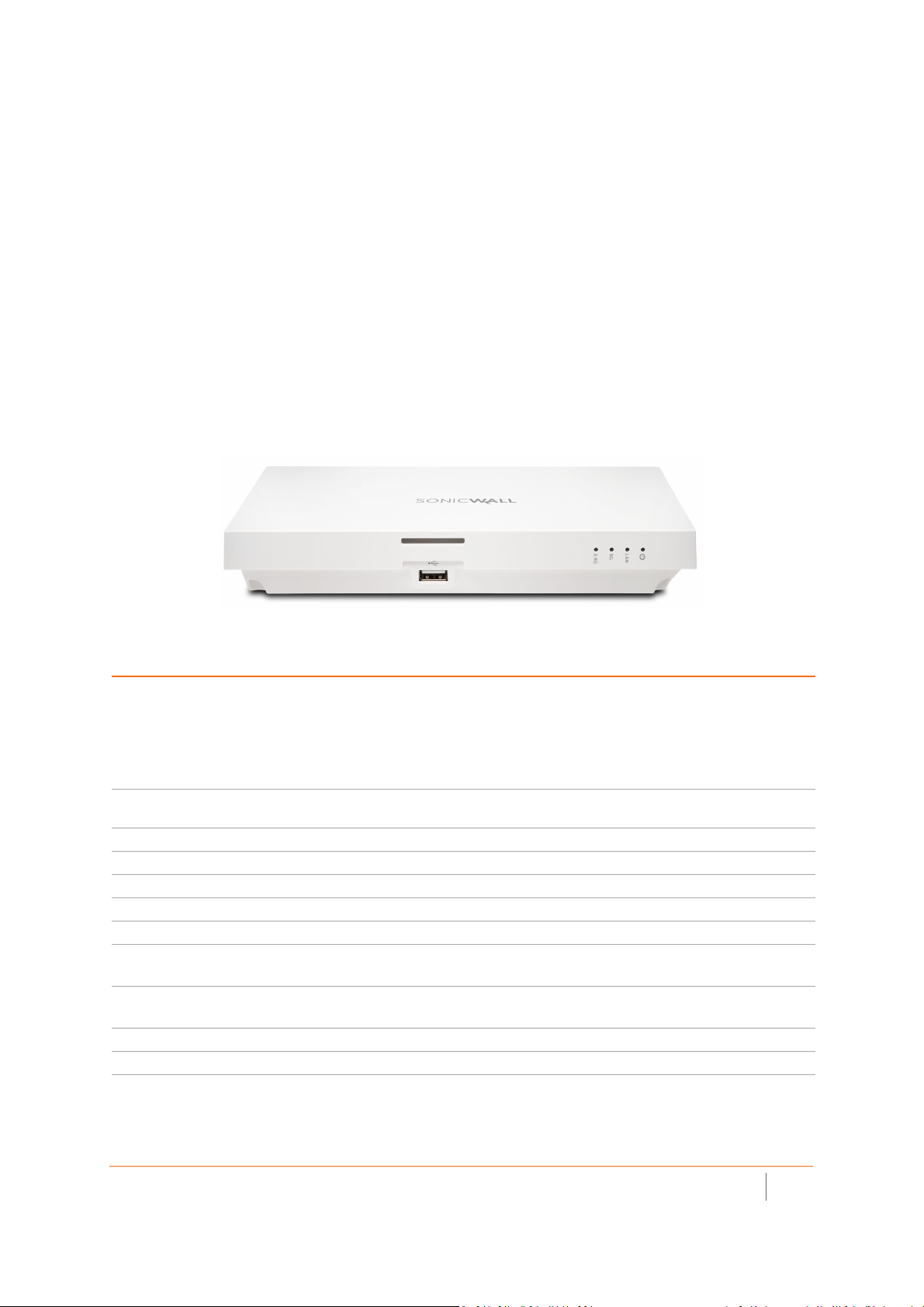
SonicWave 231c Hardware Overview
SonicWave 231c Product Description
Salient features of the SonicWave 231c include:
• Ceiling mount design / mount on ceiling or wall
• Plenum-rated for safe ceiling use
• 2 x 2 MU-MIMO
• Ethernet: 1 x10/100/1000 auto-sensing RJ 45
• USB 2.0 interface
• 802.3AT PoE power supply with optional 12 V adapter
SonicWave 231c
SonicWave 231c Hardware Components
Component Description
2.4GHz and 5GHz radios Dual radios provide:
• 802.11b/g/n/ac
• DFS (Dynamic Frequency Selection)
SonicWave 231c complies with FCC rules to detect and avoid interfering with radar
signals in DFS bands.
• 2x2 11n + 2x2 11ac Wave 2 MU-MIMO
1GbE LAN port 1 Ethernet 10/100/1000 LAN port for wired connection to a SonicWall network security
USB port 1 USB 2.0 port
Flash memory 256 MB NAND Flash
DDR Memory 512 MB DDR3-1600MHz
Scanning radio Dedicated third scanning radio
Antennas 5 internal (2.4Ghz x 2 / 5Ghz x 2 / Scan Radio x 1)
Power source 802.3at PoE (standard, PoE device sold separately)
Chassis Rectangle 119mm x 214mm x 34mm
Kensington security slot For use with a Kensington locking cable to prevent theft
Operating temperature 0° to 40°C
appliance
Optional DC 12V power adapter, sold separately
Plenum rated
SonicWall SonicWave Deployment Guide
Hardware Overview
7
Page 8
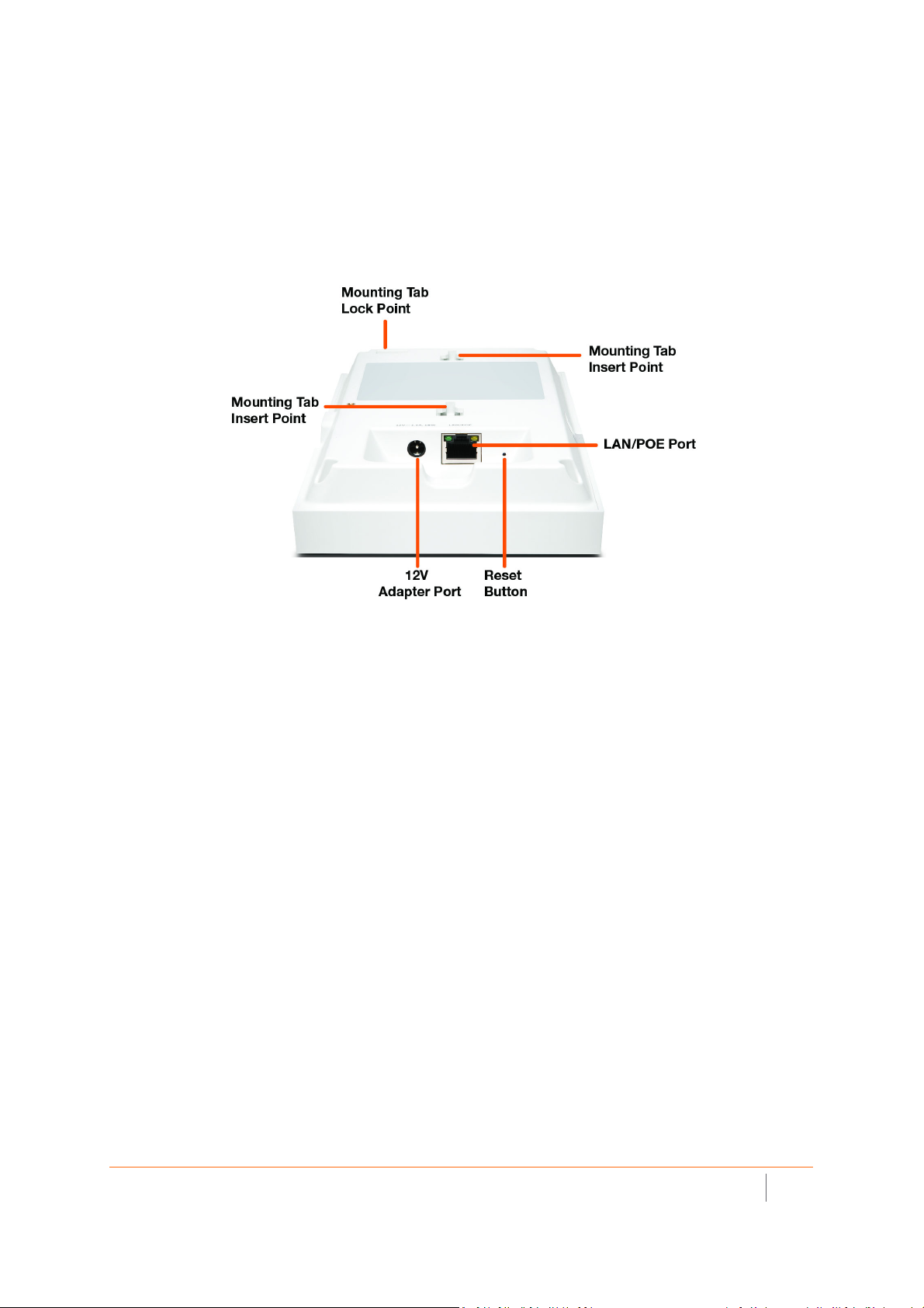
SonicWave 231c Ports and LEDs
The back of SonicWave 231c provides a LAN/POE port where the PoE Ethernet cable connects the access point
with the PoE injector or PoE-enabled switch, which connects to your SonicWall network security appliance.
A 12V power connection is also provided on the back of the unit, where you can plug in a 12V adapter (sold
separately) to power the device.
SonicWave 231c Back
When the access point is installed, the back panel is attached to the ceiling or to a wall or other flat surface.
SonicWall SonicWave Deployment Guide
Hardware Overview
8
Page 9
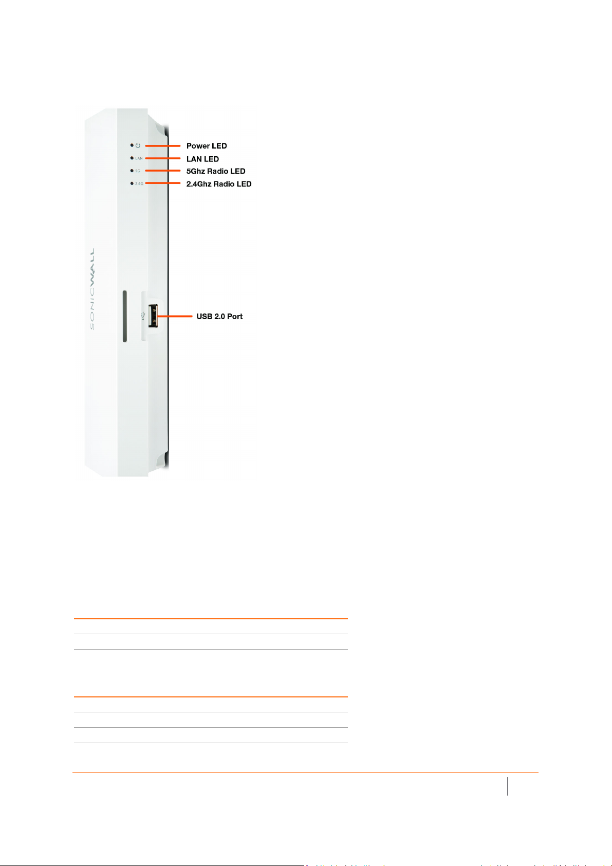
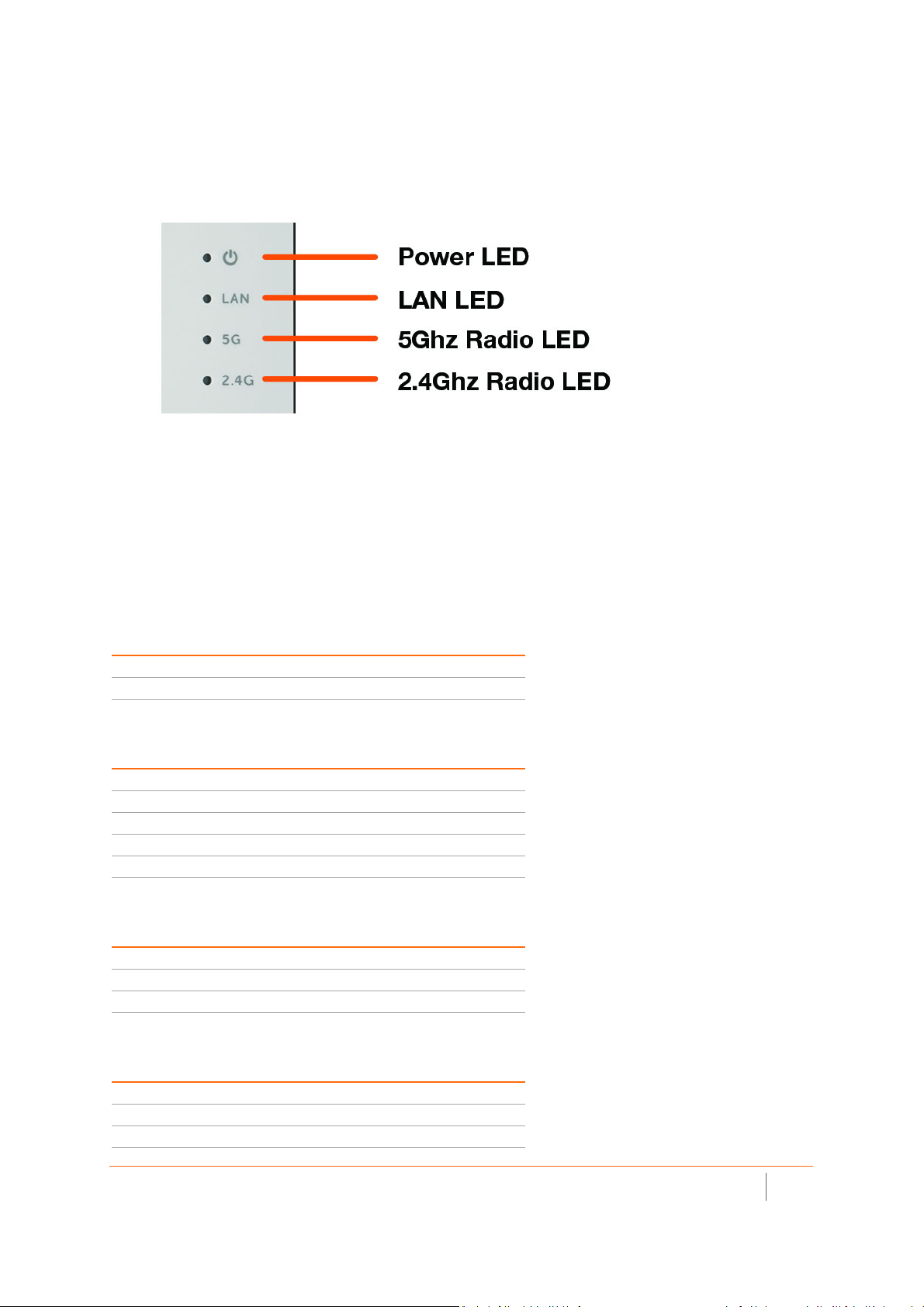
The side panel of the SonicWave 231c has the LED indicators and the USB port.
SonicWave 231c LEDs
You can insert a 3G/4G USB modem into the USB port to create a mobile wireless (MiFi) hotspot. See the
SonicOS 6.5 Connectivity administration documentation for information about the MiFi Extender feature. You
can also use the USB port with a USB security clamp.
SonicWave 231c LED Activity
The SonicWave 231c LEDs provide essential status information about the access point.
Power LED
LED Color Description
Off No power
Blue Power is on
LAN LED
LED Color Description
Off No link
Solid Yellow Link established at 1 Gbps
Blinking Yellow Active traffic at 1 Gbps
SonicWall SonicWave Deployment Guide
Hardware Overview
9
Page 10

LAN LED
LED Color Description
Solid Green Link established at 100 Mbps or 10 Mbps
Blinking Green Active traffic at 100 Mbps or 10 Mbps
5 GHz Radio LED
LED Color Description
Off 5 GHz radio is off
Solid Green 5 GHz radio is on
Blinking Green Active traffic on 5 GHz radio
2.4 GHz Radio LED
LED Color Description
Off 2.4 GHz radio is off
Solid Green 2.4 GHz radio is on
Blinking Green Active traffic on 2.4 GHz radio
LED Pattern During Firmware or SafeMode Bootup
LEDs LED Color Description
LAN Green - Heartbeat The three LEDs blink simultaneously in a
5 GHz Radio Green - Heartbeat
2.4 GHz Radio Green - Heartbeat
heartbeat pattern while booting is in
progress:
On - On - Off
LED Pattern for Reset Button Hold Durations
LEDs LED Color Description
LAN Blinking Green The three LEDs blink simultaneously at a slow
5 GHz Radio Blinking Green
2.4 GHz Radio Blinking Green
or medium rate:
• Slow blink – Press Reset button 3 sec
• Med blink – Press Reset button 8 sec
LED Pattern in SafeMode
LEDs LED Color Description
LAN Green - Flow The three LEDs turn on serially (one by one)
5 GHz Radio Green - Flow
2.4 GHz Radio Green - Flow
NOTE: The LEDs are disabled by default. You can enable them in the SonicWave
provisioning profile or individual SonicWave entry in SonicOS on the firewall.
and then turn off serially in a flow pattern
while the <Short Product Name> is in
SafeMode.
SonicWall SonicWave Deployment Guide
Hardware Overview
10
Page 11
SonicWave 224w Hardware Overview
SonicWave 224w Product Description
Distinguishing features of the SonicWave 224w include:
• Wall-mount design / mount on ceiling or wall
• 2 x 2 MU-MIMO
• Ethernet: 3 x 10/100/1000, 2x 10/100/1000 pass-through ports supporting PoE
• 802.3at PoE power supply with optional 12 V adapter
• PoE output: 802.3af
• Accessible (after mounting) reset button
SonicWave 224w
SonicWave 224w Hardware Components
Component Description
2.4GHz and 5GHz radios Dual radios provide:
• 802.11b/g/n/ac
• DFS (Dynamic Frequency Selection)
SonicWave 224w complies with FCC rules to detect and avoid interfering
with radar signals in DFS bands.
• 2x2 11n + 2x2 11ac MU-MIMO
1GbE LAN ports 3 Ethernet 10/100/1000 LAN ports for wired connections to a SonicWall
network security appliance
Pass through LAN port 1 Ethernet 10/100/1000 pass through LAN port pair for a separate network
connection from the same wall jack
LAN PoE Out port 1 LAN PoE Out port for 802.3af device
Flash memory 256 MB NAND Flash
DDR Memory 512 MB DDR3-1600MHz
Antennas 4 internal (2.4Ghz x 2 / 5Ghz x 2)
Power source 802.3at PoE (standard, PoE device sold separately)
Optional DC 12V power adapter, sold separately
Chassis Rectangle 122mm x 188mm x 18mm
Kensington security slot For use with a Kensington locking cable to prevent theft
Operating temperature 0° to 40°C
SonicWall SonicWave Deployment Guide
Hardware Overview
11
Page 12
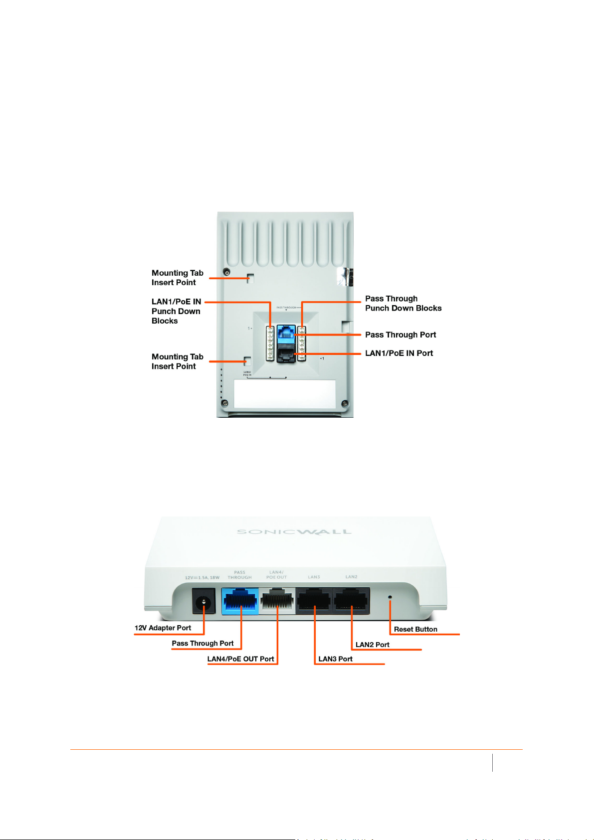
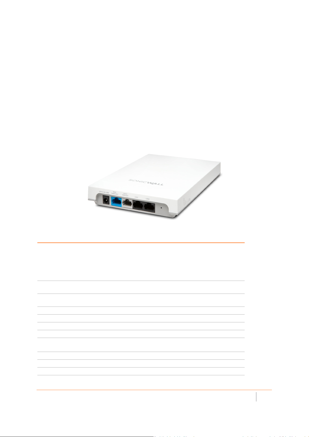
SonicWave 224w Ports and LEDs
The SonicWave 224w is a “wall jack” access point. The back of the device provides two LAN ports, a LAN1/PoE
IN port where the PoE Ethernet cable connects the access point with the PoE injector or PoE-enabled switch,
and one port of the LAN Pass Through port pair.
Punch down blocks are also provided for both LAN1/PoE IN and Pass Through. For the LAN1/PoE IN
connection, pin 1 of the Ethernet connector connects to the top left punch down block (labeled as 1>). For the
Pass Through connection, pin 1 of the Ethernet connector connects to the bottom right punch-down block
(labeled as <1). The rest of the pins are laid out in sequential order from 1-8.
SonicWave 224w Back
When the access point is installed, the back panel is attached to the wall or to a junction box.
The blue Pass Through port is directly connected to the blue Pass Through port on the bottom edge of the unit.
Neither of these ports access any functionality in the SonicWave 224w, but they provide a way for you to
connect to a second network available in the same wall jack that provides your PoE-enabled network
connection.
224w Ports on Bottom Edge
Other ports on the bottom edge of the SonicWave 224w include a power connection where you can plug in a
12V adapter (optional), and the LAN4/PoE OUT port which provides power over Ethernet for an 802.3af device,
such as an IP camera.
The LAN2 and LAN3 ports provide a way for you to connect directly to the SonicWave 224w over Ethernet for
access to the Internet or internal networks via the SonicWall firewall that is connected to the SonicWave 224w.
The side panel of the SonicWave 224w has the LED indicators.
SonicWall SonicWave Deployment Guide
Hardware Overview
12
Page 13
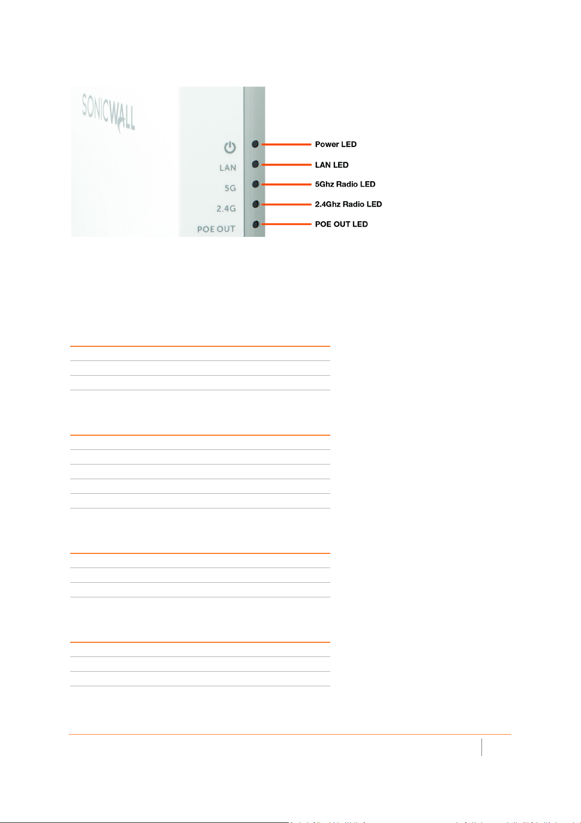
SonicWave 224 LEDs
For information about the LEDs, see the SonicWave 224w LED Activity section.
SonicWave 224w LED Activity
The SonicWave 224w LEDs provide essential status information about the access point.
Power LED
LED Color Description
Off No power
Blue Power source is AT (802.3at)
Yellow Power source is not AT
LAN LED
LED Color Description
Off No link
Solid Yellow Link established at 1 Gbps
Blinking Yellow Active traffic at 1 Gbps
Solid Green Link established at 100 Mbps or 10 Mbps
Blinking Green Active traffic at 100 Mbps or 10 Mbps
5 GHz Radio LED
LED Color Description
Off 5 GHz radio is off
Solid Green 5 GHz radio is on
Blinking Green Active traffic on 5 GHz radio
2.4 GHz Radio LED
LED Color Description
Off 2.4 GHz radio is off
Solid Green 2.4 GHz radio is on
Blinking Green Active traffic on 2.4 GHz radio
SonicWall SonicWave Deployment Guide
Hardware Overview
13
Page 14

PoE OUT LED
LED Color Description
Off PoE power output is disabled
Solid Green PoE power output is enabled
LED Pattern During Firmware or SafeMode Bootup
LEDs LED Color Description
LAN Green - Heartbeat The three LEDs blink simultaneously in a
5 GHz Radio Green - Heartbeat
2.4 GHz Radio Green - Heartbeat
heartbeat pattern while booting is in
progress:
On - On - Off
LED Pattern for Reset Button Hold Durations
LEDs LED Color Description
LAN Blinking Green The three LEDs blink simultaneously at a slow
5 GHz Radio Blinking Green
2.4 GHz Radio Blinking Green
or medium rate:
• Slow blink – Press Reset button 3 sec
• Med blink – Press Reset button 8 sec
LED Pattern in SafeMode
LEDs LED Color Description
LAN Green - Flow The three LEDs turn on serially (one by one)
5 GHz Radio Green - Flow
2.4 GHz Radio Green - Flow
and then turn off serially in a flow pattern
while the SonicWave 224w is in SafeMode.
NOTE: The LEDs are disabled by default. You can enable them in the SonicWave
provisioning profile or individual SonicWave entry in SonicOS on the firewall.
SonicWall SonicWave Deployment Guide
Hardware Overview
14
Page 15
SonicWave 231o Hardware Overview
SonicWave 231o Product Description
Because this product has unique market and functionality, the SonicWave 231o requires specially trained
professionals to configure and install it. Also, according to FCC rules (similar rules in other regulatory domains),
you are required to consult with an experienced professional RF installer/dealer/technician to conduct the
installation, conform to the regulation, and correct the interference from the standard industry measures. The
FCC requires you to be notified that any changes or modifications made to the device, that are not expressly
approved by SonicWall, could void your authority to operate the equipment. A professional installer is
responsible for the proper installation and configuration of the outdoor SonicWave. The installer needs to
understand and prepare for operating near any Terminal Doppler Weather Radar (TDWR) locations based on the
FCC Memorandum and comply with all its requirements. The professional installer needs to choose the correct
antenna type and its gain should be so chosen that the equivalent isotropically radiated power (EIRP) is not
more than that required for successful communication to ensure the reduction of potential radio interference
with other users. The professional installer must also properly select the current country of operation from the
SonicWall configuration interface. Incorrectly entering the country of operation could result in illegal operation
and might cause harmful interference to other systems.
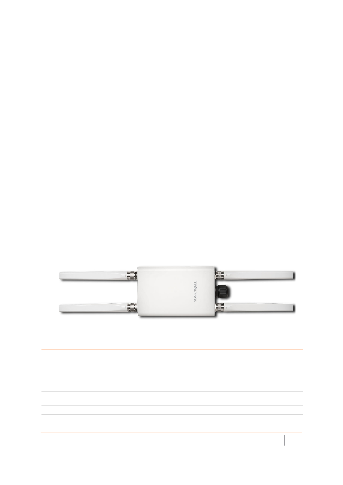
Distinguishing features of the SonicWave 231o include:
• For outdoor application, licensed installer required.
• 2 x 2 MU-MIMO
• NEMA mounting kit / 4 external, omni-directional antennas.
• Ethernet: 1 x 10/100/1000 auto-sensing RJ-45
• PoE in: 802.11af
SonicWave 231o Top
SonicWave 231o Hardware Components
Component Description
2.4GHz and 5GHz radios Dual radios provide:
• 802.11b/g/n/ac
• DFS (Dynamic Frequency Selection)
SonicWave 231o complies with FCC rules to detect and avoid interfering with radar
signals in DFS bands.
• 2x2 11n + 2x2 11ac wave 2 MU-MIMO
1GbE LAN port 1 Ethernet 10/100/1000 LAN port for wired connection to a SonicWall network security
appliance
Flash memory 256 MB NAND Flash
DDR Memory 512 MB DDR3-1600MHz
SonicWall SonicWave Deployment Guide
Hardware Overview
15
Page 16
SonicWave 231o Hardware Components
Component Description
Scanning radio Dedicated third scanning radio
Antennas 4 external Omni-Antenna (2.4Ghz x 2 / 5Ghz x 2)
1 internal antenna for scanning radio
Power source 802.3af PoE (standard, PoE device sold separately)
Chassis Rectangle 122mm x 188mm x 18mm
Plenum rated
Operating temperature -30° to 60°C
NOTE: The SonicWave 231o enclosure is IP67 compliant with components supplied with the
product and when installed as instructed.
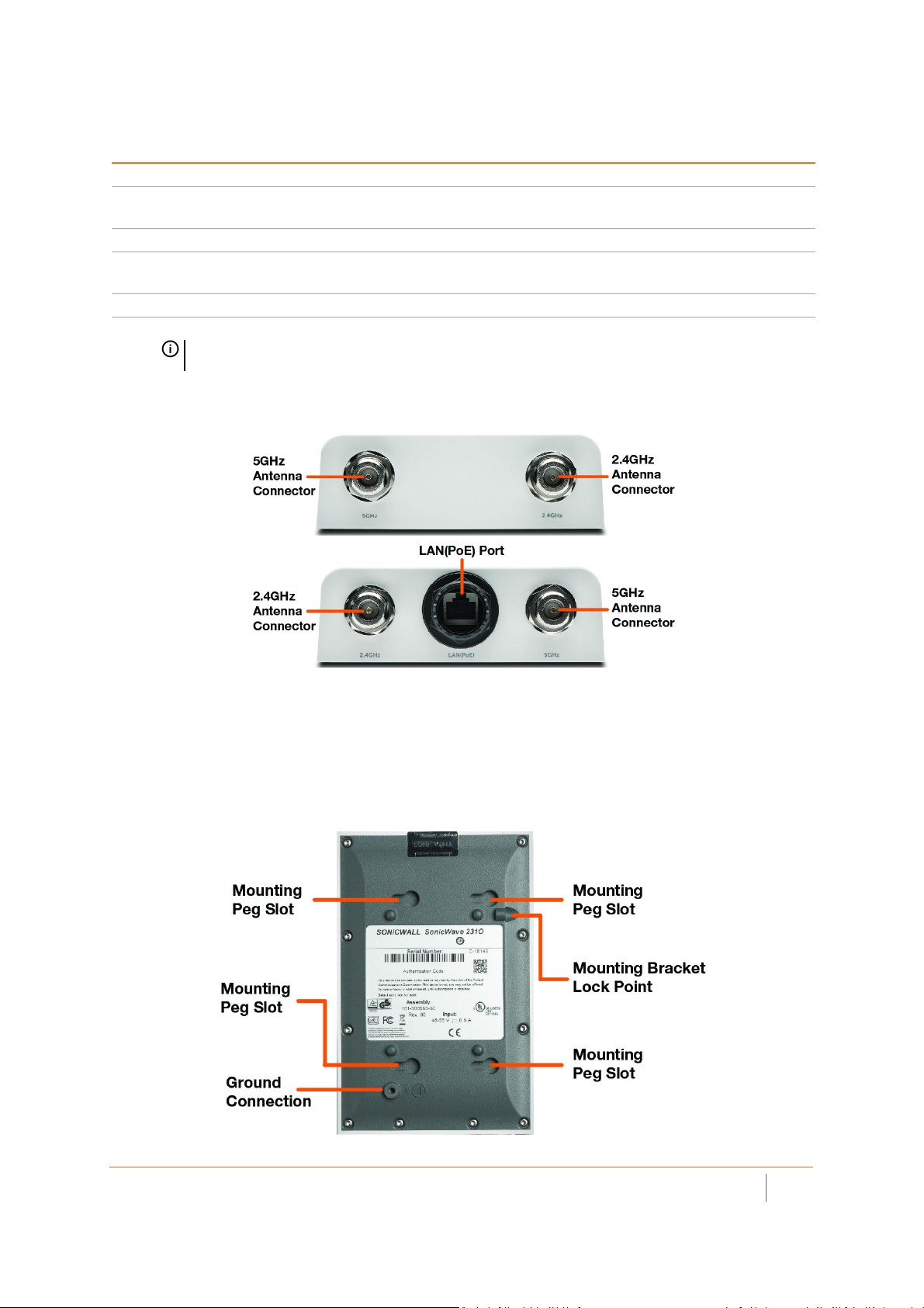
SonicWave 231o Antenna Connectors and LAN(PoE) Port
Four antenna ports on the ends of the SonicWave 231o provide connection points for the two 5GHz antennas
and two 2.4GHz antennas.
The SonicWave 231o provides one LAN(PoE) port for connecting to the PoE injector or PoE-enabled switch and
to your SonicWall network security appliance. You can also use a SonicWall PoE-enabled security appliance to
provide PoE from the appliance itself.
SonicWave 231o Bottom
SonicWall SonicWave Deployment Guide
Hardware Overview
16
Page 17
The bottom of the SonicWave 231o has four slots for inserting the pegs on the mounting bracket, and a
threaded hole for the mounting bracket locking screw. The ground connection point is also on the bottom of the
device.
SonicWave 231o LEDs
The side panel of the SonicWave 231o has the LED indicators.
For information about the LEDs, see the SonicWave 224w LED Activity section.
SonicWave 231o LED Activity
The SonicWave 231o LEDs provide essential status information about the access point.
Power LED
LED Color Description
Off No power
Blue Power is on
LAN LED
LED Color Description
Off No link
Solid Yellow Link established at 1 Gbps
Blinking Yellow Active traffic at 1 Gbps
Solid Green Link established at 100 Mbps or 10 Mbps
Blinking Green Active traffic at 100 Mbps or 10 Mbps
5 GHz Radio LED
LED Color Description
Off 5 GHz radio is off
Solid Green 5 GHz radio is on
Blinking Green Active traffic on 5 GHz radio
2.4 GHz Radio LED
LED Color Description
Off 2.4 GHz radio is off
Solid Green 2.4 GHz radio is on
Blinking Green Active traffic on 2.4 GHz radio
SonicWall SonicWave Deployment Guide
Hardware Overview
17
Page 18

LED Pattern During Firmware Bootup
LEDs LED Color Description
LAN Green - Heartbeat The three LEDs blink simultaneously in a heartbeat
5 GHz Radio Green - Heartbeat
2.4 GHz Radio Green - Heartbeat
NOTE: The LEDs are disabled by default. You can enable them in the SonicWave provisioning
profile or individual SonicWave entry in SonicOS on the firewall.
pattern while booting is in progress:
On - On - Off
SonicWall SonicWave Deployment Guide
Hardware Overview
18
Page 19

SonicWave 432e and 432i Hardware Overview
SonicWave 432e and 432i Product Description
The SonicWave 432e provides physical layer enhancements over earlier SonicWall access points for higher
throughput with a maximum data rate of 1.3 Gbps. To achieve this, the SonicWave 432e uses:
• More antennas—three antennas for the 5 GHz radio, and three more for the 2.4 GHz radio
• Wider channels—80 MHz-wide channels for the 802.11ac radio module, while continuing to support
20/40 MHz channels. This allows for dynamic per packet negotiation of channel widths so that when
there is interference, the SonicWave can temporarily fall back to 40 or 20MHz channels.
• More spatial streams—4 x 4 multiple-input and multiple-output, (MIMO) for the 802.11ac radio module,
where the capacity of a radio link is multiplied using multipath propagation.
Salient features of the SonicWave 432e and 432i include:
• For indoor use with wall / ceiling mount
• 4 x 4 MU-MIMO
• 432e with external high-gain antennas (4 x 4) and 432i with 8 internal antennas
• LAN1 supports up to 2.5 GbE and 802.3at PoE
• LAN2 supports 10/100/1000 MbE
• USB 2.0
• Ethernet console port (RJ 45)
SonicWall SonicWave Deployment Guide
Hardware Overview
19
Page 20
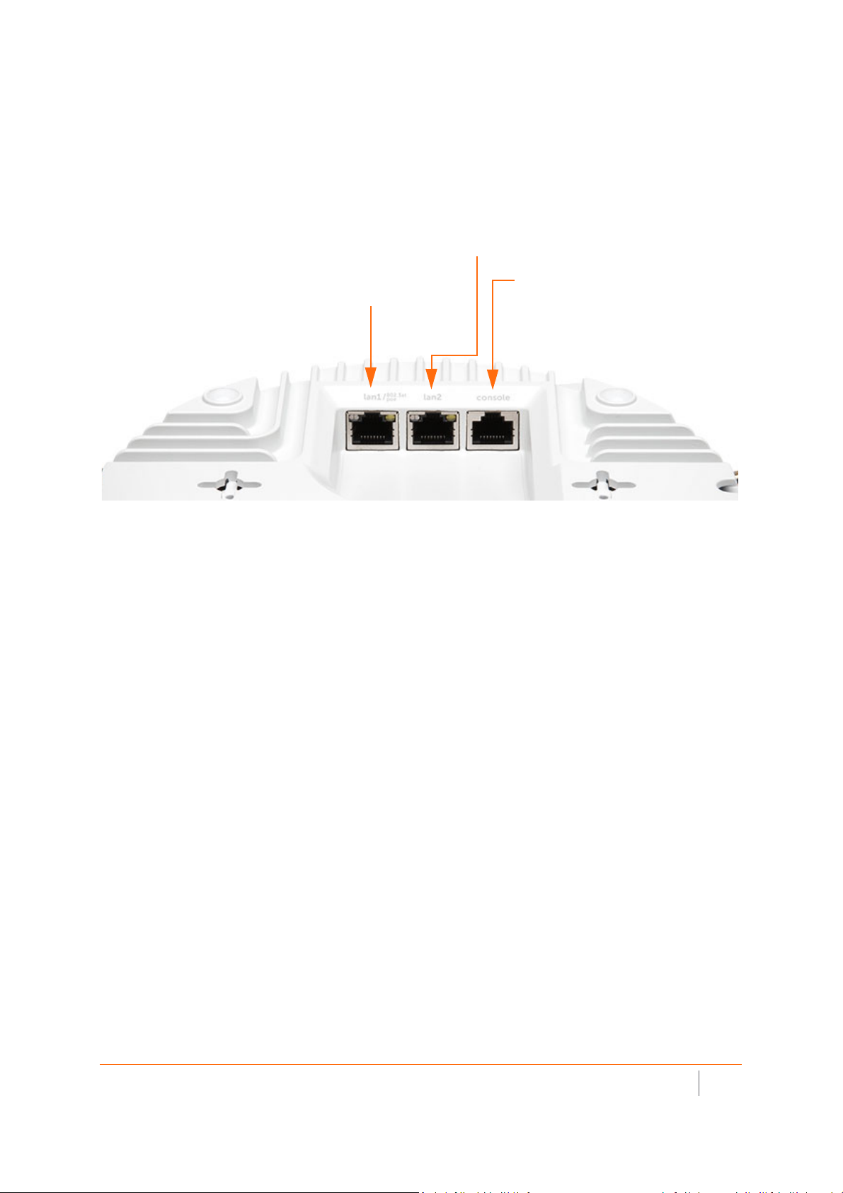
SonicWave 432e and SonicWave 432i
LAN1/PoE port.
Provides Ethernet and Power
over Ethernet (PoE)
LAN2 port.
Provides an additional Ethernet connection. Refer
to the SonicOS Connectivity Administration
documentation for use cases.
Console port.
Provides a management connection using
RJ45 to DB9 cable (for command line
Available Ports/Status LEDs
Available Ports
SonicWall SonicWave Deployment Guide
Hardware Overview
20
Page 21
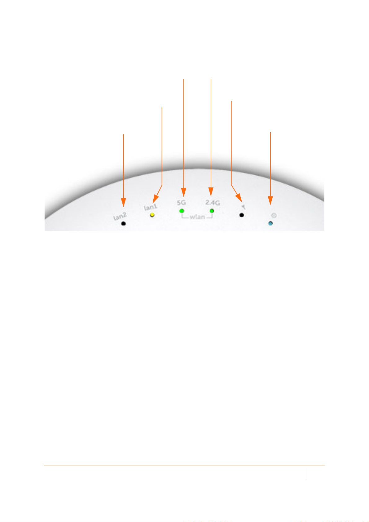
Status LEDs
LED (lan2)
- On (solid yellow or green, Ethernet link)
- Blinking yellow (1G Ethernet activity)
- Blinking green (10/100M Ethernet activity)
LED (lan1)
- On (solid yellow or green, Ethernet link)
- Blinking yellow (2.5G Ethernet activity)
- Blinking green (1G/100M Ethernet activity)
LED (5G)
- On (solid green, 5 GHz radio link)
- Blinking green (5 GHz radio activity)
LED (2.4G)
- On (solid green, 2.4 GHz radio link)
- Blinking (2.4 GHz radio activity)
LED (Tool)
- On (solid yellow, error)
- Blinking (safe mode)
LED (Power)
- On (solid blue, power)
- Blinking (booting/FW upgrade)
SonicWall SonicWave Deployment Guide
Hardware Overview
21
Page 22

SonicWave 432o Hardware Overview
SonicWave 432o Product Description
The SonicWave 432o extends your wireless LAN past the traditional boundaries of indoor locations. With state
of the art design and construction, it is resistant to harsh outdoor environments and extreme temperature
changes. The unit is designed specifically for outdoor use and can be attached to either a pole or wall.
Waterproof connectors are supplied to ensure watertight seals for connecting the Ethernet cables to the device.
The SonicWave 432o also provides physical layer enhancements for higher throughput with a maximum data
rate of 1.3 Gbps. To achieve this, the SonicWave 432o uses:
• More antennas—four antennas for the 5 GHz radio, and four more for the 2.4 GHz radio
• Wider channels—80 MHz-wide channels for the 802.11ac radio module, while continuing to support
20/40 MHz channels. This allows for dynamic per packet negotiation of channel widths so that when
there is interference, the SonicWave can temporarily fall back to 40 or 20MHz channels.
• More spatial streams—4 x 4 multiple-input and multiple-output, (MIMO) for the 802.11ac radio module,
where the capacity of a radio link is multiplied using multipath propagation.
Because of potential EMI issues, professional installation by a properly licsened specialist is required for the
SonicWave 432o.
Distinguishing features of the SonicWave 432o include:
• Antennas: 8 N-type dipole
• 4 x 4 MU-MIMO
• Ethernet: 1 x 10/100/1000 and 1 x 10/100/1000/2.5 GbE
• PoE: 802.3at in; 802.3af out
• Ethernet console port (RJ5)
SonicWall SonicWave Deployment Guide
Hardware Overview
22
Page 23
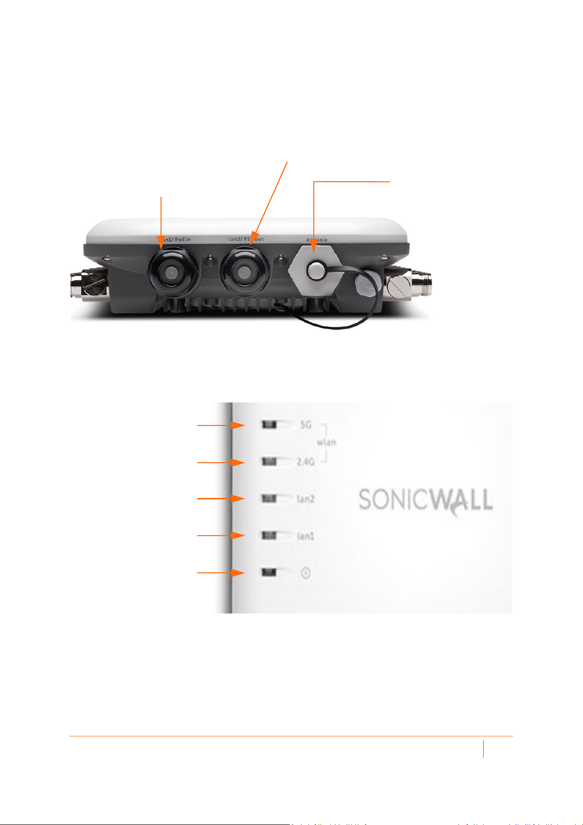
SonicWave 432o Available Ports/Status LEDs
lan2/PSE out port.
Provides an additional Ethernet connection. Refer to
the SonicOS Connectivity Administration
console port.
Provides a management
connection using the SonicWall
console cable (RJ45 to DB9)
lan1/PoE in port.
Provides Ethernet and Power
over Ethernet (PoE)
LED (lan2)
- On (solid yellow or green, Ethernet link)
- Blinking yellow (1G Ethernet activity)
- Blinking green (10/100M Ethernet
activity)
LED (5G)
- On (solid green, 5 GHz radio link)
- Blinking green (5 GHz radio activity)
LED (2.4G)
- On (solid green, 2.4 GHz radio link)
- Blinking (2.4 GHz radio activity)
LED (Power)
- On (solid blue, power)
- Blinking (booting/FW upgrade)
LED (lan1)
- On (solid yellow or green, Ethernet link)
- Blinking yellow (2.5G Ethernet activity)
- Blinking green (1G/100M Ethernet
activity)
LED (safe mode)
- On (solid blue, power) with 4
- Blinking (green)
Available Ports
Status LEDs
SonicWall SonicWave Deployment Guide
Hardware Overview
23
Page 24

Product Specifications
SonicWave access point specifications are presented here:
• SonicWave 200 Series Specifications
• SonicWave 400 Series Specifications
2
SonicWall SonicWave Deployment Guide
Product Specifications
24
Page 25

SonicWave 200 Series Specifications
Hardware Specifications
Specification SonicWave 231c SonicWave 224w SonicWave 231o
Location Ceiling Wall Outdoor
Radio 2x2 802.11ac Wave 2
Dedicated 3rd scanning radio Yes No Yes
USB 2.0 Yes No No
Bluetooth Low Energy (BLE) radio Yes Yes Yes
AntennaType Internal Internal Omni-Antenna
Dimensions 118mmx214mmx34mm 122mmx188mmx18mm 190mmx120mmx42mm
Shipping dimension 150mmx240mmx73mm 150mmx240mmx73mm 265mmx450mmx78mm
Unit weight 0.4 kg 0.4 kg 0.7 kg
WEEE weight 0.7 kg 0.7 kg 2.0 kg
Shipping weight 0.7 kg 0.7 kg 2.0 kg
802.3af PoE (standard) 802.3at PoE (standard, sold
PoE
Maximum power consumption (W) 12W 12W 12W
Status Indicator 4 5 4
Wired network ports 1 x 10/100/1000 auto-sensing
Accessories included Ceiling/wall mounting kit NEMA 4x Mounting kit and
Virtual access points Up to 8 per access point.
Chassis Rectangle
DC 12V adapter (optional) DC 12V adapter (optional) (PoE sold separately)
RJ-45
separately)
3 x 10/100/1000, 2x
10/100/1000, PoE Pass
through, 1 LAN PoE Out
802.3af POE
1 x 10/100/1000 auto-sensing
RJ-45
external antennas
Standards and Compliance
Standard SonicWave 231c SonicWave 224w SonicWave 231o
IEEE Standard 802.11a/b/g/n/ac
Compliance IEEE 802.11a, IEEE 802.11b, IEEE 802.11g, IEEE 802.11n, IEEE 802.11ac, IEEE 802.11e, IEEE 802.11i,
Plenum rated Yes No No
Regulatory FCC, IC/ISED, CE, RCM, NCC, TELEC, KCC
Safety UL, cUL, TUV-GS, CB, UL Mexico CoC
MIMO MU-MIMO
Max/Recommended connected
clients per radio
IEEE 802.3at, IEEE 802.3bz, WPA, TKIP, AES, IEEE 802.11r, IEEE 802.11k, IEEE 802.11v, IEEE 802.11w
128/30
Environmental
Specification SonicWave 231c SonicWave 224w SonicWave 231o
Temperature Range 0o to 40oC0
Humidity 0% - 95%, typical 0% - 95%, typical 5% - 90%, typical
o
to 40oC-30
o
to 60oC
SonicWall SonicWave Deployment Guide
Product Specifications
25
Page 26

Radio Specifications
Specification SonicWave 231c SonicWave 224w SonicWave 231o
Radios 3 radios: 5GHz, 2.4GHz and
security radio
Frequency bands IEEE 802.11 b/g/n: 2.412-2.484 GHz;
IEEE 802.11a/n/ac: 5.150-5.250 GHz (UNII-1), 5.250-5.350 GHz (UNII-2), 5.470-5.600,
5.660-5.725 GHz (UNII-2e), 5.725-5.825 GHz (UNII-3)
Operating channels* 2.4GHz channels: 1-13;
Transmit output power* Based on the regulatory domain product is installed in and specified by the sytem administrator.
Transmit power control* Supported.
Data rates supported 867 Mbps for 5 GHz radio
Modulation technology spectrum 802.11ac: Orthogonal Frequency Division Multiplexing (OFDM)
* Subject to country regulations.
2 radios: 5GHz and 2.4GHz 3 radios: 5GHz, 2.4GHz and
security radio
5 GHz channels: 36-64, 100-140, 149-165
400 Mbps for 2.4 GHz radio
Security
Specification SonicWave 231c SonicWave 224w SonicWave 231o
Data encryption WPA2; IPSec. 802.11i, WPA; 64/128/152-bit WEP, TKIP, AES, SSL VPN**
**When used with SonicWall Secure Remote Series appliance.
Authentication
Specification SonicWave 231c SonicWave 224w SonicWave 231o
Authentication RADIUS, Active Directory, Single Sign-On (SSO)
SonicWall SonicWave Deployment Guide
Product Specifications
26
Page 27

SonicWave 400 Series Specifications
Hardware Specifications
Specification SonicWave 432e SonicWave 432i SonicWave 432o
Location Indoor Indoor Outdoor
Dimensions 8.5(D) x 2.0(H) in
21.6(D) x 5.1(H) cm
Weight 1.1 kg / 2.5 lbs 1.0 kg / 2.2 lbs 2.2 kg /4.9 lbs
WEEE weight 1.4 kg / 3.1 lbs 1.2 kg / 2.6 lbs 4.1 kg / 9.1 lbs
Shipping weight 1.7 kg / 3.8 lbs 1.5kg / 3.3 lb 4.7 kg / 10.4 lbs
PoE 802.3at
Maximum power consumption (W) 18.8W 18.8W 21.2W
Status Indicators Six (6) LED (WLAN/Link)(LAN/Link) Power, Test
Wired network ports (1) 10/100/1000 auto-sensing RJ-45 for Ethernet (PoE): (1) 100/1000/2.5 GBE auto-sensing, RJ-45
for Ethernet; (1) RJ-45 console; USB 2.0 (except 432o)
Accessories included Wall / ceiling mount kit
Virtual access points Up to 8 per access point.
Chassis UL 1024 plenum rated
Standards and Compliance
Standard SonicWave 432e SonicWave 432i SonicWave 432o
IEEE Standard 802.11a/b/g/n/ac Wave 2
Compliance IEEE 802.11a, IEEE 802.11b, IEEE 802.11g, IEEE 802.11n, IEEE 802.11ac, IEEE 802.11e, IEEE 802.11i,
IEEE802.3at, IEEE 802.3bz, WPA, TKIP, AES, IEEE 802.11r, IEEE 802.11k, IEEE 802.11v, IEEE 802.11w
Regulatory FCC/ICES Class B, CE, RCM/ACMA, VCCI Class B, TELEC, BSMI, NCC, MSIP, ANATEL, Customs Union
Safety UL, cUL, TUV/GS, CB, CE, BSMI, Mexico CoC, Custom Union
MIMO MU-MIMO 4x4 (4 streams)
Max/Recommended connected
clients per radio
8.5 (D) x 2.0 (H) in
21.6(D)x 5.1(H) cm
RoHs (Europe/China), WEEE
128/30
9.5(W)x9.3(D)x2.4(H)in
24.1(W)x23.6(D)x6.1(H) cm
Enviromental
Specification SonicWave 432e SonicWave 432i SonicWave 432o
Temperature Range 32o to 104oF, 0o to 40oC-40
Humidity 10 — 95%, non-condensing
SonicWall SonicWave Deployment Guide
Product Specifications
o
-40
to 140oF
o
to 60oC
27
Page 28

Radio Specifications
Specification SonicWave 432e SonicWave 432i SonicWave 432o
Radios Dual: 4x4 11n + 4x4 11ac MU-MIMO; Dedicated third scaning radio; Bluetooth Low Energy Radio
Frequency bands 802.11a: 5.180 – 5.825 GHz
Operating channels* 802.11a: US and Canada 12. Europe 11. Japan 4. Singapore 4. Taiwan 4.
802.11b/g: US and Canada 1-11. Europe 1-13. Japan 1-14 (14-802.11b only)
802.11n (2.4 GHz): US and Canada 1-11. Europe 1-13. Japan 1-13.
802.11n (5 GHz): US and Canada 36-48/149-165. Europe 36-48. Japan 36-48. Spain 36-48/52-64
802.11ac: US and Canada 36-48/149-165. Europe 36-48. Japan 36-48. Spain 36-48/52-64.
Transmit output power* Based on the regulatory domain product is installed in and specified by the sytem administrator.
Transmit power control* Supported.
Data rates supported 802.11a: 6, 9, 12, 18, 24, 36, 48, 54 Mbps per channel
802.11g: 6, 9, 12, 18, 24, 36, 48, 54 Mbps per channel
802.11n: 7.2, 14.4, 21.7, 28.9, 43.3, 57.8, 65, 72.2, 86.7, 96.3, 15, 30, 45, 60 90, 120, 135, 150, 180,
200, 65, 97.5, 130, 195, 260, 292.5, 325, 390, 433.3, 65, 130, 495, 260, 390, 520, 585, 650, 780,
Modulation technology spectrum 802.11a: Orthogonal Frequency Division Multiplexing (OFDM)
802.11b: Direct Sequence Spread Spectrum (DSSS)
802.11g: Orthogonal Frequency Division Multiplexing (OFDM)/Direct Sequence Spread Spectrum
802.11n: Orthogonal Frequency Division Multiplexing (OFDM)
802.11ac: Orthogonal Frequency Division Multiplexing (OFDM)
* Subject to country regulations
802.11b/g: 2.412 – 2.472 GHz
802.11n: 2.412 – 2.472 GHz, 5.180 – 5.825 GHz
802.11ac: 2.412 – 2.472 GHz, 5.180 – 5.825 GHz
802.11b: 1, 2, 5.5, 11 Mbps per channel
866.7, 1040, 1170, 1300, 1560, 1733.4 Mbps
(DSS)
Security
Specification SonicWave 432e SonicWave 432i SonicWave 432o
Data encryption WPA2; IPSec**. 802.11i, WPA, 64/128/152-bit WEP, TKIP, AES, SSL VPN***
** When used with a SonicWall firewall
***When used with SonicWall Secure Mobile Access Series appliance
Authentication
Specification SonicWave 432e SonicWave 432i SonicWave 432o
Authentication RADIUS, Active Directory, single sign-on (SSO)
SonicWall SonicWave Deployment Guide
Product Specifications
28
Page 29

Deployment Requirements per Model
SoinicWall wireless access point deployment requirements are presented in the following sections.
To pi cs :
• SonicWave 231c Deployment Requirements
• SonicWave 224w Deployment Requirements
• SonicWave 231o Deployment Requirements
• SonicWave 432e and 432i Deployment Requirements
• SonicWave 432o Deployment Requirements
3
SonicWall SonicWave Deployment Guide
Deployment Requirements per Model
29
Page 30

SonicWave 231c Deployment Requirements
SonicOS Firmware
SonicWave 231c access points are centrally managed by SonicWall network security appliances
running SonicOS 6.5.3.1 or higher
Power Source
Use a 802.3at compliant PoE injector or a PoE-enabled switch to provide power to each SonicWave 231c.
A 12 VDC adapter may also be used.
Internet Connectivity
An active Internet connection is required for your SonicWall network security appliance to download the
latest SonicWave 231c firmware.
Gigabit Ethernet Connectivity
The SonicWave 231c requires a 1 Gigabit connection to the SonicWall network security appliance to take
full advantage of the SonicWave 231c data throughput capability.
SonicWall SonicWave Deployment Guide
Deployment Requirements per Model
30
Page 31

SonicWave 224w Deployment Requirements
SonicOS Firmware
SonicWave 224w access points are centrally managed by SonicWall network security appliances
running SonicOS 6.5.3.1 or higher.
Power Source
Use a 802.3at compliant PoE injector or a PoE-enabled switch to provide power to each SonicWave 224w.
A 12 VDC power adapter may also be used.
Internet Connectivity
An active Internet connection is required for your SonicWall network security appliance to download the
latest SonicWave 224w firmware.
Gigabit Ethernet Connectivity
The SonicWave 224w requires a 1 Gigabit connection to the SonicWall network security appliance to take
full advantage of the SonicWave 224w data throughput capability.
SonicWall SonicWave Deployment Guide
Deployment Requirements per Model
31
Page 32

SonicWave 231o Deployment Requirements
Professional Installation
The installation of the SonicWave 231o should be performed by a professional installer to ensure proper
operation and compliance with local safety guidelines.
SonicOS Firmware
SonicWave 231o access points are centrally managed by SonicWall network security
appliances running SonicOS 6.5.3.1 or higher.
Power Source
Use an 802.3af compliant PoE injector, PoE-enabled switch, or SonicWall PoE enabled security appliance
to provide power to each SonicWave 231o.
Internet Connectivity
An active Internet connection is required for your SonicWall network security appliance to download the
latest SonicWave 231o firmware.
Gigabit Ethernet Connectivity
The SonicWave 231o requires a 1 Gigabit connection to the SonicWall network security appliance to
maximize the SonicWave 231o data throughput capability.
SonicWall SonicWave Deployment Guide
Deployment Requirements per Model
32
Page 33

SonicWave 432e and 432i Deployment Requirements
SonicOS Firmware
• SonicWave 432e and 432i access points are centrally managed by SonicWall network security appliances
running SonicOS 6.5 or higher.
Power Source
• Use a multi-gigabit 802.3at compliant PoE injector or switch to provide power to each SonicWave 432e or
432i.
Internet Connectivity
• An active Internet connection is required for your firewall to download the latest SonicWave firmware.
Gigabit Ethernet Connectivity
• The SonicWave 432e or SonicWave 432i hardware requires more bandwidth than a 1 Gigabit Ethernet
connection can handle. SonicWall recommends connecting your SonicWave (through a PoE device) to a 2.5 Gb
interface to take full advantage of the SonicWave 432e or SonicWave 432i data throughput capability.
See Product Safety and Regulatory Information.
SonicWall SonicWave Deployment Guide
Deployment Requirements per Model
33
Page 34

SonicWave 432o Deployment Requirements
Professional Installation
The installation of the SonicWave 432o should be performed by a professional installer to ensure proper
operation and compliance with local safety guidelines.
SonicOS Firmware
• SonicWave 432o access points are centrally managed by SonicWall network security appliances running
SonicOS 6.5 or higher.
Power Source
• Use a multi-gigabit 802.3at compliant PoE injector or switch to provide power to each SonicWave 432o.
Internet Connectivity
• An active Internet connection is required for your firewall to download the latest SonicWave firmware.
Gigabit Ethernet Connectivity
• The SonicWave 432o hardware requires more bandwidth than a 1 Gigabit Ethernet connection can
handle. SonicWall recommends connecting your SonicWave (through a PoE device) to a 2.5 Gbps
interface to take full advantage of the SonicWave 432o data throughput capability.
See Product Safety and Regulatory Information.
SonicWall SonicWave Deployment Guide
Deployment Requirements per Model
34
Page 35

Antenna Installation
This chapter presents details on the installation of antenna.
To pi cs :
• Installing SonicWave 231o Antennas
• Installing SonicWave 432e Antennas
• Installing SonicWave 432o Antennas
4
SonicWall SonicWave Deployment Guide
Antenna Installation
35
Page 36

Installing SonicWave 231o Antennas
Prepare the SonicWave 231o for installation by connecting the antennas.
NOTE: This device must be professionally installed using either the supplied
antennas or with approved alternate antennas available from SonicWall.
To connect the antennas to your SonicWave 231o:
1 Remove all four antennas from their bags and place one on each of the antenna connectors, matching the radio signals
(5GHz or 2.4GHz) marked on the antennas to those marked below the connectors.
2 Insert the antenna base firmly into the antenna connector.
3 Making sure there is no cross threading, fully tighten the silver knurled fitting using your fingers to the point that it
cannot turn with moderate force. Do not use or twist the white antenna housing enclosure while securing the antenna.
4Repeat Step 2 and Step 3 for each antenna.
CAUTION: To prevent damage to the SonicWave 231o, all RF output ports must
be attached to an approved antenna before the radios are enabled.
SonicWave 231o Approved Alternative Antenna
Alternate antennas used with the SonicWave 231o must be approved and certified before use. To comply with
the local laws and regulations, an approval might be required by the local regulatory authorities. The included
antennas have been tested and approved for use with the SonicWave 231o model. To reduce potential radio
interference to other users, the antenna type and its gain should be so chosen that the equivalent isotropically
radiated power (e.i.r.p) is not more than that required for successful communication. Contact SonicWall for a list
of antennas approved for use with the SonicWave 231o.
SonicWall SonicWave Deployment Guide
Antenna Installation
36
Page 37

Installing SonicWave 432e Antennas
To install the antennas on your SonicWave 432e:
1 Remove all eight antennas from their bags and place one on each connector.
2 Carefully finger-tighten the fittings.
3 Adjust the antennas upright for optimal reception.
For optimal wireless coverage, the SonicWave 432e antennas should be oriented vertically. The circular design
of the SonicWave aides in creating a strong multi-directional wireless signal pattern. In most cases, leaving the
antennas straight up (as shown in the illustration) provides the best overall coverage.
TIP: There might be a “dead” zone directly underneath the SonicWave 432e when it is mounted
on a ceiling with the antennas oriented vertically. You can mitigate this by slightly angling the
antennas.
CAUTION: Only antennas provided by SonicWall are authorized for use with the SonicWave
432e. Be aware of the regulations in your region before using other antennas. Please refer to
the SonicWave 432e Safety and Regulatory Reference Guide.
SonicWall SonicWave Deployment Guide
Antenna Installation
37
Page 38

Installing SonicWave 432o Antennas
IMPORTANT: This device must be professionally installed using either the supplied antennas
or with approved alternate antennas available from SonicWall.
Install the external antennas (or approved alternates) intended for area coverage. The SonicWave 432o features
dual concurrent radio signals. Use the 2.4 GHz antennas to access Radio 1 (802.11 b/g/n at 600 Mbps) signals,
and the 5 GHz antennas to access Radio 2 (802.11 a/n/ac at 1733 Mbps) signals. You should use all eight WiFi
antennas to utilize both radio frequencies concurrently.
CAUTION: To prevent damage to the SonicWave 432o, all RF output ports must be attached
to an approved antenna before the radios are enabled.
To install the antennas on your SonicWave 432o:
1 Remove all eight antennas from their bags and place one on each of the appropriate connectors,
matching the radio signals marked on the antennas to those marked above the connectors.
2 Insert the antenna base firmly into the antenna mount.
3 Carefully finger-tighten the fittings being cautious not to over-tighten them.
4 Repeat with the remaining antennas.
Available Antennas for the SonicWave 432o
The following antennas are approved for use with the outdoor SonicWave 432o.
NOTE: For NEMA Type 4X compliance, use the optional NEMA Type 4X mounting kit (purchased separately)
and default antennas D121-05/D151-07.
Antenna Mode Band (GHz) Antenna Gain (dBi) Antenna Type
Default: D121-05*/D151-07* 2.4/5G 5dBi/7dBi Omni/Dipole 360°
S124-12† 2.4G 12dBi Sector 120°
S154-15† 5G 15dBi Sector 120°
P124-10‡ 2.4G 10dBi Panel 70°
P154-12‡ 5G 12dBi Panel 70°
P254-07 2.4/5G 5dBi/7dBi Panel 90°
P254-09 2.4/5G 8dBi/9dBi Panel 60°
SonicWall SonicWave Deployment Guide
Deflection
(Beamwidth)
Antenna Installation
38
Page 39

Antenna Mode Band (GHz) Antenna Gain (dBi) Antenna Type
Deflection
(Beamwidth)
P254-13 2.4/5G 12dBi/13dBi Panel 40°
* Default antennas provided with appliance.
† S124-12 and S154-15 must be used together.
‡ P124-10 and P154-12 must be used together.
CAUTION: To prevent damage to the SonicWave 432o, all RF output ports must be attached to an
approved antenna before the radios are enabled.
For details regarding these alternately approved antennas (including important safety information) refer to the
respective antenna guides. Some antennas might not be offered for sale in all countries. Contact SonicWall for
purchasing information.
The SonicWave default antenna configuration only supports Omni/Dipole antennas as shipped from the factory.
When any other antenna or antenna pair is installed, the professional installer must correctly configure the
SonicWave for the new antennas before enabling the radios. Configuration instructions are included in this
guide and with each antenna.
SonicWall SonicWave Deployment Guide
Antenna Installation
39
Page 40

Connecting Cables
This section collects cabling instructions for the SonicWave 200/400 series products.
To pi cs :
• Connecting Cables for SonicWave 231c
• Connecting Cables for SonicWave 224w
• Connecting Cables for SonicWave 231o
• Connecting Cables for the SonicWave 432e and SonicWave 432i
• Connecting Cables for the SonicWave 432o
TIP: Translations of these instructions are available in the Safety and Regulatory Reference Guides in
Japanese, Traditional Chinese, Simplified Chinese, Korean, and Brazilian Portuguese. Installation
summaries are also available in German and Canadian French. See Product Safety and Regulatory
Information.
5
SonicWall SonicWave Deployment Guide
Connecting Cables
40
Page 41

Connecting Cables for SonicWave 231c
NOTE: Complete installation and mounting instructions for this product are available in translation in the
Safety and Regulatory Reference Guide for this product. See Product Safety and Regulatory Information.
This section describes how to connect the PoE and network cables and then attach them to the SonicWave 231c
mounting bracket.
The SonicWave 231c connects to a WLAN zone interface on your SonicWall network security appliance. The
access point is powered through Power over Ethernet (PoE), with the PoE device positioned between the
SonicWave 231c and the firewall. SonicWall recommends using CAT5e Ethernet cables to connect the devices.
CAUTION: An 802.3at compliant PoE injector or PoE enabled switch is required to provide power
to each SonicWave 231c.
To maintain power to the SonicWave 231c, the maximum length of CAT5e cable from the PoE
device to the SonicWave 231c is 100 meters (333 feet).
To connect the SonicWave 231c to PoE and the network:
1 Using an Ethernet cable, connect the Data in port on the PoE Injector to an existing WLAN zone interface on the firewall
or to an unused interface to be configured later in SonicOS.
2 Using a second Ethernet cable, connect the Data and Power Out port on the PoE injector to the LAN/POE port on your
SonicWave 231c.
Refer to your PoE Installation Guide for more information.
3 Plug the power cord of the PoE Injector into an appropriate power outlet.
4 Wait up to two minutes for the LAN LED on the SonicWave 231c to illuminate. This indicates an active connection.
To attach the SonicWave 231c to the mounting bracket:
1 Line up the two mounting tab insert points on the back of the SonicWave 231c with the mounting tabs on the mounting
bracket.
2 Insert the mounting tabs into the SonicWave 231c and slide the access point down until the locking tab on the bracket
clicks into place on the SonicWave.
Connecting the SonicWave 231c
SonicWall SonicWave Deployment Guide
Connecting Cables
41
Page 42

Connecting Cables for SonicWave 224w
NOTE: Complete installation and mounting instructions for this product are available in translation in the
Safety and Regulatory Reference Guide for this product. See Product Safety and Regulatory Information.
This section describes how to connect the PoE and network cables and then attach the SonicWave 224w to the
mounting plate.
The SonicWave 224w connects to a WLAN zone interface on your SonicWall network security appliance. The
access point is powered through Power over Ethernet (PoE), with the PoE device positioned between the
SonicWave 224w and the firewall. SonicWall recommends using CAT5e Ethernet cables to connect the devices.
CAUTION: An 802.3at compliant PoE injector or PoE enabled switch is required to provide power
to each SonicWave 224w.
To maintain power to the SonicWave 224w, the maximum length of CAT5e cable from the PoE
device to the SonicWave 224w is 100 meters (333 feet).
To connect the SonicWave 224w to PoE and the network:
1 Using an Ethernet cable, connect the Data in port on the PoE Injector to an existing WLAN zone interface on the firewall
or to an unused interface to be configured later in SonicOS.
2 Using a second Ethernet cable, connect the Data and Power Out port on the PoE injector to the LAN1/PoE IN port on
your SonicWave 224w.
Refer to your PoE Installation Guide for more information.
Alternatively, insert the Ethernet cable wires into the corresponding punch down blocks and use a 110 punch down tool
to secure the wires.
3 Plug the power cord of the PoE Injector into an appropriate power outlet.
4 Wait up to two minutes for the LAN LED on the SonicWave 224w to illuminate. This indicates an active connection.
5 Optionally connect a second Ethernet cable or wires to the Pass Through port or punch down blocks.
To attach the SonicWave 224w to the mounting plate:
1 Line up the two mounting tab insert points on the back of the SonicWave 224w with the mounting tabs on the mounting
plate.
2 Insert the mounting tabs into the SonicWave 224w and slide the access point slightly to the left to engage the tabs in the
insert points.
3 Using a Phillips screwdriver, tighten the mounting screw to securely attach the SonicWave 224w to the mounting plate.
SonicWall SonicWave Deployment Guide
Connecting Cables
42
Page 43

Connecting the SonicWave 224w
SonicWall SonicWave Deployment Guide
Connecting Cables
43
Page 44

Connecting Cables for SonicWave 231o
NOTE: Complete installation and mounting instructions for this product are available in translation in the
Safety and Regulatory Reference Guide for this product. See Product Safety and Regulatory Information.
This section describes how to attach the SonicWave 231o to the mounting bracket and then connect the ground
wire and a CAT 5e PoE/network cable.
CAUTION: An 802.3af compliant PoE injector, PoE enabled switch, or SonicWall PoE enabled
appliance is required to provide power to each SonicWave 231o.
To maintain power to the SonicWave 231o, the maximum length of CAT 5e cable from the PoE
device to the SonicWave 231o is 100 meters (333 feet).
To attach the SonicWave 231o to the mounting bracket:
1 Line up the four mounting peg slots on the back of the SonicWave 231o with the mounting pegs on the mounting
bracket.
2 Insert the mounting pegs into the SonicWave 231o and slide the access point sideways to slide the pegs into the narrow
ends of the slots.
3 Using a screwdriver, tighten the locking screw on the bracket to secure the SonicWave to the bracket.
To connect the ground wire to the SonicWave 231o:
1 Insert the provided ground connector screw into the star washer and then into the ring connector of the provided
grounding wire.
2 Insert the ground connector screw into the SonicWave 231o and tighten with a screwdriver to securely attach the
grounding wire to the unit.
3 Securely attach the other end of the grounding wire to ground.
To connect the SonicWave 231o to PoE and the network:
1 Unscrew the cable gland sealing nut from the SonicWave and remove it along with the rubber seal and seal clamp,
noting the orientation and positions of these parts.
2 Insert the CAT 5e Ethernet cable end (with RJ45 connector attached) through the sealing nut, then through the seal
clamp.
3 Insert the RJ45 connector into the LAN(POE) port, clicking it securely in place.
4 Pry apart the two sides of the rubber seal and then press them together around the Ethernet cable between the seal
clamp and the RJ45 connector.
5 Slide the seal clamp over the end of the rubber seal and push the rubber seal into the port opening on the SonicWave,
making sure to match the wave pattern on the edge of the seal clamp with the pattern on the edge of the port opening.
6 Screw the sealing nut securely onto the port opening.
7 Connect the other end of the Ethernet cable to the Data and Power Out port on the PoE injector or PoE enabled switch.
8 Using a second Ethernet cable, connect the Data in port on the PoE Injector or switch to an existing WLAN zone interface
on the firewall or to an unused interface to be configured later in SonicOS.
Refer to your PoE Installation Guide for more information.
9 Plug the power cord of the PoE Injector into an appropriate power outlet.
10 Wait up to two minutes for the LAN LED on the SonicWall 231o to illuminate. This indicates an active connection.
SonicWall SonicWave Deployment Guide
Connecting Cables
44
Page 45

Connecting the SonicWall 231o
SonicWall SonicWave Deployment Guide
Connecting Cables
45
Page 46

Connecting Cables for the SonicWave 432e
Local Network (LAN)
X1 WAN
X0 LAN
Internet
X2 WLAN
PoE Injector
or PoE Switch
Wireless Clients
and SonicWave 432i
NOTE: Complete installation and mounting instructions for this product are available in translation in the
Safety and Regulatory Reference Guide for this product. See Product Safety and Regulatory Information.
The SonicWave 432e and 432i are powered through Power over Ethernet (PoE), and should be cabled with
CAT5e Ethernet cabling.
When using PoE, a SonicWall 802.3at compliant midspan PoE line injector (sold separately), or an 802.3at
compliant switch is required to power each SonicWave 432e or 432i.
To connect PoE to a SonicWave 432e or 432i
1 Using an Ethernet cable, connect the Data in port on the SonicWall PoE Injector to an existing WLAN
zone interface on the firewall or to an unused interface to be configured later in SonicOS.
2 Using a second Ethernet cable, connect the Data and Power out port on the SonicWall PoE injector to
the LAN1/PoE port on your SonicWave 432e or 432i.
IMPORTANT: Be sure cables are connected correctly.
3 Plug the power cord of the SonicWall PoE injector into an appropriate power outlet.
4 Wait for the LAN1 LED on the SonicWave 432e or 432i to illuminate. This indicates an active connection.
Connecting the SonicWall 432i or 432e
CAUTION: A multi-gigabit 802.3at compliant PoE injector or PoE-capable switch is required
to provide power to each SonicWave 432e or SonicWave 432i.
To maintain power to the SonicWave 432e or 432i, the maximum length of CAT5e cable
from the 802.3at PoE injector to the SonicWave 432e or 432i is 100 meters (333 feet).
SonicWall SonicWave Deployment Guide
Connecting Cables
46
Page 47

Connecting Cables for the SonicWave 432o
NOTE: Complete installation and mounting instructions for this product are available in translation in the
Safety and Regulatory Reference Guide for this product. See Product Safety and Regulatory Information.
Provide adequate grounding to the SonicWave 432o and the PoE injector. Use the grounding screw and wire.
Consult a certified electrician to ensure that all grounding and cabling is installed in compliance with local
electrical codes. The SonicWave 432o is powered through Power over Ethernet (PoE), and should be cabled with
CAT5e Ethernet cabling.
When using PoE, a SonicWall 802.3at compliant midspan PoE line injector (sold sComeparately), or an 802.3at
compliant switch is required to power each SonicWave 432o.
NOTE: To maximize the SonicWave 432o’s power capabilities, connect the PoE to a 2.5Gb
port on the firewall.
To connect PoE to a SonicWave 432o:
1 Install the cable gland adapter assembly through the LAN/PoE sealing nut, slide claw, and seal onto the
RJ45 Ethernet cable.
2 Slide the seal and claw into the SonicWave 432o port.
3 Secure the seal nut onto the main assembly body.
4 Tighten the assembly by hand (finger-tight).
5 Repeat using a second Ethernet cable, connecting to the Data & Power out port on the SonicWall PoE
Midspan injector to the LAN1/PoE port on your SonicWave 432o.
IMPORTANT: Be sure cables are connected correctly.
6 Plug the power cord of the SonicWall PoE injector into an appropriate power outlet.
7 Wait for the LAN1 LED on the SonicWave 432o to illuminate green. This indicates an active connection.
CAUTION: A multi-gigabit 802.3at compliant PoE injector or PoE-capable switch is required to
provide power to each SonicWave 432o.
To maintain power to the SonicWave 432o, the maximum length of CAT 5e cable from the 802.3at
PoE injector to the SonicWave 432o is 100 meters (333 feet).
SonicWall SonicWave Deployment Guide
Connecting Cables
47
Page 48

SonicWave PoE Standards
6
Power Requirements
SonicWave
Model
231c 802.3af
224w 802.3at
231o 802.3af
432e
432i 802.3at
432o
PoE Input
Standard
1
5
8
802.3at
802.3at
9
9
9
PoE Output
Standard
N/A 12 VDC
802.3af
6
Optional AC/DC
Power Supply
2
7
12 VDC
PoE Injector
Requirement
Gigabit
Gigabit
N/A N/A Gigabit
N/A N/A Gigabit
N/A N/A Gigabit
802.3af
10
N/A Multi-Gigabit
Cable
Requirements
3
3
3
3
3
3
CAT5e
CAT5e
CAT5e
CAT5e
CAT5e
CAT5e
4
4
4
4
1 When this product's power is provided by the Ethernet cable plugged in to the “LAN/POE” port, this is
called “Power over Ethernet” or “PoE”. The PoE source should only be UL listed marked “Class 2” or “LPS”
with an output rated 48 VDC, minimum 0.3 A, Tma: minimum 40 degrees C
.
2 Sold separately, available from SonicWall. When powering via external power adapter via barrel jack, use
only UL listed power supply marked “Class 2” or “LPS” with output rated 12Vdc, min. 2.0A, Tma:
minimum 40 degrees C.
3 Sold separately, available from SonicWall.
4 One cable included with access point.
5 When this product's power is provided by the Ethernet cable plugged in to the “LAN1” port, this is called
“Power over Ethernet” or “PoE”. The PoE source should only be UL listed marked “Class 2” or “LPS” with
an output rated 48 VDC, minimum 0.6 A, Tma: minimum 40 degrees C.
6 To use PoE output on LAN4, the PoE power source must be used. PoE output can supply power to single
802.3af compliant device, (output is 48 VDC, maximum 0.3 A).
7 When powering via external power adapter via barrel jack, use only UL listed power supply marked
“Class 2” or “LPS” with output rated 12Vdc, min. 1.5A, Tma: minimum 40 degrees C.
8 When this product's power is provided by the Ethernet cable plugged in to the “LAN(PoE)” port, this is
called “Power over Ethernet” or “PoE”. The PoE source should only be UL listed marked “Class 2” or “LPS”
with an output rated 48 VDC, minimum 0.3 A, Tma: minimum 40 degrees C. Install PoE source in
environmental location as directed by PoE source manufacturer.
9 This product's power is provided by the Ethernet cable plugged into the “LAN1” port, this is called
“Power over Ethernet” or “PoE.” The PoE source should only be UL listed marked “Class 2” or “LPS” with
an output rated 48 VDC, minimum 0.6 A, Tma: minimum 40 degrees C.
10 If PoE output on LAN2 is used to power an 802.3af compliant device, the PoE source should only be UL
listed marked “Class 2” or “LPS,” with an output rated 48 VDC, minimum 1.26 A, Tma: minimum 40
degrees C. LAN2 PSE output is 48 VDC, maximum 0.3 A.
SonicWall SonicWave Deployment Guide
Power Requirements
48
Page 49

Wireless Access Point
Placement Considerations
Physical placement of the SonicWave wireless access point has a measurable effect on who can and cannot
access your wireless signal.
Access points should be kept clear of Radio Frequency (RF) interference sources. RF barriers can be
circumvented by deploying multiple access points.
A site survey can help find the optimum wireless access point placement, but you can find usable locations
without it.
Considerations include:
• Number of Access Points Versus User Density – If too many users connect to a single access point,
maximum transfer rates are reached and that access point may become a bottleneck for the whole
system.
• Bandwidth – How much data is moving upstream and downstream for a given type of user?
7
• Ethernet Cabling – Where are you running the powered Ethernet (PoE) cable to and how are you
securing that cable? Are you using a multi-gigabit 802.3at-compliant PoE injector or switch to power all
access points?
To maintain power to the SonicWave access point, the recommended maximum length of CAT5e cable,
from the 802.3at PoE injector, to the SonicWave access point is 100 meters (333 feet).
• Hubs / Switches – Your wireless deployment has to tie back into your network security appliance and
LAN resources. Consider where your key networking devices are deployed and how they will connect
efficiently with your wireless appliances. What speed is needed for your Ethernet connection to
accommodate the number of access points you are installing? A Gigabit Ethernet interface is
recommended when connecting a SonicWave access point to your SonicWall network security appliance.
• Legacy Clients - Older laptops and mobile devices might not support 802.11ac. Although clients with
802.11a/g/b hardware are supported by the SonicWall SonicWave, the presence of these legacy clients
within range of your wireless network could affect the connection speed of your 802.11ac clients.
For example, an 802.11b device authenticated to the SonicWave access point could limit all clients
connected to that radio to 802.11b data rates.
Radio Frequency Barriers
Determining how to circumvent RF barriers can be a challenging part of the placement process, but RF barriers
can also be used beneficially in an attempt to block signals where you do not want coverage. The 5 GHz
frequency is more sensitive to RF barriers. A wall that allows a 2.4 GHz wireless network to operate can block a
5 GHz one.
SonicWall SonicWave Deployment Guide
Wireless Access Point Placement Considerations
49
Page 50

Common RF Barrier Types
Barrier Type RF Signal Blocking
Open air Very Low
Glass, wood, drywall, cube partitions Low
Floors and outer walls, aquariums
(brick/marble/granite/water)
Concrete, security glass, wire mesh,
stacked books/paper
Metal partitions, desks, reinforced
concrete
Medium
High
Very High
RF Interference
RF interference from home, office, and medical equipment is a common challenge in wireless deployments.
When considering RF interference sources, remember that most cell/wireless phones and Bluetooth devices
only utilize the 2.4 GHz frequency. As such, they should not cause significant interference with wireless
networks operating in the 5 GHz frequency.
Common Sources of RF Interference
Interference
Source
2.4 GHz phones 100 feet 2.4 GHz
Bluetooth devices 30 feet 2.4 GHz
Microwave oven 10-20 feet 2.4 and 5 GHz,
Scientific and
medical
equipment
Possible Range Bands Affected
(802.11 b/g/n)
(802.11 b/g/n)
depending on
shielding
Short distance,
varies
2.4 and 5 GHz,
depending on
shielding
SonicWall SonicWave Deployment Guide
Wireless Access Point Placement Considerations
50
Page 51

Mounting Wireless Access Points
This section presents procedures on the mounting of SonicWave access points.
TIP: These procedures focus on attaching a mounting plate, or bracket, to a wall or ceiling. Typically, the
access point has been connected (see Connecting Cables) and tested before the mounting plate is installed
and the access point is attached to it.
NOTE: These procedures are available in the SonicWave Safety and Regulatory statements in translation:
Japanese, Simplified Chinese, Traditional Chinese, Korean, and Brazilian Portuguese. To locate these, refer
to Product Safety and Regulatory Information.
To pi cs :
• Mounting the SonicWave 231c
• Mounting the SonicWave 224w
• Mounting the SonicWave 231o
• Mounting the SonicWave 432e and 432i
8
• Mounting the SonicWave 432o
SonicWall SonicWave <Version> Deployment Guide
Mounting Wireless Access Points
51
Page 52

Mounting the SonicWave 231c
NOTE: Complete installation and mounting instructions for this product are available in translation in the
Safety and Regulatory Reference Guide for this product. See Product Safety and Regulatory Information.
The SonicWave 231c comes with a mounting bracket so it can be mounted on the ceiling or other flat surface.
This section describes how to attach the mounting bracket to the ceiling or an indoor wall.
The mounting bracket provides two pairs of T-bar locking tabs that support two ceiling T-bar widths: 15/16 inch
and 9/16 inch.
For mounting on a flat surface, holes in the T-bar clips on the bracket provide insertion points for screws. Use #6
(3.5mm) zinc plated pan head machine screws (sheet metal screws) of length 1.25 inches (31.75 mm). When
mounting on drywall, anchors should be used. Anchors must accommodate the screws and be rated to hold at
least 10 lbs (4.5 kg).
SonicWave 231o Mounting Bracket Top
SonicWall SonicWave <Version> Deployment Guide
Mounting Wireless Access Points
52
Page 53

Mounting Bracket Bottom
To attach the mounting bracket to the ceiling using T-bar clips:
1 Press the top side of the mounting bracket against the ceiling tile T-bar so that the T-bar locking tabs on
the mounting bracket are depressed.
2 Rotate the mounting bracket until the ceiling T-bar slides into the T-bar clips on the mounting bracket and
the T-bar locking tabs click into place.
T-Bar with Mounting Plate
SonicWall SonicWave <Version> Deployment Guide
Mounting Wireless Access Points
53
Page 54

To attach the mounting bracket to the ceiling or to a wall using screws:
1 Place the top side of the mounting bracket against the ceiling or wall and mark the locations for the two
screw insertion points.
2 Drill starter holes at the marked locations. For a wood wall, use a drill bit that fits the screws. For drywall,
use a drill bit that fits the anchors.
3 For drywall, screw in the anchors.
4 Place the mounting bracket against the wall with the holes lined up on the marks or anchors.
5 Using the screws and a screwdriver, securely attach the mounting bracket to the ceiling or wall.
SonicWall SonicWave <Version> Deployment Guide
Mounting Wireless Access Points
54
Page 55

Mounting the SonicWave 224w
NOTE: Complete installation and mounting instructions for this product are available in translation in the
Safety and Regulatory Reference Guide for this product. See Product Safety and Regulatory Information.
The SonicWave 224w comes with a mounting plate so it can be mounted on the wall. This section describes how
to attach the mounting plate to an indoor wall or junction box.
The mounting plate has four holes that are intended for use with mounting screws, two on each side. Use #6
(3.5mm) zinc plated pan head machine screws (sheet metal screws) of length 1.25 inches (31.75 mm). When
mounting on drywall, anchors should be used. Anchors must accommodate the screws and be rated to hold at
least 10 lbs (4.5 kg).
SonicWave 224w Mounting Plate
To attach the mounting plate to a wall:
1 Place the smooth side of the mounting plate against the wall with the Ethernet ports showing through
the center hole, and mark the locations for the screws. Use all four positions or select two holes that are
far enough apart to hold the access point securely to the wall.
2 Drill starter holes at the marked locations. For a wood wall, use a drill bit that fits the screws. For drywall,
use a drill bit that fits the anchors.
3 For drywall, screw in the anchors.
4 Place the mounting plate against the wall with the holes lined up on the marks or anchors.
5 Using the screws and a screwdriver, securely attach the mounting plate to the wall.
SonicWall SonicWave <Version> Deployment Guide
Mounting Wireless Access Points
55
Page 56

To attach the mounting plate to a junction box:
1 Place the smooth side of the mounting plate against the junction box with the Ethernet ports showing
through the center hole.
2 Align at least two of the mounting plate holes with two holes on the junction box.
3 Using the screws and a screwdriver, securely attach the mounting plate to the junction box.
SonicWall SonicWave <Version> Deployment Guide
Mounting Wireless Access Points
56
Page 57

Mounting the SonicWave 231o
NOTE: Complete installation and mounting instructions for this product are available in translation in the
Safety and Regulatory Reference Guide for this product. See Product Safety and Regulatory Information.
The SonicWave 231o mounting kit includes hardware for mounting the unit outside on a pole or post, or on a
wall or other flat surface. The SonicWave 231o and mounting bracket are designed so that you can first attach
the mounting bracket to the pole or wall and then slide the SonicWave onto the bracket.
Mounting Bracket
To attach the mounting bracket to a pole or post:
1 Using a screwdriver, loosen and free the ends of the two adjustable pole straps.
2 Insert each pole strap through an appropriate slot on the back side of the bracket.
3 Loop the straps around the pole or post.
4Insert the strap ends into their respective fittings until snug around the pole.
5 Use the screwdriver to tighten each strap and securely attach the mounting bracket to the pole or post.
To attach the mounting bracket to a wall or flat surface:
1 Place the back side of the mounting bracket against the wall or surface and mark the locations for four
screws positioned at the mounting screw insertion points.
2 Drill starter holes at the marked locations. For a wood wall, use a drill bit that fits the provided screws.
For drywall, use a drill bit that fits the anchors. Use the screws or anchors that work best in your location.
3 For drywall, insert or screw in the anchors.
4Place the mounting bracket against the wall with the mounting screw insertion points lined up on the
marks or anchors.
5 Using the provided screws and a screwdriver, securely attach the mounting bracket to the wall or surface.
SonicWall SonicWave <Version> Deployment Guide
Mounting Wireless Access Points
57
Page 58

Mounting the SonicWave 432e and 432i
NOTE: Complete installation and mounting instructions for this product are available in translation in the
Safety and Regulatory Reference Guide for this product. See Product Safety and Regulatory Information.
You can mount your SonicWave 432i to a wall or ceiling, or you can simply set it on a flat surface.
The mounting kit includes one of two large ceiling brackets depending on the configuration of the SonicWave
you have purchased.
Large Ceiling Bracket (Original Configuration)
The underside of the orginal SonicWave 432i has two insertion points where you can insert the provided screws
to help secure the bracket. You can use these insertion points to attach the large bracket to the SonicWave 432i.
NOTE: Your actual bracket may vary from what is shown here.
SonicWall SonicWave <Version> Deployment Guide
Mounting Wireless Access Points
58
Page 59

Large Ceiling Bracket (Later Configuration)
This ceiling bracket can be mounted on a ceiling (or wall) using either the four provided anchors and screws, or
clipped to a ceiling t-crossbar for a less permanent solution. The underside of the later SonicWave 432i
configuration has two insertion points where you can hang the SonicWave by two plastic insertion stubs located
on the underside of the ceiling bracket. You can use these insertion stubs to attach the large bracket to the
SonicWave 432i after the bracket has been installed on the ceiling or wall.
Holes to secure bracket
SonicWall SonicWave <Version> Deployment Guide
Mounting Wireless Access Points
59
Page 60

To mount the SonicWave 432i to a t-crossbar between ceiling panels using the original
configuration large bracket:
1Use the two provided screws to attach the original configuration large bracket to the underside of the
SonicWave.
To Fasten to Large Ceiling Bracket
2 BracketSupporting the SonicWave in one hand, position the edge clips of the bracket over the edge of
the ceiling tcrossbar and rotate the SonicWave counterclockwise (to the left when looking up at it) until
the bracket is securely attached to the t-crossbar.
SonicWall SonicWave <Version> Deployment Guide
Mounting Wireless Access Points
60
Page 61

3 To remove the original configuration SonicWave 432i from the ceiling t-crossbar, gently pressing upward,
rotate it clockwise (to the right when looking up at it) until the bracket detaches from the crossbar.
To mount the SonicWave 432i to a t-crossbar between ceiling panels using the later configuration
large bracket:
1 Slide and click the bracket into place using the SonicWave’s two insertion points and the bracket stubs
located on the underside of the ceiling bracket to attach the bracket to the underside of the SonicWave.
NOTE: Your actual bracket may vary from what is shown here.
2 Supporting the SonicWave in one hand, position the edge clips of the bracket over the edge of the ceiling
t-crossbar and rotate the SonicWave counterclockwise (to the left when looking up at it) until the bracket
is securely attached to the crossbar.
SonicWall SonicWave <Version> Deployment Guide
Mounting Wireless Access Points
61
Page 62

3 To remove the SonicWave 432i from the ceiling t-crossbar, gently pressing upward, rotate it clockwise (to
the right when looking up at it) until the bracket detaches from the crossbar.
Mounting Using Anchor Screws
To mount the original configuration SonicWave 432i using anchor screws:
1 On the mounting surface, mark the location to make two screw holes. The marks should be horizontally
parallel to each other.
2 Screw the anchor screws into the ceiling tile or drywall to their full depth.
3Insert the screws into the anchors, and screw them in deep enough to leave minimal space between the
screw heads and the wall surface.
4 Supporting the SonicWave in your hands, securely fit the underside slots of the SonicWave onto the
screw heads.
NOTE: Your actual hardware may differ from what is shown.
SonicWall SonicWave <Version> Deployment Guide
Mounting Wireless Access Points
62
Page 63

Using Anchor Screws
To mount the later configuration SonicWave 432i using anchor screws:
1 On the mounting surface, mark the location to make four screw holes. The marks should match the holes
of the later configuration mounting bracket.
2 Screw the anchor screws into the ceiling tile or drywall to their full depth.
3 Align the bracket with the anchors. Insert the screws into the anchors through the bracket holes, and
then screw them in securely.
4 Supporting the SonicWave in your hands, securely slide and click the SonicWave onto the bracket stubs.
NOTE: Your actual hardware may differ from what is shown.
SonicWall SonicWave <Version> Deployment Guide
Mounting Wireless Access Points
63
Page 64

Mouting Plate with Access Point
SonicWall SonicWave <Version> Deployment Guide
Mounting Wireless Access Points
64
Page 65

Mounting the SonicWave 432o
NOTE: Complete installation and mounting instructions for this product are available in translation in the
Safety and Regulatory Reference Guide for this product. See Product Safety and Regulatory Information.
Ground Connection
The ground connection for the SonicWave 432o is located on the back of the device. Attach the green ground to
earth cable to the grounding terminal.
To attach the green ground to earth cable to the grounding terminal:
1 Use the ground screw assembly with the star washer to attach the ground wire’s ring terminal to the
SonicWave 432o. The wire should be as close to the SonicWave bottom as possible.
2 Tighten the screw securely.
Mounting the SonicWave 432o on a Pole or Post
Attach the SonicWave 432o to a surface that can support it and withstand its environment. It can be mounted to
a post or pole, and the surface material can be concrete, brick, wood, metal, or plastic.
IMPORTANT: This device must be professionally installed using either the supplied antennas or with
approved alternate antennas available from SonicWall.
1 Fasten the mounting base securely to the back of the SonicWave 432o using the provided mounting
screws.
2
Tighten the strap with an appropriate screw driver and ensure that the device is firmly in place.
3 Attach the pole-mount bracket to the mounting base using the provided screws. The pole-mount bracket
can be attached either vertically or at a tilt of up to 30 degrees, depending on your requirements.
4 Loop the provided pole strap through the slots on the pole-mount bracket and then around the pole.
SonicWall SonicWave <Version> Deployment Guide
Mounting Wireless Access Points
65
Page 66

Software Configuration
• Configuring SonicOS for Wireless Access
• Integration with other SonicWall Software
8
SonicWall SonicWave Deployment Guide
Software Configuration
66
Page 67

9
Configuring SonicOS for
Wireless Access
Introduction
Starting in 2019, there are two processes available for configuring SonicWave access points. The first, older
approach involves configuring the SonicWave access points from the SonicWave firewall interfacing it to your
secured network. In the newer approach, network administrators use SonicWall’s Wireless Cloud Manager to
deploy and manage SonicWave access point. In the following paragraphs we will outline the relative advantages
of these two approaches: firewall and cloud.
Firewall-Based Configuration
The firewall-based approach is quick and potentially very simple. However, in a larger network environment it
may be clumsy. Changing the interface details of SonicWave access points connected to a firewall requires either
using the console port on the on the firewall or SonicWave access point and may involve locational challenges.
However, if administrators are unable to establish and SSL/VPN link to the firewall, this may be necessary.
Although the firewall approach can support complex SonicWave configurations, when multiple access points in
different locations are involved, the SonicWall Wireless Cloud Manger offers definite advantages.
For details on the firewall approach to SonicWave deployment:
• Configuring SonicOS for 200 Series SonicWave Access Points
• Configuring SonicOS for 400 Series SonicWave Access Points
Firewall-Based Configuration
SonicWall SonicWave Deployment Guide
Configuring SonicOS for Wireless Access
67
Page 68

Cloud-Based Configuration
Wireless Cloud Manager is offered within SonicWall Capture Security Center. With it, an administrator can
manage SonicWall access points globally regardless of their hardware environments.
Integration with other SonicWall Software provides references to manuals on Wireless Cloud Manager tools.
Cloud-Based Configuration
SonicWall SonicWave Deployment Guide
Configuring SonicOS for Wireless Access
68
Page 69

Configuring SonicOS for 200 Series
p
SonicWave Access Points
This section provides instructions for configuring SonicOS on your SonicWall network security appliance to
connect your 200 series SonicWave to the WLAN zone and manage it as a Layer 2 device. This includes:
• Configuring the SonicWave Provisioning Profile for radio frequency, mode, authentication type
• Configuring the Network Interface to which the 200 series SonicWave will connect
• Configuring the WLAN Zone for trust, security, and SonicWave provisioning profile
NOTE: For addition information, see the online help with your firewall.
Configuring the SonicWave Provisioning Profile
SonicWave provisioning profiles include all of the settings that can be configured on a 200 series SonicWave
access point. The profile is then selected when you configure the wireless zone (WLAN by default). When your
200 Series SonicWall access point connects to that zone, it is automatically provisioned with the profile settings.
To configure the SonicWave provisioning profile:
1 Log into your SonicWall firewall as an administrator (default: admin / password).
2 In the MANAGE view, navigate to the Connectivity | Access Points > Base Settings page.
3 In the SonicWave Provisioning Profiles section, do one of the following:
• To modify the default SonicWave profile, click the Configure icon in the SonicWave row.
• To create a new profile, select SonicWave Profile from the Add New Profile drop-down list.
The Add/Edit SonicWave Profile dialog is displayed.
SonicWall SonicWave Deployment Guide
Configuring SonicOS for Wireless Access
69
Page 70

General screen settings:
1 Select Enable SonicWave. This is selected by default.
2 To turn on the LEDs for SonicWaves using this provisioning profile, select Enable LED. The LEDs are
turned off by default.
3 If adding a new profile, type a simple, descriptive name into the Name Prefix field. This is the name of
the provisioning profile. Optionally change the Name Prefix if editing the default SonicWave profile.
4 Verify the Country Code for the area of operation.
5 Accept the defaults or configure the remaining options as necessary. For more information, see the
SonicOS Connectivity Administration documentation.
SonicWall SonicWave Deployment Guide
Configuring SonicOS for Wireless Access
70
Page 71

Configuring the Network Interface
Each SonicWave or group of SonicWaves must be connected to a physical network interface that is configured in
a wireless zone. SonicOS provides a standard wireless zone (WLAN) which can be applied to any available
interface.
To configure the network interface in SonicOS:
1In the MANAGE view, navigate to the System Setup | Network > Interfaces page and click the Configure
icon for the interface to which your SonicWave will connect.
2 Select WLAN or another (custom) wireless zone from the Zone drop-down list. The default wireless zone
is WLAN.
3 Select Static IP Mode for the Mode/IP Assignment.
4 In the IP Address field, type in any private IP address that does not interfere with the IP address range of
any other interfaces on the appliance. Wireless clients will be assigned an IP address in this subnet.
5Enter a Subnet Mask. The default is 255.255.255.0.
6 Select a non-zero number for SonicWave Limit. If No is selected, no access points can be discovered on
this interface.
7 Use the default settings or select appropriate settings for the other fields and then click OK.
SonicWall SonicWave Deployment Guide
Configuring SonicOS for Wireless Access
71
Page 72

Configuring the WLAN Zone
To configure the WLAN zone in SonicOS:
1 In the MANAGE view on the System Setup | Network > Zones page, click the Configure icon in the WLAN
row.
2On the General screen, select the Allow Interface Trust option to automate the creation of Access Rules
to allow traffic to flow between the interfaces within the zone, regardless of the interfaces to which the
zone is applied.
For example, if the WLAN zone has both the X2 and X3 interfaces assigned to it, selecting Allow Interface
Trust creates the necessary access rules to allow hosts on these interfaces to communicate with each
other.
3 Select the checkboxes to enable security services on this zone. Minimally, you would select Enable
Gateway Anti-Virus Service, Enable IPS, and Enable Anti-Spyware Service. If your wireless clients are all
running SonicWall Client Anti-Virus, select Enable Client AV Enforcement Service.
4 In the Guest Services screen, optionally configure guest Internet access. For information about Guest
Services, see the SonicOS Connectivity Administration documentation.
5 In the Wireless screen under SonicWave Settings, select the desired provisioning profile from the
SonicWave Provisioning Profile drop-down list. If you added a new profile, select it here.
6 Select Only allow traffic generated by a SonicWave to allow only traffic from SonicWall wireless access
points to enter the WLAN zone interfaces, providing maximum security.
7 When finished, click OK.
SonicWall SonicWave Deployment Guide
Configuring SonicOS for Wireless Access
72
Page 73

Configuring SonicOS for 400 Series SonicWave Access Points
You only need to complete three simple configuration tasks in SonicOS to prepare your SonicWave access point
to provide secure wireless access.
1 Configuring the Network Interface
2 Configuring the WLAN Zone
3 Configuring the 400 Series Access Point Settings
NOTE: For addition information, see the online help with your firewall.
Configuring the Network Interface
Each SonicWave or group of SonicWaves must be connected to a physical network interface that is configured in
a wireless zone. SonicOS provides a standard wireless zone (WLAN) which can be applied to any available
interface.
To configure the network interface in SonicOS:
1 Log into SonicOS as an administrator (default: admin / password).
2 In the MANAGE view, navigate to the System Setup | Network > Interfaces page and click Configure for
the interface to which your SonicWave is connected.
3 Select WLAN zone for the Zone type.
4 Select Static IP Mode for the Mode/IP Assignment.
5 In the IP Address field, type in any private IP address that does not interfere with the IP address range of
any other interfaces on the appliance.
6Enter a Subnet Mask. The default is 255.255.255.0.
7 Use the default settings or select appropriate settings for the other fields and then click OK.
CAUTION: Allowing Management and User Login to the appliance from a wireless zone can pose a
security threat if you or your users have not set strong passwords.
SonicWall SonicWave Deployment Guide
Configuring SonicOS for Wireless Access
73
Page 74

SonicOS 6.5 Interface Settings
Configuring the WLAN Zone
To configure the WLAN zone in SonicOS:
1 In the MANAGE view on the System Setup | Network > Zones page, click the Edit icon in the
Configure column of the WLAN row.
2 On the General page, under General Settings, select the Allow Interface Trust option to automate the
creation of Access Rules to allow traffic to flow between the interfaces within the zone, regardless of the
interfaces to which the zone is applied.
For example, if the WLAN zone has both the X2 and X3 interfaces assigned to it, selecting Allow Interface
Trust creates the necessary access rules to allow hosts on these interfaces to communicate with each
other.
3 Select the checkboxes to enable security services on this zone. Minimally, you would select Enable
Gateway Anti-Virus Service, Enable IPS, and Enable Anti-Spyware Service. If your wireless clients are all
running SonicWall Client Anti-Virus, select Enable Client AV Enforcement Service.
SonicWall SonicWave Deployment Guide
Configuring SonicOS for Wireless Access
74
Page 75

4 In the Guest Services page, optionally configure guest Internet access. For information about Guest
Services, see the SonicOS Connectivity Administration documentation.
5In Wireless under SonicWave Settings, select Only allow traffic generated by a SonicWave to allow only
traffic from SonicWaves to enter the WLAN zone interfaces, providing maximum security.
6 When finished, click OK.
Configuring the 400 Series Access Point Settings
When a 400 series access point is initially connected to an interface, the firewall uses a default provisioning
profile to create a 400 series access point entry. It can take up to five minutes for the entry to be created.
You can modify the 400 series access point entry to configure the access point name, radio frequency mode,
authentication type, and other settings specific to your 400 series access point.
TIP: For deployments of multiple SonicWaves that need the same provisioning settings, you can
create a custom provisioning profile in the upper section of Connectivity | Access Points > Base
Settings page in the MANAGE view. In System Setup | Network > Zones page, you can edit the WLAN
zone and specify this profile on the Wireless page. Any SonicWaves connecting to an interface in the
WLAN zone can then be provisioned with the assigned profile.
You might want to use the new Floor Plan View and Topology View features as well. See the
Connectivity Administration documentation
for more information.
SonicOS
To modify the 400 series access point entry in SonicOS:
1 In the MANAGE view, navigate to Connectivity | Access Points > Base Settings.
2 In the SonicWave Objects table, click the Configure icon in the row for the SonicWave 432o entry you
wish to modify.
General page settings:
1 On the General page, select Enable SonicWave.
2 In the Name field, optionally type in a new name for this SonicWave 432o. The existing name is assigned
by the provisioning profile based on the name prefix in the profile with a unique number appended.
This is the access point name that appears in clients’ lists of available wireless connections.
3 Verify the Country Code for the area of operation.
4 Configure the remaining options as necessary. For more information, see the
Administration documentation
.
SonicOS Connectivity
5 GHz Basic / 2.4 GHz Basic Settings:
1 Click 5 GHz Basic, or 2.4 GHz Basic.
The configuration is very similar for both 5 GHz Basic and 2.4 GHz Basic. The main differences are the
radio frequencies:
Frequency Default Mode
5 GHz 5GHz 802.11ac/n/a Mixed
2.4 GHz 2.4GHz 802.11n/g/b Mixed
2 Select Enable Radio.
3 Select a Mode or use the default.
SonicWall SonicWave Deployment Guide
Configuring SonicOS for Wireless Access
75
Page 76

4 Under Wireless Security, select the Authentication Type for your wireless network. SonicWall
recommends using WPA2 as the authentication type if all client devices support it.
TIP: PSK uses a personal passphrase for authentication, EAP uses an Enterprise RADIUS server.
5 Select the Cipher Type. When using WPA and WPA2, SonicWall recommends AES for maximum security.
NOTE: Older client devices might not support AES.
6 Fill in the fields specific to the authentication type that you selected. The remaining fields change
depending on the selected authentication type.
7 Optionally, under ACL Enforcement, select Enable MAC Filter List to enforce Access Control by allowing
or denying traffic from specific devices. Select a MAC address object group from the Allow List or Deny
List to automatically allow or deny traffic to and from all devices with MAC addresses in the group. The
Deny List is enforced before the Allow List.
Virtual Access Point Encryption Settings:
NOTE: This section displays only if a VAP was selected from the 5 or 2.4 GHz Radio Virtual AP Group
drop-down menu in the Virtual Access Point Settings section of the General page.
The Virtual Access Point Encryption Settings section of both 5 GHz Radio Basic and 2.4 GHz Radio Basic are the
same for the 802.11n Radio.
5 GHz Radio Advanced / 2.4 GHz Advanced Settings:
1 Click 5 GHz Radio Advanced or 2.4 Radio Advanced.
The configuration is very similar for Radio 0 Advanced and Radio 1 Advanced. For most advanced
options, the default settings give optimum performance. For a full description of the fields on this page,
see the SonicOS Connectivity Administration documentation.
2 Optionally select the Hide SSID in Beacon checkbox.
The SSID refers to the access point name that appears in clients’ lists of available wireless connections.
Hiding the SSID provides additional security because it requires that you know the access point name
before connecting.
3 When finished configuring all options, click OK.
Sensor page
On the Sensor page, enable or disable Wireless Intrusion Detection and Prevention (WIDP) mode.
NOTE: If this option is selected, Access Point or Virtual Access Point(s) functionality is disabled
automatically.
1 Select Enable WIDF sensor to have the SonicWave operate as a dedicated WIDP sensor. This option is not
selected by default.
2 From the drop-down menu, select the schedule for when the SonicWave operates as a WIDP sensor or
select Create new schedule... to specify a different time; default is Always on.
SonicWall SonicWave Deployment Guide
Configuring SonicOS for Wireless Access
76
Page 77

Wireless Cloud Management Overview
SonicWall® Wireless Cloud Management provides a simple wi-fi deployment and management solution. The
WiFi Cloud Manager, WiFi Planner, and WiFi Cloud Manager App are used to deploy, configure, and manage
your wireless network.
Integration with other SonicWall Software provides references to manuals on Wireless Cloud Manager tools.
WiFi Cloud Manager
SonicWall® WiFi Cloud Manager is an intuitive Wi-Fi network management system designed to simplify Wi-Fi
access, control, and troubleshooting. The Secure Wireless Cloud Management System can be deployed across
multiple regions, and it is accessible from anywhere with an Internet connection.
You can access the WiFi Cloud Manager by clicking the Wireless tile from the Capture Security Center. The first
time you access the WiFi Cloud Manager, you are asked to configure a wireless network hierarchy on the Zones
& Policies > Locations page. Create your network hierarchy by adding locations, child locations, and zones under
your tenant. Additional tenants can be created from your MySonicWall account.
After you configure the network hierarchy you can use the wireless mobile app to add access points. Login to
the app with your MSW credentials and select Register APs to open the QR code scanner. After scanning the QR
code, the devices are registered and listed on MSW. You can change access point configurations from the
Devices page.
WiFi Planner
The SonicWall WiFi Planner is an intuitive, web-based, Wi-Fi planning tool that enables you to assess and update
your Wi-Fi deployments as well as make deployment configuration changes. The WiFi Planner is available in the
WiFi Cloud Manager To ol s menu. You can use the WiFi Planner tools to simulate a wireless deployment by
creating/managing floor plans and placing/configuring/adjusting Access Points (APs).
WiFi Cloud Manager Mobile App
The SonicWall WiFi Cloud Manager Mobile App is available for Android and iPhone devices. The mobile app
provides a simple option for registering access points and creating a wireless mesh network. Login to the app
with your MySonicWall credentials to register your access points. The mobile app allows you to scan the QR
code on the back of the device or package to register the device. Registered devices appear on the MSW >
Product Management > My Products page.
Create a mesh network by selecting the Setup Mesh option then follow the prompts. The app will scan for
devices then ask you to connect a device to the Internet. Create or choose a profile, then enter a Name and PSK
for the network. The app prompts you to apply and review the network settings. Accept the settings and return
to the menu. You can add additional access points by clicking Add Aps and scanning the QR code on the back of
the device.
SonicWall SonicWave Deployment Guide
Configuring SonicOS for Wireless Access
77
Page 78

Integration with other
SonicWall Software
SonicWall provides systems to help deploy, manage, and secure wireless networks:
• Secure Mobile Access (SMA)
Operating on SonicWall hardware or as a virtual machine on a standard server, Secure Mobile Access
provides policy-enforced SSL-VPN access and role-based privileges for mobile users.
With the Mobile Connect app on mobile devices, mobile users can initiate a VPN connection with an
SMA appliance and gain quick and appropriate access to the local network.
For more information, go to the SonicWall technical documentation portal at:
https://www.sonicwall.com/support/technical-documentation/
In the select a product box, choose Secure Mobile Access and then 100 series or 1000 series. A list of
available manuals will appear.
• WiFi Cloud Manager (WCM)
This is a cloud-based component of SonicWall’s Capture Security Center.
WCM handles only the management plane functions of the SonicWave APs, ensuring that control and
data plane functions are handled locally. Thus, in case of an Internet outage, although there is a
temporary loss in management capability, the APs continue to work. WCM can manage up to thousands
of access points and enforce security policies at a granular level.
Refer to details in Cloud-Based Configuration for using WiFi Cloud Manager to deploy SonicWave access
points.
10
For more information, go to the SonicWall technical documentation portal at:
https://www.sonicwall.com/support/technical-documentation/
In the select a product box, choose Secure Cloud Wireless. A list of available manuals will appear.
• WiFi Planner
A component of WiFi Cloud Manager, this planner helps make sound WiFi coverage decisions that
account for different types of office spaces, floor plans, building materials, power requirements, signal
strengths, channel widths and radio bands, to obtain maximum coverage with the fewest number of APs.
It is ideal for new AP deployments or to ensure excellent coverage in existing wireless networks.
Auto-channel assignment prevents interference in deployments on a best effort basis.
For more information, go to the SonicWall technical documentation portal at:
https://www.sonicwall.com/support/technical-documentation/
In the select a product box, choose Secure Cloud Wireless. The WiFI Planner User Manual will be among
the listed publications.
• SonicWiFi Mobile App
The cellphone (Android of iOS) app provides a simple zero-touch option for registering access points as
well as creating a wireless mesh network.
Refer to details in Cloud-Based Configuration for using WiFi Cloud Manager to deploy SonicWave access
points.
For more information, go to the SonicWall technical documentation portal at:
https://www.sonicwall.com/support/technical-documentation/
In the select a product box, choose Secure Cloud Wireless. In the model box select .
SonicWall SonicWave Deployment Guide
Integration with other SonicWall Software
78
Page 79

Tests and Troubleshooting
• Verifying Operation
• Troubleshooting
10
SonicWall SonicWave Deployment Guide
Tests and Troubleshooting
79
Page 80

Verifying Operation
This section presents steps to take to ensure your SonicWave wireless access point is working.
To pi cs :
• Verifying SonicWave 200 series Operation
• Verifying SonicWave 400 Series Operation
11
SonicWall SonicWave Deployment Guide
Verifying Operation
80
Page 81

Verifying SonicWave 200 series Operation
To verify that the SonicWave is provisioned and operational:
1 Log into your SonicWall firewall as an administrator (default: admin / password).
2 In the MANAGE view, navigate to the Connectivity | Access Points > Base Settings page.
3 In the SonicPoint/SonicWave Objects table, the Status column displays the <Short Product Name>
status. It might display Initializing, Updating Firmware, Writing Firmware, and Rebooting. After
rebooting, the Status should display Operational.
4If the Status displays Operational (Not Licensed) and does not change to Operational soon, contact
SonicWall Support for assistance with licensing the SonicWave.
5 Connect a client device to the SonicWave by selecting the appropriate access point name (SSID).
6 Ensure that the client device is not connected to any other network connections (wired LAN, 3G/4G
WWAN).
7 In a browser, enter “https://www.sonicwall.com/” in the address bar and press Enter. The SonicWall
website should display. If you are unable to browse to a website, refer to Troubleshooting.
SonicWall SonicWave Deployment Guide
Verifying Operation
81
Page 82

Verifying SonicWave 400 Series Operation
To verify that the SonicWave is provisioned and operational, in the MANAGE view, navigate to the Connectivity
|Access Points > Base Settings page in SonicOS. In the SonicPoint/SonicWave Objects table, the Status column
displays the <Short Product Name> status. It should say Operational.
To verify Internet connectivity through the SonicWave:
1 Connect a client device to the SonicWave by selecting the appropriate access point name (SSID).
2 Ensure that the client device is not connected to any other network connections (wired LAN, 3G/4G
WWAN).
3 In a browser, enter “https://www.SonicWall.com/” in the address bar and press Enter. The SonicWall
website displays. If you are unable to browse to a website, refer to Troubleshooting.
SonicWall SonicWave Deployment Guide
Verifying Operation
82
Page 83

To pi cs :
• SonicWave 200 Series Troubleshooting
• SonicWave 400 Series Troubleshooting
12
Troubleshooting
SonicWall SonicWave Deployment Guide
Troubleshooting
83
Page 84

SonicWave 200 Series Troubleshooting
When the 200 series wireless access point is connected to a SonicWall network security appliance, the two units
perform an encrypted exchange, and an entry for the 200 series wireless access point is automatically created in
the SonicPoint/SonicWave Objects table. In the MANAGE view, navigate to the Connectivity | Access Points >
Base Settings page in SonicOS.
If the entry does not appear in the table within five minutes of connecting the 200 Series wireless access point:
• Make sure the 200 series wireless access point is connected to an interface that is configured as part of a
wireless zone. Either the default WLAN zone or a custom zone with type set to “wireless” is required.
• Ensure that the 200 series wireless access point is properly connected with an Ethernet cable to an 802.3at
compliant PoE device.
• If an 802.3at compliant PoE injector is being used, verify that the 200 series wireless access point is
connected to the PoE port labeled Data & Power Out.
• If the 200 series wireless access point has an entry in the table, but reboots frequently or seems
non-functional:
• Verify that your PoE switch/injector is 802.3at compliant and rated to deliver sufficient power to each
PoE port. 802.3af compliant PoE devices do not provide sufficient power to properly run current
generation 802.11 devices.
• Click SYNCHRONIZE ACCESS POINTS on the Connectivity | Access Points > Base Settings page in the
MANAGE view to force SonicOS to download a new SonicWave firmware image from the SonicWall
back-end server.
If the SonicWave becomes unresponsive or seems erratic, you can use the Reset button to reset the SonicWave
to factory default settings or put it into SafeMode. Use a narrow, straight object, like a straightened paper clip to
press the Reset button.
• To reboot the SonicWave with factory default settings, press Reset for 3 seconds until three LEDs begin to
flash slowly. If the SonicWave is connected to your firewall, it reboots again after the provisioning profile
settings are applied.
• To reboot the SonicWave into SafeMode, press Reset for 8 seconds until three LEDs begin flashing at a
medium rate.
TIP: SafeMode allows you to log into the SonicWave directly at 192.168.1.20 (default:
admin/password) to manually update the firmware in rare situations when other
troubleshooting fails. Contact SonicWall Support for assistance.
SonicWall SonicWave Deployment Guide
Troubleshooting
84
Page 85

SonicWave 400 Series Troubleshooting
When the 400 series wireless access point is connected to a SonicWall network security appliance, the two units
perform an encrypted exchange, and an entry for the 400 series wireless access point is automatically created in
the SonicPoint/SonicWave Objects table. In the MANAGE view, navigate to the Connectivity | Access Points >
Base Settings page in SonicOS.
If the entry does not appear in the table within five minutes of connecting the 400 series wireless access point:
• Make sure the 400 series wireless access point is connected to an interface that is configured as part of a
wireless zone. Either the default WLAN zone or a custom zone with type set to “wireless” is required.
• Ensure that the 400 series wirelss access point is properly connected by Ethernet cable to an 802.3at
compliant PoE device or to the supplied power adaptor.
• If an 802.3at compliant PoE injector is being used, verify that the 400 series wireless access point is
connected to the PoE port labeled Data & Power Out.
If the 400 series wireless access point has an entry in the table, but reboots frequently or seems non-functional:
• Verify that your PoE switch/injector is 802.3at compliant and rated to deliver sufficient power to each
PoE port. 802.3af compliant PoE devices do not provide sufficient power to properly run current
generation 802.11 devices. A multi-gigabit 802.3at compliant PoE injector or switch is required to power
the 400 series wireless access point over Ethernet.
• Click Synchronize Access Points on the Connectivity | Access Points > Base Settings page in MANAGE
view to force SonicOS to download a new SonicWave firmware image from the SonicWall back-end
server.
SonicWall SonicWave Deployment Guide
Troubleshooting
85
Page 86

Support and Product Registration
• Registration and Support
• Online Support and Training
• Product Safety and Regulatory Information
12
SonicWall SonicWave Deployment Guide
Support and Product Registration
86
Page 87

13
Registration and Support
All SonicWave wireless access points include an initial subscription to SonicWall 24x7 Support.
SonicOS automatically registers your SonicWave wireless access point on MySonicWall, if connected to the
Internet. It could take up to 24 hours for your SonicWave wireless access point to be automatically registered.
Optionally, you can manually register the SonicWave wireless access point on MySonicWall by logging into your
account at:
http://www.MySonicWall.com.
The SonicWave access point is also associated in MySonicWall with the registered SonicWall network security
appliance to which it is connected. See the Associated Products section at the bottom of the appliance Service
Management page in MySonicWall.
For the access point to operate, and to receive technical support, your SonicWave access point must have a
current “Activation and Support” license.
IMPORTANT: If the license expires, the access point will
cease to function until the license is renewed.
SonicWall SonicWave Deployment Guide
Registration and Support
87
Page 88

14
Online Support and Training
SonicWall offers a variety of online support and training options for your convenience.
Customer Support
SonicWall offers telephone, email and Web-based support to customers who have a valid Warranty or who
purchased a Support Contract. Review our Warranty Support Policy for product coverage. SonicWall also offers a
full range of consulting services to meet your needs.
For more information, visit https://www.sonicwall.com/support
Knowledge Base
The Knowledge Base allows users to search for SonicWall documents by browsing the knowledge base,
searching for keywords, or using full-text search.
For more informantion, see https://www.sonicwall.com/support/knowledge-base-category
Training
SonicWall offers an extensive sales and technical training curriculum. SonicWall Training provides the ETraining,
instructor-led training, custom training, technical certification, and uses authorized training partners.
For more information, visit: https://www.sonicwall.com/partners/sonicwall-university/
Technical Documentation
• SonicOS Connectivity Administration documentation
• SonicOS Release Notes, available on MySonicWall
• SonicOS Configuration or Deployment Guides
• SonicWave Safety and Regulatory Reference Guides
One is available for each model in the 200/400 series.
For more information, visit: https://www.sonicwall.com/support/technical-documentation/
SonicWall SonicWave Deployment Guide
Online Support and Training
88
Page 89

15
Product Safety and Regulatory
Information
On-line safety and regulatory reference guides for each SonicWave model provide important safety information
and complete details on international regulatory compliance.
Installation details are provided in Chinese (Traditional and Simplified), French (Canada), German, Japanese,
Korean, and Portuguese (Brazil).
To locate these search for your SonicWave model at : https://www.sonicwall.com/support/technical-
documentation
SonicWall SonicWave Deployment Guide
Product Safety and Regulatory Information
89
Page 90

Glossary
1GGGGG
Glossary
User Experience
High-speed wireless performance and range
SonicWave access points are based on the 802.11ac Wave 2 standard, which can achieve a PHY rate
of up to 2.34 Gbps while maintaining a higher performance level than other standards with greater
ranges depending on evironmental conditions.
Enhanced signal quality
The 802.11ac standard operates in the 5 GHz frequency band, which has fewer wireless devices
competing for airspace and is therefore less prone to signal interference.
Increased wireless reliability
The increase in bandwidth capacity and greater number of spatial streams combined with MU-MIMO
and the improved processing offered by 802.11ac result in more reliable wireless coverage.
MU-MIMO
MU-MIMO (Multipe-user, multiple-input, multiple-output) technology enables simultaneously
transmission from the access point to numerous wireless clients instead of just one.
Band steering
Band steering improves the user experience by steering dual-band clients to automatically connect to
the less crowded 5 GHz frequency band leaving the more crowded 2.4 GHz frequency for legacy
clients.
Beamforming
Beamforming improves wireless performance and range by focusing the wireless signal on an
individual client instead of spreading the data transmission equally in all directions.
AirTime Fairness
AirTime Fairness distributes air time equally among connected clients, ensuring faster clients get
more data in their time while slower clients receive less.
Wireless Mesh
A wireless mesh enable to extend wifi coverage instantly without requiring cables.
FairNet wireless bandwidth allocation
FairNet guarantees a minimum amount of bandwidth to each wireless client in order to prevent
disproportionate bandwidth consumption by a single user.
Wireless Security
Reassembly-free deep packet inspection
SonicWall next-generation firewalls tightly integrate Reassembly-Free Deep Packe Instpection (RFDPI)
technology to scan all inbound and outbound traffic on wired and wireless networks and eliminate
intrusions, ransomware, spyware, viruses and other threats before they enter the network.
Real-Time Deep Memory Inspection (RTDMI)
This patent-pending cloud-based technology detects and blocks malware that does not exhibit any
malicious behavior and hides its weaponry via encryption. By forcing malware to reveal its weaponry
into memory, the RTDMI engine proactively detects and blocks mass-market, zero-day threats and
unknown malware.
SSL/TLS decryption and Inspection
The SonicWall firewall decrypts and inspects SSL/TLS traffic on the fly, without proxying, for malware,
intrusions and data leakage, and applies application URL and content control policies in order to
protect against threats hidden in SSL/TLS-encrypted traffic.
SonicWall SonicWave Deployment Guide
Glossary
90
Page 91

Dedicated third scanning radio
Most SonicWave access points include a dedicated scanning radio that performs continual scanning
of the wireless spectrum for rogue access points plus additional security functions that help with PCI
compliance.
Wireless intrusion detection and prevention
Wireless intrusion detection and prevention scans the wireless network for unauthorized (rogue)
access points and then the managing firewall automatically takes countermeasures, such as
preventing any connections to the device.
Wireless guest services
Wireless guest service enables administrators to provide internet-only access for guest users. This
access is separate from internal access and requires guest users to secure authenticate to a virtual
access point before access in granted.
Lightweith hotspot messaging
LIghtweight hotspot messaging extends the SonicWall wireless guest services model of differentiated
internet access for guest users, enabling extensive customization of the authentication interface and
the use of any kind of authentication scheme.
Captive portal
Captive portal forces a user’s device to view a page and provide authentication through a web
browser before internet access is granted.
Virtual access pont segmentation
Administrators can create up to eight SSIDs on the same access point, each with its own dedicated
authentication and privacy settings. This provides logical segmentation of secure wireless netword
traffic and secure customer access.
Cloud ACL
An extension to local ACL, cloud ACL is deployed and managed from a centralized RADIUS server in
the cloud. This eliminates local ACL scalability issures, enabiling organizations to confiugure
authentication accounts base on their specific requirements. In addition, MAC authentication can be
enforced on all WiFI-enabled device even if they are not capable of 802.1x support. This adds
another layer of protection to the wireless network.
Multi-RADIUS authentication
Multi-RADIUS Authentication provides enterprise-class redundancy by enabling organizations to
deploy multiple RADIUS servers in actively/passive mode for high availability. Should the primary
RADIUS server fail, the managing SonicWall firewall discovers the failure and switches to the
secondary server, ensuring wireless devices can continue to authenticate. Further, multi-RADIUS
authentication can be supported on each virtual access point and configured for WPA-Enterprise
WPA2-Enterprise or WPA2-Auto-Enterprise mode.
Granular security policy enforcement
Network administrators can implement and enforce firewall rules on all wireless traffic and control all
wireless client communications to any host on the network — wired or wireless.
Deployment and Management
Simplified setup and centralized management
SonicWave access points are automatically detected, provisioned and updated by the cloud or
through SonicWall next-gen firewalls. WLAN administration is also handled directly from the
managing firewall, simplifying setup and centralizing ongoing management.
WiFi planner
To optimize access point placement before deployment, the WiFi planning tool provides
comprehensive visualization of the WiFi environment including obstacles that impact signal
performance plus both covered and non-covered zones.
SonicWall SonicWave Deployment Guide
Glossary
91
Page 92

Floor plan view
Floor plan view is a WiFi planning tool that enables user to upload or create a floor plan and the
SonicWave access points appropriately to ensure required wireless coverage.
Topology view
Topolopgy view is a WiFI tool that automatically maps devices and how they are connected in the
wireless network architecture in order to aid in troubleshooting.
Plenum rated
SonicWave access points are plenum rated for safe installation in air-handling space such as in or
above suspended ceilings.
Multiple power options
SonicWave access points are powered from a SonicWall Power over Ethernet (PoE) injector or thirdparty device fore easy deplyment where electrical outlets are not readily accessible.
Broad standards and protocols support
SonicWave access points support a wide range of wireless standards and security protocols, including
802.11 a/b/g/n/ac, WPA2 and WPA. This allows organizations to leverage prior investments in devices
that are incapable of supporting high encryption standards.
Cost of Ownership
Low TCO
Features such as simplified deployment, single pane of glass management for both wireless and
security and no need to purchase a separate wireless controller drastically reduce an organization’s
cost to add wireless into a new or existing network infrastructure.
MiFi extender
MIFi extender enables the attachment of a 3G/4G/LTE modem to the SonicWave access point for use
as either the primary WAN or as a secondary failover WAN link for business continuity.
Bluetooth Low Energy
SonicWave access points include a Bluetooth Low Energy radio that enables the use of ISM
(industrial, scientific and medical) applications for healthcare, fitness, retail beacons, security, and
home entertainment over a low energy link.
USB port
Access ponts with USB ports support 3G/4G failover. Plug in a dongle to the port and network
continues to function over cellular connection, in case of WiFi network outage.
Green access points
SonicWave access points reduce costs by supporting green access points, which enables both radios
to enter sleep mode for power saving when no clients are actively connected. The access point will
exit sleep mode once a client attempts to associate with it.
SonicWall SonicWave Deployment Guide
Glossary
92
Page 93

16
SonicWall Support
Technical support is available to customers who have purchased SonicWall products with a valid maintenance
contract and to customers who have trial versions.
The Support Portal provides self-help tools you can use to solve problems quickly and independently, 24 hours a
day, 365 days a year. To access the Support Portal, go to https://www.sonicwall.com/support.
The Support Portal enables you to:
• View knowledge base articles and technical documentation
• View video tutorials
• Access MySonicWall
• Learn about SonicWall professional services
• Review SonicWall Support services and warranty information
• Register for training and certification
• Request technical support or customer service
To contact SonicWall Support, visit https://www.sonicwall.com/support/contact-support.
SonicWall SonicWave Deployment Guide
SonicWall Support
93
Page 94

About This Document
Legend
WAR NING : A WARNING icon indicates a potential for property damage, personal injury, or death.
CAUTION: A CAUTION icon indicates potential damage to hardware or loss of data if instructions are not followed.
IMPORTANT, NOTE, TIP, MOBILE, or VIDEO: An information icon indicates supporting information.
SonicWall SonicWave Deployment Guide
Updated - June 2019
232-004920-00 Rev A
Copyright © 2019 SonicWall Inc. All rights reserved.
SonicWall is a trademark or registered trademark of SonicWall Inc. and/or its affiliates in the U.S.A. and/or other countries. All other
trademarks and registered trademarks are property of their respective owners
The information in this document is provided in connection with SonicWall Inc. and/or its affiliates’ products. No license, express or
implied, by estoppel or otherwise, to any intellectual property right is granted by this document or in connection with the sale of SonicWall
products. EXCEPT AS SET FORTH IN THE TERMS AND CONDITIONS AS SPECIFIED IN THE LICENSE AGREEMENT FOR THIS PRODUCT,
SONICWALL AND/OR ITS AFFILIATES ASSUME NO LIABILITY WHATSOEVER AND DISCL AIMS ANY EXPRESS, IMPLIED OR STATUTORY
WARR ANTY REL ATING TO IT S PRODUCTS INCLUDING, BUT NOT LIMI TED TO, THE IMPLIED WARRANTY OF MERCHANTABILITY, FITNESS FOR
A PARTICULAR PURPOSE, OR NON-INFRINGEMENT. IN NO EVENT SHALL SONICWALL AND/OR ITS AFFILIATES BE LIABLE FOR ANY DIRECT,
INDIRECT, CONSEQUENTIAL, PUNITIVE, SPECIAL OR INCIDENTAL DAMAGES (INCLUDING, WITHOUT LIMITATION, DAMAGES FOR LOSS OF
PROFITS, BUSINESS INTERRUPTION OR LOSS OF INFORMATION) ARISING OUT OF THE USE OR INABILIT Y TO USE THIS DOCUMENT, EVEN IF
SONICWALL AND/OR ITS AFFILIATES HAVE BEEN ADVISED OF THE POSSIBILITY OF SUCH DAMAGES. SonicWall and/or its affiliates make no
representations or warranties with respect to the accuracy or completeness of the contents of this document and reser ves the right to
make changes to specifications and product descriptions at any time without notice. SonicWall Inc. and/or its affiliates do not make any
commitment to update the information contained in this document.
For more information, visit https://www.sonicwall.com/legal.
End User Product Agreement
To view the SonicWall End User Product Agreement, go to: https://www.sonicwall.com/en-us/legal/license-agreements. Select the language
based on your geographic location to see the EUPA that applies to your region.
Open Source Code
SonicWall is able to provide a machine-readable copy of open source code with restrictive licenses such as GPL, LGPL, AGPL when applicable
per license requirements. To obtain a complete machine-readable copy, send your written requests, along with certified check or money
order in the amount of USD 25.00 payable to “SonicWall Inc.”, to:
General Public License Source Code Request
SonicWall Inc. Attn: Jennifer Anderson
1033 McCarthy Blvd
Milpitas, CA 95035
SonicWall SonicWave Deployment Guide
SonicWall Support
94
 Loading...