


SonicOSX 7
Getting Started Guide
for the NSsp Series

Contents
Product Overview 4
Enterprise Class High-performance Firewall 4
Feature Summary 4
Simplified Management and Reporting 5
Advanced Threat Protection 5
Capture Cloud Platform 5
Deep Packet Inspection of SSL/TLS (DPI-SSL) 5
Content Filtering Service 5
Intrusion Prevention Service 5
Application Control 6
Unified Policy Configuration and Management 6
Multiple Instances / High Availability 6
System Architecture 6
Hardware Overview 7
Front Panel 7
Rear Panel 8
LEDs 9
Specifications 9
System Setup 11
Default Settings 11
System Startup 12
HTTPS Management via X0 12
HTTPS Management via MGMT Port 12
SonicOS/X Basic Configuration 13
Connecting LAN and WAN Interfaces 14
Network Configuration 14
Registration and Licensing 15
Instance Licenses 15
Latest Firmware 15
Configuring Multiple Instances 16
Enabling Multi-Instances 17
Configuring Multi-Instances 19
Adding an Instance 19
Editing an Instance 21
Uploading Instance Firmware 22
Licenses for Multiple Instances 23
Surveying Multiple Instances 23
SonicOSX 7 Getting Started Guide for the NSsp Series
Contents
2

Instance Registration 24
Instance License Update 24
Deactivating an Instance 24
Instance HA Pair on a Standalone NSsp Node 24
Configuring High Availability 29
High Availability Overview 29
Setting Up Unit-to-Unit HA 29
Prerequisites 29
Configuring Advanced Settings 31
Checking High Availability Status 32
High Availability Status 32
High Availability Configuration 33
High Availability Licenses 33
Monitoring High Availability 33
Configuring Multi-Appliance Instance-Level HA 35
CLI Bring-up 37
Access the Console Port 37
At the ChassisOS Prompt 38
To Change to the Console Port of Another Physical Blade 39
Check Network Address Settings 40
Commands at ChassisOS Prompt 40
Show Commands at ChassisOSPrompt 41
Configure IP Addresses from the CLI 44
Restart SonicOSX from the CLI 44
To Access SonicOSX Console 44
Using the SafeMode GUI 46
Accessing SafeMode 46
Rebooting the System 47
Upgrading Firmware 47
Diagnostics 48
System Information 48
Hardware Sensors 48
Switch Port Counters 48
Switch Port SFP Information 49
SonicWall Support 50
About This Document 51
SonicOSX 7 Getting Started Guide for the NSsp Series
Contents
3

Product Overview
This section introduces key features of the NSsp 15700.
Topics:
l Enterprise Class High-Performance Firewall
l Feature Summary
l System Architecture
l Hardware Overview
Enterprise Class High-performance Firewall
1
Firewalls must evolve and adapt to support dynamic ITenvironments. Firewall limitations can present major
IT operations bottlenecks.
The SonicWall Network Security services platform NSsp 15700 is a next-generation firewall with high port
density and Multi-Gigabit interfaces, that can process several million connections while checking for zeroday and advanced threats. Designed for large enterprise, higher education, government agencies and
MSSPs, the NSsp eliminates attacks in real time without slowing performance. It is designed to be highly
reliable and deliver uninterrupted services.
Feature Summary
Topics:
l Simplified Management and Reporting
l Advanced Threat Protection
l Capture Cloud Platform
l Deep Packet Inspection of SSL/TLS (DPI-SSL)
l Content Filtering Service
l Intrusion Prevention Service
l Application Control
l Unified Policy Configuration and Management
l Multiple Instances / High Availability
SonicOSX 7 Getting Started Guide for the NSsp Series
Product Overview
4

Simplified Management and Reporting
Ongoing management, monitoring and reporting of network activity are handled through the SonicWall onpremises Network Security Manager (NSM) or cloud-based Capture Security Center (CSC).
Advanced Threat Protection
Every business day, SonicWall encounters and catalogs over 140,000 new and updated forms of malware.
These variants are updated frequently to bypass static filters in a variety of devices and services.
Furthermore, many attackers build or outsource components, such as evasion tactics or runners in order to
make their malware more powerful and difficult to detect.
SonicWall Capture Advanced Threat Protection™ (Capture ATP) is used by over 150,000 customers across
the world through a variety of solutions and it helps to discover and stop over 1,200 new forms of malware
each business day. Furthermore, for compliance and performance-sensitive customers, the NSsp 15700
integrates with Capture Security Appliance (CSa), a local device based on the memory-based file analysis
technology, and Real-Time Deep Memory Inspection™ (RTDMI).
Capture Cloud Platform
SonicWall's Capture Cloud Platform delivers cloud-based threat prevention and network management plus
reporting and analytics for organizations of any size. The platform consolidates threat intelligence gathered
from multiple sources including our award-winning multi-engine network sandboxing service, Capture
Advanced Threat Protection, as well as more than 1.1 million SonicWall sensors located around the globe.
Deep Packet Inspection of SSL/TLS (DPI-SSL)
l The NSsp 15700 provides inspection for over millions of simultaneous TLS/SSL and SSH encrypted
connections regardless of port or protocol.
l Support for TLS 1.3
Content Filtering Service
Allows security administrators to create and apply policies that allow or deny access to sites based on
individual or group identity, or by time of day, for over 50 pre-defined categories.
Intrusion Prevention Service
The extensible signature language provides proactive defense against newly discovered application and
protocol vulnerabilities.
SonicOSX 7 Getting Started Guide for the NSsp Series
Product Overview
5

Application Control
The NSsp 15700 catalogs thousands of applications through App Control and monitors their traffic for
anomalous behavior through the on-board Application Firewall.
Unified Policy Configuration and Management
The NSsp 15700 enables organizations to intuitively configure and enforce policies by combining network,
application and web filtering security in one place.
Multiple Instances / High Availability
NSsp 15700 architecture allows multiple independent firewalls to share hardware resources to support
MSSPs, or provide flexible resources for evolving organizations. These independent firewalls may also be
configured as high-availability (HA) pairs, either within one NSsp, or across multiple NSsp. Unlike other high
performance firewall systems, the NSsp operates through containers rather than shared hardware
resources. Software containers along with NUMAarchitecture assure identical operation for all instances on
the NSsp 15700.
The NSsp 15700 supports three kinds of High Availability:
l Standalone HA — Instances on one NSsp from high availability pairs. See Instance HA Pair on a
Standalone NSsp Node.
l Multi-appliance instance-level HA — Instances on different NSsp 15700 appliances form HA pairs.
See Configuring Multi-Appliance Instance-Level HA.
l Appliance-level HA — Two NSsp appliances ,are paired as Primary Active and Secondary Standby.
See Setting Up Unit-to-Unit HA.
System Architecture
The NSsp 15700 centers on four Intel Xeon processors on two cards, or physical blades, linked by a 3.2
Terabits per second switch fabric. This enables the support of multiple independent firewalls with direct
access to the NSsp's high-performance hardware. Non-Unified Memory Access architecture combined with
software containers maximizes security and performance.
There are two logical blades, or CPUs, per physical blade. These logical blades are allocated to a Root
Instance firewall, or to tenant instances. Each logical blade offers the nine cores available on each Xeon
minus one devoted to system software. At the time of this writing, the Root Instance requires a minimum
two logical blades, and a maximum of two logical blades are available to support virtual firewalls.
Virtual firewall instances are confined to software containers, consequently providing the highest security
and predictable performance.
Virtual firewalls require an allocation of at least two CPU cores: one Control Plane (CP) and one Data Plane
(DP). Up to two CP cores and seven DPcores can support a virtual firewall. Cores supporting a virtual
firewall must reside on one logical blade.
SonicOSX 7 Getting Started Guide for the NSsp Series
Product Overview
6
Hardware Overview
The NSsp is a rack-mounted 2U enterprise firewall capable of supporting multiple virtual firewalls on a single
high-performance, high-reliability platform. It can support multiple firewall instances for MSSPs or redundant
virtual firewalls for high-availability applications.
Topics:
l Front Panel
l Rear Panel
l LEDs
l Specifications
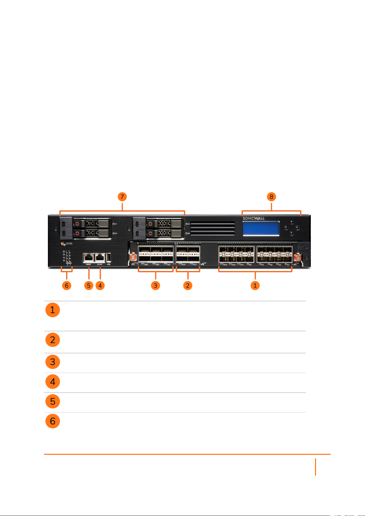
Front Panel
X0 - X15 10Gb SFP+ Ports (16)
These ports support small form-factor pluggable (SFP) modules and 10Gb Base-T
copper modules.
X16 - X19 40Gb QSFP+ Ports (4)
These 40Gb ports also support 10Gb interface connectivity.
X20 - X25 100Gb QSFP28 Ports (6)
Serial Console Port
MGMT Port – 1GbE
LED Indicators
LEDs from top: Power, Alarm, System Status, MGMT Port
SonicOSX 7 Getting Started Guide for the NSsp Series
Product Overview
7
SSD Drives – 480GB (4)
LCD Screen
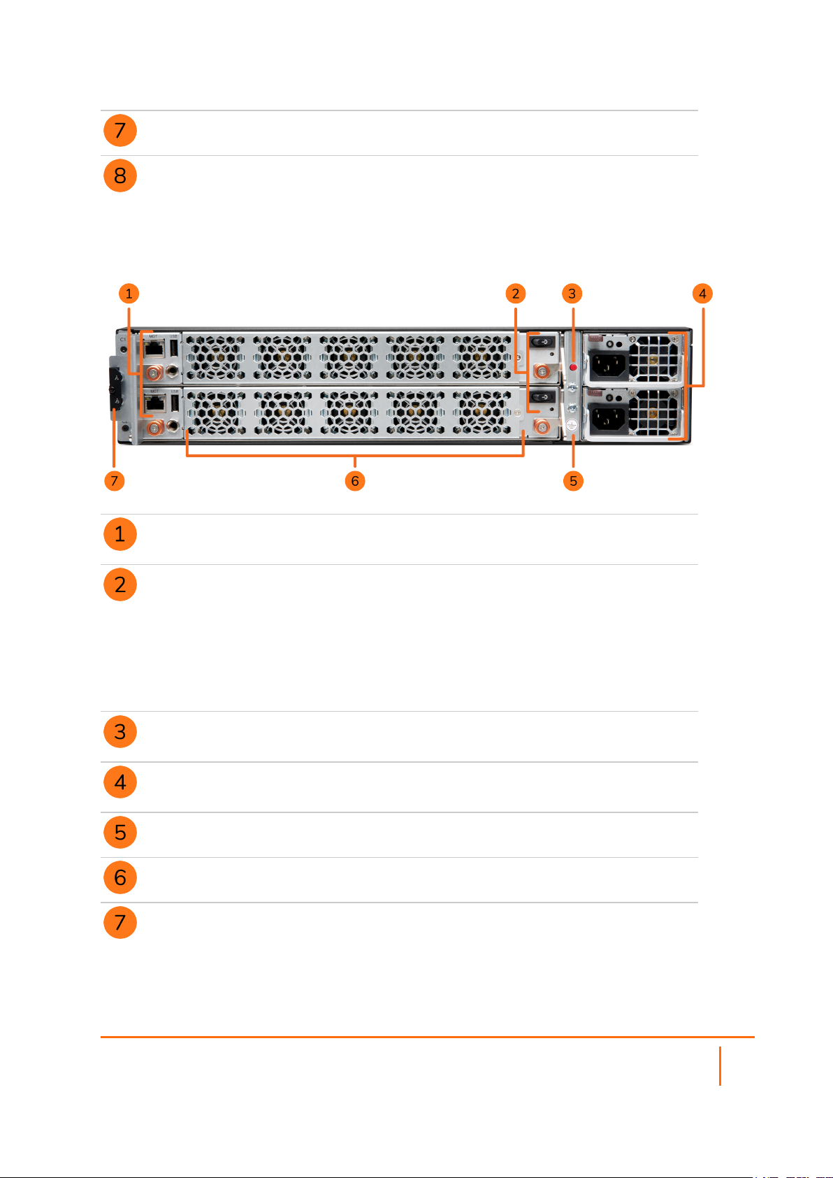
Rear Panel
AUX MGMT Ports (2) – 1GbE
Provides management access for SonicWall Technical Support
Power Switches and Status LEDs (2)
Press and release to power on
LED status:
l Off – Power is off for the compute blade
l Blinking Blue – Compute blade is in powering-up stage
l Solid Blue – Power is on and compute blade is up and ready
Power Alarm Cutoff Button
Press to stop alarm after power supply failure
Power Supplies (2) - 1200W each
Fully redundant, field replaceable
Ground
Fans (10)
Key Compartment
Contains keys to unlock SSD handles for removal/replacement
SonicOSX 7 Getting Started Guide for the NSsp Series
Product Overview
8

LEDs
LED Name LED Color Description
10Gb SFP+ Link LEDs,
X0-X15
40Gb QSFP+ Link LEDs,
X16-X19
100Gb QSFP28 Link LEDs,
X20-X25
MGMT Port Link LED Off
All Activity LEDs,
X0-X25, MGMT
Power
Alarm
System Status
Off
Solid Green
Off
Solid Green
Off
Solid Green
Solid Green
Solid Amber
Off
Blinking Green
Off
Green
Off
Green
Red
Off
No link
Link is up
No link
Link is up
No link
Link is up
No link
100Mbps
1Gbps
No traffic
Traffic present
Power is off for the compute blade
Power is on for the compute blade
No alarm activity
Minor system alarm
Major/critical system alarm (thermal, fan, etc.)
No compute blade or no power
MGMT Port
Amber
Green
Off
Blinking Amber
Compute blade is not ready
Compute blade is ready
No activity
Traffic present
Specifications
NOTE: For a list of qualified SFP+/QSFP transceivers, contact SonicWall Technical Support.
NSSP 15700 SPECIFICATIONS
Feature Detail
Number of Compute Blades 2
Number of CPUs 4
100G QSFP28 6
40G QSFP+ 4
SonicOSX 7 Getting Started Guide for the NSsp Series
9
Product Overview

Feature Detail
10G SFP+ 16
SSD in Compute Blade (1 per Blade) 240GB
Front SSDs for Blade #1 (Top) 480GB
RAID Configuration RAID 1
Front SSDs for Blade #2 (Bottom) 480GB
RAID Configuration RAID 1
Compact Flash 32GB 2
USB USB 2.0 Type A
Console RS232 RJ45
Management Port 1GbE RJ45
4056 Fan 10
Redundant Power Supplies 2
Power 1200 Watts
SonicOSX 7 Getting Started Guide for the NSsp Series
Product Overview
10

Topics:
l Default Settings
l System Startup
l SonicOS/X Basic Configuration
l Connecting LAN and WAN Interfaces
l Network Configuration
l Registration and Licensing
2
System Setup
Default Settings
Port IP Address / Login / Password
Serial number on nameplate; in initial firmware
Authentication
code
Registration code from MySonicWall.com
Maintenance key from MySonicWall.com
Console Serial port: baud rate: 115200; data: 8; parity none; stop 1; flow control; none
X0
X1 Not set by default
Management
(Blade 1)
Management
(Blade 2)
SafeMode
Available in GUI on Dashboard with system information
Login = techsupport / sonicwall-<buildnum>
10.10.10.10
192.168.168.168
192.168.168.167
https://192,168,168.168:65443
(admin; password)
1
SonicOSX 7 Getting Started Guide for the NSsp Series
System Setup
11

Port IP Address / Login / Password
MySonicWall.com register on MySonicWall.com to establish login and password
1
SafeMode is accessed through the Management (Blade 1) port which is by default 192.168.168.168.
This value may be changed in ChassisOS. For details, see Access the Console Port and Configure
IP Addresses from the CLI
NOTE: The login credentials are admin/password if SonicOS/X is unavailable; otherwise the
administrator’s SonicOS/X credentials work. See Using the SafeMode GUI.
System Startup
SonicOS/X comes up a few minutes after connecting the SonicOS/X to a power source. You can configure
your SonicOS/X from either the X0 or MGMT interface:
l HTTPS Management via X0
l HTTPS Management via MGMT Port
HTTPS Management via X0
The X0 interface can be configured as a static, transparent, or Layer 2 Bridged Mode interface.
1.
Connect your management computer to the SonicOS/X X0 interface and configure your computer
with a static IP address on the LAN subnet (default subnet: 10.10.10.0/24)
2.
In your browser, enter the default IP address https://10.10.10.10 and log in using the default
credentials:
3. Username: admin
Password: password
4.
Continue with SonicOS/X Basic Configuration.
HTTPS Management via MGMT Port
The MGMT port is a dedicated 1 Gigabit Ethernet interface for appliance management and SafeMode
access.
1.
Connect your management computer to the SonicOS/X MGMT interface and configure your
computer with a static IP address on the MGMT subnet (default subnet: 192.168.168.0/24).
2.
In your browser, enter the default IP address https://192.168.168.166 and log in using the
default credentials:
3. Username: admin
Password: password
4.
Continue with SonicOS/X Basic Configuration.
If the services are enabled, you can access SafeMode, SSH, or ping via the MGMT port. From SafeMode,
you can upgrade firmware, boot backup images and more.
SonicOSX 7 Getting Started Guide for the NSsp Series
System Setup
12

Using SafeMode
SafeMode is accessed on HTTPS port 65443. This is accessed via MGMT (Blade 1) configured in user
interface settings. The default is 192.168.168.168. Log in using the default MGMT SafeMode credentials:
l Username: admin
l Password: password
SafeMode is also accessed through the aux MGMT port. For more information on SafeMode, see Using the
SafeMode GUI.
Using CLI
From SSH, you can access the SonicOS/X command line interface (CLI) for configuration and to view logs
and settings. Log in with default SonicOS/X credentials:
l Username: admin
l Password: password
For more on using the CLI, see CLI Bring-Up.
SonicOS/X Basic Configuration
Use the following steps to complete a basic system configuration.
1.
Navigate to POLICY | Rules and Policies to create security rules for handling traffic. There are no
default rules, so no traffic can be passed until rules are created.
IMPORTANT: Without policy rules, the SonicOS/X only allows management traffic on X0 or the
MGMT port. No other traffic is allowed until policy rules are created by the administrator.
2.
Navigate to NETWORK | System > Interfaces to configure the X1 WAN interface.
l Static – Configures the appliance for a network that uses static IP addresses.
l DHCP – Configures the appliance to request IP settings from a DHCP server in the network.
WAN connectivity is needed for product registration and licensing. Be sure to configure DNS for the
WAN interface.
3.
Configure the administrator username and password.
4.
Connect the X0 interface to your LAN network and connect X1 to the Internet, as described in
Connecting LAN and WAN Interfaces.
5.
Register SonicOS/X as described in Registration and Licensing.
6.
For network configuration considerations, refer to Network Configuration.
SonicOSX 7 Getting Started Guide for the NSsp Series
System Setup
13

Connecting LAN and WAN Interfaces
After the initial setup is complete, physically connect the LAN and WAN interfaces to the network devices in
your environment for access to your networks or the Internet.
To connect the interfaces:
1.
Using a Twinax cable or a fiber SFP+ module with a fiber cable, connect the appliance LAN interface
(X0) to your local network 10G switch or device.
2.
Using a Twinax cable or a fiber SFP+ module with a fiber cable, connect the appliance WAN interface
(X1) to your Internet connection.
Network Configuration
Although the X0, X1 ...X15 front panel interfaces support up to 10Gb SFP+ operation, they may be setup for
1Gb operation.
The Root Instance for multibladed operation has reserved use of X0 through X3. Interface ports X4 and up
can be reserved for multiinstances. Note that to reach the license manager and receive a DHCP address, the
instances must have their own path to the Internet.
Each instance can support up to 8 virtual ports: X0...X7. X1 on each instance needs to connect to a front
panel port with access to a DHCP server or assign static IP address. While adding a new instance, on the
interface configuration tab, configure the instance X1 so that it is mapped to a front panel port and VLANID
that is setup with WANaccess. This is necessary for both cases (Static and Dynamic IP address
assignment).
For static IP configuration, choose an IP in the LAN network that is not in use. For example, if the DHCP
server uses a start range from 10.206.52.10 to 10.206.52.200, then use an IP below the range or above
the range, but not the Broadcast (10.206.52.255) or Gateway IP (for example, 10.206.52.100) address.
SonicOSX 7 Getting Started Guide for the NSsp Series
System Setup
14

For details on configuring management IP addresses, see Configure IP Addresses from the CLI. The X0 and
X1 ports can be configured through SonicOS/X GUI at NETWORK | System > Interface > Interface
Settings.
NOTE: SafeMode access is through the top AUX MGMT port to the Management (Blade 1) port. Refer
to the illustration in Rear Panel.
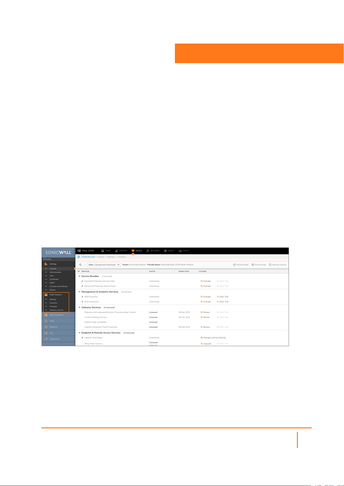
Registration and Licensing
To register SonicOS/X, you can click Register in the SonicOS/X web management interface, then enter your
MySonicWall credentials. Or you can log in to MySonicWall at https://www.mysonicwall.com from a browser
and register SonicOS/X there, then synchronize from within SonicOS/X.
Registration in MySonicWall requires your SonicOS/X serial number and authentication code, which you can
find on the appliance label or on the DEVICE | Settings > Status page of the SonicOS/X web interface.
You can purchase additional Security Service licenses by clicking Licenses in the row for your SonicOS/X on
the My Products page in MySonicWall.
Instance Licenses
When you register the SonicOS/X and license security services on it, additional license keys are
automatically created for a Multi-Instance deployment. These Instance licenses have unique serial numbers
and authentication codes. All security services licensed on the SonicOS/X are inherited by each Instance.
Each Instance license is separate and independent, allowing each Instance to have a unique configuration.
Latest Firmware
After product registration, be sure to download the latest firmware and upgrade your SonicOS/X. You can
run different SonicOS/X firmware versions on each Instance, if desired. The Instance firmware images are
available for download along with the main firmware in MySonicWall.
NOTE: Enabling Multi-Instance requires a chassis reboot, which can take up to 15 minutes.
SonicOSX 7 Getting Started Guide for the NSsp Series
System Setup
15
3
Configuring Multiple Instances
Topics:
l Enabling Multi-Instances
l Configuring Multi-Instances
l Licenses for Multiple Instances
l Deactivating an Instance
l Instance HA Pair on a Standalone NSsp Node
This feature allows the NSsp security appliance to launch multiple firewall instances, each serving as an
independent firewall. The Root Instance (RI) configures and launches each instance. After the instances are
up and running, their X0...X7 interfaces allow access for detailed network configuration.
Navigate to DEVICE | Multi-Instance to find configuration and monitoring screens.
NAVIGATING TO MULTI-INSTANCE OPTIONS
Each instances’s X0, X1, X2... X7 interfaces are mapped to a VLAN on the front panel port (X0 to X25) by the
RI. Each instance can be configured with up to eight ports. Each instance port is mapped to a front panel
port and tagged with a VLAN ID.
SonicOSX 7 Getting Started Guide for the NSsp Series
Configuring Multiple Instances
16

Enabling Multi-Instances
This feature is enabled from the Settings screen. To enable Multi-instances, we first reserve logical blades
and front panel ports that are used for supporting spawned instances.
To Enable Multiple Instances:
1.
To select the number of logical blades, click and select up to two. Click Accept to save changes. This
step requires the chassis to reboot for changes to take effect.
2.
The next step is to reserve front panel ports for instances. These ports are the ones available for
instance configuration.
3.
To select ports, click on ports that are orange. Selected ports turn green. The legend on the right of
the display provides details on the colors and the status of ports.
4.
Click Accept to save changes. This step does not require a reboot. Front panel port reservations can
be modified anytime after multiple instances are enabled.
5.
Ports reserved for the instances are green, and ports available to instances, but not yet reserved, are
orange. To reserve an orange port for instances, simply click on it to turn it green.
After Multi-Instances are enabled and logical blades are selected and ports are reserved, the reserved ports
for Multi-Instances are exclusive, that is, not available for the rest of the sub-system.
Any time Multi-Instances is disabled and the chassis is rebooted, all the Multi-Instance port(s) are
unreserved and are available to the rest of the system while all instances configured in the system are lost.
SELECTING PORTS FOR INSTANCES
Currently, a maximum of two logical blades might be configured to support instances. With four logical
blades in the system, two logical blades are used by the multi-bladed firewall while the other two can be
used for instances. However, the configuration is flexible, we could have three logical blades running in
multi-bladed firewall mode with one logical blade configured to launch instances.
SonicOSX 7 Getting Started Guide for the NSsp Series
Configuring Multiple Instances
17

ALLOCATING CPUS
The previous screen shows the Multi-Instance-enabled settings in the DEVICE | Multi-Instances >
Settings screen. In this case, four logical blades are available and one is allocated to instances, while three
support multi-bladed firewall operation.
After Multi-Instance (MI) operation is enabled on the GUI and the configuration is saved, the firewall
prompts for reboot before the settings can be applied.
NOTE: Enabling Multi-Instance requires a chassis reboot, which can take up to 15 minutes.
After the reboot firewall confirmation button is clicked, the firewall comes up with one or two logical blades
enabled for launching instances. In the left navigation column of the display, the Instances screen is
enabled only when MI is enabled. In order to change the number of logical blades selected to launch MI
instances, the firewall has to go through the reboot processes. This means the currently running instancesupport blades is also rebooted.
In order to revert back, with all the logical blades to work as one big multi-bladed firewall, the MI-enabled
settings are disabled and the firewall goes through the reboot process again.
To reserve front panel ports for virtual firewall instances:
1.
Identify available ports by looking for orange colored ports on the GUI.
2.
Click on the port to turn it green.
3.
Click Accept.
To allocate CPUs to instances:
1.
Navigate to DEVICE | Multi-Instance > Settings and locate the controls under Setup Multi-
Instance.
2.
Move the Enable switch to the right to turn on Multi-Instance capability.
3.
Determine the number of CPUs available to support instances.
4.
Click Accept and then reboot the system.
SonicOSX 7 Getting Started Guide for the NSsp Series
Configuring Multiple Instances
18

Configuring Multi-Instances
After you have MI (Multi-Instances) enabled in the RI (Root Instance), then we can configure and launch the
multiple instances. Each instance is an independent virtual firewall with its own routing table, policy
configuration, licenses and security services. Licenses of Multi-instances are inherited from the Root
Instance. Say you are using Deep Packet Inspection (DPI) and the root instance had acquired a DPI license
before adding the Multi-Instance, then the Multi-Instance does not need further operations, it already has
this license. When adding the Multi-Instance first, the root instance acquires the DPI license, and then the
Multi-Instance must be manually synchronized with the DPI license to the Root Instance by clicking Sync on
the License screen. Each instance can be configured with the required number of cores based on the use
case. Currently, we support up to eight Data Path (DP) cores maximum for each virtual firewall and two
(Control Path) CP cores per virtual firewall. Each instance virtual firewall is accessed through its DHCPenabled X1 WAN interface. The instance user interface is accessed by way of X0 as well, when an instance’s
X0 mapping is setup with an accessible static IP, gateway, subnet, is accessible to the RI front panel port,
and VLAN mapping is properly set.
Each instance virtual firewall can be accessed through its DHCP-enabled X1 WAN interface or Static X1
WAN interface.
The following figure shows the multi-instance screen with five instances added.
The Root Instance (RI) serves as the console through which all the instances are deployed. RI allows the
user to add instances, start the service, stop the service and delete the instance. Each instance added
through the Add Instance dialog is stored in the RI. This allows the user to add as many instances as
possible, however, there is a limit on the number of instances that are launched because of CPU core and
license availability.
Adding an Instance
In order to add an instance, click Multi-Instance | Instances, and then click +Add. A dialog box pops-up.
There is a limit on the number of instances that can be launched because of CPU core availability and total
Instance Licenses available in the system.
Before completing this step, upload the Instance Firmware from the Multi-Instance > Firmware page. A
typical Multi-Instance setup work flow is:
SonicOSX 7 Getting Started Guide for the NSsp Series
Configuring Multiple Instances
19

Enable Multi-Instances:
1.
Reserve Logical Blades.
2.
Reserve port(s) and reboot chassis.
3.
Register the box, if not registered, to obtain instance instances.
4.
Verify that instance licenses are available on the Multi-Instance > Instance Licenses page.
5.
Upload the Instance Firmware from the Multi-Instance > Firmware page.
6.
Add instance, or start/stop/reboot/edit/deactivate/delete instances(s).
ADD INSTANCE DIALOG BOX
In the +Add dialog, all the fields must be populated:
l Organization Name — identifies operating enterprise, a name that is a string.
l Instance Name — field requires a name that is a string. The Instance Name length can be equal to
or greater than eight characters and less than or equal to 63 characters.
l ACI Version — a drop-down menu and you must pick one of the ACI versions that need to be
running on the instance. In order to upload an ACI, follow the instructions mentioned under
Uploading Instance Firmware.
l Management Cores — only two Control Plane cores can be dedicated to a particular instance.
Select the number from the right drop-down menu.
l Data Processing Cores — allows the user to select the number of DP Cores. Limit this allocation to
eight for this release. Ideal maximum would be four.
l High Availability Instance — Sets up redundant instance: Primary (active) and Secondary
(standby).
When completed, click Next, the dialog moves to the interface mapping stage:
Setup interfaces for the instance by mapping each X0, X1, X2...X7 to a physical interface from the dropdown menu. The drop-down menu shows only those front panel ports that were reserved for instances. For
each interface, provide a unique VLAN. In setting VLAN IDs:
l VLAN should be in the range of 65 .. 4094
l For a given instance, the VLAN configured on X0 .. X7 should be unique, two or more instances of Xn
cannot have the same VLAN.
SonicOSX 7 Getting Started Guide for the NSsp Series
Configuring Multiple Instances
20

Each instance can be configured with a default X0 IP address and default X1 IP (static/DHCP).
After configuration is complete, click Next.
In order to launch the instance, click Start on the Actions drop-down menu. The instance can be stopped
using Stop and restarted using Reboot.
Editing an Instance
To change the configuration of an instance:
1.
Click the Action icon at the far right of the instance row on the Instances page.
2.
When the menu appears, choose Stop.
3.
Wait until the status of the instance changes to "Stopped." This could take up to five minutes.
4.
Click Action again and then click Edit.
STOP AND EDIT BUTTONS UNDER ACTION ON INSTANCE DISPLAY
SonicOSX 7 Getting Started Guide for the NSsp Series
Configuring Multiple Instances
21

Uploading Instance Firmware
The firmware for launching the instances has to be pre-loaded using the RI. On the DEVICE | MultiInstance > Firmware page upload the ACI file as shown.
UPLOADING INSTANCE FIRMWARE
After the file is uploaded, the firmware appears as a choice in the Add/Edit Instance dialog.
NOTE: The instance firmware is not the same as the root firewall firmware. This instance firmware is
exclusive to instances only.
After the upload is successful, the installation takes about two ~ five minutes. You should wait until the
Status column appears Inactive in the Instance firmware page.
The steps for upgrading firmware for an instance are:
To Upgrade Instance Firmware:
1.
Upload the firmware as described previously.
2.
Stop the instance.
3.
Use the edit process to select new firmware.
4.
Restart the instant.
SonicOSX 7 Getting Started Guide for the NSsp Series
Configuring Multiple Instances
22

Licenses for Multiple Instances
Topics:
l Surveying Multiple Instances
l Instance Registration
l Instance License Update
Surveying Multiple Instances
Instance licenses are required for spawning instances. The Multi-Instance licenses are fetched onto the
system after the device is registered with the license manager. The licenses are then managed by the Root
Instance for spawning instances. The root instance takes care of assigning an available instance license to
an instance after it has started.
3
The licenses are assigned to an instance and marked as in use only when the instance is started. The
license assigned to an instance remains in use until an instance is deleted. Stopping an instance does not
release its license.
After all instances are consumed, a request to start a new instance would fail owing to insufficient licenses.
The Instances page displays the list of instance licenses and their status (used/available) and also the name
of the instance (for licenses in use).
INSTANCE LISTING
SonicOSX 7 Getting Started Guide for the NSsp Series
Licensesfor Multiple Instances
23

Instance Registration
The instance, after spawned, automatically registers itself with the license manager upon boot-up. In order
for this to work correctly, the VLAN for the instance’s X1 (WAN interface) should be configured properly so
that it has access to the WAN/Internet to reach the license manager over the network. That is, the X1
interface of the instance must be linked to a front panel port that has access to the WAN/Internet.
For more information on setting up a WAN Internet connection for instances, see "Network Configuration."
Instance License Update
When a customer has purchased additional instances, the licenses can be updated or upgraded by reregistering the device with the license manager. The Multi-Instance licenses are always designed to be a
bundle of previous + new licenses. After licenses are updated, the Root Instance identifies the newer set of
licenses and updates the licenses shown as available on the Instance page.
Deactivating an Instance
Deactivating an instance strips off the instance with all its resources (instance license, physical and logical
resources) and renders it into Inactive status.
Instance HA Pair on a Standalone NSsp Node
Multiple instances within an NSsp can support stateful HA. This multi-instance HA model exactly mimics the
NSv HA model in terms of the behavior and capabilities. Two instances can be paired to form a stateful HA.
One of them resumes the role as a Primary active instance and the other as Secondary standby instance.
The active and standby roles can change during an instance's lifetime.
This section explains how to form instance HA pairing within one NSsp.
SonicOSX 7 Getting Started Guide for the NSsp Series
Licensesfor Multiple Instances
24

HA INSTANCES WITHIN AN NSSP 15700
Prerequisites for HA Pairing of Instances within a Standalone NSsp 15700:
l Upload instance firmware.
l At least two Instance Licenses should be Available. Verify this from the Instance Licenses page.
To create a basic HA pair of instances on a standalone NSsp 15700:
1.
Add two instances.
a.
First navigate to DEVICE | Multi-Instance > Instances and check under RESOURCE
ALLOCATION that at least four CPUs are available to support Control and Data planes on two
instances.
b.
Navigate to DEVICE | Multi-Instance > Licenses and check that at least two licenses are
available.
c.
Navigate to DEVICE | Multi-Instance > Firmware and check that up-to-date firmware is
available. If not, upload new firmware. See Uploading Instance Firmware.
d.
Navigate to DEVICE | Multi-Instance > Instances and click +Add. The Add Instance
dialog appears.
SonicOSX 7 Getting Started Guide for the NSsp Series
Licensesfor Multiple Instances
25

ADD INSTANCE DIALOG
e.
Fill in Organization Name and Instance Name. Use designations that help link the pairs.
f.
Choose the ACI Version from the drop-down menu. This firmware must be the same for both
instances.
g.
Select the number of Management (control plane) and Processing (data plane) cores.
Unless the appliance itself is part of a high-availability pair, the Instance Host is grayed out
as This Firewall.
h.
Enable High Availability Instances.
i.
Click Next. The Interface Mapping step now appears.
INTERFACE MAPPING
j.
Add two ports for HA control and HA data link.
k.
Add additional ports to connect the instances to front panel ports.
NOTE: The VLAN should be in the range of 65 .. 4094.
l.
Click Next and the Advanced Settings dialog box appears.
SonicOSX 7 Getting Started Guide for the NSsp Series
26
Licensesfor Multiple Instances

ADVANCED SETTINGS
m.
Configure the settings. Those shown above are typical for instances supporting HA.
NOTE: Configure default X0 and X1 static IP for the HA instances. X0 and X1 are virtual
IP addresses for the HA instances.
n.
Click Next and the HA Settings dialog box appears.
HA SETTINGS
o.
Copy available instance serial numbers from the Instance Licenses page, one for the
Primary and one for the secondary Instance.
p.
Assign Control and Data interfaces between the two instances.
q.
Make a note of the LAN and WAN monitor IP addresses for the HA instances, derived from
the default X0 and X1 IP.
r.
Note Reside Information and LAN / WAN monitor IP addresses.
s.
Click Next and the Summary appears.
SonicOSX 7 Getting Started Guide for the NSsp Series
Licensesfor Multiple Instances
27

SUMMARY
2.
Navigate to DEVICES | Multi-Instance > Instances.
START INSTANCES
3.
After the instances are RUNNING, log in to the instance’s user interface.
4.
After the HA instances have started, one instance is elected as Primary Active, and the other reboots
and come up as Secondary Standby.
5.
After the HA pairing is successful, the Root Instance displays the HA status and HA peer information
along with other instance information.
6.
The instance HA status can also be verified by logging into the instance user interface and navigating
to the DEVICE | High Availability > Monitoring.
SonicOSX 7 Getting Started Guide for the NSsp Series
Licensesfor Multiple Instances
28

Configuring High Availability
Topics:
l High Availability Overview
l Setting Up Unit-to-Unit HA
l Configuring Advanced Settings
l Checking High Availability Status
l Monitoring High Availability
l Configuring Multi-Appliance Instance-Level HA
4
High Availability Overview
There are three forms of HA supported by the NSsp 15700:
The NSsp 15700 supports three kinds of High Availability:
l HA Instances with an NSsp 15700— Instances on one NSsp form high availability pairs. See Instance
HA Pair on a Standalone NSsp Node.
l Multi-appliance instance-level HA — Instances on different NSsp 15700 appliances form HA pairs.
But not all instances are duplicated on both appliances. See Configuring Multi-Appliance Instance-
Level HA.
l Appliance-level HA — One appliance fully duplicates another instance. This configuration is
described in the sections that follow.
NOTE: Licenses must be in place at both instance and appliance level to support HA.
Setting Up Unit-to-Unit HA
This section provides instructions for setting Active/Standby HA between two NSsp appliances.
Prerequisites
l Both Primary and Secondary units must be Internet addressable and inter-accessible.
l The Root Instance versions on each unit must be identical.
SonicOSX 7 Getting Started Guide for the NSsp Series
Configuring High Availability
29

l The composition of the Root Instances on each unit must be the same in terms of the numbers of
control and data plane cores.
To configure Active Standby HA:
1.
Log into the Primary appliance and navigate as shown to DEVICE | High Availability > Settings.
The following display appears.
2.
For Mode, select Active/Standby.
With Enable Preempt Mode off, select Enable Stateful Synchronization. This option is not
selected by default.
When Stateful High Availability is not enabled, session state is not synchronized between the Primary
and Secondary firewalls. If a failover occurs, any session that had been active at the time of failover
needs to be renegotiated.
3.
Select Enable Preempt Mode. This feature controls the behavior in which the Primary unit seizes
the Active role from the Backup after it recovers from an error condition, reboots or firmware
upgrades, after it successfully communicates to the backup unit that it is in a verified operational
state.
4.
Select Enable Virtual MAC to allow the Primary and Secondary firewalls to share a single MAC
address.
This greatly simplifies the process of updating network ARP tables and caches when a failover
occurs. This option is not selected by default.
5.
Selecting Enable Encryption for Control Communication is recommended when the HA units
are not co-located.
6.
Under HA Devices, enter the Secondary firewall serial number. The serial number for the Primary is
dimmed out and cannot be changed.
7.
Under HA Interfaces, select the interface for the HA Control Interface. This option is dimmed and
the interface displayed if the firewall detects that the interface is already configured.
8.
Select the interface for the HA Data Interface. This option is dimmed and the interface displayed out
if the firewall detects that the interface is already configured.
9.
When finished with all High Availability configuration, click ACCEPT. All settings are synchronized to
the Secondary firewall, and the Secondary firewall reboots.
SonicOSX 7 Getting Started Guide for the NSsp Series
Configuring High Availability
30

Configuring Advanced Settings
To configure advanced settings:
1.
Navigate to DEVICE | High Availability > Advanced.
2.
Adjust the Heartbeat Interval to control how often the security appliances in the Active/Standby pair
communicate. The default is 1,000 milliseconds (one second), the minimum value is 1,000
milliseconds, and the maximum is 300,000. A heartbeat interval of at least 1000 is recommended.
3.
Set the Failover Trigger Level to the number of heartbeats that can be missed before failing over.
The default is five, the minimum is four, and the maximum is 99.
This timer is linked to the Heartbeat Interval timer. If the Failover Trigger Level is set to five and
the Heartbeat Interval is set to 10000 milliseconds (10 seconds), it takes 50 seconds without a
heartbeat before a failover is triggered.
4.
Set the Probe Interval to the interval, in seconds, between probes sent to specified IP addresses to
monitor that the network critical path is still reachable. This interval is used in logical monitoring for
the local HA pair. The default is 20 seconds, and the allowed range is five to 255 seconds.
A probe interval of at least five seconds is recommended.
5.
Set the Probe Count to the number of consecutive probes before SonicOSX concludes that the
network critical path is unavailable or the probe target is unreachable. This count is used in logical
monitoring for the local HA pair. The default is three, and the allowed range is three to 10.
6.
Set the Election Delay Time to the number of seconds the Primary security appliance waits to
consider an interface up and stable. The default is three seconds, the minimum is three seconds, and
the maximum is 255 seconds.
7.
Set the Dynamic Route Hold-Down Time to the number of seconds the newly-active security
appliance keeps the dynamic routes it had previously learned in its route table. The default value is
45 seconds, the minimum is 1 second, and the maximum is 1200 seconds (20 minutes).
In large or complex networks, a larger value might improve network stability during a failover.
8.
If you want Failover to occur only when ALL aggregate links are down, select Active/Standby
Failover only when ALL aggregate links are down. This option is not selected by default.
SonicOSX 7 Getting Started Guide for the NSsp Series
Configuring High Availability
31

9.
To have the appliances synchronize all certificates and keys within the HA pair. select Include
Certificates/Keys. This option is selected by default.
10.
(Optional) To synchronize the SonicOSX preference settings between your primary and secondary
HA firewalls, click SYNCHRONIZE SETTINGS.
11.
(Optional) To synchronize the firmware version between your primary and secondary HA firewalls,
click SYNCHRONIZE FIRMWARE.
12.
(Optional) To test the HA failover functionality is working properly by attempting an Active/Standby
HA failover to the secondary security appliance, click FORCE ACTIVE/STANDBY FAILOVER.
13.
When finished with all High Availability configuration, click ACCEPT. All settings are synchronized to
the secondary NSsp.
Checking High Availability Status
This screen summarizes the status of the high availability pair.
HIGH AVAILABILITY STATUS
High Availability Status
l Status — Indicates Primary or Secondary and ACTIVE or STANDBY.
l Primary State — Initial configuration.
l Secondary State — Secondary configuration.
l Active Up Time — Indicates how long the current Active firewall has been Active, since it last
became Active. This line only displays when High Availability is enabled. If failure of the Primary
SonicWall occurs, the Secondary SonicWall assumes the Primary SonicWall LAN and WAN IP
addresses.
SonicOSX 7 Getting Started Guide for the NSsp Series
Configuring High Availability
32

l Found Peer — Indicates if the Primary unit has discovered the Secondary unit. Possible values are
Yes and No.
l Settings Synchronized — Indicates if HA settings are synchronized between the Primary and
Secondary units. Possible values are Yes and No.
l Stateful HA Synchronized — Indicates if stateful synchronization settings are synchronized
between the Primary and Secondary units. Possible values are Yes and No.
High Availability Configuration
l HA Mode — One method to determine which SonicWall instance is Active is to check the HA
Settings Status indicator on the DEVICE | High Availability > Settings page. If the Primary
SonicWall is Active, the first line in the page indicates that the Primary SonicWall is currently Active.
It is also possible to check the status of the Secondary SonicWall by logging into the independent
LAN management IP addresses of the Secondary SonicWall. If the Primary SonicWall is operating
normally, the status indicates that the Secondary SonicWall is currently Standby. If the Secondary
has taken over for the Primary, the status indicates that the Secondary is currently Active. In the
event of a failure in the Primary SonicWall, you can access the management interface of the
Secondary SonicWall at the Primary SonicWall LAN IP address or at the Secondary SonicWall LAN IP
address. When the Primary SonicWall restarts after a failure, it is accessible using the third IP
address created during configuration. If preempt mode is enabled, the Primary SonicWall becomes
the Active firewall and the Secondary firewall returns to Standby status.
l Control Link — Indicates the port, speed, and duplex settings of the HA link, such as HA 1000
Mbps full-duplex, when two firewalls are connected over their specified HA interfaces. When High
Availability is not enabled, the field displays Not Configured.
l Data Link — Indicates the port, speed, and duplex settings of the HA link, such as HA 1000 Mbps
full-duplex, when two firewalls are connected over their specified HA interfaces. When High
Availability is not enabled, the field displays Not Configured.
High Availability Licenses
l Primary Stateful HA Licensed — Indicates if the Primary appliance has a stateful HA license.
Possible values are Yes or No.
l Secondary Stateful HA Licensed — Indicates if the Secondary appliance has a stateful HA
license. Possible values are Yes or No. The Stateful HA license needs to be activated on both the
primary and secondary firewalls separately, they are not shared. You must access MySonicWall.com
while logged into the LAN management IP address of the Secondary unit in order to synchronize with
the SonicWall licensing server.
Monitoring High Availability
The monitoring display enables the ports on both firewall instances to be continuously checked for
performance. To do this, a probe port is defined for each port.
HA Mode - One method to determine which SonicWall is Active is to check the HA Settings Status indicator
on the DEVICE | High Availability > Settings page. If the Primary SonicWall is Active, the first line in the
SonicOSX 7 Getting Started Guide for the NSsp Series
Configuring High Availability
33

page indicates that the Primary SonicWall is currently Active. It is also possible to check the status of the
Secondary SonicWall by logging into the LAN IP address of the Secondary SonicWall.
MONITORING DISPLAY
To set the independent LAN management IP addresses and configure physical and/or logical
interface monitoring:
1.
Login as an administrator to the Primary SonicWall appliance.
2.
Navigate to DEVICE | High Availability > Monitoring.
3.
Click the Configure icon for an interface on the LAN, such as X0. The Edit HA Monitoring dialog
box displays.
4.
To enable link detection between the designated HA interfaces on the Primary and Secondary units,
leave Physical Interface Monitoring enabled. This option is selected by default on only X0 (default
LAN) and X1 (default WAN).
5.
In the Primary IPv4/v6 Address field, enter the unique LAN management IP address of the Primary
unit. The default is 0.0.0.0.
6.
In the Secondary IPv4/v6 Address field, enter the unique LAN management IP address of the
Secondary unit. The default is 0.0.0.0.
7.
Select Allow Management on Primary/Secondary IP Address. When this option is enabled for
an interface, a green icon appears in the interface’s Management column in the Monitoring Settings
table. Management is only allowed on an interface when this option is enabled. This option is not
selected by default.
8.
In the Logical Probe IPv4/v6 Address field, enter the IP address of a downstream device on the
LAN network that should be monitored for connectivity. Typically, this should be a downstream router
or server. (If probing is desired on the WAN side, an upstream device should be used.) This option is
not selected by default.
SonicOSX 7 Getting Started Guide for the NSsp Series
Configuring High Availability
34

The Primary and Secondary security appliances regularly ping this probe IP address. If both
successfully ping the target, no failover occurs. If neither successfully ping the target, no failover
occurs, because it is assumed that the problem is with the target, and not the security appliances.
But, if one security appliance can ping the target but the other cannot, failover occurs to the security
appliance that can ping the target.
The Primary IPv4/v6 Address and Secondary IPv4/v6 Address fields must be configured with
independent IP addresses on a LAN interface, such as X0, (or a WAN interface, such as X1, for
probing on the WAN) to allow logical probing to function correctly.
9.
Optionally, to manually specify the virtual MAC address for the interface, select Override Virtual
MAC and enter the MAC address in the field. The format for the MAC address is six pairs of
hexadecimal numbers separated by colons, such as A1:B2:C3:d4:e5:f6. This option is not selected
by default.
IMPORTANT: Care must be taken when choosing the Virtual MAC address to prevent
configuration errors.
When Enable Virtual MAC is selected on DEVICE | High Availability > Advanced Settings, the
SonicOSX firmware automatically generates a Virtual MAC address for all interfaces. Allowing the
SonicOSX firmware to generate the Virtual MAC address eliminates the possibility of configuration
errors and ensures the uniqueness of the Virtual MAC address, which prevents possible conflicts.
10.
Click OK.
11.
To configure monitoring on any of the other interfaces, repeat Step 3 through Step 10 for each
interface.
12.
When finished with all High Availability configuration, click ACCEPT. All settings are synchronized to
the Secondary unit automatically.
Configuring Multi-Appliance Instance-Level HA
This configuration assumes an established appliance-to-appliance HA pairing as described in Setting Up
Unit-to-Unit HA.
To establish an HA pair of instances residing on different NSsp appliances:
1.
First establish unit-to-unit pairing as described in Setting Up Unit-to-Unit HA.
2.
Have at least one dedicated unused physical port connected on both the NSsp HA unit, to be used for
the Multi-instances HA control interface and HA Data interface. Although we recommend two
dedicated unused ports, one for the HA control interface and one for the HA data interface.
3.
Upload instance firmware on both primary and secondary appliances. After the firmware is uploaded
successfully on both the primary and secondary units verify that the Running column on the DEVICE |
Instance > Firmware page on the Active unit shows as BOTH.
SonicOSX 7 Getting Started Guide for the NSsp Series
Configuring High Availability
35

INSTANCE > FIRMWARE PAGE
4.
Ensure that both Primary and Secondary Instances are Registered with MySonicWall.com and both
units have Instance Licenses from their respective Instance License page.
5.
Repeat Step a to Step s for adding virtual instance HA pair on ACTIVE NSsp appliance as mentioned
the Instance HA pair on a standalone NSsp. Refer to Instance HA Pair on a Standalone NSsp Node.
Ensure that Primary Instance License is selected from the Primary NSsp Instance License page, and
Secondary Instance License is selected from the Secondary NSsp Instance License page.
6.
Note that the residence of the instance is announced in the following figure, Residence
Announcement.
RESIDENCE ANNOUNCEMENT
7.
Verify the addition of a Primary and a Secondary Instance from the Multi-Instance on the Instances
page.
SonicOSX 7 Getting Started Guide for the NSsp Series
Configuring High Availability
36

Topics:
l Access the Console Port
l At the ChassisOS Prompt
l To Change to the Console Port of Another Physical Blade
l Check Network Address Settings
l Commands at ChassisOS Prompt
l Show Commands at ChassisOSPrompt
l Configure IP Addresses from the CLI
l Restart SonicOS from the CLI
l To Access SonicOSConsole
5
CLI Bring-up
Access the Console Port
For location of the physical port, refer to the Front Panel.
Serial port: baud rate: 115200; data: 8; parity none; stop 1; flow control; none
Login = techsupport; password = sonicwall-3813
The SonicCore banner appears and the login takes you to the ChassisOS prompt. See Logging into
ChassisOS through the Console Port.
If the SonicCore banner does not come up and offer a login, check to ensure the NSsp has completed its
boot up process.
SonicOSX 7 Getting Started Guide for the NSsp Series
CLI Bring-up
37

LOGGING INTO CHASSISOS THROUGH THE CONSOLE PORT
To logout of ChassisOS, simply enter quit.
At the ChassisOS Prompt
The ChassisOS-1 prompt indicates you are logged into physical blade 1 in the system. From here you can
move to the second physical blade, ChassisOS-2.
To get a brief help summary, enter ?.
CHASSIS OS HELP
SonicOSX 7 Getting Started Guide for the NSsp Series
CLI Bring-up
38

To Change to the Console Port of Another Physical Blade
Use switch-serial-port and indicate the port to which you are moving.
Use the same login and password information after the SonicCore banner.
CHANGING PHYSICAL BLADES
SonicOSX 7 Getting Started Guide for the NSsp Series
CLI Bring-up
39

Check Network Address Settings
At the ChassisOS prompt, enter: show network.
CHECKING IP ADDRESS
The first three IP addresses in the above listing are for the NSsp Management port.
So from the Management port, you can connect to Blade 1, Blade 2, and SonicOSX.
The two aux chassis IP ports support access to the two blade platforms from rear panel RJ45 interface
connectors.
Commands at ChassisOS Prompt
A list of common commands appears in response to ?.
CHASSISOS COMMANDS
SonicOSX 7 Getting Started Guide for the NSsp Series
CLI Bring-up
40

The commands include:
l ping allows pinging of addresses in the Management network
l shell initiates the system shell
l install-failsafe securely installs a failsafe image between a local host and a remote host or
between two remote hosts.
l power-cycle turns power to the physical blades on and off and effects a reset of SonicOSX and all
instances
l reboot-system restarts all software (relatively graceful)
l restart sonicOS restarts only SonicOSX instances
l scp-core-dump in the event of a system crash, this allows a secure copy of a core dump to a
Management network address
Show Commands at ChassisOSPrompt
Enter show ? to get a list:
SHOW OS COMMANDS
l show console-logs: Shows logs of individual logical blades, allows stepping through logs of all four
logical blades. These are SonicOSX console logs.
l show core-dump-files: Show all of the core dump files that have been generated so far.
l show env-sensors: Lists BMC parameters tracking temperature, fan speed, and so on.
l show mt-status: Shows allocation of CPU cores on specified CPU (1 to 4) among the two Logical
Blades. This command only works on the master blade (Physical Blade 1).
l show system-status: This command is particularly useful in showing processes in progress on the
two Physical Blades:
SonicOSX 7 Getting Started Guide for the NSsp Series
CLI Bring-up
41

SHOW SYSTEM STATUS COMMAND
A useful installation routine for administrators would be to first check system hardware indications with show
env-sensors:
SonicOSX 7 Getting Started Guide for the NSsp Series
CLI Bring-up
42

SHOW ENV-SENSORS
Then check SonicOSX with show sonicos-status:
SHOW SONIOCS- STATUS
SonicOSX 7 Getting Started Guide for the NSsp Series
CLI Bring-up
43

Configure IP Addresses from the CLI
Move back and forth to Configure Mode using configure and exit.
CONFIGURE IP ADDRESSES
For a list of Configuration Mode commands, enter ?.
Of these, the most useful is network-mgmt. This allows changing the SonicOSX management, blade
management and gateway IPaddresses to conform to your network. Example syntax:
network mgmt IPv4 sonicos-IP 192.168.169.33 netmask 255.255.255.0 chassis-IP
192.168.169.3.
In the previous line, the TAB key can be used to generate the works identifying the IPaddresses, while the
addresses must be provided. All of the address are changed at once in this manner.
Immediately after reconfiguring management IPaddresses, the services-mgmt command allows setting
up safemode, ping, or ssh services, or all three.
Restart SonicOSX from the CLI
SonicOSX can be rebooted from current settings:
restart-sonicos
Or from factory defaults:
restart-sonicos factory-settings true
CAUTION: Returning to factory defaults could disrupt your testing efforts as current settings
are lost.
To Access SonicOSX Console
Entering smconsole 1 allows access to the SonicOSX Console CLI on the Root Instance.
To gain access to the console use admin and password. Enter ? for help.
SonicOSX 7 Getting Started Guide for the NSsp Series
CLI Bring-up
44

ACCESSING THE SONICOSX CONSOLE
A useful operation at the SonicOSX Console is show interfaces. This gives an overview of the firewall's
status. Type Ctrl-C or quit to end.
SonicOSX 7 Getting Started Guide for the NSsp Series
CLI Bring-up
45

Using the SafeMode GUI
From the SafeMode GUI, you can upgrade firmware, boot backup images and check the status of the
hardware.
NOTE: Unlike SafeMode on other SonicWall appliances, SafeMode is not a state in the NSsp; instead it
is a GUI available at all times. The appliance does not need to go into the SafeMode state in order to
access the SafeMode utilities.
Topics:
l Accessing SafeMode
l Rebooting the System
l Upgrading Firmware
l Diagnostics
6
Accessing SafeMode
AUX MGMT 1 Port
Access SafeMode at the management port for Blade 1 on the rear panel of the NSsp chassis. This requires a
cable to the top Aux MGMT port shown in the rear panel photograph see Rear Panel.
IP Address
Access SafeMode at the management port for Blade 1 on the rear panel of the NSsp chassis. This requires a
cable to the top Aux MGMT port shown in the rear panel photograph; see Rear Panel. To find the IP
Address, see Check Network Address Settings. Use this IP address with https://aux chasis ip
(B1):65443.
Login Credentials
When SonicOSX is running, only credentials with full configuration privileges allows access. If SonicOSX is
down, the Maintenance Key available for the product from www.MySonicWall.com, must be used.
SonicOSX 7 Getting Started Guide for the NSsp Series
Using the SafeMode GUI
46

Rebooting the System
Upon login, the SafeMode GUI opens to Firmware Management. The Restart System item is to the upper
right.
REBOOTING THE SYSTEM
Upgrading Firmware
To upload new firmware:
1.
Click Upload Firmware and locate new firmware. Firmware upgrades are available through
www.MySonicWall.com.
UPLOADING FIRMWARE
2.
Having downloaded an image from MySonicWall to your PC, upload using the dialog. The image
then appears in the table of Firmware Images. From there, you can choose to install it using the
current configuration or opt to use the default settings.
To boot new firmware:
1.
Select the option as shown below and boot.
The upload and boot process takes only about two minutes.
SonicOSX 7 Getting Started Guide for the NSsp Series
Using the SafeMode GUI
47

BOOT FIRMWARE
Diagnostics
Four tabs within the Diagnostics section provide information on the system and its current state.
System Information
This tab presents basic information on the NSsp 15700.
SYSTEM INFORMATION
Hardware Sensors
This tab lists hardware sensors in the NSsp 15700.
This is also accessible through the CLI. See Show Commands at ChassisOSPrompt.
Switch Port Counters
This tab presents details on the switching performance of the 26 ports on the NSsp 15700 front panel.
SonicOSX 7 Getting Started Guide for the NSsp Series
Using the SafeMode GUI
48

SWITCH PORT COUNTER TAB
Switch Port SFP Information
This tab provides details on the SFP links used on the NSsp 15700.
SWITCH PORT SFP INFORMATION
SonicOSX 7 Getting Started Guide for the NSsp Series
Using the SafeMode GUI
49

SonicWall Support
Technical support is available to customers who have purchased SonicWall products with a valid
maintenance contract.
The Support Portal provides self-help tools you can use to solve problems quickly and independently, 24
hours a day, 365 days a year. To access the Support Portal, go to https://www.sonicwall.com/support.
The Support Portal enables you to:
l View knowledge base articles and technical documentation
l View and participate in the Community forum discussions at
https://community.sonicwall.com/technology-and-support.
l View video tutorials
l Access https://mysonicwall.com
l Learn about SonicWall professional services
l Review SonicWall Support services and warranty information
l Register for training and certification
l Request technical support or customer service
7
To contact SonicWall Support, visit https://www.sonicwall.com/support/contact-support.
SonicOSX 7 Getting Started Guide for the NSsp Series
50
SonicWall Support

About This Document
NOTE: A NOTE icon indicates supporting information.
IMPORTANT: An IMPORTANT icon indicates supporting information.
TIP: A TIP icon indicates helpful information.
CAUTION: A CAUTION icon indicates potential damage to hardware or loss of data if
instructions are not followed.
WARNING: A WARNING icon indicates a potential for property damage, personal injury, or
death.
SonicOSX Getting Started Guide for the NSsp Series
Updated - April2021
Software Version - 7
232-005469-00 Rev B
Copyright © 2021 SonicWall Inc. Allrights reserved.
The information in thisdocument is provided in connection with SonicWall and/or its affiliates’ products. No license, express or
implied, by estoppel or otherwise, to any intellectual property right is granted by this document or in connection with the sale of
products. EXCEPT AS SET FORTH IN THE TERMS AND CONDITIONS AS SPECIFIED IN THE LICENSE AGREEMENT FOR
THIS PRODUCT, SONICWALL AND/OR ITS AFFILIATES ASSUME NO LIABILIT Y WHATSOEVER AND DISCLAIMS ANY
EXPRESS, IMPLIED OR STATUTORY WARRANTY RELATING TO ITS PRODUCTS INCLUDING, BUT NOT LIMITED TO,
THE IMPLIED WARRANTY OF MERCHANTABILITY, FITNESS FOR A PART ICULAR PURPOSE, OR NON-INFRINGEMENT.
IN NO EVENT SHALL SONICWALL AND/OR ITS AFFILIATES BE LIABLE FOR ANY DIRECT, INDIRECT , CONSEQUENTIAL,
PUNITIVE, SPECIAL OR INCIDENTAL DAMAGES (INCLUDING, WITHOUT LIMITATION, DAMAGES FOR LOSS OF
PROFITS, BUSINESS INTERRUPTION OR LOSS OF INFORMATION) ARISING OUT OF THE USE OR INABILITY TO USE
THIS DOCUMENT, EVEN IF SONICWALL AND/OR ITS AFFILIATES HAVE BEEN ADVISED OF THE POSSIBILITY OF SUCH
DAMAGES. SonicWall and/or its affiliates make no representations or warranties with respect to the accuracy or completeness of
the contents of this document and reserves the right to make changes to specifications and product descriptions at any time without
notice. and/or its affiliates do not make any commitment to update the information contained in this document.
For more information, visit https://www.sonicwall.com/legal.
End User Product Agreement
To view the SonicWall End User Product Agreement, go to: https://www.sonicwall.com/legal/end-user-product-agreements/.
Open Source Code
SonicWall Inc. is able to provide a machine-readable copyof open source code with restrictive licensessuch as GPL, LGPL, AGPL
when applicableper licenserequirements. To obtain a complete machine-readable copy, send your written requests, along with
certified check or money order in the amount of USD 25.00 payable to “SonicWall Inc.”, to:
General Public License Sour ce Code Request
Attn: Jennifer Anderson
1033 McCarthy Blvd
Milpitas, CA 95035
SonicOSX 7 Getting Started Guide for the NSsp Series
SonicWall Support
51
 Loading...