


SonicOSX 7
Rules and Policies
Administration Guide

Contents
Settings 5
Configuring App/Match/Malware 6
Settings: Application, Custom Match and Malware Prevention Settings 6
Application Cache 6
Security Services Settings 7
Configuring Content Filtering Service (CFS) 8
SonicWall CFS 8
CFS Custom Category 9
Geo-IP 10
Policy-based Settings 10
Global Settings 10
Custom List 10
Using Geo-IP Diagnostics 11
Botnet 12
Configuring Botnet Settings 12
Creating Custom Botnet Lists 13
Viewing Dynamic Botnets Lists 15
Configuring a Dynamic Botnet List Server 15
Using Botnet Diagnostics 16
Decryption (DPI-SSL) 17
SSL Client Inspection 17
SSL Server Inspection 18
Certificate 18
Common Name 18
SSL Servers 19
Decryption (DPI-SSH) 19
Signature Update 20
Security Policy 21
App/URL/Custom Match 23
Action Profile 24
NAT Policy 25
About NAT in SonicOSX 25
About NAT Load Balancing 26
Determining the NAT LB Method to Use 27
Caveats 27
How Load Balancing Algorithms are Applied 28
Sticky IP Algorithm Examples 28
About NAT64 29
SonicOSX 7 Rules and Policies Administration Guide
Contents
2

Use of Pref64::/n 29
About FQDN-based NAT 30
About Source MAC Address Override 30
Viewing NAT Policy Entries 30
Changing the Display 31
Filtering the Display 31
Adding or Editing NAT or NAT64 Policies 31
Deleting NAT Policies 36
Creating NAT Rule Policies: Examples 36
Creating a One-to-One NAT Policy for Inbound Traffic 37
Creating a One-to-One NAT Policy for Outbound Traffic 39
Inbound Port Address Translation via One-to-One NAT Policy 41
Inbound Port Address Translation via WAN IP Address 44
Creating a Many-to-One NAT Policy 47
Creating a Many-to-Many NAT Policy 49
Creating a One-to-Many NAT Load Balancing Policy 52
Creating a NAT Load Balancing Policy for Two Web Servers 55
Creating a WAN-to-WAN Security Policy for a NAT64 59
DNS Doctoring 61
Routing Rules 63
About Routing 63
About Metrics and Administrative Distance 64
Route Advertisement 65
ECMP Routing 66
Policy-based Routing 66
Policy-based TOS Routing 66
PBR Metric-based Priority 67
Policy-based Routing and IPv6 68
OSPF and RIP Advanced Routing Services 68
Drop Tunnel Interface 77
App-based Routing 77
Rules and Policies > Routing Rules 78
Configuring Routing Rules 78
Decryption Policy 81
Behavior 81
Decryption Policy Types 81
Client-side SSL Rules 81
Server-side SSL Rules 82
SSH Rules 82
Setting up the Decryption Policy Table 82
Managing the Decryption Policy Toolbars 85
Changing the Policy Priority 86
Creating Decryption Policies 86
SonicOSX 7 Rules and Policies Administration Guide
Contents
3

DoS Policy 89
Setting up the DoS Policy Table 89
Managing the DoS Policy Toolbars 92
Changing the DoS Policy Priority 93
Creating DoS Policies 93
Endpoint Policy 96
Adding a Policy 96
Shadow 98
SonicWall Support 100
About This Document 101
SonicOSX 7 Rules and Policies Administration Guide
Contents
4
1
Settings
NOTE: References to SonicOS/X indicate that the functionality is available in both SonicOS and
SonicOSX.
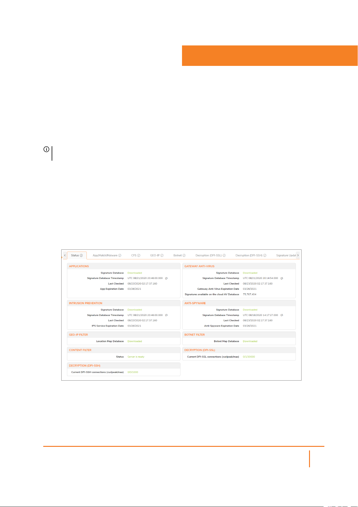
The Settings page is an all-inclusive, unified policy configuration dashboard that combines Layer 2 to Layer
7 policy enforcement. The Settings page shows the licensed security services available within your system.
From this page you are able to track service statuses, expiration dates, signature timestamps, and last time
those service were checked. The Status tab displays the current status of your Security Service features.
You can also update your services by clicking the Update icon at the end of the Signature Database
Timestamp entry.
To view the Policy Settings page:
1.
Navigate to POLICY | Rules and Policies > Settings.
The Settings | Status page displays.
2.
Check that services are correctly licensed, updated, and functioning correctly.
You can click the tabs at the top of the page to further configure your services:
l App/Match/Malware
l Configuring Content Filtering Service (CFS)
l Geo-IP
SonicOSX 7 Rules and Policies Administration Guide
5
Settings
l Botnet
l Decryption (DPI-SSL)
l Decryption (DPI-SSH)
l DoS
l Licenses
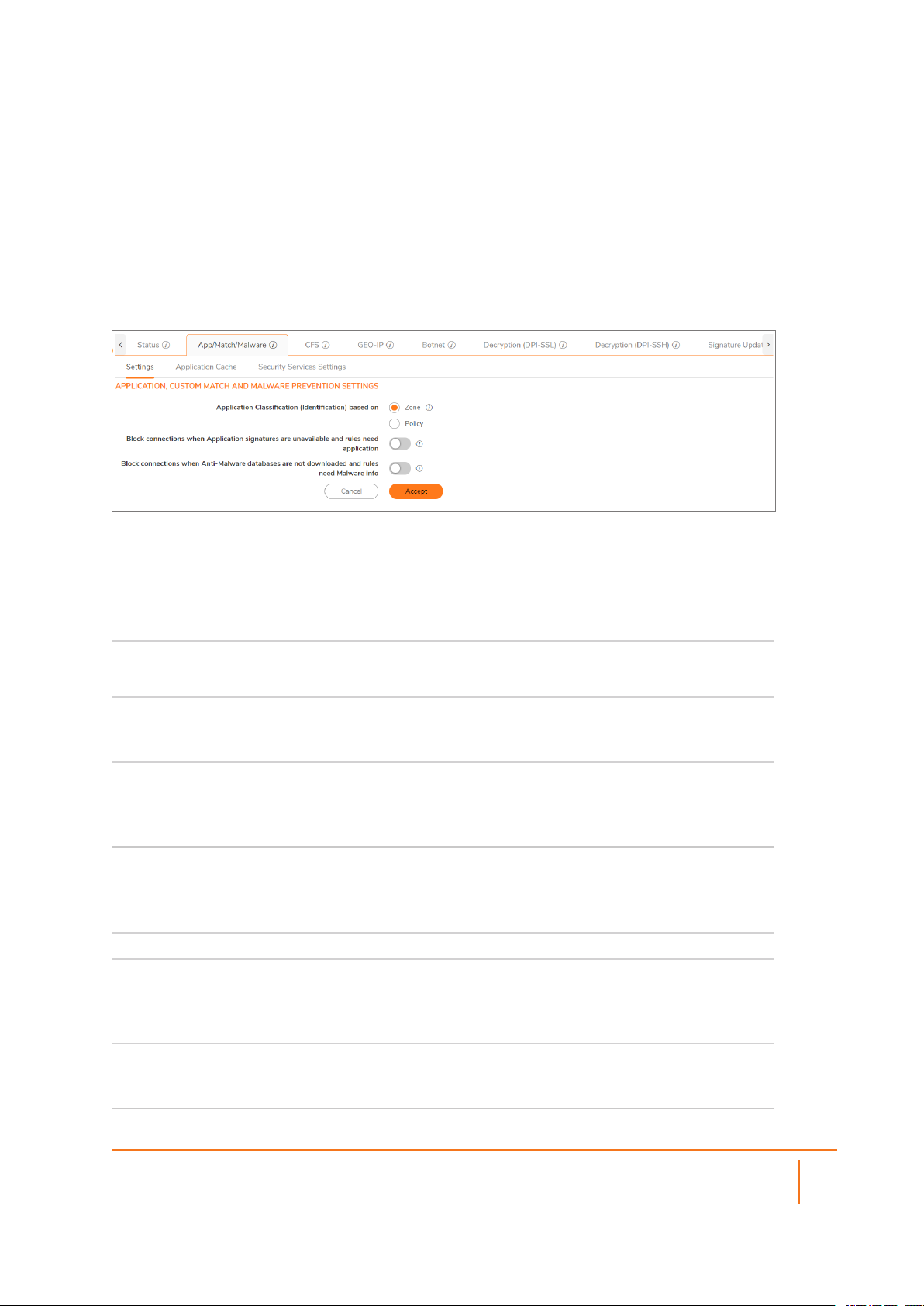
Configuring App/Match/Malware
Settings: Application, Custom Match and Malware Prevention Settings
Select the Application Classification
(Identification) based on:
Block connections when Application
signatures are unavailable and rules need
application
Block connections when Anti-Malware
databases are not downloaded and rules
need Malware info
Zone
Policy
When enabled, all connections are dropped when
application signatures are unavailable and policies
need application details to classify the packet.
When enabled, all connections are dropped when
Malware (Threats, Spyware and Virus) signatures
are not downloaded and policies actions need to
apply anti-malware profiles.
Application Cache
Enable Active Application Caching This enables/disables active application caching.
Use Cached Applications to Bypass DPI This enables/disables using the cache for
improved performance. If an active app cache
entry is found then application identification
engine is bypassed to further classify a packet.
Default Application Cache Timeout This is the system default timeout. Timeout in
seconds after when an entry is flushed from
application cache on no further activity.
SonicOSX 7 Rules and Policies Administration Guide
Settings
6

Default Application Cache Threshold Number of session after when an app cache entry
becomes active and usable.
Enable Global Application Cache Timeout This enables a global timeout for all components
of an application. When disabled then firewall
controls expiration of each app cache entry and is
depended on components inside each app cache
entry. Timeout in seconds after when an entry is
flushed from application cache on no further
activity.
Enable Global Application Cache Threshold This enables a global threshold for all components
of an application. When disabled then firewall
controls after how many sessions an application
cache becomes active and usable and is
depended on components inside each app cache
entry. Number of session after when an app cache
entry becomes active and usable.
Security Services Settings
Security Services Setting Maximum Security (Recommended): Inspect all
content with any threat probability
(high/medium/low).
Note: For additional performance capacity in this
maximum security setting, utilize SonicOSX DPI
Clustering.
Performance Optimized: Inspect all content with
a high or medium threat probability.
Note: Consider this performance optimized
security setting for bandwidth/CPU intensive
gateway deployments or utilize SonicOSX DPI
Clustering.
Reduce Anti-Virus and E-Mail Filter traffic for
ISDN connections
Drop all packets while IPS, GAV and AntiSpyware database is reloading
HTTP Clientless Notification Timeout for
Gateway AntiVirus and AntiSpyware
Enable or Disable.
Enable or Disable.
Indicate number of seconds before timeout.
SonicOSX 7 Rules and Policies Administration Guide
Settings
7
Configuring Content Filtering Service (CFS)
The CFS (Content Filtering Service) page provides a list of the filtering types and gives the link to the pages
for finding SonicWall CFS objects and policies. Internet Content Filtering equips SonicWall to monitor usage
and control access to objectionable Web content according to established Acceptable Use Policies.
To configure CFS:
1.
Navigate to POLICY | Rules and Policies > Settings | CFS.
The CFS page appears.
2.
Click the tab for the Content Filtering Type to select the content filtering options you want to view:
l SonicWall CFS - SonicWall CFS is the standard content filtering service.
l CFS Custom Category - Allows the configuration of new custom CFS category entries.
Topics:
l Sonicwall CFS
l CFS Custom Category
SonicWall CFS
This allows you to configure client Content Filtering Service (CFS) settings in SonicOSX. The default
SonicWall Content Filtering Service policy is available without a CFS subscription. With a valid advanced
CFS subscription, you can create custom CFS policies and apply them to network zones or to groups of
users within your organization.
After you have configured a CFS policy, you can configure client content filtering settings.
SonicOSX offers client content filtering protection on a subscription-basis through a partnership with
McAfee.
Topics:
l Global Settings
l SonicWall CFS
SonicOSX 7 Rules and Policies Administration Guide
Settings
8

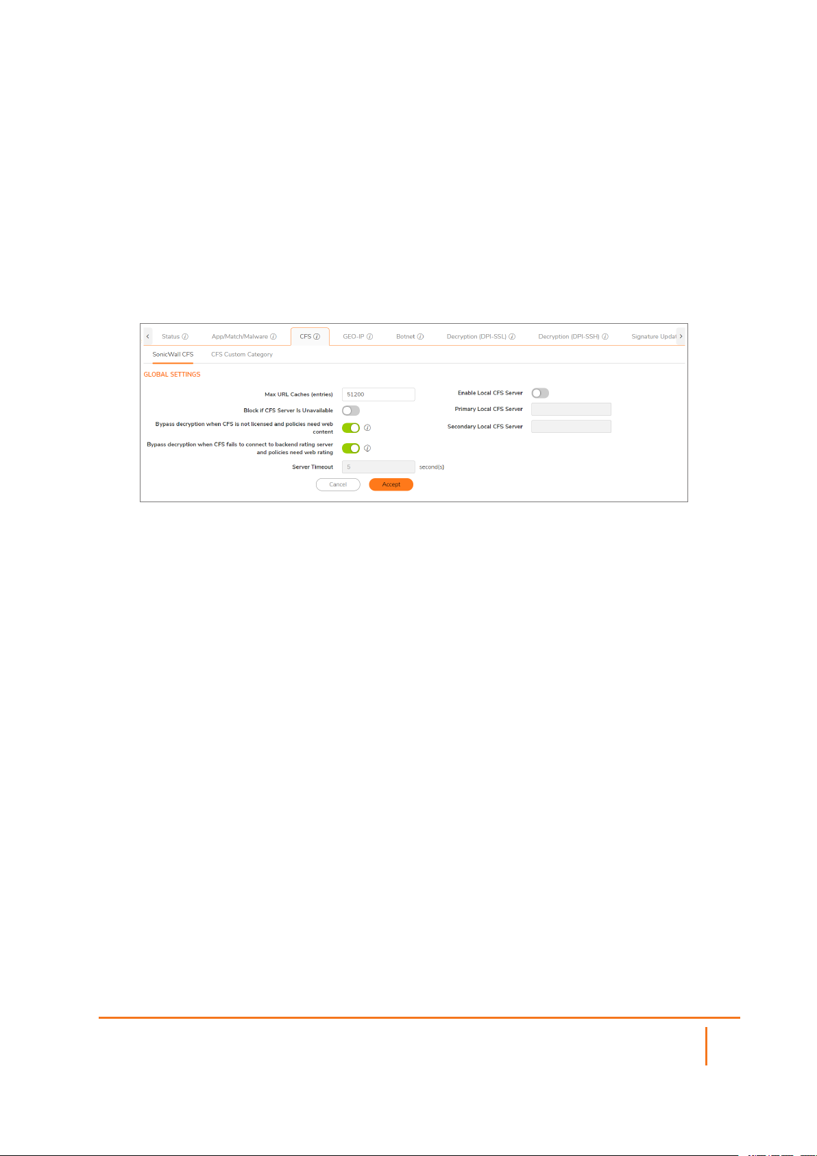
Global Settings
The Global Settings section of the Content Filter page brings up the information for defining the global
settings for CFS policies. Many of the fields on this page have an i (information) icon on the right, which
gives more information about that field. The Global Settings section provides these configuration options:
Enable Content Filtering Service This setting defaults to Enabled.
Max URL Cache Entries You can select the maximum number of URL entries that
can be cached. The minimum is 25,600 and the maximum
is 51,200. In the note beneath this field, there is a link on
the word "here" that gives the supported range for the
selected model.
Block if CFS Server is Unavailable When this option is selected, if the CFS server is detected
as unavailable, then all web access is blocked.
Bypass decryption when CFS is not
licensed and policies need web
content
Bypass decryption when CFS fails to
connect to backend rating server
and policies need web rating
Server Timeout If the network security appliance does not get a response
Enable Local CFS Server Check this box for the local CFS server. This setting
Primary Local CFS Server This field holds the IP address for primary local CFS server.
Secondary Local CFS Server This field holds the IP address for secondary local CFS
When enabled, all connections are bypassed when the
GEO-IP map database is not downloaded and your policies
require country details.
When enabled, all web client connections are bypassed
when the CFS is unable to connect to the backend servers
and your policies require web stream rating data (URL
ratings).
from the CFS server within this timeout value, the sever is
marked as unavailable. The minimum is two seconds, the
maximum is 10 seconds, and the default is five seconds.
This setting is not available when Block if CFS Server is
Unavailable is not checked.
defaults to disabled.
It becomes available when Enable Local CFS Server is
checked.
server. It becomes available when Enable Local CFS
Server is checked.
CFS Custom Category
The CFS Custom Category section allows the configuration of new custom CFS category entries. The
administrator can create custom policies and categories, and insert the domain name entries into the
existing, flexible CFS rating category structure. Categories are added and deleted on the page that follows:
1.
Navigate to POLICY | Rules and Policies > Settings > CFS > CFS Custom Category.
2.
Click Enable CFS Custom Category.
SonicOSX 7 Rules and Policies Administration Guide
Settings
9

3.
Click +Add to bring up a dialog box where you can choose from a list of categories to add to the CFS
categories in your system.
4.
Choose the Domain name and the custom categories, then click Save to add them.
5.
Click Accept on the CFS Custom Category page to save your changes.
Geo-IP
The Settings page in POLICY | Rules and Policies > Settings > GEO-IP > Settings provides a group of
settings that can be configured for Geo-IP Filtering. Several of the settings have (information) icons next to
them that give screen tips about that setting. The GEO-IP Filter feature allows administrators to block
connections to or from a geographic location based. SonicWall appliances use IP addresses to determine
the location of the connection.
Policy-based Settings
To enable Policy-based settings:
1.
When Block connections when Geo IP database is not downloaded and rules need Geo
locationis enabled, all connections are dropped when the Geo-IP map database is not downloaded
and your policies still need country details.
2.
When Bypass decryption when Geo IP database is not downloaded and policies need Geo
location is enabled, all connections bypass decryption when the Geo-IP map database is not
downloaded and your policies still need country details.
Global Settings
To enable Global settings:
1.
Enable Custom List - This option is selected by default. Custom lists are sometimes used to correct
a false country assignment for an IP address. When the checkbox is selected, Override Firewall
Countries by Custom List is made available.
2.
Override Firewall Countries by Custom List - This selection is only available when Enable
Custom List is enabled. It allows your custom list to override the firewall list where there are
differences. Unless you select this Override, the firewall list takes precedence, even when you have
enabled a custom list.
3.
Click Accept to save your settings.
Custom List
The POLICY | Rules and Policies > Settings > GEO-IP > Custom List allows you to create custom
country lists of IP addresses to either block or allow. This can be useful, for example, if an IP address is
mistakenly associated with a blocked country, and you want it to be allowed. Having a custom country list
can solve this problem by overriding the firewall country associated with the particular IP address.
SonicOSX 7 Rules and Policies Administration Guide
Settings
10

For the network security appliance to use the Custom List first, you must enable it and select Override
Firewall List.
To add a custom list address object:
1.
Click +Add to bring up the Add Address Location dialog box.
2.
From the IP Address list, select an IP Address object/group.
3.
From the Country list, select a country.
4.
Optionally, you can add a comment in the Comment field.
5.
Click Save.
Topics:
l Editing a Custom List Entry
l Deleting Custom List Entries
Editing a Custom List Entry
To modify an existing Custom Country List:
1.
Navigate to POLICY | Rules and Policies > Settings > GEO-IP > Custom List.
2.
Select the Custom List entry you would like to modify and mouse-over the entry.
The Edit/Delete icons appear on the right side of the entry.
3.
Click the Edit icon.
The Edit Address Location dialog appears.
4.
Make any necessary changes.
5.
Click Save.
Deleting Custom List Entries
To delete an existing Custom Country List:
1.
Navigate to POLICY | Rules and Policies > Settings > GEO-IP > Custom List.
2.
Select the Custom List entry you would like to delete and mouse-over the entry.
The Edit/Delete icons appear on the right side of the entry.
3.
Click the Delete icon.
The Delete Custom Geo-IP Filter List confirmation dialog appears.
4.
Click Confirm to delete the entry.
Using Geo-IP Diagnostics
The POLICY | Rules and Policies > Settings > GEO-IP > Diagnostics page provides access to several
tools:
l Geo-IP Cache Statistics
l Custom Countries Statistics
SonicOSX 7 Rules and Policies Administration Guide
Settings
11

l Show Resolved Locations
l Incorrectly Marked Address
l Check GEO Location Server Lookup
Botnet
The Botnet tab allows you to block connections to or from Botnet command and control servers, and make
custom Botnet lists. It also allows you to create a custom message to send when you block a web site, or to
allow dynamic Botnet HTTP authentication. Many of the selections on this page have an Information icon
that you can hover over for a screen tip.
Topics:
l Configuring Botnet Settings
l Creating Custom Botnet Lists
l Viewing Dynamic Botnet Lists
l Configuring a Dynamic Botnet List Server
l Using Botnet Filter Diagnostics
Configuring Botnet Settings
To configure Botnet Policy-based Settings:
1.
Navigate to POLICY | Rules and Policies > Settings > Botnet | Settings.
2.
To block all servers that are designated as Botnet command and control servers, select Block
connections when Botnet signatures are unavailable and rules need botnet control. All
connection attempts are blocked. This option is selected by default.
Global Settings
1.
To enable the Custom Botnet List, select Enable Custom Botnet List. This option is not selected
by default.
If Enable Custom Botnet List is not selected, then only the Botnet database that resides on the
network security appliance is searched. Go to Step x. Enabling a custom list by selecting Enable
Custom Botnet List can affect country identification for an IP address:
a.
During Botnet identification, the custom Botnet list is searched first.
b.
If the IP address is not resolved, the firewall's Botnet database is searched.
If an IP address is resolved from the custom Botnet list, it can be identified as either a Botnet IP address or a
non-Botnet IP address, and action taken accordingly.
2.
Click Enable Dynamic Botnet List to affect the botnet identification, for an IP address, in the
following ways:
l If "Enable Dynamic Botnet List" is enabled, the IP address is looked up against the dynamic
botnet list. If not found, the default list from the backend database will be searched.
SonicOSX 7 Rules and Policies Administration Guide
Settings
12

l When "Enable Custom Botnet List" is enabled, the custom list will take precedence over the
dynamic botnet list. So an IP in the dynamic botnet list will be allowed by the Firewall if it is
marked as "not a botnet" in the custom list.
Dynamic Botnet List File Format
• The dynamic botnet file is a .txt file that lists all the IPs seperated by end-of-line character.
• Comment lines should start with # symbol.
• Blocking of only individual IP addresses are supported. If the file contains subnets, they will be
ignored.
• Blocking of only public IP addresses are supported. Private IP addresses in the list will be ignored.
• Empty Lines are OK.
• Max file size cannot exceed 32KB.
• Max number of IPs cannot exceed 2000.
• Example file
#------------------------------------
# Sample botnet file (botnet.txt).
#------------------------------------
# Botnet IPs List 1
1.1.1.1
2.2.2.2
# Botnet IPs List 2
1.1.210.16
1.1.210.17
#------------------------------------
# End of Dynamic Botnet List File.
#------------------------------------
3.
Select Enable Logging to log Botnet Filter-related events.
4.
Optionally, you can configure an exclusion list of all IPs belonging to the configured address
object/address group. All IPs belonging to the list are excluded from being blocked. To enable an
exclusion list, select an address object or address group from the Botnet Exclusion Object list.
5.
Click Accept.
Creating Custom Botnet Lists
Address Object Name of the address object or address group object.
Botnet Icon indicating whether the entry was defined as a Botnet when created. A
black circle indicates a Botnet, a white circle a non-Botnet.
Comments Any comments you added about the entry.
Configure Contains Edit and Delete icons for the entry.
Total Displays the number of entries in the Custom Botnet List.
An IP address can be wrongly marked as Botnet. This kind of misclassification can cause incorrect/unwanted
filtering of an IP address. Having a custom Botnet list can solve this problem by overriding the Botnet tag for
a particular IP address.
SonicOSX 7 Rules and Policies Administration Guide
Settings
13

Topics:
l Creating a Custom Botnet List
l Editing Custom Botnet List Entries
Creating a Custom Botnet List
For the firewall to use the custom Botnet list, you must enable it as described in Configuring Botnet Filters.
To create a custom Botnet list::
1.
Navigate to the POLICY | Rules and Policies > Settings > Botnet | Custom Botnet List.
2.
Click +Add. The Add Address Location dialog displays.
3.
Select an IP address object or create a new address object from the A Botnet IP Address list:
An address object cannot overlap any other address objects in the custom country list. Different address
objects, however, can have the same country ID.
l Create new address object… – the Add Address Location dialog displays.
1.
Create a new address location. Allowed types are:
a.
Host
b.
Range
c.
Network
d.
A group of any combination of the first three types
All other types are disallowed types and cannot be added to the custom Botnet list.
l Create new address group… – the Add Address Location dialog displays.
1.
Create a new address object.
l Already defined address object or address group
1.
If this address object is a known Botnet, select the Botnet checkbox.
2.
Optionally, add a comment in the Comment field.
3.
Click Save.
Editing Custom Botnet List Entries
To edit a custom Botnet list entry:
1.
In the Custom Botnet List table, click the Edit icon in the Configure column for the entry to be
edited. The Add Address Locationdialog displays the entry.
2.
Make your changes.
3.
Click Save.
The Custom Botnet List table is updated.
SonicOSX 7 Rules and Policies Administration Guide
Settings
14

Viewing Dynamic Botnets Lists
Index
IP Address
Total
Name of the botnet or botnet group object.
Location of the botnet source
Displays the number of entries in the Dynamic Botnet List.
An IP address can be wrongly marked as Botnet. This kind of misclassification can cause incorrect/unwanted
filtering of an IP address. Having a dynamic Botnet list can solve this problem by overriding the Botnet tag
for a particular IP address.
Configuring a Dynamic Botnet List Server
With SonicOSX, username and passwords for HTTP URLs in the dynamic Botnet configuration are
accepted, and the information is transmitted in the HTTP header so the network security appliance has the
required information.
To configure dynamic HTTP authentication:
1.
Navigate to POLICY | Rules and Policies > Settings > Botnet > Dynamic Botnet List.
2.
Select Enable botnet list download periodically. This option is not selected by default.
3.
From Download Interval, select the frequency of downloads:
l 5 minutes (default)
l 15 minutes
l 1 hour
l 24 hours
The network security appliance downloads the Botnet file from the server at the specified interval.
1.
From Protocol, select the protocol in which the network security appliance has to communicate with
the backend server to retrieve the file:
l FTP (default)
l HTTPS
2.
In the Server IP Address field, enter the IP address of the server to which the Botnet list file will be
downloaded.
3.
In the Login ID field, enter the login ID the network security appliance is to use to connect to the
server.
4.
In the Password field, enter the password the network security appliance is to use to connect to the
server.
5.
In the Directory Path field, enter the directory path the firewall from which the network security
appliance retrieves the Botnet file. This server directory path is relative to the default root directory.
6.
In the File Name field, enter the name of the file on the server to be downloaded .
7.
Click Save.
SonicOSX 7 Rules and Policies Administration Guide
Settings
15

Using Botnet Diagnostics
The POLICY | Rules and Policies > Settings > Botnet > Diagnostics page provides access to several
tools:
l Botnet Cache Statistics
l Botnets Statistics
l Show Resolved Botnet Locations
l Check Botnet Server Lookup
l Incorrectly Marked Address
Botnet Cache Statistics
The Botnet Cache Statistics table contains this information:
l Location Server IP
l Resolved Entries
l Unresolved Entries
l Current Entry Count
l Max. Entry Count
l Botnets Detected
Botnets Statistics
The Diagnostics view displays statistics for both custom and dynamic Botnets. Both the Custom Botnets
Statistics and Dynamic Botnet Statistics tables display the same information about the number of entries in
the list and the number of times lookups have occurred for the entries:
l No of Entries
l No of Times Called
l No of Times Not Looked-up
l No of Times Resolved
Show Resolved Botnet Locations
When you click on Show Botnets in the Diagnostics section, a table of resolved IP addresses displays with
this information:
l Index
l IP Address – IP address of the Botnet
Check Botnet Server Lookup
The Botnet Filter also provides the ability to look up IP addresses to determine:
l Domain name or IP address
l Country of origin and whether the server is classified as a Botnet server
The Botnet Server Lookup tool can also be accessed from the DEVICE > Diagnostics page.
SonicOSX 7 Rules and Policies Administration Guide
16
Settings
To look up a Botnet server:
1.
Navigate to POLICY | Rules and Policies > Settings > Botnet > Diagnostics.
2.
Scroll to the Check BOTNET Server Lookup section.
3.
In the Lookup IP field, enter the IP address.
4.
Click Save.
Details on the IP address are displayed below the Result heading.
Incorrectly Marked Address
If you believe that a certain address is marked as a Botnet incorrectly, or if you believe an address should be
marked as a Botnet, report this issue at SonicWall Botnet IP Status Lookup by either:
l Clicking on the link in the Note in the POLICY | Rules and Policies > Settings > Botnet >
Diagnostics page
l Going to SonicWall Botnet IP Status Lookup.
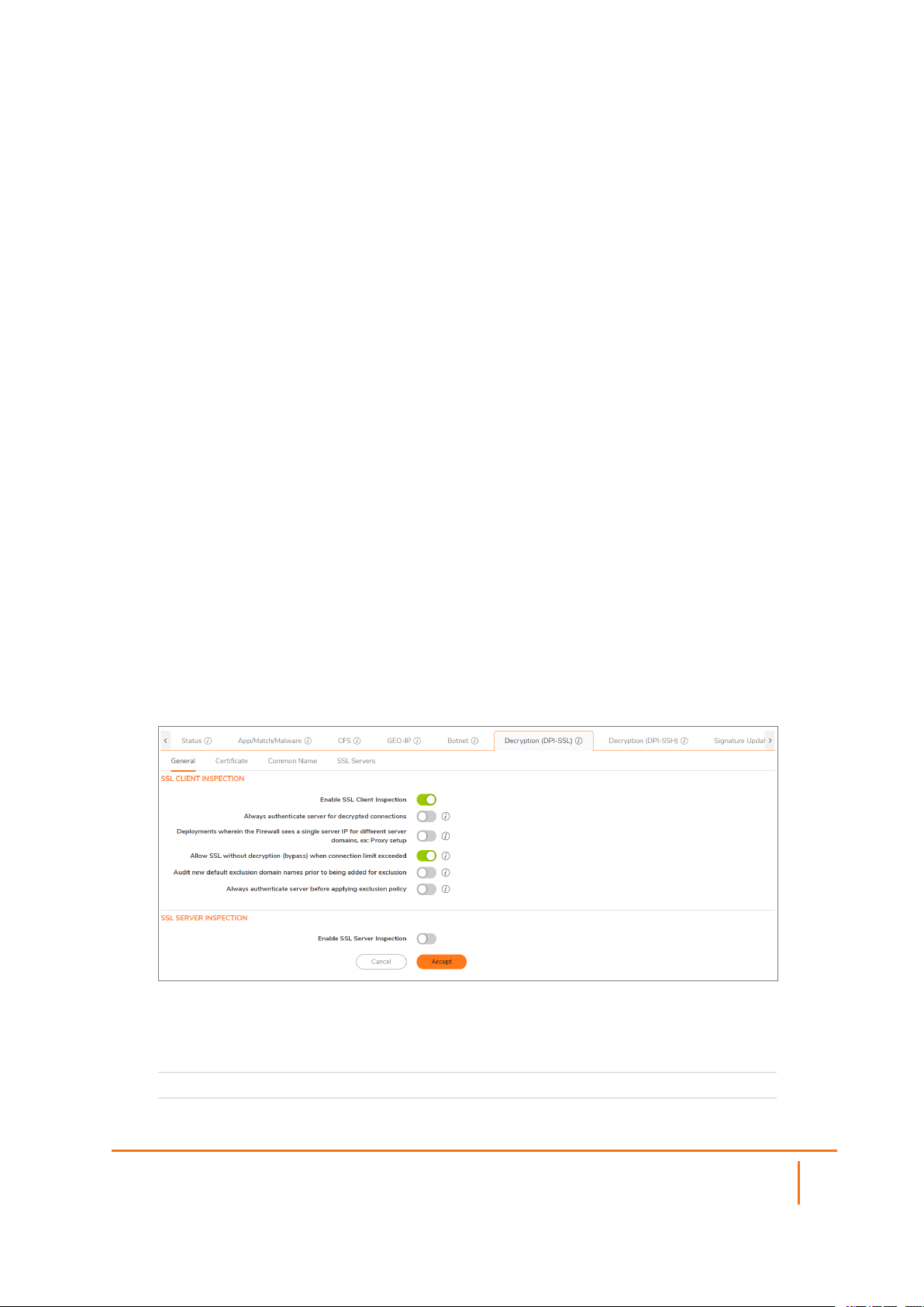
Decryption (DPI-SSL)
The Decryption (DPI-SSL) page provides a list of inspection types available. In the General tab, you can
configure settings for:
l SSL Client Inspection
l SSL Server Inspection
The configure the desired inspection type:
1.
Navigate to POLICY | Rules and Policies > Settings > Decryption (DPI-SSL) > General.
SSL Client Inspection
Enable SSL Client Inspection Click to enable SSL Client Inspection.
SonicOSX 7 Rules and Policies Administration Guide
17
Settings

Always authenticate server for
decrypted connections
Deployments wherein the
firewall sees a single server IP
for different server domains,
such as a Proxy setup
Allow SSL without decryption
(bypass) when connection limit
exceeded
Audit new default exclusion
domain names prior to being
added for exclusion
Always authenticate server
before applying exclusion
policy
When enabled for decrypted/intercepted connections,
DPI-SSL: Blocks connections to sites with untrusted
certificates. Blocks connections when the domain name in
the Client Hello cannot be validated against the Server
Certificate for this connection.
When disabled, use of a server IP address-based dynamic
cache is marked for exclusion.
When enabled, allows SSL to proceed without decryption
(bypass) when exceeding the connection limit. By default,
new connections are dropped when the connection
exceeds the limit.
Audits new built-in exclusion domain names prior to being
added for exclusion.
When enabled for excluded connections, DPI-SSL: Blocks
connections to sites with untrusted certificates. Blocks
connections when the domain name in the Client Hello
cannot be validated against the Server Certificate for this
connection.
SSL Server Inspection
Enable SSL Server
Inspection
Click to enable SSL Server Inspection.
Certificate
This certificate replaces the original certificate-signing authority only when that authority certificate is trusted
by the firewall. If the authority is not trusted, then the certificate is made self-signed.
To avoid certificate errors, choose a certificate that is trusted by devices that are protected by DPI-SSL.
To manage your certificates, go to Device | Settings > Certificates. Certificates signed by an authority
trusted by the firewall are re-signed using this certificate.
Common Name
You can use Common Name exclusions and inclusions to exclude particular websites from limitation.
DPI-SSL Default Exclusions Status
Indicates with a timestamp the last time the exclusion list was enforced and the last time the exclusions
were checked.
SonicOSX 7 Rules and Policies Administration Guide
Settings
18
Common Name Exclusions/Inclusions
You can use to Search and filtering options to locate or reduce common names in your list. You can also
+Add more exclusions by clicking +Add and completing the form.
Update Default Exclusions Manually
If you work in a closed environment or prefer to update default exclusions manually, download the
exclusions file from www.MySonicWall.com to your disk, then import the file.
SSL Servers
Server DPI-SSL allows you to configure pairings of an address object and certificate to typically
offload/protect an internal Server from inbound WAN access. Options include:
l Address Object/Group - When the appliance detects SSL connections (from the WAN) to this
address object, it presents the paired certificate and negotiates SSL with the connecting client
(typically in the WAN).
l SSL Certificate - This certificate is used to sign traffic for each server that has DPI-SSL Server
inspection performed on its traffic
l Cleartext - If Cleartext is selected, a standard TCP connection is made from the appliance to the
server (in the LAN) on the original port. For this to work, a NAT policy needs to be added. If the
pairing is not cleartext, then an SSL connection to the server is negotiated.
To view and manage certificates, go to DEVICE | Settings > Certificates.
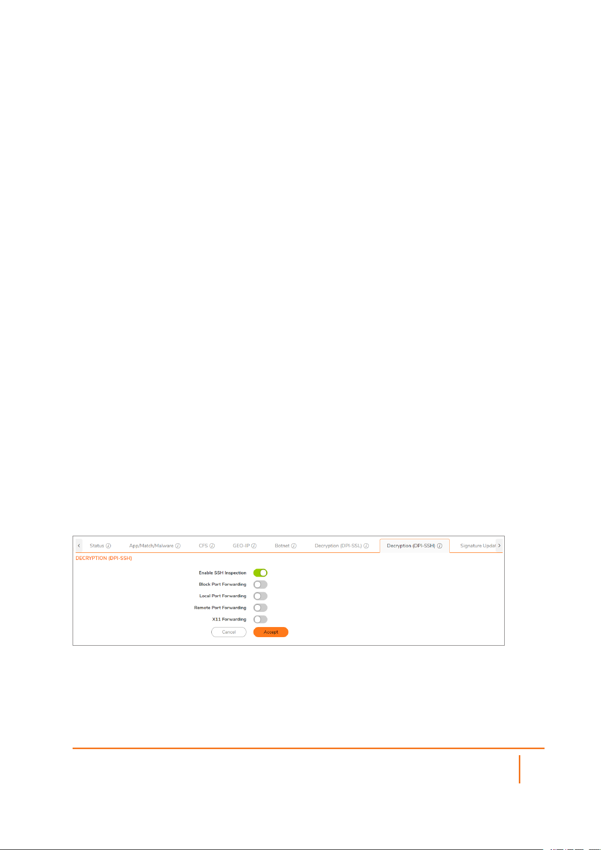
Decryption (DPI-SSH)
The Anti-Spyware Service service does not work for DPI-SSH because TCP streams for Anti-Spyware are not
supported. If the checkbox is checked, the system takes no action. The Decryption Policies feature allows
you to decrypt and bypass connections.
To configure Decryption (DPI-SSH):
1.
Navigate to POLICY | Rules and Policies > Settings > Decryption (DPI-SSH).
2.
For Enable SSH Inspection, click enable to activate SSH Inspection.
SonicOSX 7 Rules and Policies Administration Guide
Settings
19
3.
Block Port Forwarding - Enable Block Port forwarding to allow local or remote computers (for
example, computers on the internet) to connect to a specific computer or service within a private
LAN. Port forwarding translates the address and/or port number of a packet to a new destination
address and forwards it to that destination according the routing rules. Because these packets have
new destinations and port numbers, they can bypass the firewall security policies.
4.
Local Port Forwarding - Enable Local Port Forwarding to allow a computer on the local network to
connect to another server that might be an external server.
5.
Remote Port Forwarding - Enable to allow a remote host to connect to an internal server.
6.
X11 Forwarding - Use X11 forwarding as an alternative to forwarding a Remote Port or VNC
connection. It differs from Remote Port Forwarding or VNC in that remote application windows
appear seamlessly in your desktop, without forwarding a complete desktop. X11 forwarding is best
used with UNIX-style servers running applications intended to run under X11. For connections to
Windows servers, Remote Port Forwarding is the native option.
7.
Click Accept to save your changes.
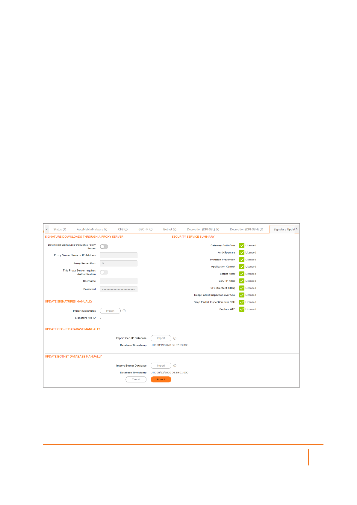
Signature Update
Manage signatures by manually uploading signature and map database files. Service licenses can be
downloaded, imported, updated, and monitored from the Signature Update tab. Follow the options as
shown.
SonicOSX 7 Rules and Policies Administration Guide
Settings
20
2
Security Policy
To configure Security Policy rules, the service or service group that the policy applies to must first be
defined. If it is not, you can define the service or service group and then create one or more rules for it.
The following procedure describes how to add, modify, reset to defaults, or delete Security Policy rules for
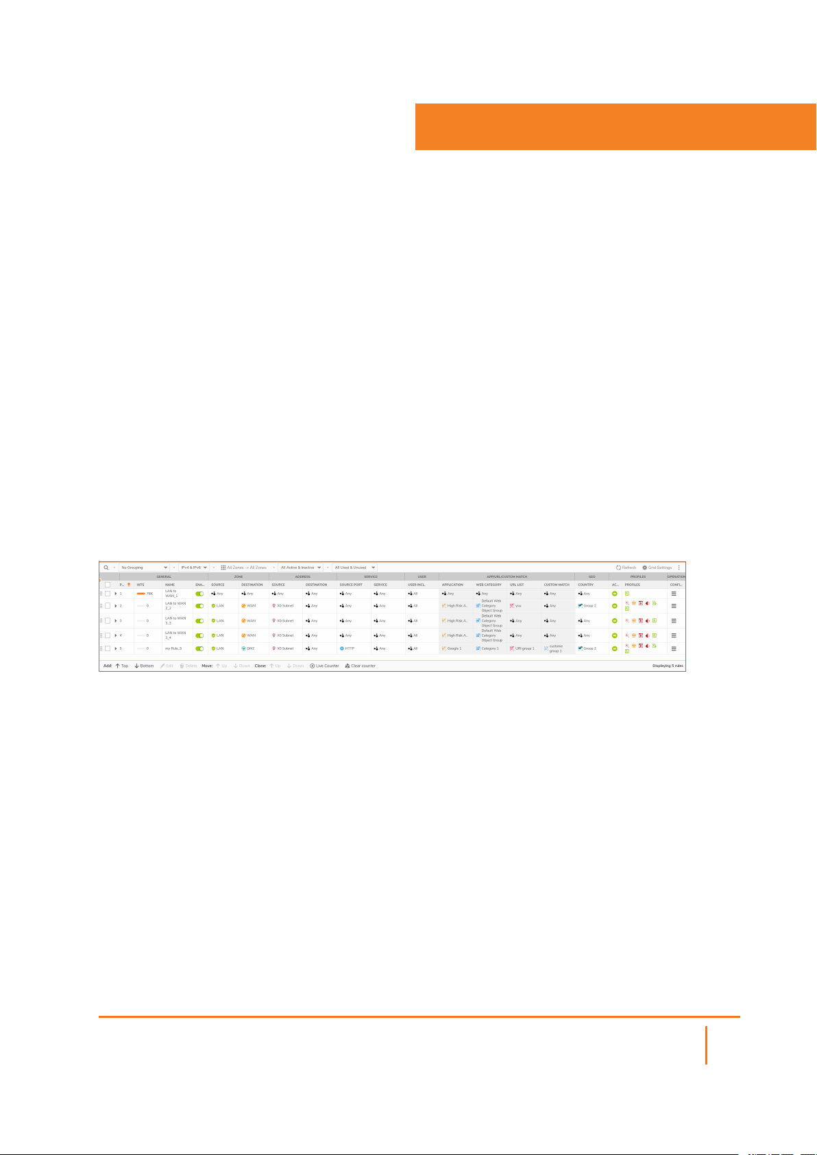
firewalls running SonicOSX. Paginated navigation and sorting by column header is supported on the Security
Policy screen. In the Security Policy table, you can click the column header to use for sorting. An arrow is
displayed to the right of the selected column header. You can click the arrow to reverse the sorting order of
the entries in the table.
By hovering your mouse over icons on the Security Policy page, you can display information about criteria,
such as an Source Port or Service.
IPv6 is supported for Security Policy. Search for IPv6 Security Policies in the Security Policy Search
section. A list of results displays in a table.
From there you can click the Configure icon for the Security Policy you want to edit. The IPv6 configuration
for Security Policy is almost identical to IPv4.
To configure a Security Policy:
1.
Navigate to POLICY | Rules and Policies > Security Policy. The Security Policy page displays.
The POLICY | Rules and Policies > Security Policy page enables you to select multiple
configuration screens for your security policies.
2.
From the bottom of the Security Policy table, click Add. The Adding Rule dialog displays.
SonicOSX 7 Rules and Policies Administration Guide
Security Policy
21
3.
Or, under the Configure column, click the Edit icon for the source and destination zones or
interfaces for which you are configuring a rule. The Editing Rule page for that zone/interface pair
displays.
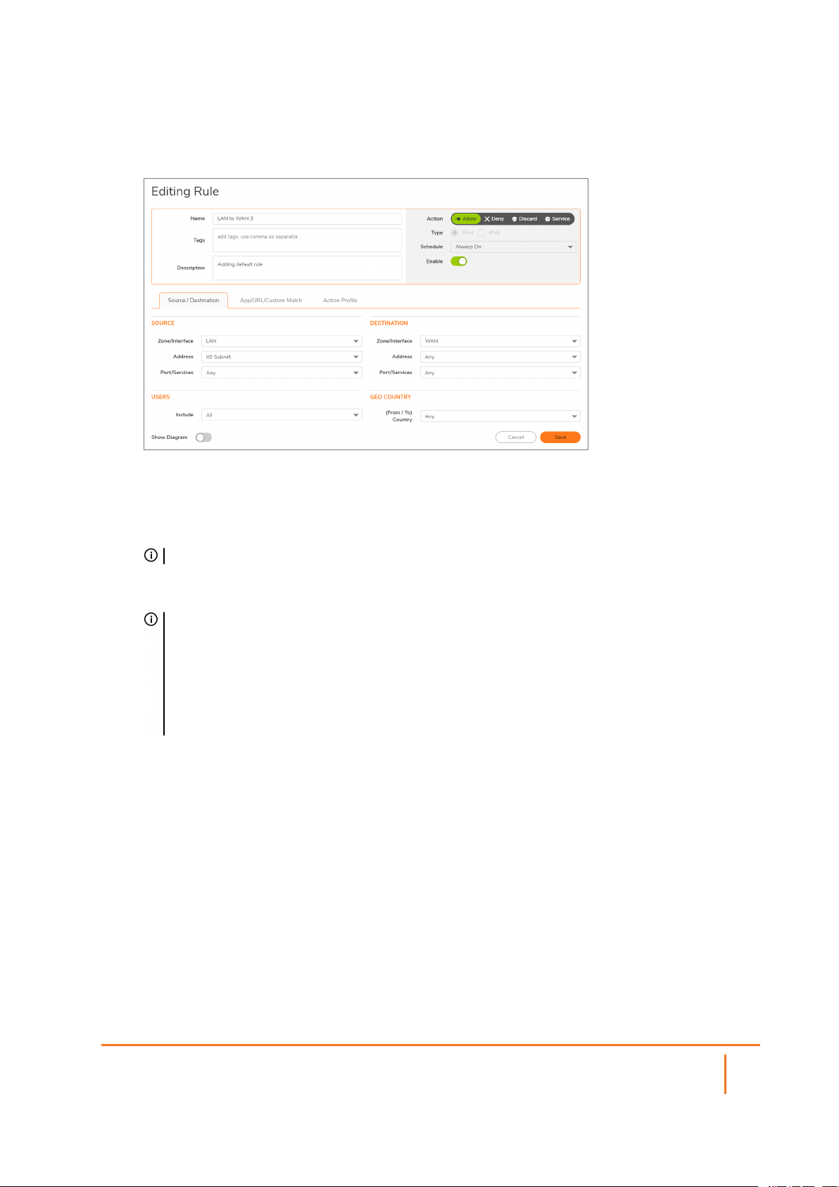
4.
In the top view, enter or edit the policy Name and any identifying Tags you would like to enter to help
sort your policies.
5.
Enter a Description of the policy and its intent.
6.
Select an Action, whether to Allow, Deny, or Discard access.
NOTE: If a policy has a “No-Edit” policy action, the Action settings are not editable.
7.
Specify the IP version in Type, IPv4 or IPv6.
8.
Set your Security Policy's Priority.
TIP: Higher numbers indicate lower priority. The lowest priority rule is the final/default rule
applied to matching traffic (traffic matching the defined attributes) when no higher priority rules
apply. Lower priority rules should be more general than rules with higher priorities.
If a higher priority rule does not match all the attributes, then the next rule is evaluated to see if it
applies, all the way down the list of rules. Rules with more specific matching attributes need to
be set at a higher priority or else a more general rule could match before that specific rule is
evaluated.
9.
Specify when the rule is applied by selecting a schedule or Schedule Group from the Schedule dropdown menu. If the rule is always applied, select Always On. If the schedule does not exist, refer to
Configuring Schedules.
10.
Click Enable to activate the policy schedule and enable logging.
11.
In the Source/Destination view, select the Source and Destination zones, and network address
objects, and port/services for each from the drop-down menus.
There are no default zones. Any is supported for both zone fields.
12.
For the Port/Services object in the Port/Services drop-down menus, if the service does not exist,
refer to Configuring Service Objects.
13.
Under Users, specify if this rule applies to all users or to an individual user or group in the Include
drop-down menu. You can exclude users as well using the Exclude drop-down menu.
14.
Under GEO Country, indicate a (From/To) Country from the drop-down menu.
15.
Click Save, and continue with App/URL/Custom Match and Action Profile.
SonicOSX 7 Rules and Policies Administration Guide
Security Policy
22
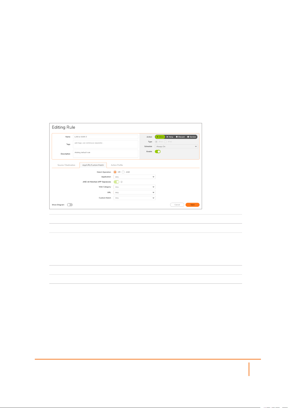
App/URL/Custom Match
You can add additional rule attributes by indicating the Match Operation, type of application to which this
rule would apply, whether or not to include Matched App Signatures, type of Web Categories, URLs, and
Custom Matches that could be applied.
To fill the App/URL/Custom Match options:
1.
Navigate to POLICY | Rules and Policies > Security Policy.
2.
Click Add. The Adding Rule dialog displays.
3.
Click the App/URL/Custom Match tab.
Match Operation
Application
AND All Matched
APP Signatures
Web Category
URL
Custom Match
4.
5.
Click Save to apply your changes. Click Action Profile to continue with the configuration.
Allows you to indicate whether to use either rule or both rules.
Select which group application to apply to this rule.
When this option is enabled, when more than one App Signature is
addressed within a flow or session, then all signatures must be
included in the app group configured previously, for the match to be
successful. When this option is disabled, any one signature among all
the signatures addressed would result in a successful match.
Indicate whether to apply defined group web categories.
Indicate whether to restrict defined URLs.
Indicate which custom match groups to include in the rule.
SonicOSX 7 Rules and Policies Administration Guide
Security Policy
23
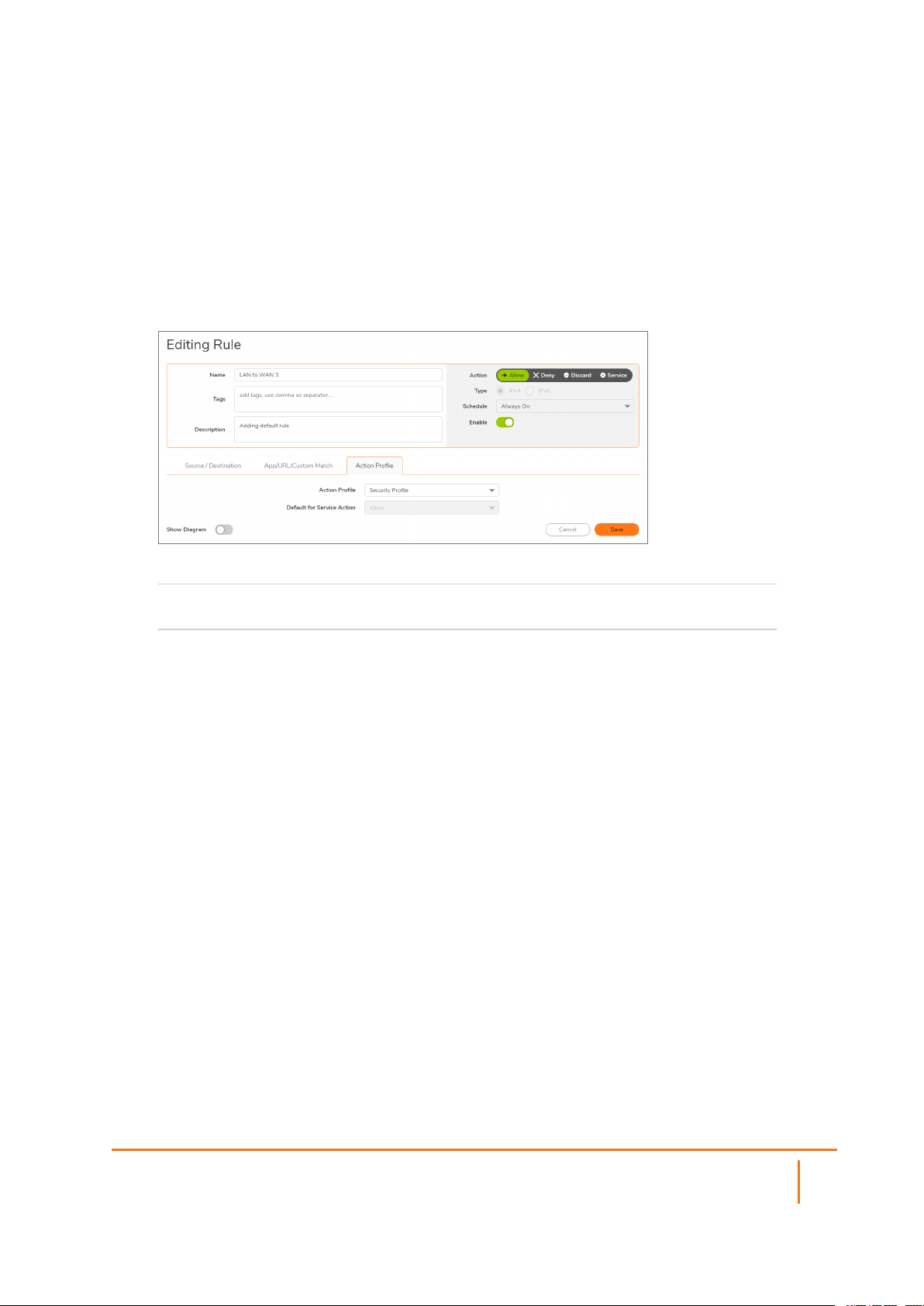
Action Profile
To enforce a predetermined Action Profile with your security policy.
To fill the Action Profile options:
1.
Navigate to POLICY | Rules and Policies > Security Policy.
2.
Click Add. The Adding Rule dialog displays.
3.
Click the Action Profile tab.
To enforce specific predetermined policy rules, select from the
Action Profile
Default for Service Action
available Action Profiles.
The default is to Allow use of the Action Profile.
SonicOSX 7 Rules and Policies Administration Guide
Security Policy
24

Topics:
l About NAT in SonicOS
l About NAT Load Balancing
l About NAT64
l About FQDN Based NAT
l About Source MAC Address Override
l Viewing NAT Policy Entries
l Adding or Editing NAT or NAT64 Policies
l Deleting NAT Policies
l Creating NAT Policies: Examples
3
NAT Policy
About NAT in SonicOSX
IMPORTANT: Before configuring NAT policies, be sure to create all address objects associated with the
policy. For instance, if you are creating a one-to-one NAT policy, be sure you have address objects for
your public and private IP addresses.
TIP: By default, LAN to WAN has a NAT policy predefined on the firewall.
The Network Address Translation (NAT) engine in SonicOSX allows you to define granular NAT policies
for your incoming and outgoing traffic. By default, the firewall has a preconfigured NAT policy to allow all
systems connected to the X0 interface to perform many-to-one NAT using the IP address of the X1 interface,
and a policy to not perform NAT when traffic crosses between the other interfaces. NAT policies are
automatically created when certain features are enabled, such as the Enable Local Radius Server option
in WLAN zone configuration, and are deleted when the feature is disabled. This section explains how to set
up the most common NAT policies.
Understanding how to use NAT policies starts with examining the construction of an IP packet. Every packet
contains addressing information that allows the packet to get to its destination, and for the destination to
respond to the original requester. The packet contains (among other things) the requester’s IP address, the
protocol information of the requester, and the destination’s IP address. The NAT Policies engine in
SonicOSX can inspect the relevant portions of the packet and can dynamically rewrite the information in
specified fields for incoming, as well as outgoing traffic.
SonicOSX 7 Rules and Policies Administration Guide
NAT Policy
25

You can add up to 512 - 2048 NAT policies depending on the SonicWall network security platform, and they
can be as granular as you need. It is also possible to create multiple NAT policies for the same object — for
instance, you can specify that an internal server use one IP address when accessing Telnet servers, and to
use a totally different IP address for all other protocols. Because the NAT engine in SonicOSX supports
inbound port forwarding, it is possible to hide multiple internal servers off the WAN IP address of the firewall.
The more granular the NAT policy, the more precedence it takes.
The Maximum Routes and NAT Policies Allowed per Firewall Model table shows some of the maximum
numbers of routes and NAT policies allowed for each network security appliance model running SonicOSX.
Additional models could be supported similarly.
MAXIMUM ROUTES AND NAT POLICIES ALLOWED PER FIREWALL MODEL
Model
NSa 9650
NSa9450
NSa9250
NSa6650
NSa 5650
NSa4650
NSa3650
NSa2650
SM 9600
SM 9400
SM 9200
Routes
NAT Policies Model
4096 8192 2048
4096 8192 2048
4096 8192 2048
3072 4096 2048
2048 4096 2048
2048 4096 2048
1088 2048 1024
1088 2048 1024
3072 4096 2048
3072 4096 2048
3072 4096 2048
NSA 6600
NSA 5600
NSA 4600
NSA 3600
NSA 2600
Routes
2048 4096 2048
2048 4096 2048
1088 2048 1024
1088 2048 1024
1088 2048 1024
NAT
PoliciesStatic Dynamic Static Dynamic
About NAT Load Balancing
Network Address Translation (NAT) and Load Balancing (LB) provide the ability to balance incoming
traffic across multiple, similar network resources. Do not confuse this with the Failover & Load Balancing
feature in SonicOS. While both features can be used in conjunction, Failover & Load Balancing is used to
actively monitor WAN connections and act accordingly on failure/recovery of the WAN interface(s), and NAT
LB is primarily used to balance incoming traffic.
Load Balancing distributes traffic among similar network resources so that no single server becomes
overwhelmed, allowing for reliability and redundancy. If one server becomes unavailable, traffic is routed to
available resources, providing maximum up-time.
This details how to configure the necessary NAT, load balancing, health checks, logging, and firewall rules
to allow systems from the public Internet to access a virtual IP that maps to one or more internal systems,
such as web servers, FTP servers, or SonicWall SMA appliances. This virtual can be independent of the
firewall or it can be shared, assuming the firewall itself is not using the port(s) in question.
SonicOSX 7 Rules and Policies Administration Guide
NAT Policy
26

NOTE: The load balancing capability in SonicOS, while fairly basic, satisfies the requirements for many
network deployments. Network administrators with environments needing more granular load
balancing, persistence and health-check mechanisms are advised to use a dedicated third-party loadbalancing appliance.
Topics:
l Determining the NAT LB Method to Use
l Caveats
l How Load Balancing Algorithms are Applied
l Sticky IP Algorithm Examples
Determining the NAT LB Method to Use
DETERMINE WHICH NAT LB METHOD TO USE
Requirement Deployment Example NAT LB Method
Distribute load on server
equally without need for
External/Internal servers (such as,
web or FTP)
persistence
Indiscriminate load balancing
without need for persistence
Requires persistence of client
connection
External/Internal servers (such as,
web or FTP)
E-commerce site, Email Security,
SonicWall SMA appliance
(Any publicly accessible servers
requiring persistence)
Precise control of remap of
source network to a destination
range
Precise control of remap of
source network and destination
LAN to DMZ Servers
Email Security, SonicWall SMA
appliance
Internal Servers (such as, Intranets
or Extranets)
network
Caveats
l Only two health-check mechanisms (ICMP ping and TCP socket open)
l No higher-layer persistence mechanisms (Sticky IP only)
l No “sorry-server” mechanism if all servers in group are not responding
l No “round robin with persistence” mechanism
l No “weighted round robin” mechanism
l No method for detecting if resource is strained
Round Robin
Random Distribution
Sticky IP
Block Remap
Symmetrical Remap
While there is no limit to the number of internal resources that the SonicWall network security appliance can
load-balance to and there is no limit to the number of hosts it can monitor, abnormally large load-balancing
groups (25+ resources) may impact performance.
SonicOSX 7 Rules and Policies Administration Guide
NAT Policy
27

How Load Balancing Algorithms are Applied
Round Robin Source Address connects to Destination Address alternately
Random
Distribution
Sticky IP Source Address connects to same Destination Address
Block Remap Source network is divided by size of the Destination pool to create logical
Symmetrical Remap Source Address maps to Destination Address (for example, 10.1.1.10 >
Source Address connects to Destination Address randomly
segments
192.168.60.10)
Sticky IP Algorithm Examples
Source IP is modulo with the size of the server cluster to determine the server to remap it to. The following
two examples show how the Sticky IP algorithm works:
l Example One - Mapping to a Network
l Example Two - Mapping to a IP Address Range
Example One - Mapping to a Network
192.168.0.2 to 192.168.0.4
Translated Destination = 10.50.165.0/30 (Network)
Packet Source IP = 192.168.0.2
192.168.0.2 = C0A80002 = 3232235522 = 11000000101010000000000000000010
(IP -> Hex -> Dec -> Binary)
Sticky IP Formula = Packet Src IP = 3232235522 [modulo] TransDest Size = 2
= 3232235522 [modulo] 2
= 0 (2 divides into numerator evenly. There is no remainder, thus 0)
Sticky IP Formula yields offset of 0.
Destination remapping = 10.50.165.1
Example Two - Mapping to an IP Address Range
192.168.0.2 to 192.168.0.4
Translated Destination = 10.50.165.1 - 10.50.165.3 (Range)
Packet Src IP = 192.168.0.2
192.168.0.2 = C0A80002 = 3232235522 = 11000000101010000000000000000010
(IP -> Hex -> Dec -> Binary)
Sticky IP Formula = Packet Src IP = 3232235522 [modulo] TransDest Size = 3
= 3232235522 [modulo] 4
= 1077411840.6666667 - 1077411840
SonicOSX 7 Rules and Policies Administration Guide
NAT Policy
28

= 0.6666667 * 3
= 2
Sticky IP Formula yields offset of 2.
Destination remapping to 10.50.165.3
About NAT64
SonicOS supports the NAT64 feature that enables an IPv6-only client to contact an IPv4-only server through
an IPv6-to-IPv4 translation device known as a NAT64 translator. NAT64 provides the ability to access legacy
IPv4-only servers from IPv6 networks; a SonicWall with NAT64 is placed as the intermediary router.
As a NAT64 translator, SonicOS allows an IPv6-only client from any zone to initiate communication to an
IPv4-only server with proper route configuration. SonicOS maps IPv6 addresses to IPv4 addresses so IPv6
traffic changes to IPv4 traffic and vice versa. IPv6 address pools (represented as address objects) and IPv4
address pools are created to allow mapping by translating packet headers between IPv6 and IPv4. The IPv4
addresses of IPv4 hosts are translated to and from IPv6 addresses by using an IPv6 prefix configured in
SonicOS.
The DNS64 translator enables NAT64. Either an IPv6 client must configure a DNS64 server or the DNS
server address the IPv6 client gets automatically from the gateway must be a DNS64 server. The DNS64
server of an IPv6-only client creates AAAA (IPv6) records with A (IPv4) records. SonicOS does not act as a
DNS64 server.
IMPORTANT: Currently, NAT64:
l Only translates Unicast packets carrying TCP, UDP, and ICMP traffic.
l Supports FTP and TFTP application-layer protocol streams, but does not support H.323, MSN,
Oracle, PPTP, RTSP, and RealAudio application-layer protocol streams.
l Does not support IPv4-initiated communications to a subset of the IPv6 hosts.
l Does not support Stateful High Availability.
For NAT64 traffic matches, two mixed connection caches are created. Thus, the capacity for NAT64
connection caches is half that for pure IPv4 or IPv6 connections.
Use of Pref64::/n
Pref64::/n is an IPv6 prefix used on the access network for protocol translation between IPv6 and IPv4. The
Pref64::/n prefix is configured in SonicOS. A well-known Pref64::/n prefix, 64:ff9b::/96, is automatically
created by SonicOS.
Pref64::/n defines a network that can go from an IPv6-only client through NAT64 to an IPv4-only client. In
SonicOS, an address object of Network type can be configured to include all addresses with Pref64::/n. This
address object represents all IPv6 clients that can do NAT64.
The DNS64 server uses Pref64::/n to judge if an IPv6 address is an IPv4-embedded IPv6 address by
comparing the first n bits with Pref64::/n. DNS64 creates IPv4-embedded IPv6 addresses by synthesizing
Pref64::/n with IPv4 address records and sending a DNS response to IPv6-only clients.
For configuring a Pref64::/n address object, see Default Pref64 Address Object.
SonicOSX 7 Rules and Policies Administration Guide
29
NAT Policy

About FQDN-based NAT
SonicOS/X supports NAT policies using FQDN Address Objects for the original source/destination.
Use cases include:
l Specifying public IP addresses with FQDN to a local server
l Specifying a public server with FQDN for consistency across replacement with a server that has a
known IP address
l Routing traffic from/to a FQDN to have a source IP address other than the outbound interface IP.
The following functionality is supported:
l The original source/destination can be a pure FQDN or an address group with FQDN(s) and other
IPv4 or IPv6 addresses, depending on the IP version of the NAT policy. A new FQDN address object
can be directly created from the POLICY | Rules and Policies > NAT Policy page.
FQDN is not supported for the translated source/destination.
l IP version options are provided for a NAT policy only if the version is ambiguous based on settings for
original/translated source/destination fields. Either IPv4 or IPv6 must be selected.
l Mousing over an FQDN object of a NAT policy displays the IP addresses in the same IP version as
the NAT policy.
l When NAT translation is performed, only the IP addresses in the NAT's IP version are considered.
l The Advanced page is disabled if FQDN is used in either or both the original source/destination
fields.
If probing is enabled and/or the NAT method is configured to a non-default value such as Sticky IP,
neither of original source/destination address objects can be modified to contain an FQDN.
l FQDN based NAT policies are supported in High Availability configurations.
About Source MAC Address Override
An internal option has been added that allows you to replace the source MAC address of an outbound or
port-forwarded packet with the MAC address specified in a NAT policy. By default, without this option, the
MAC address of the output interface is used as the source MAC address of the packet.
This feature is also disabled by default, but can be enabled using an internal setting. Contact SonicWall
Technical Support for information about internal settings.
Viewing NAT Policy Entries
Topics:
l Changing the Display
l Filtering the Display
SonicOSX 7 Rules and Policies Administration Guide
NAT Policy
30

Changing the Display
The POLICY | Rules and Policies > NAT Policy page provides display options at the top and bottom of
the page, including Search, IP Version, Active and Inactive Rules, Used and Unused Rules, Add,
Delete, Move, Clone, and Refresh.
You can change the display of your NAT policies by selecting one of the following options in the drop-down
menus at the top of the page:
All Default & Custom Displays all the NAT rules including Custom Rules and Default Rules.
Initially, before you create NAT policies, only displays the Default Rules.
Custom Displays only those Custom Rules you configure.
Default Displays only Default Rules.
All Active & Inactive Displays all the Nat Rules including Active and Inactive Rules. Initially,
before you create any NAT policies, only the default Active and Inactive Rules
are displayed.
Active Rules Displays only the Active Rules.
Inactive Rules Displays only Inactive Rules.
All Used & Unused Displays all NAT Rules including Used Rules and Unused Rules. Initially,
before you create any custom NATpolicies, only the default Used and
Unused rules are displayed.
Used Rules Displays only Used Rules.
Unused Rules Displays only Unused NAT Rules.
Filtering the Display
You can enter the policy number (the number listed in the # column) in the Search field to display a specific
NAT policy. Using the Search field, you can also enter alphanumeric search patterns, such as WLAN, X1 IP,
or Private, to display only those policies of interest.
Adding or Editing NAT or NAT64 Policies
NOTE: You cannot edit default NAT policies.
For examples of different types of NAT policies, see Creating NAT Policies: Examples.
To create or edit a NAT or NAT64 policy:
1.
Navigate to POLICY | Rules and Policies > NAT Policy.
2.
Do one of the following:
SonicOSX 7 Rules and Policies Administration Guide
NAT Policy
31

l To create a new NAT policy, click +Add at the bottom of the page. The Adding NAT Rule
dialog displays.
l To edit an existing custom NAT rule, click the Edit icon in the Configure column for the NAT
policy. The Editing NAT Rule dialog displays.
The two dialogs are identical, although some changes cannot be made to some options in the
Editing NAT Rule dialog. The options change when NAT64 is selected for IP Version.
3.
On the Original screen, configure these settings:
l Name: Enter a descriptive, unique name to identify the NAT rule.
l Original Source or IPv6 Original Source: This drop-down menu setting is used to identify
the Source IP address(es) in the packet crossing the firewall, whether it is across interfaces, or
into/out of VPN tunnels. You can:
l Select predefined address objects
l Select Any
l Create your own address objects
These entries can be single host entries, address ranges, or IP subnets. FQDN address
objects are supported.
TIP: For IPv6 Original Source, only IPv6 address objects are shown in the drop-down
menu or can be created.
l Original Destination or Pref64: This drop-down menu setting identifies the Destination IP
address(es) in the packet crossing the firewall, whether it be across interfaces, or into/out of
SonicOSX 7 Rules and Policies Administration Guide
32
NAT Policy

VPN tunnels. When creating outbound NAT policies, this entry is usually set to Any as the
destination of the packet is not being changed, but the source is being changed. However,
these address object entries can be single host entries, address ranges, or IP subnets. FQDN
address objects are supported.
TIP: For Pref64, this is the original destination of the NAT policy. Only IPv6 network
address objects are shown in the drop-down menu or can be created. Pref64 is always
pref64::/n network, as this is used by DNS64 to create AAAA records.
You can select Well-known Pref64 or configure a network address object as Pref64.
l Original Service: This drop-down menu setting identifies the IP service in the packet
crossing the firewall, whether it is across interfaces, or into/out-of VPN tunnels. You can use
the predefined services on the firewall, or you can create your own entries. For many NAT
policies, this field is set to Any, as the policy is only altering source or destination IP
addresses.
NOTE: For IP Version NAT64 Only, this option is set to ICMP UDP TCP and cannot be
changed.
l Inbound Interface: This drop-down menu setting specifies the entry interface of the packet.
The default is Any.
When dealing with VPNs, this is usually set to Any (the default), as VPN tunnels aren’t really
interfaces.
l Outbound Interface: This drop-down menu specifies the exit interface of the packet after the
NAT policy has been applied. This field is mainly used for specifying to which WAN interface
to apply the translation.
IMPORTANT: Of all fields in a NAT policy, this one has the most potential for confusion.
When dealing with VPNs, this is usually set to Any (the default), as VPN tunnels are not really
interfaces. Also, as noted in Creating NAT Policies: Examples, when creating inbound one-toone NAT Policies where the destination is being remapped from a public IP address to a
private IP address, this field must be set to Any. Click the Translated tab.
l Translated Source or Translated IPv4 Source: This drop-down menu setting is to what the
specified Original Source is translated upon exiting the firewall, whether it is to another
interface, or into/out of VPN tunnels. You can:
l Specify predefined address objects
l Select Original
l Create your own address objects entries.
These entries can be single host entries, address ranges, or IP subnets.
l Translated Destination: This drop-down menu setting is to what the firewall translates the
specified Original Destination upon exiting the firewall, whether it is to another interface or
into/out-of VPN tunnels. When creating outbound NAT policies, this entry is usually set to
Original, as the destination of the packet is not being changed, but the source is being
changed. However, these address objects entries can be single host entries, address ranges,
or IP subnets.
NOTE: For IP Version NAT64 Only, this option is set to Embedded IPv4 Address and
cannot be changed.
SonicOSX 7 Rules and Policies Administration Guide
NAT Policy
33

l Translated Service: This drop-down menu setting is to what the firewall translates the
Original Service upon exiting the firewall, whether it be to another interface, or into/out of
VPN tunnels. You can use the predefined services in the firewall, or you can create your own
entries. For many NAT Policies, this field is set to Original, as the policy is only altering
source or destination IP addresses.
NOTE: For IP Version NAT64 Only, this option is set to Original and cannot be
changed.
l Comment: This field can be used to describe your NAT policy entry. The field has a 32-
character limit, and once saved, can be viewed in the main POLICY | Rules and Policies >
NAT Policy page by running the mouse over the Comment icon of the NAT policy entry. Your
comment appears in a pop-up dialog as long as the mouse is over the Comment icon.
l IP Version: Select the IP version:
NOTE: The IP Version cannot be changed in the Editing NAT Rules dialog.
l IPv4 (default)
l IPv6
l NAT64
IMPORTANT: The options on the Add NAT Policy dialog change when NAT64 Only is
selected and the Advanced view is not available.
l Enable: By default, this checkbox is selected, meaning the new NAT policy is activated the
moment it is saved. To create a NAT policy entry but not activate it immediately, clear this
checkbox.
4.
To configure NAT load balancing options, click Advanced. Otherwise, skip to Step 8 to add
the policy with the current configuration.
NOTE: The Advanced view does not display if NAT64 Only is selected for IP Version or
if a FQDN address object/group is selected for either Original Source or Original
Destination.
SonicOSX 7 Rules and Policies Administration Guide
NAT Policy
34

NOTE: Except for the Disable Source Port Remap option, the options on this screen
can only be activated when a group is specified in one of the drop-down menus on the
General screen. Otherwise, the NAT policy defaults to Sticky IP as the NAT Method.
l Enable DNS doctoring: Selecting this check box enables the NSv to change the embedded
IP addresses in Domain Name System response so clients may have the correct IP addresses
of servers. Refer to DNS Doctoring.
l Create a reflexive policy: When you select this checkbox, a mirror outbound or inbound
NAT policy for the NAT policy you defined in the Add NAT Policy dialog is automatically
created. This option is not selected by default.
5.
On the Advanced screen under NAT Method, select one of the following from the NAT
Method drop-down list:
l Sticky IP – Source IP always connects to the same Destination IP (assuming it is alive). This
method is best for publicly hosted sites requiring connection persistence, such as web
applications, web forms, or shopping cart applications. This is the default mechanism, and is
recommended for most deployments.
l Round Robin – Source IP cycles through each live load-balanced resource for each
connection. This method is best for equal load distribution when persistence is not required.
l Block Remap/Symmetrical Remap – These two methods are useful when you know the
source IP addresses/networks (for example, when you want to precisely control how traffic
from one subnet is translated to another).
l Random Distribution – Source IP connects to Destination IP randomly. This method is
useful when you wish to randomly spread traffic across internal resources.
If the NAT Method is set to anything other than Sticky IP, FQDN-based address objects
cannot be used for Original Source or Original Destination.
6.
Optionally, to force the firewall to only do IP address translation and no port translation for the
NAT policy, select the Disable Source Port Remap checkbox. SonicOSX preserves the
source port of the connection while executing other NAT mapping. This option is available
when adding or editing a NAT policy if the source IP address is being translated. This option is
not selected by default.
NOTE: This option is unavailable and dimmed if the Translated Source (on the General
view) is set to Original.
You can select this option to temporarily take the interface offline for maintenance or other
reasons. If connected, the link goes down. Clear the checkbox to activate the interface and
allow the link to come back up.
7.
In the High Availability section, optionally select Enable Probing. When checked,
SonicOSX uses one of two methods to probe the addresses in the load-balancing group, using
either a simple ICMP ping query to determine if the resource is alive, or a TCP socket open
query to determine if the resource is alive. Per the configurable intervals, the firewall can
direct traffic away from a non-responding resource, and return traffic to the resource after it
has begun to respond again.
When Enable Probing is selected, the following options become available:
l Probe hosts every n seconds – Specify the interval between host probes.
The default is 5 seconds.
l Probe type — Select the probe type, such as TCP, from the drop-down menu.
The default is Ping (ICMP).
l Port – Specify the port. The default is 80.
SonicOSX 7 Rules and Policies Administration Guide
NAT Policy
35

l Reply time out – Specify the maximum length of time before a time out. The
default is 1 second.
l Deactivate host after n missed intervals – Specify the maximum number of
intervals that a host can miss before being deactivated. The default is 3.
l Reactivate host after n successful intervals – Specify the minimum
number of successful intervals before a host can be reactivated. The default is
3.
l Enable Port Probing – Select to enable port probing using the Probe type
selected above. Selecting this option enhances NAT to also consider the port
while load balancing. This option is disabled by default.
l RST Response Counts As Miss – Select to count RST responses as misses.
The option is selected by default if Enable Port Probing is selected.
NOTE: If probing is enabled, FQDN based address objects cannot be used
for Original Source or Original Destination.
8.
Click Add to add the NAT policy or click OK if editing a policy.
Deleting NAT Policies
To delete a single NAT policy, click the icon in the Configure column of the NAT Rules entry and select
Delete Rule from the drop-down menu. If the icon is dimmed, the NAT policy is a default entry, and you
cannot delete it.
To delete one or more custom NAT policies, select the checkboxes of the policies and click Delete at the
bottom of the table.
To delete all custom policies, click the top left checkbox in the NAT Rules table. All custom policies are
selected. Click Delete at the bottom of the table.
Default policies cannot be deleted.
Creating NAT Rule Policies: Examples
NAT Rule policies allow you the flexibility to control Network Address Translation based on matching
combinations of Source IP address, Destination IP address, and Destination Services. Policy-based NAT
allows you to deploy different types of NAT simultaneously.
Unless otherwise stated, the examples in this section use the following IP addresses as examples to
demonstrate the NAT policy creation and activation. You can use these examples to create NAT Rule
policies for your network, substituting your IP addresses for the examples shown here:
l 192.168.10.0/24 IP subnet on interface X0
l 67.115.118.64/27 IP subnet on interface X1
l 192.168.30.0/24 IP subnet on interface X3
l X0 IP address is 192.168.10.1
l X1 IP address is 67.115.118.68
l Web server’s “private” address at 192.168.30.200
SonicOSX 7 Rules and Policies Administration Guide
NAT Policy
36

l Web server’s “public” address at 67.115.118.70
l Public IP range addresses of 67.115.118.71 – 67.115.118.74
Topics:
l Creating a One-to-One NAT Policy for Inbound Traffic
l Creating a One-to-One NAT Policy for Outbound Traffic
l Inbound Port Address Translation via One-to-One NAT Policy
l Inbound Port Address Translation via WAN IP Address
l Creating a Many-to-One NAT Policy
l Creating a Many-to-Many NAT Policy
l Creating a One-to-Many NAT Load Balancing Policy
l Configuring NAT Load Balancing for Two Web Servers
l Creating a WAN-to-WAN Access Rule for a NAT64 Policy
Creating a One-to-One NAT Policy for Inbound Traffic
A one-to-one NAT policy is the most commonly used type of NAT policy on SonicWall security appliances. It
allows you to translate an external public IP addresses into an internal private IP address. When paired with
an Allow access rule, this NAT policy allows any source to connect to the internal server using the public IP
address; the firewall handles the translation between the private and public address. With this policy in
place, the firewall translates the server’s public IP address to the private IP address when connection
requests arrive via the WAN interface (by default, the X1 interface).
You also need to create the access rule that allows anyone to make HTTP connections to the web server
through the web server’s public IP address, and also create the NAT policy.
The mirror (reflexive) policy for this one-to-one inbound NAT policy is described in Creating a One-to-One
NAT Policy for Outbound Traffic.
To conceal the internal server’s real listening port, but provide public access to the server on a different port,
refer to the example configuration described in Inbound Port Address Translation via One-to-One NAT
Policy.
To create a one-to-one policy for inbound traffic:
1.
Navigate to the POLICY | Rules and Policies > Security Policy page.
2.
Click Add to display the Adding Rule dialog.
3.
Enter in the values shown in Option choices: Access Rule for One-to-one inbound traffic example.
SonicOSX 7 Rules and Policies Administration Guide
NAT Policy
37

OPTION CHOICES: ACCESS RULE FOR ONE-TO-ONE INBOUND TRAFFIC
EXAMPLE
Option Value
Action Allow
Source Zone/Interface WAN
Address Select the zone that the server is in. Select a port; the
default is Any If Source Port is configured, the access rule
will filter the traffic based on the source port defined in the
selected service object/group. The service object/group
selected must have the same protocol types as the ones
selected in Destination.
Source Port/Services HTTP
Destination Zone/Interface Any
Address webserver_public_ip (the address object containing the
server’s public IP address)
Destination Port/Services Any
Users Include All (default)
Users Exclude None (default)
Schedule Always on
Description Enter a short description
Enable logging Selected
4.
Click Save. The rule is added. You can also continue setting up additional rules and security profiles.
5.
Navigate to the POLICY | Rules and Policies > NAT Policy page.
6.
Click +Add to display the Adding NAT Rule dialog.
7.
Configure the values shown in the Option Choices: One-to-one Inbound NAT Policy table.
OPTION CHOICES: ONE-TO-ONE INBOUND NAT POLICY
Option Value
Original Source Any
Translated Source Original
Original Destination webserver_public_ip
Translated Destination webserver_private_ip
Original Service HTTP
Translated Service Original
Inbound Interface X1
Outbound Interface Any NOTE: Select Any rather than the interface that the server
is on.
Comment Enter a short description
Enable NAT Policy Checked
Create a reflexive policy Not checked
SonicOSX 7 Rules and Policies Administration Guide
NAT Policy
38

8.
Click Add and then click Close.
When you are done, attempt to access the web server’s public IP address using a system located on the
public internet. You should be able to successfully connect. If not, review this section, and the Creating a
One-to-One NAT Policy for Outbound Traffic section, and ensure that you have configured all required
settings correctly.
Creating a One-to-One NAT Policy for Outbound Traffic
One-to-one NAT for outbound traffic is another common NAT policy on a firewall for translating an internal
IP address into a unique IP address. This is useful when you need specific systems, such as servers, to use a
specific IP address when they initiate traffic to other destinations. Most of the time, a NAT policy such as this
one-to-one NAT policy for outbound traffic is used to map a server’s private IP address to a public IP
address, and it is paired with a reflexive (mirror) policy that allows any system from the public internet to
access the server, along with a matching firewall access rule that permits this. The reflexive NAT policy is
described in Creating a One-to-One NAT Policy for Inbound Traffic.
To create a one-to-one policy for outbound traffic:
1.
Navigate to the Object | Match Objects > Addresses page.
2.
Click +Add at the top of the page. The Address Object Settings dialog displays.
SonicOSX 7 Rules and Policies Administration Guide
39
NAT Policy

3.
Enter a friendly description such as webserver_private_ip for the server’s private IP address in the
Name field.
4.
Select the zone assigned to the server from the Zone Assignment drop-down menu.
5.
Choose Host from the Type drop-down menu.
6.
Enter the server’s private IP address in the IP Address field.
7.
Click Save. The new address object is added to the Address Objects table.
8.
Then, repeat Step 2 through Step 7 to create another object in the Address Object Settings dialog
for the server’s public IP address and select WAN from the Zone Assignment drop-down menu. Use
webserver_public_ip for the Name.
9.
Click Save to create the address object. The new address object is added to the Address Objects
table.
10.
Click Cancel to close the Address Object Settings dialog.
11.
Navigate to the POLICY | Rules and Policies > NAT Policy page.
12.
Click +Add at the bottom of the page. The Adding NAT Rule dialog displays.
13.
To create a NAT policy to allow the web server to initiate traffic to the public internet using its
mapped public IP address, choose the options shown in Option choices: One-to-One NAT Policy for
Outbound Traffic Example:
OPTION CHOICES: ONE-TO-ONE NAT POLICY FOR OUTBOUND TRAFFIC
EXAMPLE
Option Value
Original Source
webserver_private_ip
SonicOSX 7 Rules and Policies Administration Guide
40
NAT Policy

Option Value
Translated Source
Original Destination Any
Translated Destination Original
Original Service Any
Translated Service Original
Inbound Interface X3
Outbound Interface X1
Comment Enter a short description
Enable NAT Policy Checked
Create a reflexive policy (dimmed when Translated Destination is Original)
14.
When done, click Add to add and activate the NAT policy.
15.
Click Cancel to close the Adding NAT Rule dialog.
With this policy in place, the firewall translates the server’s private IP address to the public IP address when
it initiates traffic out the WAN interface (by default, the X1 interface).
You can test the one-to-one mapping by opening up a web browser on the server and accessing the public
website http://www.whatismyip.com. The website should display the public IP address you attached to the
private IP address in the NAT policy you just created.
webserver_public_ip
Inbound Port Address Translation via One-to-One NAT Policy
This type of NAT policy is useful when you want to conceal an internal server’s real listening port, but provide
public access to the server on a different port. In this example, you create a service object for the different
port (TCP 9000), then modify the NAT policy and rule created in the Creating a One-to-One NAT Policy for
Inbound Traffic section to allow public users to connect to the private web server on its public IP address via
that port instead of the standard HTTP port (TCP 80).
To create a one-to-one policy for inbound port address translation:
1.
Navigate to the Object | Match Objects > Services page. On this page, you can create a custom
service for the different port.
SonicOSX 7 Rules and Policies Administration Guide
NAT Policy
41

2.
In the Service Objects view, click +Add to display the Service Objects dialog.
3.
Give your custom service a friendly name such as webserver_public_port.
4.
Select TCP(6) from the Protocol drop-down menu.
5.
For Port Range, type 9000 into both fields as the starting and ending port numbers for the service.
6.
When done, click Add to save the custom service, then click Close.
The Service Objects screen is updated.
7.
Navigate to the POLICY | Rules and Policies > NAT Policy page.
From here, modify the NAT policy created in the Creating a One-to-One NAT Policy for Inbound
Traffic section that allowed any public user to connect to the web server on its public IP address.
8.
Select Edit Rule from the Configure drop-down menu next to the NAT policy. The Updating NAT
Rule dialog displays.
9.
Edit the NAT policy with the options shown in the Option Choices: Inbound Port Address Translation
via One-to-One NAT Policy table.
OPTION CHOICES: INBOUND PORT ADDRESS TRANSLATION VIA ONE-TO-ONE
NAT POLICY
Option Value
Original Source Any
Translated Source Original
Original Destination
Translated Destination
webserver_public_ip
webserver_private_ip
Original Service webserver_public_port (or whatever you named it above)
SonicOSX 7 Rules and Policies Administration Guide
NAT Policy
42

Option Value
Translated Service HTTP
Inbound Interface X1
Outbound Interface Any
Comment Enter a short description
Enable NAT Policy Checked
NOTE: Make sure you choose Any as the Outbound interface rather than the interface that the server is
on. This might seem counter-intuitive, but it is actually the correct thing to do (if you try to specify the
interface, you get an error).
10.
Click OK and then click Close.
11.
With this policy in place, the firewall translates the server’s public IP address to the private IP address
when connection requests arrive from the WAN interface (by default, the X1 interface), and translates
the requested port (TCP 9000) to the server’s actual listening port (TCP 80).
12.
Finally, modify the firewall access rule created in the previous section to allow any public user to
connect to the web server on the new port (TCP 9000) instead of the server’s actual listening port
(TCP 80).
13.
Navigate to the POLICY | Rules and Policies > NAT Policy page and locate the rule for
webserver_public_ip.
14.
Select Edit Rule from the Configure drop-down menu next to the NAT policy. The Updating NAT
Rule dialog displays..
15.
Edit the values as shown in the Option Choices: Inbound Port Address Translation via One-to-One
NAT Policy Rule table.
OPTION CHOICES: INBOUND PORT ADDRESS TRANSLATION VIA ONE-TO-ONE
NAT POLICY RULE
Option Value
Action Allow
Service webserver_public_port (or whatever you named it)
Source Any
Destination
webserver_public_ip
Users Allowed All
Schedule Always on
Logging Checked
Comment Enter a short description
16.
Click Update.
To verify, attempt to access the web server’s public IP address using a system located on the public internet
on the new custom port (for example: http://67.115.118.70:9000). You should be able to connect
successfully. If not, review this section and ensure that you have entered all required settings correctly.
SonicOSX 7 Rules and Policies Administration Guide
NAT Policy
43

Inbound Port Address Translation via WAN IP Address
This is one of the more complex NAT policies you can create on a firewall running SonicOSX — it allows you
to use the WAN IP address of the firewall to provide access to multiple internal servers. This is most useful in
situations where your ISP has only provided a single public IP address, and that IP address has to be used by
the firewall’s WAN interface (by default, the X1 interface).
Below, create the programming to provide public access to two internal web servers through the firewall’s
WAN IP address; each is tied to a unique custom port. It is possible to create more than two as long as all
the ports are unique.
To use the WAN IP address of the firewall to provide access to multiple internal servers:
1.
Create two custom service objects for the unique public ports the servers respond on. See Create
Service Objects.
2.
Create two address objects for the servers’ private IP addresses. See Create Address Objects.
3.
Create two NAT policies to allow the two servers to initiate traffic to the public internet. See Create
Outbound NAT Policies.
4.
Create two NAT policies to map the custom ports to the actual listening ports, and to map the private
IP addresses to the firewall’s WAN IP address. See Create Inbound NAT Policies.
5.
Create two security policies to allow any public user to connect to both servers via the firewall’s WAN
IP address and the servers’ respective unique custom ports. See Security Policy.
To create an inbound port address translation policy via WAN IP address:
Create Service Objects
1.
Navigate to the Object | Match Objects > Services page.
2.
Click +Add. The Service Objects dialog displays.
3.
Create two Service Objects. For Name, enter your custom service object names, such as servone_
public_port and servtwo_public_port.
4.
For each, select TCP(6) as the Protocol.
5.
Enter 9100 as the starting and ending ports for servone_public_port.
6.
Enter 9200 as the starting and ending ports for servtwo_public_port.
7.
After configuring each custom service, click Save to save the custom services.
8.
After configuring both custom services, click Close.
Create Address Objects
1.
Navigate to the Object | Match Objects > Addresses page. Create two Address Objects.
2.
Click +Add. The Address Object Settings dialog displays.
3.
For Name, enter your custom address object name, such as servone_private_ip and servtwo_
private_ip.
4.
Select the zone that the servers are in from the Zone Assignment drop-down menu.
SonicOSX 7 Rules and Policies Administration Guide
NAT Policy
44

5.
Choose Host from the Type drop-down menu.
6.
Enter the server’s private IP addresses in the IP Address field.
7.
After configuring each address object, click Save to create the address object.
8.
After configuring both address objects, click Close.
Create Outbound NAT Policies
1.
Navigate to the POLICY | Rules and Policies > NAT Policy page.
2.
Click +Name. The Adding NAT Ruledialog displays.
3.
To create two NAT policies to allow both servers to initiate traffic to the public internet using the
firewall’s WAN IP address, configure the two sets of options shown in the Option Choices: Two
Servers to Initiate Traffic to the Internet table.
OPTION CHOICES: TWO SERVERS TO INITIATE TRAFFIC TO THE INTERNET
Options Server One Values Server Two Values
Original Source
Translated Source WAN Interface IP WAN Interface IP
Original Destination Any Any
Translated Destination Original Original
Original Service Any Any
Translated Service Original Original
Inbound Interface X3 X3
Outbound Interface X1 X1
Comment Enter a short description Enter a short description
Enable NAT Policy Checked Checked
Create a reflexive policy (dimmed) (dimmed)
4.
After configuring the NAT policy for each server, click Add to add and activate that NAT policy.
5.
After configuring both NAT policies, click Close.
With these policies in place, the firewall translates the servers’ private IP addresses to the public
WAN IP address when it initiates traffic out the WAN interface (by default, the X1 interface).
servone_private_ip servtwo_private_ip
Create Inbound NAT Policies
1.
Click +Name on the POLICY | Rules and Policies > NAT Policy page again. The Adding NAT
Rule dialog displays.
2.
To create two NAT policies to map the custom ports to both servers’ real listening ports and to map
the firewall’s WAN IP address to the servers’ private addresses, configure the two sets of options
shown in the Option choices: Mapping custom ports to servers table.
SonicOSX 7 Rules and Policies Administration Guide
NAT Policy
45

OPTION CHOICES: MAPPING CUSTOM PORTS TO SERVERS
Options Server One Values Server Two Values
Original Source Any Any
Translated Source Original Original
Original Destination WAN Interface IP WAN Interface IP
Translated
Destination
Original Service
Translated Service HTTP HTTP
Inbound Interface X1 X1
Outbound Interface Any Any
Comment Enter a short description Enter a short description
Enable NAT Policy Checked Checked
Create a reflexive
policy
servone_private_ip servtwo_private_ip
servone_public_port servtwo_public_port
NOTE: Make sure you choose Any as the
destination interface and not the interface
that the server is on.
Cleared Cleared
3.
After configuring the NAT policy for each server, click Add to add and activate that NAT policy.
4.
After configuring both NAT policies, click Close.
Create Access Rules
1.
Navigate to the POLICY | Rules and Policies > Security Policy page.
2.
Click Add. The Adding Rule dialog displays.
3.
To create the two access rules that allow anyone from the public Internet to access the two web
servers using the custom ports and the firewall’s WAN IP address, configure the two sets of options
shown in the Option Choices: Creating Access Rules table.
OPTION CHOICES: CREATING ACCESS RULES
Options Server One Values Server Two Values
Action Allow Allow
From WAN WAN
Zone/Interface Zone assigned to server Zone assigned to server
Address Any Any
Port/Services
Destination
Zone/Interface
Address WAN Interface IP WAN Interface IP
Users Include All All
servone_public_port servtwo_public_port
Any Any
SonicOSX 7 Rules and Policies Administration Guide
NAT Policy
46

Options Server One Values Server Two Values
Users Exclude None None
Schedule Always on Always on
Enable Logging checked checked
Description Enter a short description Enter a short description
4.
After configuring the access rule for each server, click Save to add and activate that access rule.
5.
After configuring both access rules, click Close.
Test and Verify
To verify, attempt to access the web servers via the firewall’s WAN IP address using a system located on the
public internet on the new custom port (for example: http://67.115.118.70:9100 and
http://67.115.118.70:9200). You should be able to successfully connect. If not, review this section and
ensure that you have configured all required settings correctly.
Creating a Many-to-One NAT Policy
Many-to-one is a very common NAT policy on a SonicWall security appliance, and allows you to translate a
group of addresses into a single address. Most of the time, this means that you are taking an internal
“private” IP subnet and translating all outgoing requests into the IP address of the WAN interface of the
firewall (by default, the X1 interface), such that the destination sees the request as coming from the IP
address of the firewall’s WAN interface, and not from the internal private IP address.
To create a many-to-one policy:
1.
Navigate to the POLICY | Rules and Policies > NAT Policy page.
SonicOSX 7 Rules and Policies Administration Guide
NAT Policy
47

2.
Click +Add. The Adding NAT Rule dialog displays.
3.
To create a NAT policy to allow all systems on the X3 interface to initiate traffic using the firewall’s
WAN IP address, choose the following options:
OPTION CHOICES: MANY-TO-ONE NAT POLICY EXAMPLE
Options Value
Original Source X3 Subnet
Translated Source WAN Interface IP
Original Destination Any
Translated Destination Original
Original Service Any
Translated Service Original
Inbound Interface X3
Outbound Interface X1
Comment Enter a short description
Enable NAT Policy Checked
Create a reflexive policy (dimmed)
4.
Click Add to add and activate the NAT policy. The new policy is added to the NAT Policies table.
5.
Click Close.
NOTE: This policy can be duplicated for subnets behind the other interfaces of the firewall; just:
a.
Replace the Original Source with the subnet behind that interface.
b.
Adjust the source interface.
c.
Add another NAT policy.
SonicOSX 7 Rules and Policies Administration Guide
48
NAT Policy

Creating a Many-to-Many NAT Policy
The many-to-many NAT policy allows you to translate a group of addresses into a group of different
addresses. This allows the firewall to utilize several addresses to perform the dynamic translation. If a manyto-many NAT policy contains source original and source translated with the same network prefix, the
remaining part of the IP address is unchanged.
To create a many-to-many policy:
1.
Navigate to the Object | Match Objects > Addresses page.
2.
Click +Add at the top of the page. The Address Object Settings dialog displays.
3.
Enter a description for the address range, such as public_range, in the Name field.
4.
Select WAN as the zone from the Zone Assignment drop-down menu.
SonicOSX 7 Rules and Policies Administration Guide
49
NAT Policy

5.
Choose Range from the Type drop-down menu. The Address Object Settings dialog changes.
6.
Enter the range of addresses (usually public IP addresses supplied by your ISP) in the Starting IP
Address and Ending IP Address fields.
7.
Click Save to create the range object. The new address object is added to the Address Objects
table.
8.
Click Close.
9.
Navigate to the POLICY | Rules and Policies > NAT Policy page.
10.
Click +Add at the bottom of the NAT Policy table. The Adding NAT Rule dialog displays.
11.
To create a NAT policy to allow the systems on the LAN subnets (by default, the X0 interface) to
initiate traffic using the public range addresses, choose the options shown in Option choices: Manyto-many NAT policy example:
OPTION CHOICES: MANY-TO-MANY NAT POLICY EXAMPLE
Option Value
Original Source LAN Subnets
Translated Source
public_range
Original Destination Any
Translated Destination Original
Original Service Any
Translated Service Original
Inbound Interface X0
Outbound Interface X1
Comment Enter a short description
Enable NAT Policy Checked
Create a reflexive policy (dimmed)
SonicOSX 7 Rules and Policies Administration Guide
NAT Policy
50

12.
Click Add to add and activate the NAT policy. The new policy is added to the NAT Policies table.
13.
Click Close to close the Adding NAT Rule dialog.
With this policy in place, the firewall dynamically maps outgoing traffic using the four available IP addresses
in the range you created.
You can test the dynamic mapping by installing several systems on the LAN interface (by default, the X0
interface) at a spread-out range of addresses (for example, 192.168.10.10, 192.168.10.100, and
192.168.10.200) and accessing the public website http://www.whatismyip.com from each system. Each
system should display a different IP address from the range you created and attached to the NAT policy.
NOTE: If a many-to-many NAT policy contains source original and source translated with the same
network prefix, the remaining part of the IP address is unchanged.
SonicOSX 7 Rules and Policies Administration Guide
NAT Policy
51

Creating a One-to-Many NAT Load Balancing Policy
One-to-many NAT policies can be used to persistently load balance the translated destination using the
original source IP address as the key to persistence. For example, firewalls can load balance multiple
SonicWall SMA appliances, while still maintaining session persistence by always balancing clients to the
correct destination SMA appliance.
This NAT policy is combined with an Allow access rule.
To configure a one-to-many load balancing policy and security rule:
1.
Navigate to the POLICY | Rules and Policies > Security Policy page.
2.
Click Add to display the Adding Rule dialog.
3.
Enter the values shown in the Option Choices: One-to-Many Access Rule table.
OPTION CHOICES: ONE-TO-MANY ACCESS RULE
Option Value
Action Allow
Source Zone/Interface WAN
Destination
Zone/Interface
LAN
SonicOSX 7 Rules and Policies Administration Guide
52
NAT Policy

Option Value
Source Address Select a port; the default is Any
NOTE: If Source Port is configured, the access rule filters the traffic
based on the source port defined in the selected service object/group.
The service object/group selected must have the same protocol types
as the ones selected in Service.
Source Port/Services HTTPS
Source Any
Destination Address WAN Primary IP
Users Include All
Users Exclude None (default)
Schedule Always on
Description Descriptive text, such as SMA LB
Enable logging Selected
4.
Click Save. The rule is added. If desired, continue configuring the remaining views.
5.
Click Close.
6.
Navigate to the POLICY | Rules and Policies > NAT Policy page.
7.
Click +Add at the bottom of the page. The Adding NAT Rule dialog displays.
SonicOSX 7 Rules and Policies Administration Guide
NAT Policy
53

8.
To create a NAT policy to allow the web server to initiate traffic to the public Internet using its
mapped public IP address, choose the options shown in the Option Choices: One-to-Many NAT Load
Balancing Policy Example table.
OPTION CHOICES: ONE-TO-MANY NAT LOAD BALANCING POLICY EXAMPLE
Option Value
Original Source Any
Translated Source Original
Original Destination WAN Primary IP
Translated Destination Select Create new address object to display the Address Object
Settings dialog. Use the options shown in Option Choices: Add
Address Object Dialog.
OPTION CHOICES: ADD ADDRESS OBJECT DIALOG
Option Value
Name A descriptive name, such as MySMA
Zone
LAN
assignment
Type Host
IP Address The IP addresses for the devices to be load
balanced (in the topology for these examples, this
is 192.168.200.10, 192.168.200.20, and
192.168.200.30.)
Original Service HTTPS
Translated Service HTTPS
Inbound Interface Any
Outbound Interface Any
Comment Descriptive text, such as SMA LB
Enable NAT Policy Selected
Create a reflexive
Not selected
policy
9.
When done, click Save to add and to continue configuring the NAT policy.
10.
Click Close.
For a more specific example of a one-to-many NAT load balancing policy, see Configuring NAT Load
Balancing for Two Web Servers.
SonicOSX 7 Rules and Policies Administration Guide
NAT Policy
54

Creating a NAT Load Balancing Policy for Two Web Servers
This is a more specific example of a one-to-many NAT load balancing policy. To configure NAT load
balancing in this example, complete the following tasks:
l Enabling Logging and Name Resolution for Logging
l Creating Address Objects and an Address Group
l Creating the Inbound NAT Load Balancing Policy
l Creating the Outbound NAT Policy
l Creating a Security Policy
l Verifying and Troubleshooting the NAT Load Balancing Configuration
Enabling Logging and Name Resolution for Logging
IMPORTANT: It is strongly advised that you enable logging for all categories, and enable name
resolution for logging.
To enable logging:
1.
Navigate to the Device | Log > Settings | Edit Attributes page.
2.
Choose Debug from the Model Content Event Priority drop-down menu.
3.
Select Enable for Display Events in Log Monitor and for any other desired settings.
TIP: Debug logs should only be used for initial configuration and troubleshooting, and it is
advised that once setup is complete, you reset the logging level back to a more appropriate level
for your network environment.
4.
Click Update.
5.
Click Accept on the Device | Log > Settings page to save and activate the changes.
SonicOSX 7 Rules and Policies Administration Guide
55
NAT Policy

To enable log name resolution:
1.
Navigate to the Device | Log > Name Resolution page.
2.
Choose DNS then NetBIOS from the Name Resolution Method drop-down menu. The DNS
Settings section displays.
3.
Select the Inherit DNS Settings Dynamically from WAN Zone option. The Log Resolution DNS
Server fields are filled automatically and cannot be changed.
4.
Click Accept to save and activate the changes.
Creating Address Objects and an Address Group
To create address objects and an address group:
1.
Navigate to the Object | Match Objects > Addresses page.
2.
Create address objects for both of the internal web servers as well as for the Virtual IP on which
external users will access the servers.
3.
Click over to the Address Groups view. Click + Add.
4.
Create an address group named www_group and add the two internal server address objects you just
created.
Creating the Inbound NAT Load Balancing Policy
To configure the inbound NAT load balancing policy:
1.
Navigate to the POLICY | Rules and Policies > NAT Policy page.
2.
Click +Add and create an Inbound NAT policy for www_group to allow anyone attempting to access
the Virtual IP to get translated to the address group you just created. The Original settings are
shown below:
SonicOSX 7 Rules and Policies Administration Guide
NAT Policy
56

NOTE: Do not save the NAT rule just yet.
3.
Click Advanced/Actions. Under NAT Method, select Sticky IP as the NAT Method.
4.
Select Enable Probing.
5.
For Probe type, select TCP from the drop-down menu, and type 80 into the Port field.
This means that SonicOSX checks to see if the server is up and responding by monitoring TCP port
80 (which is what people are trying to access).
6.
Click Add to save and activate the changes.
NOTE: Before you go any further, check the logs and the status page to see if the resources
have been detected and have been logged as online. Two alerts will appear as Firewall Events
with the message Network Monitor: Host 192.160.200.220 is online (with your IP
addresses). If you do not see these two messages, check the previous steps.
7.
Click Close.
SonicOSX 7 Rules and Policies Administration Guide
NAT Policy
57

Creating the Outbound NAT Policy
To configure the corresponding outbound NAT policy:
1.
Navigate to the POLICY | Rules and Policies > NAT Policy page.
2.
Click +Add and create an Outbound NAT policy for www_group to allow the internal servers to get
translated to the Virtual IP when accessing resources out the WAN interface (by default, the X1
interface). The Original settings are shown below. Advanced/Actions settings are not needed.
Creating a Security Policy
To configure the security policy:
1.
Navigate to the POLICY | Rules and Policies > Security Policy page.
2.
Click Add to create a security policy to allow traffic from the outside to access the internal web
servers through the Virtual IP.
SonicOSX 7 Rules and Policies Administration Guide
NAT Policy
58

3.
Click Save to create the access rule.
4.
Click Close to exit the dialog.
Verifying and Troubleshooting the NAT Load Balancing
Configuration
Test your work by connecting via HTTP to a web page hosted on one of the internal web servers using a
browser from a computer outside the WAN. You should be connected via the Virtual IP.
NOTE: If you wish to load balance one or more SonicWall SMA Appliances, repeat these procedures
using HTTPS instead of HTTP as the allowed service.
If the web servers do not seem to be accessible, go to the POLICY | Rules and Policies > Security
Policy page and click the expansion arrow next to the web server in question to view its Traffic Statistics.
If the rule is configured incorrectly you will not see any Rx or TX Bytes; if it is working, you will see these
increment with each successful external access of the load balanced resources.
Finally, check the logs and the status page to see if there are any alerts (noted in yellow) about the Network
Monitor noting hosts that are offline; it might be that all of your load balancing resources are not reachable
by the firewall and that the probing mechanism has marked them offline and out of service. Check the load
balancing resources to ensure that they are functional and check the networking connections between them
and the firewall.
Creating a WAN-to-WAN Security Policy for a NAT64
When an IPv6-only client initializes a connection to an IPv4 client/server, the IPv6 packets received by the
NAT64 translator look like ordinary IPv6 packets:
l Source zone is LAN
l Destination zone is WAN
After these packets are processed through the NAT policy, they are converted IPv4 packets and are handled
by SonicOSX again. At this point, the source zone for these packets is WAN, while the destination zone is
the same as the original IPv6 packets. If the cache for these IPv4 packets is not already created, these
packets undergo policy checking. In order to prevent these packets from being dropped, a WAN-to-WAN
Allow security policy must be configured.
To create a WAN-to-WAN security policy:
1.
Navigate to the POLICY | Rules and Policies > Security Policy page.
SonicOSX 7 Rules and Policies Administration Guide
NAT Policy
59

2.
Click Add. The Adding Access Rule dialog displays.
3.
Configure the options:
Option Value
Action Allow
Source Zone/Interface WAN
Destination
WAN
Zone/Interface
Source Address Any
Source Port/Services Any
Destination Address All WAN IP
NOTE: All WAN IP is the default address group created by SonicOSX
that includes all WAN IP addresses that belong to the firewall WAN
interface(s). All WAN IP cannot be configured.
Users Include All
Schedule Always on
Description IPv4 from Any to Any for Any service (optional)
All other options Leave as is or optionally configure accordingly
4.
Click Save
5.
Click Close.
SonicOSX 7 Rules and Policies Administration Guide
NAT Policy
60

DNS Doctoring
Introduction
DNS Doctoring allows the firewall to change the embedded IP addresses in Domain Name System (DNS)
responses so that clients can connect to the correct IP address of servers. Specifically, DNS Doctoring
performs two functions:
l Translates a public address in a DNS reply to a private address when the DNS client is on a private
interface.
l Translates a private address to a public address when the DNS client is on the public interface.
Configuring DNS Doctoring
There are two kinds of situations that in which we need to use the DNS Doctoring feature.
The first one is shown in the Client Internal graphic. In this scenario, the local client and the local application
server are both located on the inside interface of our appliance, while the DNS server that the client uses is
located on another public network. When the client wants to access the server with its URL, the DNS server
would return the public address of the application server to the client. So the client can’t access the local
server with its public address.
CLIENT INTERNAL
Client External shows the second situation. The DNS server and application server are located on the inside
interface of our appliance. When the external client tries to access the application server, the DNS server
that the client uses would hand out the private address. But the external cannot access to the server with its
private address.
SonicOSX 7 Rules and Policies Administration Guide
NAT Policy
61

CLIENT EXTERNAL
SonicOSX 7 Rules and Policies Administration Guide
NAT Policy
62

Routing Rules
For SD-WAN routing and route policies, see Configuring SD-WAN Route Policies.
Topics:
l About Routing
l About Metrics and Administrative Distance
l Route Advertisement
l ECMP Routing
l Policy-based Routing
l Policy-based TOS Routing
l PBR Metric-based Priority
l Policy-based Routing and IPv6
l OSPF and RIP Advanced Routing Services
l Drop Tunnel Interface
l App-based Routing
l Rules and Policies > Route Policy
4
About Routing
SonicWall Security Appliances support the following routing protocols:
l RIPv1 (Routing Information Protocol)
l RIPv2
l OSPFv2 (Open Shortest Path First)
l OSPFv3
l PBR (Policy-Based Routing)
SonicOSX 7 Rules and Policies Administration Guide
63
Routing Rules

Topics:
l About Metrics and Administrative Distance
l Route Advertisement
l ECMP Routing
l Policy-based TOS Routing
l PBR Metric-based Priority
l Policy-based Routing and IPv6
l OSPF and RIP Advanced Routing Services
l Policy-based Routing and IPv6
About Metrics and Administrative Distance
Metrics and administrative distance affect network performance, reliability, and circuit selection.
About Metrics
A metric is a weighted cost assigned to static and dynamic routes. Metrics determine the best route among
several, usually the gateway with the lowest metric. This gateway is usually the default gateway.
Metrics have a value between 1 and 254; see Metric Value Descriptions. Lower metrics are considered
better and take precedence over higher costs. SonicOS adheres to Cisco-defined metric values for directly
connected interfaces, statically encoded routes, and all dynamic IP routing protocols.
METRIC VALUE DESCRIPTIONS
Metric Value Description
1 Static Route
5 EIGRP Summary
20 External BGP
90 EIGRP
100 IGRP
110 OSPF
115 IS-IS
120 RIP
140 EGP
170 External EIGRP
200 Internal BGP
SonicOSX 7 Rules and Policies Administration Guide
Routing Rules
64

About Administrative Distance
Administrative distance (admin distance) is a value that influences which source of routes should be used
for two identical routes from different sources. The lower the administrative distance value, the more trusted
the route.
The admin distance, when set, is only used by the ZebOS components when choosing which routes to:
l Populate into PBR
l Redistribute to other routing protocols when a static route competes with a route received from a
particular routing protocol.
The admin distance is not used for prioritizing routes within PBR itself, so unless dynamic routing is in use,
the admin distance set for a static route has no effect. When dynamic routing is being used, the admin
distance provides a mechanism by which static routes defined in PBR can be compared to otherwise
equivalent dynamic routes possibly received from protocols such as OSPF, RIP, or BGP. By default, the
admin distance of a PBR static route inserted into the network services module (NSM) is equal to the metric
defined for the PBR route. The admin distance of each static route may optionally be set to a different value
when a custom value is entered for Admin Distance.
For example, if a simple (destination only) static route (for example, destination = 14.1.1.0/24) is defined
with a metric of 10 and the admin distance set to its default of Auto, that route is populated into NSM with an
admin distance and metric of 10.
Now assume the same 14.1.1.0/24 route is received from both RIP and OSPF. RIP routes have a default
admin distance of 120 and OSPF routes 110, so the static route, with a default admin distance (== the
metric) of 10 would be preferred over both routes, and NSM would not populate either the OSPF or RIP
route into PBR. If the admin distance of the static route had been set to 115 (keeping the metric at 10),
however, then the OSPF route (at 110) would be preferred over the static route, but the RIP route would not.
If the OSPF route disappeared, NSM would withdraw the OSPF route and would not populate the RIP route
as its 120 AD is greater than the static route's 115 AD.
In either of the above cases, the static route is still preferred in PBR because all non-default routes
populated into PBR from NSM are added with a 110 metric, which is greater than the metric of 10 for the
static route.
If an admin distance of 110 and a metric > 110 are used for the static routes, the metric value passed to
NSM would be used by OSPF when it compares the metric of the static route to the OSPF metric (or cost) of
any competing OSPF route.
Route Advertisement
SonicWall Security Appliances use RIPv1 or RIPv2 to advertise its static and dynamic routes to other routers
on the network. Changes in the status of VPN tunnels between the Security Appliance and remote VPN
gateways are also reflected in the RIPv2 advertisements. Based on your router’s capabilities or
configuration, choose between:
l RIPv1, which is an earlier version of the protocol, has fewer features, and sends packets through
broadcast instead of multicast.
l RIPv2, which is a later version of the protocol, includes subnet information when multicasting the
routing table to adjacent routers and route tags for learning routes. RIPv2 packets are backwards
SonicOSX 7 Rules and Policies Administration Guide
Routing Rules
65

compatible and can be accepted by some RIPv1 implementations that provide an option of listening
for multicast packets. The RIPv2 Enabled (broadcast) selection, which broadcasts packets instead of
multicasting them, is for heterogeneous networks with a mixture of RIPv1 and RIPv2 routers.
ECMP Routing
SonicOS supports equal-cost multi-path (ECMP) routing, a technique for routing packets along multiple
paths of equal cost. The forwarding engine identifies paths by next-hop. When forwarding a packet, the
router must decide which next-hop (path) to use. Multi-path routing can be used in conjunction with most
routing protocols.
In SonicOS, you can use ECMP routing to specify multiple next hops for a given route's destination. In
environments with substantial requirements, there are several reasons for doing this. A router could just use
one ISP most of the time, and switch to the other when the first one fails for some reason. Another
application of multi-path is to keep a path on standby and enable it only when bandwidth requirements
surpass a predefined threshold. SonicOS supports up to four next-hop paths.
Various routing protocols, including Open Shortest Path First (OSPF) and Intermediate System to
Intermediate System (ISIS), explicitly allow ECMP routing. Some router implementations also allow equalcost multi-path usage with RIP and other routing protocols.
Policy-based Routing
A simple static routing entry specifies how to handle traffic that matches specific criteria, such as destination
address, destination mask, gateway to forward traffic, the interface that gateway is located, and the route
metric. This method of static routing satisfies most static requirements, but is limited to forwarding based
only on destination addressing.
Policy-based Routing (PBR) allows you to create extended static routes to provide more flexible and granular
traffic handling capabilities. SonicOS PBR allows for matching based upon source address, source netmask,
destination address, destination netmask, service, interface, and metric. This method of routing allows for
full control of forwarding based upon a large number of user defined variables.
PBR supports Fully Qualified Domain Name (FQDN). A FQDN cannot be used as the source or destination
of the PBR entry, and the PBR entry can be redistributed to advanced routing protocols.
Policy-based TOS Routing
SonicOS supports policy-based TOS (type of service) routing when defining policy-based routing (PBR)
policies by Type of Service (TOS) and TOS mask values. When defined, the TOS and mask values are
compared against the associated IP packet's TOS/DSCP field in the IP header when finding a route match.
The TOS value is compared to an 8-bit field in the IP packet header (for information about this header, see
RFC 2474, Differentiated Services, and RFC 2168, Explicit Congestion Notification). The TOS value can be
used to define services relating to quantitative performance requirements (for example, peak bandwidth)
and those based on relative performance (for example, class differentiation).
TOS routing differs from existing SonicOS QoS marking, which does not affect the routing of a packet and
cannot forward packets differently based on an inbound packet's TOS field. TOS Routing provides this
SonicOSX 7 Rules and Policies Administration Guide
Routing Rules
66

capability by allowing policy routes to define a TOS Value/TOS Mask pair to be compared to inbound
packets for differential forwarding. TOS routing only applies to packets as they enter the Security Appliance.
With TOS routing, it is possible to define multiple policy routes with identical source IP, destination IP, and
service values, but differing TOS/TOS mask values. This allows packets with marked TOS fields to be
forwarded differently based on the value of the TOS field in the inbound packet.
Any PBR policy routes defined before SonicOS have no values defined for the TOS/TOS mask. Likewise, the
default values for TOS/TOS mask fields are zero (no values defined).
Policy routes with a TOS value other than zero are prioritized before all simple destination-only routes, but
below any policy routes that define a source or service. When comparing two TOS Policy routes, and
assuming both have the same set of source, destination, and service values either defined or not defined,
the TOS route with the greater number of TOS mask bits set to 1 is prioritized before TOS routes with fewer
TOS mask bits set.
The general prioritization (high to low) of PBR routes is as follows, based on the policy fields defined as
anything other than Any or zero for TOS:
l Destination, Source, Service, TOS
l Destination, Source, Service
l Destination, Source, TOS
l Destination, Source
l Destination, Service, TOS
l Destination, Service
l Destination, TOS
l Destination
l Source, Service, TOS
l Source, Service
l Source, TOS
l Source
l Service, TOS
l Service
l TOS
PBR Metric-based Priority
SonicOS supports a metric weighted cost assigned to a route policy for policy-based routing (PBR) that
allows the configured metric to take precedence in route prioritization over the route specificity that used by
default. Metrics have a value between 0 and 255. Lower metrics are considered better and take precedence
over higher ones.
The general prioritization (high to low) of PBR routes is as follows, based on the policy fields defined as
anything other than Any, or zero for TOS:
l Destination, Source, Service, TOS
l Destination, Source, Service
l Destination, Source, TOS
l Destination, Source
l Destination, Service, TOS
l Destination, Service
l Destination, TOS
l Destination
SonicOSX 7 Rules and Policies Administration Guide
Routing Rules
67

l Source, Service, TOS
l Source, Service
l Source, TOS
l Source
l Service, TOS
l Service
l TOS
Within these 15 classifications, routes are further prioritized based on the cumulative specificity of the
defined route entries. For the source and destination fields, specificity is measured by counting the number
of IP addresses represented in the address object. For example, the network address object, 10.0.0.0/24,
would include 256 IP addresses, while the network address object, 10.0.0.0/20, would represent 4096.
The longer /24 (24 bit) network prefix represents fewer host IP addresses and is more specific.
The new metric-weighted option allows the configured metric to take precedence in prioritization over the
route specificity. With the option enabled, the precedence used during prioritization is as follows (high to
low):
1.
Route class (determined by the combination of source, destination, service, and TOS fields with
values other than Any or zero)
2.
The value of the Metric
3.
The cumulative specificity of the source, destination, service, and TOS fields
Policy-based Routing and IPv6
For complete information on the SonicOS/X implementation of IPv6, see IPv6.
Policy-based Routing is fully supported for IPv6 by selecting IPv6 address objects and gateways for route
policies on POLICY | Rules and Policies > Route Policy. You can switch the entries in the Route Policy
table between IPv4 and IPv6.
Routing Information Protocol next generation (RIPng) is an information routing protocol for IPv6, which
allows routers to exchange information for computing routes through an IPv6-based network.
For information on route advertisement or for information on setting up Route Policies, see Route
Advertisement.
OSPF and RIP Advanced Routing Services
In addition to Policy-based Routing and RIP advertising, SonicOS offers the option of enabling Advanced
Routing Services (ARS). Advanced Routing Services provides full advertising and listening support for the
Routing Information Protocol (RIPv1 - RFC1058) and (RIPv2 - RFC2453), and Open Shortest Path First
(OSPFv2 – RFC2328). Advanced Routing Service should only be enabled by those environments requiring
support for either or both of these dynamic routing protocols.
RIP and OSPF are Interior Gateway Protocols (IGP) that are both widely used by networks of various sizes to
automate the process of route distribution. RIP is commonly used within smaller networks, while OSPF is
used by larger networks, although network size should not be the only factor used to determine the
appropriateness of one protocol over the other – network speed, interoperability requirements, and relative
overall complexity, for example, should also be considered. RIPv1 and RIPv2 are both supported by ARS,
the largest differences between the two being that RIPv2 supports VLSM (Variable Length Subnet Masks),
SonicOSX 7 Rules and Policies Administration Guide
Routing Rules
68

authentication, and routing updates. Routing Information Protocol Differences illustrates the major
differences between RIPv1, RIPv2, and OSPFv2/OSPFv3:
ROUTING INFORMATION PROTOCOL DIFFERENCES
RIPv1 RIPv2 OSPFv2/OSPFv3
Protocol metrics Distance Vector Distance Vector Link State
Maximum Hops 15 15 Unlimited
Routing table
updates
Subnet Sizes
Supported
Full table broadcast
periodically, slower
convergence
Only class-based
(a/b/c) subnets
Full table broadcast or
multicast periodically,
slower convergence
Link state advertisement
multicasts, triggered by
changes, fast convergence
Class-based only VLSM
support
Autonomous
system topology
Indivisible and flat Indivisible and flat Area-based, allowing for
segmentation and
aggregation
Topics:
l About Routing Services
l OSPF Terms
About Routing Services
Topics:
l Protocol Type
l Maximum Hops
l Split-Horizon
l Poison Reverse
l Routing Table Updates
l Subnet Sizes Supported
l Autonomous System Topologies
Protocol Type
Distance Vector protocols such as RIP base routing metrics exclusively on hop counts, while Link state
protocols such as OSPF consider the state of the link when determining metrics. For example, OSPF
determines interface metrics by dividing its reference bandwidth (100mbits by default) by the interface
speed – the faster the link, the lower the cost and the more preferable the path. Consider the example
network shown in Example network for determining lowest cost route:
SonicOSX 7 Rules and Policies Administration Guide
Routing Rules
69

EXAMPLE NETWORK FOR DETERMINING LOWEST COST ROUTE
In the sample network shown in Example Network for Determining Lowest Cost Route, if Host A wanted to
reach Host B, with RIP, the lowest cost route would be from Router A to Router B, across the relatively slow
64kbps link. With OSPF, the cost from Router A to Router B would be 1562, while the cost from Router A to
Router C to Router D to Router B would be 364, making it the preferred route.
Maximum Hops
RIP imposes a hop count of 15 to help prevent routing loops which can occur when bad (for example, stale)
routing information is broadcast and propagated through a network either due to misconfiguration, or slow
convergence. Consider if the link between Router D and Router E failed in the example in Maximum Hops,
and there were no safeguards in place:
l Router A’s routing information states that it can reach Network E through Router B or Router C with a
metric of 3.
l When the link between Router D and Router E fail, and Router A broadcasts its routing information,
Router B and Router C determine that they can reach Network E through Router A with a metric of 4.
l Router B and Router C broadcast this information, and it is received by Router D which then
determines it can reach Network E through Router B or Router C with a metric of 5.
l This loop continues until the hop count of 16 (infinity) is reached.
Other measures against this sort of situation are also commonly employed by RIP, including:
l Split-HorizonRouting Table Updates
l Poison Reverse
l Routing Table Updates
SonicOSX 7 Rules and Policies Administration Guide
Routing Rules
70

l Subnet Sizes Supported
l Autonomous System Topologies
Split-Horizon
A preventative mechanism where routing information learned through an interface is not sent back out the
same interface. This generally works well on broadcast links, but not on non-broadcast links such as Frame
Relay, where a single link can commonly be used to reach two separate autonomous systems.
Poison Reverse
Also known as route poisoning, an extension of split-horizon where a network is advertised with a metric of
16 (unreachable), helping to ensure that incorrect alternative routes are not propagated.
OSPF does not have to impose a hop count limit because it does not advertise entire routing tables, rather it
generally only sends link state updates when changes occur. This is a significant advantage in larger
networks in that it converges more quickly, produces less update traffic, and supports an unlimited number
of hops.
Routing Table Updates
As mentioned above, the practice of sending an entire routing table introduces the problems of slower
convergences, higher bandwidth utilization, and increased potential for stale routing information. RIPv1
broadcasts its entire routing table at a prescribed interval (usually every 30 seconds), RIPv2 can either
broadcast or multicast, and OSPF multicasts only link state updates whenever a change to the network
fabric occurs. OSPF has a further advantage of using designated routers (DR) in forming adjacencies in
multiple-access networks (more on these concepts later) so that updates do not have to be sent to the entire
network.
Subnet Sizes Supported
RIPv1 was first implemented when networks were strictly class A, class B, and class C (and later D and E):
Class A
Class B
Class C
1.0.0.0 to 126.0.0.0 (0.0.0.0 and 127.0.0.0 are reserved)
l Left most bit 0; 7 network bits; 24 host bits
l 0nnnnnnn hhhhhhhh hhhhhhhh hhhhhhhh (8-bit classful netmask)
l 126 Class A networks, 16,777,214 hosts each
128.0.0.0 to 191.255.0.0
l Left most bits 10; 14 network bits; 16 host bits
l 10nnnnnn nnnnnnnn hhhhhhhh hhhhhhhh (16-bit classful netmask)
l 16,384 Class B networks, 65,532 hosts each
192.0.0.0 to 223.255.255.0
l Left most bits 110; 21 network bits; 8 host bits
l 110nnnnn nnnnnnnn nnnnnnnn hhhhhhhh (24-bit classful netmask)
l 2,097,152 Class Cs networks, 254 hosts each
SonicOSX 7 Rules and Policies Administration Guide
Routing Rules
71

Class D
225.0.0.0 to 239.255.255.255 (multicast)
l Left most bits 1110; 28 multicast address bits
l 1110mmmm mmmmmmmm mmmmmmmm mmmmmmmm
Class E
240.0.0.0 to 255.255.255.255 (reserved)
l Left most bits 1111; 28 reserved address bits
l
1111rrrr rrrrrrrr rrrrrrrr rrrrrrrr
This method of address allocation proved to be very inefficient because it provided no flexibility, neither in
the way of segmentation (subnetting) or aggregation (supernetting, or CIDR – classless inter-domain
routing) by means of VLSM – variable length subnet masks.
VLSM, supported by RIPv2 and OSPF, allows for classless representation of networks to break larger
networks into smaller networks:
For example, take the classful 10.0.0.0/8 network, and assign it a /24 netmask. This subnetting allocates
an additional 16-bits from the host range to the network range (24-8=16). To calculate the number of
additional networks this subnetting provides, raise 2 to the number of additional bits: 2^16=65,536. Thus,
rather than having a single network with 16.7 million hosts (usually more than most LAN’s require) it is
possible to have 65,536 networks, each with 254 usable hosts.
VLSM also allows for route aggregation (CIDR):
For example, if you had 8 class C networks: 192.168.0.0/24 through 192.168.7.0/24, rather than having
to have a separate route statement to each of them, it would be possible to provide a single route to
192.168.0.0/21 which would encompass them all.
This ability, in addition to providing more efficient and flexible allocation of IP address space, also allows
routing tables and routing updates to be kept smaller.
Autonomous System Topologies
An autonomous system (AS) is a collection of routers that are under common administrative control and that
share the same routing characteristics. When a group of autonomous systems share routing information,
they are commonly referred to as a confederation of autonomous systems. (RFC1930 and RFC975 address
these concepts in much greater detail). In simple terms, an AS is a logical distinction that encompasses
physical network elements based on the commonness of their configurations.
With regard to RIP and OSPF, RIP autonomous systems cannot be segmented, and all routing information
must be advertised (broadcast) through the entire AS. This can become difficult to manage and can result in
excessive routing information traffic. OSPF, on the other hand, employs the concept of Areas, and allows for
logically, manageable segmentation to control the sharing of information within an AS. An Area ID is an
administrative identifier. OSPF areas begin with the backbone area (area 0 or 0.0.0.0), and all other areas
must connect to this backbone area (although there are exceptions). This ability to segment the routing AS
helps to ensure that it never becomes too large to manage, or too computationally intensive for the routers
to handle.
SonicOSX 7 Rules and Policies Administration Guide
Routing Rules
72

OSPF Terms
OSPF is substantially more complicated to configure and maintain than RIP. The following concepts are
critical to understanding an OSPF routing environment:
l Link state – As it pertains to OSPF, a link is an egress interface on a router, and the state describes
characteristics of that interface, such as its cost. Link states are sent in the form of Link State
Advertisements (LSA) which are contained within Link State Update (LSU) packets, one of five types
of OSPF packets.
l Cost – A quantification of the overhead required to send a packet along a particular link. Cost is
calculated by dividing a reference bandwidth (usually 100mbit, or 10^8 bit) by an interface’s speed.
The lower the cost, the more preferable the link. Some common path costs are shown in Cost
Calculation for Different Interfaces.
COST CALCULATION FOR DIFFERENT INTERFACES
Interface Divided by 10^8 (100mbit) = OSPF Cost
Fast Ethernet 1
Ethernet 10
T1 (1.544mbit) 64
DSL (1mbit) 100
DSL (512kbps) 200
64kbps 1562
56kbps 1785
l Area – The network comprising the group of OSPF routers intended to share a common Link State
Database. OSPF networks are built around the backbone area (area 0, or 0.0.0.0) and all other
areas must connect to the backbone area (unless virtual links are used, which is generally
discouraged). Area assignment is interface specific on an OSPF router; in other words, a router with
multiple interfaces can have those interfaces configured for the same or different areas.
l Neighbors – OSPF routers on a common network segment have the potential to become neighbors
by means of sending Hello packets. Hello packets act as a form of advertisement and identification,
and if two OSPF routers share a common set of certain characteristics, they become neighbors upon
seeing their own router ID in the other router’s Hello packet. Hello packets are also used in the DR
(Designated Router) and BDR (Backup Designated Router) election process. For two routers to
become neighbors, the characteristics that they must have in common are:
l Area-ID – An area ID identifies an OSPF area with a 32-bit value, and is generally
represented in an IP address format. OSPF requires at a minimum the backbone area, area 0
(or 0.0.0.0) for operation.
l Authentication – Authentication types can generally be set to none, simple text, or MD5.
When using simple text, authentication should be used only for identification, as it is sent in
the clear. For security, MD5 should be used.
l Timer intervals – Hello and Dead intervals must be the same. The Hello interval specifies
the number of seconds between Hello packets (as a Keepalive function), and the Dead
interval specifies the number of seconds after which a router is considered unavailable if a
Hello is not received.
SonicOSX 7 Rules and Policies Administration Guide
Routing Rules
73

l Stub area flag – A Stub area is an area that only requires a single point of egress, and
therefore does not require a full list of external link advertisements. The stub area flag on two
potential neighbors must be the same to avoid inappropriate link state exchanges. Another
factor that affects neighboring is the kind of network. OSPF recognizes three network types:
l Broadcast – For example, Ethernet. In broadcast networks, neighboring can be
established with all other routers in the broadcast domain.
l Point to Point – For example, serial links. In point to point (or point to multipoint)
networks, neighboring can be established with the router at the other end of the link.
l NBMA (non-broadcast multiple access) – For example, frame relay. In NBMA
networks, neighbors must be explicitly declared.
l Link State Database – The Link State Database is composed of the LSA’s sent and received by
neighboring OSPF routers that have created adjacencies within an area. The database, after
complete, contains all the link state information for a given area, at which time the Shortest Path
First (SPF) algorithm is applied to determine the optimal route to all connected networks based on
cost. The SPF algorithm employs the Dijkstra pathfinding algorithm, which essentially regards all
routers as vertices in a graph, and computes the cost between each vertex.
l Adjacencies – OSPF routers exchange LSA’s with adjacent routers to create the LSDB. Adjacencies
are created in different fashions depending on the network type (see Neighbors above). Generally,
the network type is broadcast (for example, Ethernet) so adjacencies are formed by the exchanging
OSPF packets in a handshake-like fashion (see OSPF Packet types below). To minimize the amount
of information exchanged between adjacent routers, segments (broadcast domains) with multiple
OSPF routers elect a Designated Router (DR) and a Backup Designated Router (BDR) using Hello
packets.
l DR (Designated Router) – On multi-access segments, OSPF routers elect a DR and a BDR, and all
other routers on the segment create adjacencies with the DR and the BDR. DR election is based on a
router’s OSPF Priority, which is a configurable value from 0 (not eligible for DR) to 255. The router
with the highest priority becomes the DR. In the event of a priority tie, the router with the highest
Router ID (based on interface addressing) wins. When a router is the DR, its role is uncontested until
it becomes unavailable.
LSA’s are then exchanged within LSUs across these adjacencies rather than between each possible
pairing combination of routers on the segment; see Routing adjacencies: Designated Router (DR).
Link state updates are sent by non-DR routers to the multicast address 225.0.0.6, the RFC1583
assigned ‘OSPFIGP Designated Routers’ address. They are also flooded by DR routers to the
multicast address 225.0.0.5 ‘OSPFIGP All Routers’ for all routers to receives the LSA’s.
ROUTING ADJACENCIES: DESIGNATED ROUTER (DR)
SonicOSX 7 Rules and Policies Administration Guide
Routing Rules
74

l OSPF Packet types – The five types of OSPF packets are:
l Hello (OSPF type 1) – Sent at a certain interval to establish and maintain relationships with
neighboring OSPF routers, and elect Designated Routers. (Sent during the initialization and
the 2-WAY phases on LSDB synchronization).
l Database Description (OSPF type 2) – Sent between OSPF routers during the creation of an
adjacency. During the Exstart phase of LSDB synchronization, DD packets establish an ISN
(initial sequence number) used to track LSA’s, and they establish a master/slave relationship
between neighboring OSPF routers. In the Exchange phase of LSDB synchronization, they
contain short versions of Link State Advertisements. Because DD exchanges can span
multiple packets, they are exchanged in a poll (master) and response (slave) fashion to ensure
completeness.
l
Link State Request (OSPF type 3) – During the Loading phase of LSDB synchronization,
LSR packets are sent to request database updates from a neighbor. This is the final step in
the establishment of an adjacency.
l Link State Update (OSPF type 4) – Sent in response to Link State Requests, LSU packets
flood adjacencies with Link State Advertisements to achieve LSDB synchronization.
l Link State Acknowledgment (OSPF type 5) – To ensure reliability of LSA flooding, all
updates are acknowledged.
l Link State Advertisements (LSA) – There are 7 types of LSA’s:
l Type 1 (Router Link Advertisements) - Sent by an OSPF router to describe the links to each
area to which it belongs. Type 1 LSA’s are only flooded into a router’s area.
l Type 2 (Network Links Advertisements) – Sent by the DR for an area describing the set of
routers within the network. Type 2 LSA’s are only flooded into a router’s area.
l Type 3 (Summary Link Advertisements) – Sent across areas by ABRs (Area Border Routers)
to describe the networks within an area. Type 3 LSA’s are also used for route aggregation
purposes, and are not sent to Totally Stubby Areas.
l Type 4 (AS Summary Link Advertisements) – Sent across areas by ABRs to describe networks
within a different AS. Type 4 LSA’s are not sent to Stub Areas.
l Type 5 (AS External Link Advertisements) – Sent by ASBR (Autonomous System Boundary
Routers) to describe routes to networks in a different AS. Type 5 LSA’s are net sent to Stub
Areas. There are two types of External Link Advertisements:
l External Type 1 - Type 1 packets add the internal link cost to the external link cost
when calculating a link’s metric. A Type 1 route is always preferred over a Type 2 route
to the same destination.
l External Type 2 - Type 2 packets only use the external link cost to determine the
metric. Type 2 is generally used when there is only one path to an external AS.
l Type 6 (Multicast OSPF or MOSPF) - Called source/destination routing, this is in contrast to
most unicast datagram forwarding algorithms (like OSPF) that route based solely on
destination. For more information about MOSPF, see RFC1584 – Multicast Extensions to
OSPF.
l Type 7 (NSSA AS External Link Advertisements) – Sent by ASBRs that are part of an NSSA
(see ‘Stub Area’).
l Stub Area – A stub area is an area that only requires one path, rather than an optimal path.
This can be an area with only a single point of egress, or it can be an area where SPF
optimization is not necessary. All routers in a stub area must be configured as stub routers,
and rather than receiving the full state database, and computing the SPF tree, they receive
SonicOSX 7 Rules and Policies Administration Guide
Routing Rules
75

only summary link information.
There are different type of stub area:
l Stub area – The standard stub area receives all LSA’s except for LSA type 5 (AS
External Link advertisement). This helps to keep the LSDB smaller, and reduces the
computational overhead on the router.
l Totally Stubby Area – A special type of stub area into which LSA types 3 (Summary
Links), 4 (AS Summary Links) and 5 are not passed. Only intra-area routes, and a
default route are advertised into totally stubby areas.
l NSSA (Not So Stubby Area) – Described by RFC3101, NSSA is a hybrid stub area that
allows external routes to be flooded within the NSSA area using type 7 LSA’s (NSSA
AS External Routes), but does not accept type 5 LSA’s from other areas. NSSAs are
useful when connecting a remote site running a different IGP (such as RIP) to an
OSPF site, where the remote site’s routes do not need to be distributed back to the
main OSPF site. An NSSA ABR (Area Border Router) also has the ability to translate
type 7 to type 5 LSA’s (this is possible only from the SonicOS CLI).
l Router Types – OSPF recognizes 4 types of routers, based on their roles; see OSPF-Recognized
Router Types Example.
OSPF-RECOGNIZED ROUTER TYPES EXAMPLE
l IR (Internal Router) - A router whose interfaces are all contained within the same area. An internal
router’s LSDB only contains information about its own area.
l ABR (Area Border Router) – A router with interfaces in multiple areas. An ABR maintains LSDBs for
each area to which it is connected, one of which is typically the backbone.
l Backbone Router – A router with an interface connected to area 0, the backbone.
l ASBR (Autonomous System Boundary Router) – A router with an interface connected to a non-OSPF
AS (such as a RIP network) which advertises external routing information from that AS into the OSPF
AS.
SonicOSX 7 Rules and Policies Administration Guide
Routing Rules
76

Drop Tunnel Interface
A drop tunnel interface prevents traffic from being sent out using an incorrect route when the configured
route is down. Traffic sent to a drop tunnel interface does not leave the appliance, but is ostensibly dropped.
A drop tunnel interface should be used in conjunction with a VPN tunnel interface, although a drop tunnel
interface can be used standalone. If a static route is bound to a tunnel interface, SonicWall recommends
configuring a static route bound to a drop tunnel interface for the same network traffic. That way, if the
tunnel interface goes down, the second static route is used and the traffic is effectively dropped. This
prevents the data from being forwarded in the clear over another route.
When configuring a route over a VPN tunnel interface, if the tunnel is temporarily down, the corresponding
route entry is disabled as well. SonicOS looks up a new route entry for the connections destined for the VPN
protected network. In deployments that do not have a backup link for a remote VPN network, no other
correct route entry is available. Traffic is sent to a wrong route entry, generally the default route, which
causes security issues such as internal data sent without encryption.
For deployments without a backup link, consider configuring the route table as in this example:
route n: local VPN network(source), remote VPN network(destination), VPN TI
(egress_if)
route n+1: local VPN network(source), remote VPN network(destination), Drop If
(egress_if)
When the VPN tunnel interface configured as in this example, the traffic matches the drop interface and is
not sent out. When the VPN tunnel interface resumes, traffic resumes also.
App-based Routing
App-based Routing is a kind of PBF (policy-based forwarding) rule that allows traffic to take an alternative
path from the next hop specified in the route table and is typically used to specify an egress interface for
security or performance reasons.
When an App-based Route entry is created, at the beginning the appliance does not have enough
information to identify the application and, therefore, cannot enforce the route entry. As more packets arrive,
the appliance determines the application and creates an internal entry in the App-ID cache, which is retained
for the session. When a new session is created with the same destination IP address, destination port, and
protocol ID, the appliance could identify the application as the same from the initial session and apply the
App-based Route. Therefore, a session that is not an exact match and is not the same application, cannot
be forwarded based on the App-based Route.
This feature is available only when Gateway AV/Anti-Spyware/Intrusion Prevention/App Control/App
Visualization is licensed and App Control is enabled in POLICY | Rules and Policies > Route Policy.
SonicOSX 7 Rules and Policies Administration Guide
Routing Rules
77

Rules and Policies > Routing Rules
If you have routers on your interfaces, you configure static routes on the SonicWall appliance on the POLICY
| Rules and Policies > Routing Rules page. You can create static routing policies that create static
routing entries that make decisions based upon source address, source netmask, destination address,
destination netmask, service, interface, gateway and metric. This feature allows for full control of forwarding
based upon a large number of user-defined variables.
Topics:
l Configuring Routing Rules
Configuring Routing Rules
If you have routers on your interfaces, you can configure the SonicWall appliance to route network traffic to
specific predefined destinations. Static routes must be defined if the network connected to an interface is
segmented into subnets, either for size or practical considerations. For example, a subnet can be created to
isolate a section of a company, such as finance, from network traffic on the rest of the LAN, DMZ, or WAN.
When configuring a static route, you can optionally configure a Network Monitor policy for the route. When a
Network Monitor policy is used, the static route is dynamically disabled or enabled, based on the state of the
probe for the policy. For more information, see Probe-Enabled Policy-based Routing Configuration.
Topics:
l Adding Static Routes
l Probe-Enabled Policy-based Routing Configuration
Adding Static Routes
To add a static route:
1.
Navigate to the POLICY | Rules and Policies > Route Policy page.
SonicOSX 7 Rules and Policies Administration Guide
Routing Rules
78

2.
Click +Add (in the bottom left corner). The Add Route Policy dialog displays.
3.
In the Lookup view, enter a friendly name for this route policy in Name.
4.
Type a descriptive comment into the Comment field.
5.
Indicate the Type as IPv4 or IPv6.
6.
Select the source address object from Source.
7.
Select the destination address object from Destination.
8.
Specify the type of service that is routed from Service Object.
9.
Click Save or click to the Next Hop view to continue the configuration.
10.
Choose the type of route:
l Standard Route (default)
l Multi-Path Route
l SD-WAN Route
11.
Select the interface through which these packets are routed from Interface.
12.
Select the address object that acts as a gateway for packets matching these settings from Gateway.
13.
Specify the RIP metric in the Metric field.
14.
Click Save or click to the Advanced view to continue the configuration.
15.
Optionally select Disable route when the interface is disconnected.
16.
Select Allow VPN path to take precedence to allow a matching VPN network to take precedence
over the static route when the VPN tunnel is up. This option is not selected by default.
17.
Enter the ToS hexadecimal value in the TOS (Hex) field.
18.
Enter the ToS Mask hexadecimal value in the TOS Mask (Hex) field.
19.
Enter a value for the Admin Distance, or select Auto for an automatically created Admin Distance.
20.
Click Save or click to the Probe view to continue the configuration.
21.
Select a probe type from Probe. The default is None. If a probe type is selected additional options
become available.
22.
Select Disable route when probe succeeds. This option is not selected by default.
23.
Select Probe default state is UP.
SonicOSX 7 Rules and Policies Administration Guide
Routing Rules
79

24.
When you are finished, click Save. The route settings are configured for the selected SonicWall
appliance(s).
Probe-Enabled Policy-based Routing Configuration
You can optionally configure a Network Monitor policy for the route. When a Network Monitor policy is used,
the static route is dynamically disabled or enabled, based on the state of the probe for the policy.
Policy-based Routing is fully supported for IPv6 by selecting IPv6 address objects and gateways for route
policies on the POLICY | Rules and Policies > Routing Rules page. IPv6 address objects are listed in
the Source, Destination, and Gateway columns of the Route Policies table. Configuring routing policies
for IPv6 is nearly identical to IPv4.
To configure a policy-based route:
1.
Navigate to the POLICY | Rules and Policies > Routing Rules page.
2.
Click +Add (in the bottom left corner). The Add Route Policy dialog displays.
3.
Click the Probe view and select the appropriate Probe object or select Create New Network
Monitor Object... to dynamically create a new object.
4.
Select the Probe default state is UP to have the route consider the probe to be successful (such as
in the UP state) when the attached Network Monitor policy is in the UNKNOWN state. This is useful
to control the probe-based behavior when a unit of a High Availability pair transitions from IDLE to
ACTIVE, because this transition sets all Network Monitor policy states to UNKNOWN.
5.
Click Save to apply the configuration.
NOTE: Typical configurations do not have Disable route when probe succeeds checked
because typically a route is disabled when a probe to the route’s destination fails. This option is
provided to give you added flexibility for defining routes and probes.
SonicOSX 7 Rules and Policies Administration Guide
Routing Rules
80

5
Decryption Policy
You can use Decryption policies to create groups of rules that define which traffic should be decrypted
based on match criteria such as source IPs and destination IPs. Each decryption policy could have its own
match criteria, along with an associated action. The actions are defined by action profiles.
Behavior
Decryption rules are applied in order of priority (rule order). The rules are created at a certain priority, without
any rule auto-priority. All rules are created manually, with no system or default rules available.
Decryption Policy Types
Decryption policy rules define what type of traffic needs to be decrypted. You can specify this as the “match
criteria.” This type of traffic includes:
l DPI-SSL Client Rules
l DPI-SSL Server Rules
l DPI-SSH Rules
Client-side SSL Rules
The Match Criteria for DPI-SSL Client Rules can contain the following traffic parameters:
l Source IP Address
l Destination IP Address
l Destination Service (port/iptype)
l User
l Websites
l Web Category
l Geo location
l Schedule
SonicOSX 7 Rules and Policies Administration Guide
Decryption Policy
81

Server-side SSL Rules
The Match Criteria for DPI-SSL Server Rules can contain the following traffic parameters:
l Source IP Address
l Destination IP Address
l Destination Service (port/IPType)
l User
l Geo Location
l Schedule
SSH Rules
The Match Criteria for DPI-SSH Rules can contain the following traffic parameters:
l Source IP Address
l Destination IP Address
l Destination Service (port/IPType)
l User
l Geo Location
l Schedule
Setting up the Decryption Policy Table
To configure the Decryption Policy table:
1.
Navigate to POLICY | Rules and Policies > Decryption Policy.
The Decryption Policy table displays.
SonicOSX 7 Rules and Policies Administration Guide
Decryption Policy
82

2.
Define the Grid Settings by clicking Grid Settings in the upper right corner. The Grid Settings
dialog displays.
You can modify the order of the columns within a group adjust the order of the Group columns, and
add new columns depending on your requirements.
SonicOSX 7 Rules and Policies Administration Guide
Decryption Policy
83

3.
In the Column Selection tab, click the arrows on the left to show column options that you can
choose to help display Decryption Policy data.
SonicOSX 7 Rules and Policies Administration Guide
Decryption Policy
84

4.
Click the Preferences tab for additional options for setting up the appearance of your table.
5.
Click Apply after selecting the desired options to save your configuration.
Managing the Decryption Policy Toolbars
The POLICY | Rules and Policies > Decryption Policy page includes two toolbars on the Decryption
Policy display page. One at the top of the page:
and one at the bottom of the page:
The top toolbar includes the Search feature, the ability to filter policies by IPv4, IPv6, or both, the ability to
sort policies by Client SSL, Server SSL, or SSH, the ability to filter policies by Active Rules, Inactive
Rules, or both, as well as to sort by Used Rules and Unused Rules or both. You can use these filters in
any combination. The Grid Settings option allow you to further adjust the appearance of the table.
The bottom toolbar allows you to Add additional Decryption policies. Using the Top arrow puts the policy at
the top of your table, and the Bottom arrow puts the new policy at the bottom of your list. You can also
Clone existing policies to start a new one with similar criteria that allows you to modify particular settings to
create a similar policy. Select the policy you would like to clone and click Clone Up or Clone Down
depending on the priority you prefer.
SonicOSX 7 Rules and Policies Administration Guide
Decryption Policy
85

Changing the Policy Priority
Using the Move Up/Down arrows at the bottom of the POLICY | Rules and Policies > Decryption Policy
page, you can change the priority order of the Decryption Policies you create directly on the Decryption
Policy table. Select the checkbox next to the policy you would like to move and direct it to the position you
would like it to take precedence.
Creating Decryption Policies
This describes the Decryption policy table and provides instructions for configuring, editing, and deleting a
Decryption policy.
l Adding Decryption Policies
l Editing Decryption Policies
l Deleting Decryption Policies
Adding Decryption Policies
To add a Decryption policy:
1.
Navigate to POLICY | Rules and Policies > Decryption Policy.
2.
Click Add in the lower left corner. The Adding Decryption Policy dialog displays.
3.
In the Name field, enter a friendly, meaningful name for the new Decryption policy.
SonicOSX 7 Rules and Policies Administration Guide
86
Decryption Policy

4.
From the Source Address drop-down menu, choose a source gateway or address.
5.
From the Destination Address drop-down menu, choose a destination gateway or address.
6.
From the Service drop-down menu, choose your decryption service.
7.
From the User drop-down menu, choose the user for whom this policy is intended.
8.
In the (From/To) Country drop-down menu, choose Any or the Country group to which this policy
applies.
9.
From the Schedule drop-down menu, choose when the policy is in effect. The default is Always.
Click Enable to activate your new policy.
10.
Click the URL tab.
Match Operation
Web Category
Website
1.
Click Save.
Allows you to indicate whether to use either rule or both rules.
Indicate whether to apply defined group web categories.
Indicate whether to restrict defined URLs.
Editing Decryption Policies
To edit a Decryption policy:
1.
Navigate to POLICY | Rules and Policies > Decryption Policy
2.
Click the Configure icon for the Decryption policy to be edited. The Editing Decryption Rule dialog
displays.
3.
To make your changes, follow the steps in Adding Decryption Policies.
SonicOSX 7 Rules and Policies Administration Guide
Decryption Policy
87

Deleting Decryption Policies
To delete one or more Decryption policies:
1.
Do one of the following:
l Click Delete Rule in the Configure drop-down menu for the Decryption policy to be deleted.
l Select the checkbox for one or more Decryption policies to be deleted. Click Delete at the
bottom of the page.
2.
Click OK in the confirmation dialog.
To delete all DoS policies:
1.
Select the top left checkbox. All checkboxes are selected.
2.
Click Delete at the bottom of the page.
3.
Click OK in the confirmation dialog.
SonicOSX 7 Rules and Policies Administration Guide
Decryption Policy
88

6
DoS Policy
DoS Policy rules are configured under POLICY | Rules and Policies > DoS Policy. The workflow unifies
flood protection and connection limiting control through DoS rule settings with source, destination and
service objects, and action profiles into a single DoS rule. DoS policy rules define how to protect your
network against the following Denial of Service attacks:
l UDP flood
l ICMP flood
l TCP syn flood
On the DoS Policy main page, you can add, edit, delete, move, or clone DoS Policy rules.
Setting up the DoS Policy Table
To configure the DoS Policy table:
1.
Navigate to POLICY | Rules and Policies > DoS Policy.
The DoS Policy table displays.
SonicOSX 7 Rules and Policies Administration Guide
89
DoS Policy

2.
Define the Grid Settings by clicking Grid Settings in the upper right corner. The Grid Settings
dialog displays.
You can modify the order of the columns within a group adjust the order of the Group columns, and
add new columns depending on your requirements.
SonicOSX 7 Rules and Policies Administration Guide
DoS Policy
90

3.
In the Column Selection tab, click the arrows on the left to show column options that you can
choose to help display Decryption Policy data.
SonicOSX 7 Rules and Policies Administration Guide
DoS Policy
91

4.
Click the Preferences tab for additional options for setting up the appearance of your table.
5.
Click Apply after selecting the desired options to save your configuration.
Managing the DoS Policy Toolbars
The POLICY | Rules and Policies > DoS Policy page includes two toolbars on the DoS Policy display
page. One at the top of the page:
and one at the bottom of the page:
The top toolbar includes the Search feature, the ability to filter policies by IPv4, IPv6, or both, the ability to
filter policies by Active Rules, Inactive Rules, or both, as well as to sort by Used Rules and Unused
Rules or all. You can use these filters in any combination. The Grid Settings option allow you to further
adjust the appearance of the table.
The bottom toolbar allows you to Add additional DoS policies. Using the Up arrow moves the policy toward
the top of your table, and the Down arrow moves the new policy toward the bottom of your list. You can also
Clone existing policies to start a new one with similar criteria that allows you to modify particular settings to
create a similar policy. Select the policy you would like to clone and click Clone Up or Clone Down
depending on the priority you prefer.
SonicOSX 7 Rules and Policies Administration Guide
DoS Policy
92

Changing the DoS Policy Priority
Using the Move Up/Down arrows in the bottom toolbar of the POLICY | Rules and Policies > Dos Policy
page, you can change the priority order of the DoS Policies you create directly on the DoS Policy table.
Select the checkbox next to the policy you would like to move and click Move to direct it to the position you
would like it to take precedence.
Creating DoS Policies
This describes the Decryption policy table and provides instructions for configuring, editing, and deleting a
Decryption policy.
l Adding DoS Policies
l Editing DoS Policies
l Deleting Dos Policies
Adding DoS Policies
To add a DoS policy:
1.
Navigate to POLICY | Rules and Policies > DoS Policy.
2.
Click +Add in the lower left corner. The Adding DoS Policy dialog displays.
SonicOSX 7 Rules and Policies Administration Guide
93
DoS Policy

3.
In the Name field, enter a friendly, meaningful name for the new DoS policy.
4.
From the Source drop-down menu, choose a source gateway or address.
5.
From the Destination drop-down menu, choose a destination gateway or address.
6.
From the Service drop-down menu, choose your DoS service.
7.
From the Action Profile drop-down menu, choose the Action profile for whom this policy is intended.
See Object | Actions > DoS Rule to create your own Action profiles.
8.
From the Schedule drop-down menu, choose when the policy is in effect. The default is Always.
Click Enable to activate your new policy.
9.
Click Add to save your policy.
Editing DoS Policies
To edit a DoS policy:
1.
Navigate to POLICY | Rules and Policies > DoS Policy
2.
Click the Configure icon for the DoS policy to be edited. The Editing DoS Rule dialog displays.
3.
To make your changes, follow the steps in Adding DoS Policies
Deleting DoS Policies
To delete one or more DoS policies:
1.
Do one of the following:
l Click Delete Rule in the Configure drop-down menu for the DoS policy to be deleted.
l Select the checkbox for one or more DoS policies to be deleted. Click Delete at the bottom of
the page.
2.
Click OK in the confirmation dialog.
SonicOSX 7 Rules and Policies Administration Guide
DoS Policy
94

To delete all DoS policies:
1.
Select the top left checkbox. All checkboxes are selected.
2.
Click Delete at the bottom of the page.
3.
Click OK in the confirmation dialog.
SonicOSX 7 Rules and Policies Administration Guide
DoS Policy
95

7
Endpoint Policy
The Endpoint protection is enforced by creating a policy and enabling it on a zone. Navigate to the POLICY |
Rules and Policies > Endpoint Policy page, where you can edit ore create a policy for the desired zone
and enable and endpoint service for that zone.
The POLICY | Rules and Policies > Endpoint Policy page only displays the available settings when at
least one client anti-virus service is licensed. Depending on the SonicOSX version on your firewall and the
licensed services, the POLICY | Rules and Policies > Endpoint Policy page appears differently.
Adding a Policy
1.
Navigate to the POLICY | Rules and Policies > Endpoint Policy page.
2.
Click +Add.
SonicOSX 7 Rules and Policies Administration Guide
Endpoint Policy
96

3.
Complete the dialog as necessary.
4.
For Enforcement Profile, select one of the default profiles or create your own by selecting Create
new Profile.
5.
Complete as necessary.
6.
Click Accept.
SonicOSX 7 Rules and Policies Administration Guide
Endpoint Policy
97

8
Shadow
Shadow rules are provided to monitor overlapping rules on a per-rule basis. The Shadow feature displays
each rule and reveals all rules that are shadowed by that rule. It also provides a list of rules that are
shadowed from the rule. Shadow rules generally indicate a broader rule that matches the criteria, but it is
configured above a more specific rule. You can select and view all rules and shadow data for any rule.
For example, rule traffic never matches a second rule that specifically allows say, web-browsing, because all
web-browsing applications would have already been allowed by the first rule.
To monitor Shadow rules:
1.
Navigate to POLICY | Rules and Policies > Shadow.
The Shadow page appears.
2.
Search for specific rules using the Search feature.
3.
You can sort the shadowing of previously created Rules and Policies rules by Policy Type. Options
include Security Policy, NAT Policy, Route Policy, Decryption Policy, and DoS Policy.
SonicOSX 7 Rules and Policies Administration Guide
98
Shadow

4.
You can further sort the Policy Type by first selecting the policy type, in this example, Route
Policy, then using the All Rules drop-down menu, select the specific policy you would like to
investigate (in the case Route Policy_4).
5.
Click the blue naming instance to view additional Route Policy Details.
6.
To generate an updated list of Shadow policies, click Generate in the top right option bar.
SonicOSX 7 Rules and Policies Administration Guide
99
Shadow

SonicWall Support
Technical support is available to customers who have purchased SonicWall products with a valid
maintenance contract.
The Support Portal provides self-help tools you can use to solve problems quickly and independently, 24
hours a day, 365 days a year. To access the Support Portal, go to https://www.sonicwall.com/support.
The Support Portal enables you to:
l View knowledge base articles and technical documentation
l View and participate in the Community forum discussions at
https://community.sonicwall.com/technology-and-support.
l View video tutorials
l Access https://mysonicwall.com
l Learn about SonicWall professional services
l Review SonicWall Support services and warranty information
l Register for training and certification
l Request technical support or customer service
9
To contact SonicWall Support, visit https://www.sonicwall.com/support/contact-support.
SonicOSX 7 Rules and Policies Administration Guide
100
SonicWall Support
 Loading...