

Page 1

Safety Information (continued)
WARNING
Read the installation instructions before connecting
the PoE Injector to its power source.
WARNING
Follow basic electricity safety measures whenever
connecting the PoE Injector to its power source.
WARNING
This product relies on the building installation for
short-circuit (over current) protection. Ensure that a
fuse or circuit breaker no larger than 120 VAC, 3A.
U.S. (240 VAC, 1.5A international) is used on the
phase conductor.
WARNING
A voltage mismatch can cause equipment damage
and may pose a fire hazard. If the voltage indicated
on the label is different from the power outlet voltage,
do not connect the PoE Injector to this power outlet.
WARNING
The PoE Injector "Data In" and "Data & Power Out"
ports are shielded RJ-45 data sockets. They cannot
be used as Plain Old Telephone Service (POTS)
telephone sockets. Only RJ-45 data connectors may
be connected to these sockets.
SonicWALL, Inc.
1143 Borregas Drive
Sunnyvale, CA 94089-1306
T: +1.408.745.9600
F: +1.408.745.9300
www.sonicwall.com
© 2004 SonicWALL, Inc. is a registered trademark of
SonicWALL, Inc. Other product and company names mentioned
herein may be trademarks and/or registered trademarks of their
respective companies. Specifications and descriptions subject to
change without notice.
P/N: 232-000537-00
Rev. A 04/04
SonicWALL
Power over Ethernet
(PoE) Injector
User’s Guide
Page 2
Functions and Features
Note: The device is design to meet the IEEE802.3af standard.
The SonicWALL PoE Injector adds 48VDC to the unused (nondata) wires in standard Category 5 Ethernet cable. As a result,
the Power over LAN Hub delivers both data and power to the
terminal.
EMC Compliance: Category 5 foiled twisted-pair cables must be
used to ensure compliance with requirements of FCC Part 15,
subpart B, Class B. The use of unshielded cables (Category 5 for
10BASE-T ports or for 100BASE-Tx ports) complies with Class A
requirements.
Installation
The PoE Injector may be free standing or wall mounted using the
back wall holders.
Before You Install
Before you mount the PoE Injector to a fixed location:
• Do not cover the PoE Injector or block the airflow to it with any
other objects.
• Keep the PoE Injector away from excessive heat and humidity,
and free from vibration and dust.
• Be sure the cable length from the Ethernet network source to
the terminal does not exceed 100 meters (333 Feet). The PoE
Injector is not a repeater and does not amplify the Ethernet
data signal
Installing the Unit
• Connect the PoE Injector to an AC outlet (100-240 VAC), using
a standard power cord.
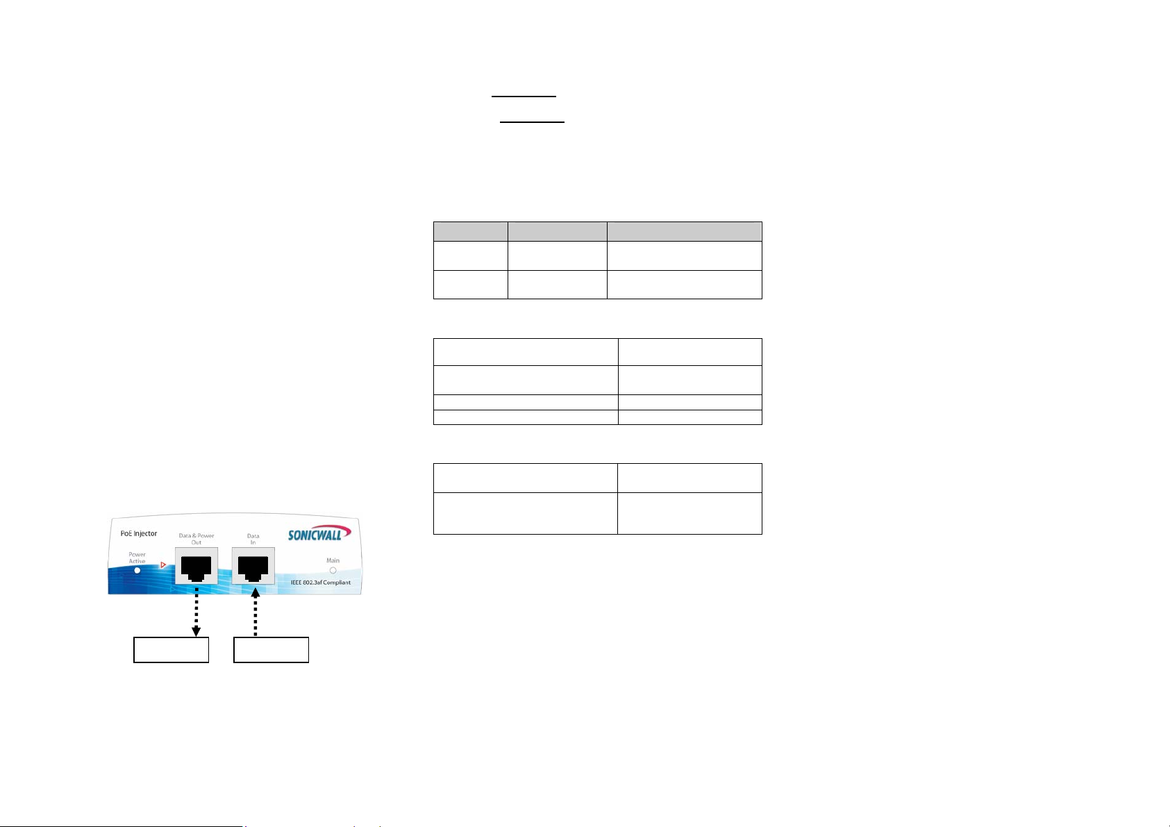
• Connect the unit Data In jack (input) to the Ethernet network
and the Data & Power Out jack (output) to the terminal.
Figure 1: Illustration of connectivity for the PoE Injector.
NOTE: There is no “on-off” switch. Simply plug the PoE
Injector into an AC power source.
Terminal Ethernet
Port Input Power Output
Indicators
steady green -Led Active
(Power is active).
. indicates that the power is onsteady green - Led Main
terminal is connected indicates that the
Specifications
Environmental Specifications
Mode Temperature Humidity
Operating 0 to 50 °C
32 to 122°F
Storage -20 to 70 °C
-4 to 158°F
Electrical Specifications
Input Voltage 90 to 264 VAC
Input Current at 110 VAC
Input Current at 220 VAC
Minimum Available Output Power 15.4 Watts
Nominal Output Voltage 45 to 56 VDC
Ethernet Interface
Input (Data In):
Ethernet 10/100Base-T
Output (Data & Power Out):
Ethernet 10/100Base-T, plus
48 VDC
10 to 90%
(no condensation allowed)
10 to 90%
(no condensation allowed)
(47-63 Hz)
0.34 ampere (max)
0.17 ampere (max)
RJ 45 female socket
RJ 45 female socket, with
DC voltage on wire pairs
7-8 and 4-5.
Troubleshooting Tips
• Be sure AC power is applied to the PoE Injector, using
• Use standard 4 pair (8 wires) UTP or FTP CAT5 cable.
• Do not use a “crossover” type Ethernet cable.
• Be sure the input Ethernet cable is connected to the
• Be sure the output Ethernet cable is connected to the
• Verify that the Ethernet cable length is less than 333 feet
• Verify that a power-ready Ethernet compatible device is
• Verify that the cables and RJ-45 connectors have a tight
Safety Information
Important Safety Information
• Installation and removal of the PoE Injector must be
AC Power Cord Set:
• The power cord must have regulatory agency
• The power cord must be a three-conductor
• The power cord must be rated for a minimum
• The AC wall socket-outlet must be near the PoE Injector
• The PoE Injector data and data/power interfaces are
an operational AC cable with an appropriate ground
connection.
Data In port.
Data & Power Out port.
(100 meters) from the Ethernet source to the load.
connected.
connection and there is not a “short” over the cables or
connectors.
carried out by qualified personnel only.
approval for the specific country in which it is
used (i.e., UL, CSA, VDE, etc.).
type (two current carrying conductors; one
ground conductor) terminated on one end by
an IEC 60320 appliance coupler (for
connection to the PoE Injector), and on the
other end by a plug containing a ground
(earthing) contact.
of 250VAC RMS operation, with a minimum
rated current capacity of 5 amps (or a
minimum wire gauge of 18 AWG (0.75mm
Note: PoE Injector units installed in Australia
require power cords with a minimum wire
gauge of 16 AWG (1.0 mm
and easily accessible. You can remove AC power from
the PoE Injector by disconnecting the AC power cord
from either the wall outlet or the PoE Injector coupler.
qualified as SELV (Safety Extra-Low Voltage) circuits
according to IEC 60950. These interfaces can only be
connected to SELV interfaces on other equipment.
2
).
2
).
 Loading...