

Page 1
Architectural Series
™
Installing the Speakers
Architectural Series speakers are installed after the Bracket has been installed into the wall or ceiling and
the area has been drywalled, mudded, painted and completely finished.
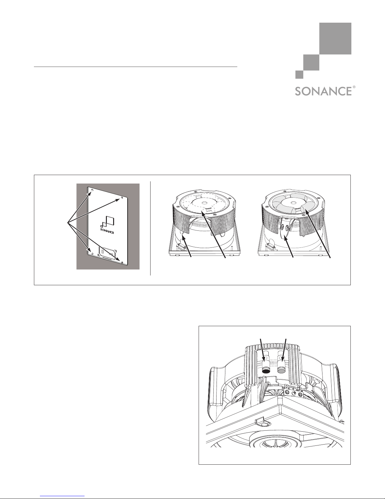
1. Remove the Paint Shield from the Panel Bracket.
• Use a Phillips screwdriver to remove the 4 screws that attach the paint shield to the bracket.
(See
Figure 1
.)
2. FOR ROUND AND SQUARE MODELS ONLY: Remove the packing material around the woofer magnet
at the back of the speaker. Make sure that the pivot tensioner arms are located behind the crossover
cover overhangs (see Figure 2), and make sure that the woofer is facing straight out (not pivoted to
the side). N
OTE: ARCHITECTURAL SERIES WOOFERS DO NOT PIVOT, AND HAVE NO PACKING.
3. Strip ¼” – ½” of insulation from each lead of the
speaker wire. Twist the strands or tin the
exposed wire with solder to ensure that there are
no stray strands. (Stray strands that touch each
other can cause a short-circuit that can damage
your amplifier.)
4. The speaker’s spring-loaded connector posts are
located under the crossover cover (see
Figure 3
).
Push the top of each connector post down to
open the connector and insert the exposed wires
into the holes in the posts.
• The speaker’s positive post is labeled with a
red dot; the negative post is labeled with a
black dot. Double-check that you connected
amplifier “+” to speaker “+” and amplifier “–”
to speaker “–”.
A
RCHITECTURAL SERIES SPEAKER AND WOOFER
INSTALLATION
MANUAL
Page 1 of 4
CORRECT INCORRECT
Tensioner Arms
Behind Cover
Remove
Packin
g
Packing
Material
Tensioner Arms
Ex
p
osed
Figure 2: Positioning the Pivot Tensioners (Round & Square Models Only)
Remove
Screws from
Paint Shield
Figure 1: Removing the Paint Shield
–
+
Figure 3: 6” Series & 4” Series Connection Terminals
Page 2
Architectural Series
™
ARCHITECTURAL SERIES
SPEAKER AND WOOFER
INSTALLATION MANUAL
If a Retrofit Backbox has been installed on the Bracket, connect the marked set of wires inside the
Backbox to the speaker’s connector posts. Connect the red wire to the speaker’s ”+” post and the black
wire to the speaker’s “–” post.
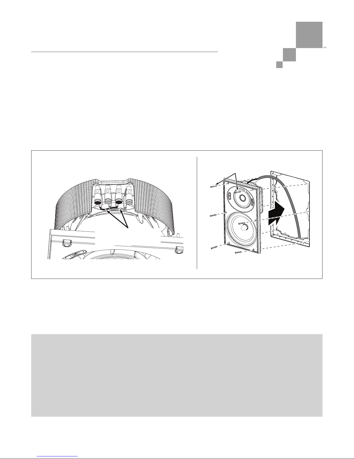
Note: Z8-series and X8-series speakers have two sets of “+” and “–” terminals (see Figure 4).
For single-wire connections you can use either set of terminals. You can also bi-wire these
speakers by removing the jumpers between the LF and MF/HF “+” and “–” terminals, and
connecting two sets of speaker wires from the amplifier, one to each set of terminals.
5. Insert the speaker into the Bracket and use the supplied hex-head screws and supplied hand-held hex
wrench to secure it (see
Figure 5
).
• Round, square and smaller rectangular models require 3 or 4 screws; larger rectangular models
require 6 screws.
• When you notice resistance on the screws the speaker has been clamped successfully.
Page 2 of 4
VERY IMPORTANT:
UUssee OONNLLYY tt hh ee ssuupp pplliieedd hhaa nn dd-- hh ee ll dd hh ee xx wwrr ee nn cchh ttoo aa tttt aacchh tthhee ss pp ee aakk ee rr ..
DDOO NNOOTT UUSS EE AANN EELL EE CCTT RR IICC SSCCRREEWWDD RRII VV EER
R OO RR DDRRII LL LL ..
NNEE VVEERR oovv ee rr -- tt iigghh tt ee nn tt hh ee ss ppeeaakk ee rr mmoo uu nn ttiinngg sscc rree ww ss .. OOvv ee rr -- ttiigghh tt ee nn ii nngg tthhee
ss ccrreewwss ccaann ffrraa cctt uu rr ee
tt hh ee bb rr aacc kkee tt aa ss ss ee mm bbll yy ((ww hhiicc hh hhaa ss bb ee ee nn pp eerr mmaa nn ee nn ttllyy
ii nn ss ttaall llee dd ii nn ttoo tthh ee wwaall ll oo rr ccee iillii nn gg)) .. TT hh iiss ttyy pp ee oo ff d
daamm aa gg ee iiss NN OOTT cc oovv ee rr ee dd bb yy
tthhee AA rrcc hh ii tteecc ttuurr aa ll SS ee rr iiee ss PPaann ee ll BB rraacc kkeett WWaa rr rr aanntt yy ..
Bi-Wiring:
Single-Wiring:
HF/MID
– +
Use Either Set
Remove Both Jumper
Wires When Bi-Wiring
LF
–
+
Figure 4: Z8-Series & X8-Series Connection Terminals
Supplied
Hex-Head Screws
Figure 5: Attaching the Speaker
Page 3

Architectural Series
™
ARCHITECTURAL SERIES
SPEAKER AND WOOFER
INSTALLATION MANUAL
Adjustments
Pivoting Drivers
All Architectural Series speakers
(except Architectural Series Woofers)
have pivoting drivers that allow you
to direct sound towards the listening
area. This will help the sound from
the speakers blend into a solid soundstage even if the speakers are widely
separated.
• All Z/X8 series models have a
pivoting Sonic Eye
®
midrange/
tweeter assembly; round and
square Z/X8 models also have a
pivoting woofer assembly.
• All Z/X6 and Z/X4 series models
have pivoting tweeters; round and
square Z/X6 models also have pivoting woofer assemblies.
To pivot the drivers, apply light pressure to the specific locations shown in
Figure 6
. Do not touch or apply
pressure to the rubber driver surrounds or the driver surfaces.
Midrange and Tweeter Level Controls
All Z/X8-series, all Z/X6-series and the Z/X4 model speakers have a tweeter level control switch;
all Z8 and X8-series speakers also have a midrange level control switch. (Note: Architectural Series
Woofers have no level controls.) These controls let you boost or cut the driver’s level by 3dB to better
match the listening room or the listener’s personal taste. The controls are located on the speaker baffles
(on Fascia models they are located behind the removable fascia). See
Figure 7
.
Page 3 of 4
Press Here
To Pivot Woofer
Press Here
To Pivot Tweeter
Press Here
To Pivot SonicEye
®
Figure 6: Pivoting the Drivers
Midrange
Control
Midrange
Control
Tweeter
Control
Tweeter
Control
Midrange
Control
Tweete
r
Control
R
OUND AND SQUARE MODELS
R
ECTANGULAR MODELS
F
ASCIA MODELS
Figure 7: Midrange and Tweeter Level Controls
Page 4

SONANCE • 212 Avenida Fabricante • San Clemente, CA 92672-7531 • USA
800.582.7777 or 949.492.7777 • FAX: 949.361.5151 • Technical Support: 800.582.0772
www.sonance.com
©2007 Sonance. All rights reserved.
Sonance, Architectural Series and SonicEye are trademarks or registered trademarks of Dana Innovations.
Due to continuous product improvement, all specifications are subject to change without notice.
For the latest Sonance product specification information visit our website: www.sonance.com
33-4414 12/07
 Loading...