

Page 1
MAG6.1 SYSTEM
INSTRUCTION MANUAL
Scan QR Code
for product
installation video
Page 2

TABLE OF CONTENTS
Introduction 3
Box Contents 3
Speaker Layout Planning 3
Types of Wire 4
Speaker Installation 4
Connecting the Speakers 4
Recommended Tools 5
Speaker Wire Connection 5
Connecting the Speaker
Using a 2-Conductor Wire or
Low Voltage Lighting Wire 6
Subwoofer Speaker Wire Connection 7
Specifications 7
Warranty 8
2
Page 3
Introduction
Thank you for purchasing the MAG6.1 SYSTEM. When
properly installed, this system will provide you with years
of outdoor entertainment pleasure. To get the most out
of your new system, please read this manual thoroughly
before you begin installation.
Box Contents
MAG6.1 SYSTEM box contains:
(6) Satellite speakers
(6) Removeable speaker stakes
with 1/2” NPS threading
(16) Silicone filled wire nuts
(1) In-Ground subwoofer
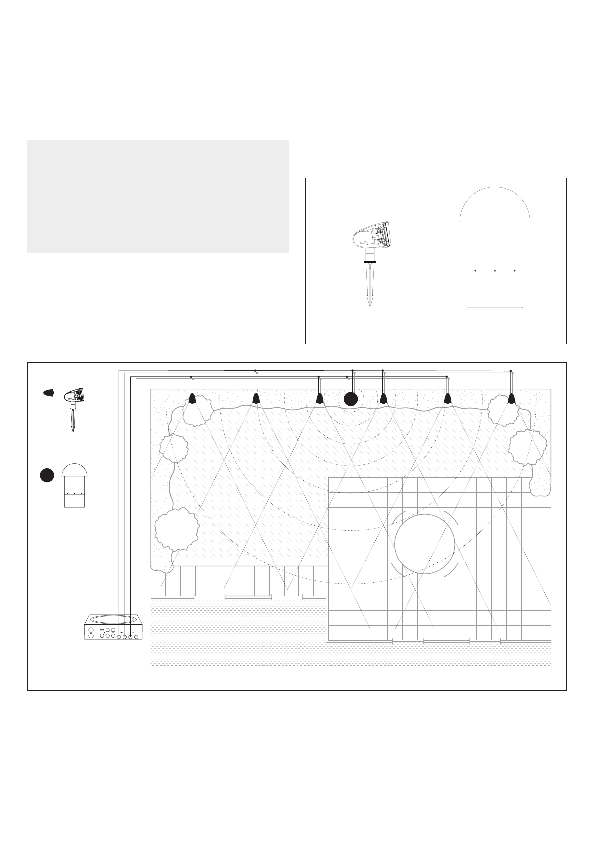
Speaker Layout Planning
The MAG6.1 SYSTEM is designed to deliver a seamless,
evenly dispersed sound field in an ‘open air’ environment.
A daisy chain of multiple satellite speakers and a
subwoofer should be strategically placed to create even,
balanced coverage, minimizing ‘hot spots’ and ‘dead zones’
around the outdoor entertainment area (see Figure 1).
The satellite speakers should be placed from 8 to 10 feet
(2.4 - 3.1 meters) apart for best coverage. To achieve the
best balance between the satellites and subwoofer, the
subwoofer should be placed as close to the center of the
satellites as possible.
If more bass is required, placing the subwoofer near a wall
or other solid structure will greatly reinforce the low bass
frequencies. In some cases you may want to place the
subwoofer closer to your primary listening position.
MAG6.1 SAT
Satellite Speaker
MAG6.1 SUB
In-Ground Subwoofer
Red (+)
Black (-)
Green (-)
White (+)
SAT
LEFT
Subwoofer Bottom Amp Plate
SAT
RIGHT
SAT
LEFT
Figure 2 shows the controls and connections located on
the subwoofer bottom amp plate.
LEFT
RIGHT
Figure 1: Wiring Diagram
SUB
&
SAT
RIGHT
SAT
LEFT
SAT
RIGHT
3
Page 4

Types of Wire
Color-coded, 14/4 direct-burial speaker wire
is recommended.
NOTE: PLEASE REFER TO THE WIRING CHART
BELOW TO DETERMINE WHICH SIZE WIRE TO USE
OVER A GIVEN DISTANCE. DISTANCES LISTED ARE
FROM THE AMP TO THE FURTHEST SPEAKER.
WIRE GAUGE CHART
Wire Gauge
18 Gauge
16 Gauge
14 Gauge
Up to 100 feet (30 meters)
Up to 150 feet (45 meters)
Up to 250 feet (80 meters)
DISTANCE
4. Once the speakers and subwoofer are laid out in
their locations and the wiring is completed per this
installation guide, stake or mount the speakers into
their final locations and bury the subwoofer in its
final location.
NOTE: THE SUBWOOFER REQUIRES A BURIAL SPACE
THAT IS ABOUT 12” DIAMETER AND 11” DEEP. WHEN
THE SUBWOOFER IS IN THE GROUND, ENSURE THAT
THERE IS ROUGHLY 5” OF EXPOSED SUBWOOFER
ENCLOSURE FROM THE SURFACE OF THE GROUND TO
THE BOTTOM EDGE OF THE CANOPY. SEE FIGURE 2.
5” (127mm)
BEST PRACTICE: ‘14/4’ REFERS TO 14 GAUGE,
4-CONDUCTOR WIRE. IT IS IMPORTANT TO USE ONLY
‘DIRECT BURIAL’ WIRE TO MAINTAIN LONG-TERM
SIGNAL INTEGRITY AND PREVENT CORROSION.
USING INDIVIDUAL CONDUCTORS WITH DIFFERENT
COLORS MAKES IT EASYTO IDENTIFY AND ACCESS
BOTH AMPLIFIER CHANNELS. LOW VOLTAGE LIGHTING
WIRE CAN ALSO BE USED BUT IS ONLY SOLD AS A 2
CONDUCTOR WIRE. IF USING A 2 CONDUCTOR WIRE,
THEN RUN TWO PAIRS OF WIRES; ONE FOR EACH
AMPLIFIER CHANNEL (RIGHT/LEFT).
Speaker Installation
1. Place the 6 satellites and 1 subwoofer in their
approximate final locations.
2. Dig a trench 4” to 5” deep to run the speaker wires in.
Be sure to check local building codes for any
trenching limitations.
3. Run your speaker wire through the trench from the
amp to the last speaker location.
SONOS AMP
11” (280mm)
12” (305mm)
Figure 2
Connecting the Speakers
The MAG6.1 SYSTEM allows the satellite speakers to be
wired together in a parallel/daisy chain configuration.
Once you have designated the first speaker as either
left or right, continue alternating the wires between the
left and right channels creating a daisy chain of stereo
satellites (see Figure 3).
NOTE: THE SUBWOOFER CAN BE CONNECTED AT
ANY POINT IN THE DAISY CHAIN.
Red (+)
Black (-)
Green (-)
White (+)
Left and Right
Left
Right
Left
Figure 3: MAG6.1 SYSTEM Wiring Diagram
4
LeftRight
Right
Page 5

Recommended Tools
Wire Stripper
accommodates up to a 12 gauge wire
Speaker Wire Connection
Connecting the speakers using 14/4 direct burial
speaker wire.
1. Pull the 14/4 wire on the spool to the furthest speaker
location. Leave the wire attached to the spool until the
last speaker has been connected.
2. Starting at the last speaker and every speaker that
follows, create a loop of wire approximately 6” in length.
3. Use the round cable stripper to remove the outside
protective wire jacket to expose the 4 individual
color-coded wires. If you are unfamiliar with using a
round cable stripper, please go to YouTube and search
for videos on ‘Using a Round Cable Stripper’. Or visit
the specific brand of cable stripper’s company
website for detailed instructions.
Round Cable Stripper
needed when using 14/4 direct burial wire
Wire Ties and Electrical Tape
4. Use a wire tie to keep the wire loop intact and act as a
strain relief.
PLEASE NOTE: REGARDING THE 4 COLORED WIRES,
THE RED (+) AND BLACK (-) ARE USED FOR THE
RIGHT CHANNEL, WHITE (+) AND GREEN (-) FOR
THE LEFT CHANNEL.
5. Cutting the wires. In this example, we want the first
speaker to be connected to the right channel so we cut
the red (+) and black (-) wires only. Leave the white and
green wires intact.
5
Page 6

6. Strip o 3/4 inch of insulation on the red and black
wires to expose the copper conductor. Combine and
twist the red wires from the amplifier, the first satellite
and the wire running to the next speaker in a
clock-wise motion.
7. Secure these three wires using the provided silicone
filled wire nuts, ensuring that NO COPPER is exposed.
Connecting the Speakers Using a
2-Conductor Wire or Low Voltage
Lighting Wire
1. Pull the first pair of 2-conductor wire to the furthest
speaker location, leaving it connected to the spool near
the amplifier.
2. Starting at the furthest speaker and every other speaker
that follows, create a loop of wire approximately 6”
in length, securing the loop with a wire tie.
To speaker
To next speakerFrom amp
8. Wrap the wire nut and surrounding wire connection in
electrical tape to protect from moisture.
9. At the next speaker, repeat steps 2 – 8 for the left
channel using the white (+) and green (-) leaving the
red (+) and black (-) wires intact.
10. Continue the above steps for the remaining satellite
speakers in the daisy-chain.
IMPORTANT: BE SURE ONLY 3 SATELLITE SPEAKERS
ARE CONNECTED TO EACH AMP CHANNEL;
MIS-WIRING MAY RESULT IN AN UNACCEPTABLE
LOAD WHICH COULD DAMAGE YOUR AMPLIFIER.
3. Cut the wire at the last speaker location in the
daisy-chain closest to the amplifier.
4. Take the spool back to the starting point and pull a
second 2-conductor wire to the furthest speaker
location and repeat steps 1 and 2 (see Figure 4).
5. Starting with the first speaker, cut the wire loop.
NOTE: IF NOT USING COLOR-CODED WIRE, NOTICE
THAT ONE OF THE WIRES OUT OF THE PAIR WILL
HAVE A DIFFERENT TEXTURE OR PRINTING ON IT.
THIS WILL HELP IDENTIFY AND SEPARATE THE (+)
FROM THE (-). FOR SIMPLICITY, USE THE WIRE WITH
TEXTURE OR WRITING AS THE (+) AND THE OTHER
AS THE (-). USE THIS POLARITY STANDARD WHEN
CONNECTING ALL THE SPEAKERS.
6. Strip the insulation on each wire to expose
approximately 3/4” of copper. Combine and twist all
the positive (+) wires together in a clockwise motion.
Repeat this step for all the negative (-) wires.
7. Secure the three wires together using the provided
silicone filled wire nuts ensuring that NO COPPER
is exposed.
8. Wrap the wire nut and surrounding wire connection in
electrical tape to protect from moisture.
9. Repeat steps 5– 8 for the remainder of the speakers.
6
Page 7

Subwoofer Wire Connection
The subwoofer features a dual voice coil driver with 4
wires, one pair for each of the amplifier channels. red
(+) and black (-) are used for the right channel, white
(+) and green (-) for the Left channel. The subwoofer
can be connected at any point along the daisy chain e.g.
beginning, middle, end or anywhere in-between. However,
locating the subwoofer mid-way in the daisy chain will
produce an equal amount of bass for the speakers on either
side of the sub. The subwoofer needs to be connected in
the same manner as the satellites speakers (see Figure 4).
NOTE: THE SONOS AMP FEATURES A SUBWOOFER
RCA OUTPUT THAT IS NOT USED IN THIS APPLICATION.
THE MAG6.1 SUBWOOFER IS DESIGNED TO BE WIRED
IN LINE WITH THE MAG6.1 SATELLITE SPEAKERS.
Left Channel
Right Channel
White
Wires
Green
Wires
Red
Wires
Black
Wires
IMPORTANT: THE SUBWOOFER HAS DUAL VOICE
COILS, ONE FOR THE LEFT CHANNEL AND ONE
FOR THE RIGHT CHANNEL, IT IS CRITICAL THAT THE
POSITIVE AND NEGATIVE WIRES BE CONNECTED
CORRECTLY FOR BOTH CHANNELS. IF EITHER
CHANNEL IS CONNECTED INCORRECTLY NO LOW
FREQUENCY SOUND WILL BE PRODUCED.
Turn your SONOS AMP on and test the system with your
favorite music. If the speakers are operating properly, refill
the wire trench and enjoy your new MAG6.1 SYSTEM.
Specifications
MAG6.1 SYSTEM
(1X) Woofer:
(6X) Satellite:
Frequency Response:
Impedance:
Dispersion
Power Handling:
Sensitivity:
Enclosure Material:
Crossover:
Shipping Weight:
Satellite Dimensions:
Subwoofer Dimensions:
Included Accessories:
8” (203mm) dual voice coil, polypropylene cone & Santoprene™ surround
3 1/2” (89mm) anodized aluminum cone & Santoprene™ surround
40Hz - 20kHz +/-3dB
5 ohms per channel nominal
60º dispersion with an optimum listening area 8’-20’ (2.4-6.1 meters) from the satellites
50 watts minimum; 150 watts system
85dB and 89dB SPL, satellite and subwoofer respectively, 2.83V / 1 meter
Satellites and Woofer - Non-corroding, high-heat ABS enclosures
100Hz
75 lbs (34kg) each
6.75” L x 4.53” Dia. (184mm x 115mm)
21.4” L x 12.4” Dia. (544mm x 315mm)
6 ground stakes, 16 silicone filled wire nuts
FROM AMP AND SPEAKERS
Figure 4
IMPORTANT: BE SURE NOT TO LET ANY STRAY ’+’
AND ’-’ STRANDS TOUCH EACH OTHER. TOUCHING
STRANDS WILL CAUSE A SHORT-CIRCUIT WHICH
COULD DAMAGE YOUR AMPLIFIER.
TO ADDITIONAL SPEAKERS
Installation Best Practice Placement Recommendations:
Satellites:
Woofer:
Listening Area:
Wire Recommendations:
Specifications subject to change. Direct burial cable required (sold separately).
CAD files available for download at www.sonance.com
8’-10’ (2.4-3 meters) apart along perimeter of listening area.
The center of the four satellites.
Up to 1,500 square feet.
18 gauge up to 100’ (33 meters) 4 conductor, stranded, direct burial
16 gauge up to 150’ (50 meters) 4 conductor, stranded, direct burial
14 gauge up to 250’ (80 meters) 4 conductor, stranded, direct burial
7
Page 8

LIMITED ONE (1) YEAR WARRANTY
Sonance warrants to the first end-user purchaser that this Sonance-brand product (“Product”), when purchased from
an authorized Sonance Dealer/Distributor, will be free from defective workmanship and materials for the period stated
below. Sonance will at its option and expense during the warranty period, either repair the defect or replace the Product
with a new or remanufactured Product or a reasonable equivalent.
EXCLUSIONS
TO THE EXTENT PERMITTED BY LAW, THE WARRANTY SET FORTH ABOVE IS IN LIEU OF, AND EXCLUSIVE OF,
ALL OTHER WARRANTIES, EXPRESS OR IMPLIED, AND IS THE SOLE AND EXCLUSIVE WARRANTY PROVIDED
BY SONANCE. ALL OTHER EXPRESS AND IMPLIED WARRANTIES, INCLUDING THE IMPLIED WARRANTIES OF
MERCHANTABILITY, IMPLIED WARRANTY OF FITNESS FOR USE, AND IMPLIED WARRANTY OF FITNESS FOR A
PARTICULAR PURPOSE ARE SPECIFICALLY EXCLUDED.
No one is authorized to make or modify any warranties on behalf of Sonance. The warranty stated above is the sole and
exclusive remedy and Sonance’s performance shall constitute full and final satisfaction of all obligations, liabilities and
claims with respect to the Product.
IN ANY EVENT, SONANCE SHALL NOT BE LIABLE FOR CONSEQUENTIAL, INCIDENTAL, ECONOMIC, PROPERTY,
BODILY INJURY, OR PERSONAL INJURY DAMAGES ARISING FROM THE PRODUCT, ANY BREACH OF THIS WARRANTY
OR OTHERWISE.
This warranty statement gives you specific legal rights, and you may have other rights which vary from state to state.
Some states do not allow the exclusion of implied warranties or limitations of remedies, so the above exclusions and
limitations may not apply. If your state does not allow disclaimer of implied warranties, the duration of such implied
warranties is limited to period of Sonance’s express warranty.
Your Product Model & Description: MAG6.1 - Outdoor Streaming Sound System Powered by Sonos
Warranty period for this Product: One (1) year from the date on the original sales receipt or invoice or other satisfactory
proof of purchase.
ADDITIONAL LIMITATIONS AND EXCLUSIONS FROM WARRANTY COVERAGE
The warranty described above is non-transferable, applies only to the initial installation of the Product, does not include
installation of any repaired or replaced Product, does not include damage to allied or associated equipment which
may result for any reason from use with this Product, and does not include labor or parts caused by accident, disaster,
negligence, improper installation, misuse (e.g. overdriving the amplifier or speaker, excessive heat or cold or humidity,
outdoor installation), or from service or repair which has not been authorized by Sonance.
OBTAINING AUTHORIZED SERVICE
To qualify for the warranty, you must contact your authorized Sonance Dealer/Installer or call Sonance Customer Service
at (949) 492-7777 within the warranty period, must obtain a return merchandise authorization number (RMA), and must
deliver the Product to Sonance shipping prepaid during the warranty period, together with the original sales receipt, or
invoice or other satisfactory proof of purchase.
©2020 Sonance. All rights reserved.
Due to continuous product improvement, all features and specifications are subject to change without notice.
For the latest Sonance product specification information visit our website: www.sonance.com
SONANCE • 991 Calle Amanecer • San Clemente, CA 92673 USA
(949) 492-7777 • FAX: (949) 361-5151 • Technical Support: (949) 492-7777
www.sonance.com
8
02.02.21
 Loading...