

Page 1
INTRODUCTION
PN. 33-2855
I N S T A L L A T I O N I N S T R U C T I O N S
SONANCE SYMPHONY EXTREME T
2 - CHANNEL AUDIO PLACEMENT
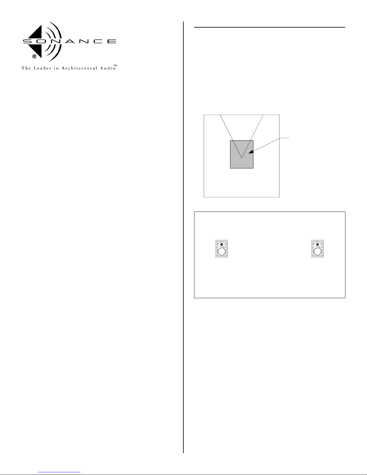
For best performance, the center of the Sonance Symphony Extreme
XT speakers should be placed around ear level. This would be
approximately 40" for a seated listener and 62" for a standing listener.
The distance from the listener to the speakers and the distance
between the speakers should be the same, see diagram. Distance A, B
and C should be the same.
Thank you for purchasing Sonance Symphony Extreme T in-wall
speakers. When properly installed, this product will provide you with
years of entertainment pleasure.
To obtain the full potential of your new speakers, please read all
instructions before starting the installation. If you do not have the
necessary skills to install the speakers yourself, contact your authorized
Sonance dealer for installation options.
PARTS LIST
Each Extreme T speaker package includes the following items:
(2) Sonance Extreme XT speakers
(2) Paintable grilles
(2) Plastic paint plugs to protect speakers during painting
(1) Mounting cutout template ( in packaging )
OPTIONAL ACCESSORIES
New Construction Bracket - part number 90-0700
Plastic template to reserve hole in new construction.
A
CB
Ideal Listening Zone
FlexBracket - part number 90-1193
Plastic template to reserve hole in new construction.
Designed to be used with the FlexbarJ mounting system.
Staple Template - part number 90-0651
Thin plastic template for new construction to reserve hole in
new construction. Designed to be used with the FlexbarJ
mounting system.
Coverplate - part number 90-0693
Designed to cover hole made by FlexBracket, New
Construction Bracket or Staple Template until the speaker is
installed.
Acoustic Enclosure - part number 91687
A 3/4" medium density fiberboard enclosure designed
specifically for the C and Symphony series speakers.
Fire Rate Back Can - part number 91709
A metal can designed for the C and Symphony series
speakers that meets the following fire testing criteria;
ASTM E119, CAN/ULC S101, NFPA 251, UBC 7-1, UL 263.
ENVIRONMENTAL SPECIFICATIONS
Maximum Heat
104 degrees C = (220.0 degrees Fahrenheit)
Maximum Cold
-40 degrees C = (-40.0 degrees Fahrenheit)
Maximum Humidity and Temperature
99% humidity @ 49 degrees C = (120.0 degrees Fahrenheit)
95% humidity @ -40 degrees C = (-40.0 degrees Fahrenheit)
The Extreme speakers meet or exceed the following:
Salt Spray - ASTM-B117
UV Test - ASTM-G23H
IEC / CEE Water Splashing Test - IP-X4
Vibration Test - ASTM D5112-98 and ASTM D3580-95
1
Page 2
WIRE GAUGE AND QUALITY
The total wire resistance should be less than 10% of the speaker
impedance. If using an 8 ohm speaker, your total wire resistance
should be no more than 0.8 ohms.
In simple terms, the extra resistance from the wire will have a very
negative effect on the sound quality of the speaker. The sound can be
less dynamic, definition of bass frequencies can be reduced, and in
extreme cases, the high frequencies can be attenuated. Amplifier
power is also wasted in the wire, reducing the maximum output level
of the system.
Please refer to the following chart when deciding on the appropriate
wire gauge for your installation.
Wire resistance in Ohms vs. length of cable run
Distance in Feet
20 gauge
18 gauge
16 gauge
14 gauge
12 gauge
10 gauge
50' 100' 150' 200' 250' 300'
5.18
4.32
3.45
1.73
1.30
.85
.54
.34
.22
2.59
1.94
1.28
.81
.51
.33
2.59
1.71
1.08
.68
.44
3.24
2.14
1.35
.85
.56
3.89
2.56
1.62
1.02
.67
.86
.65
.43
.27
.17
.11
PREPARING THE INSTALLATION LOCATION
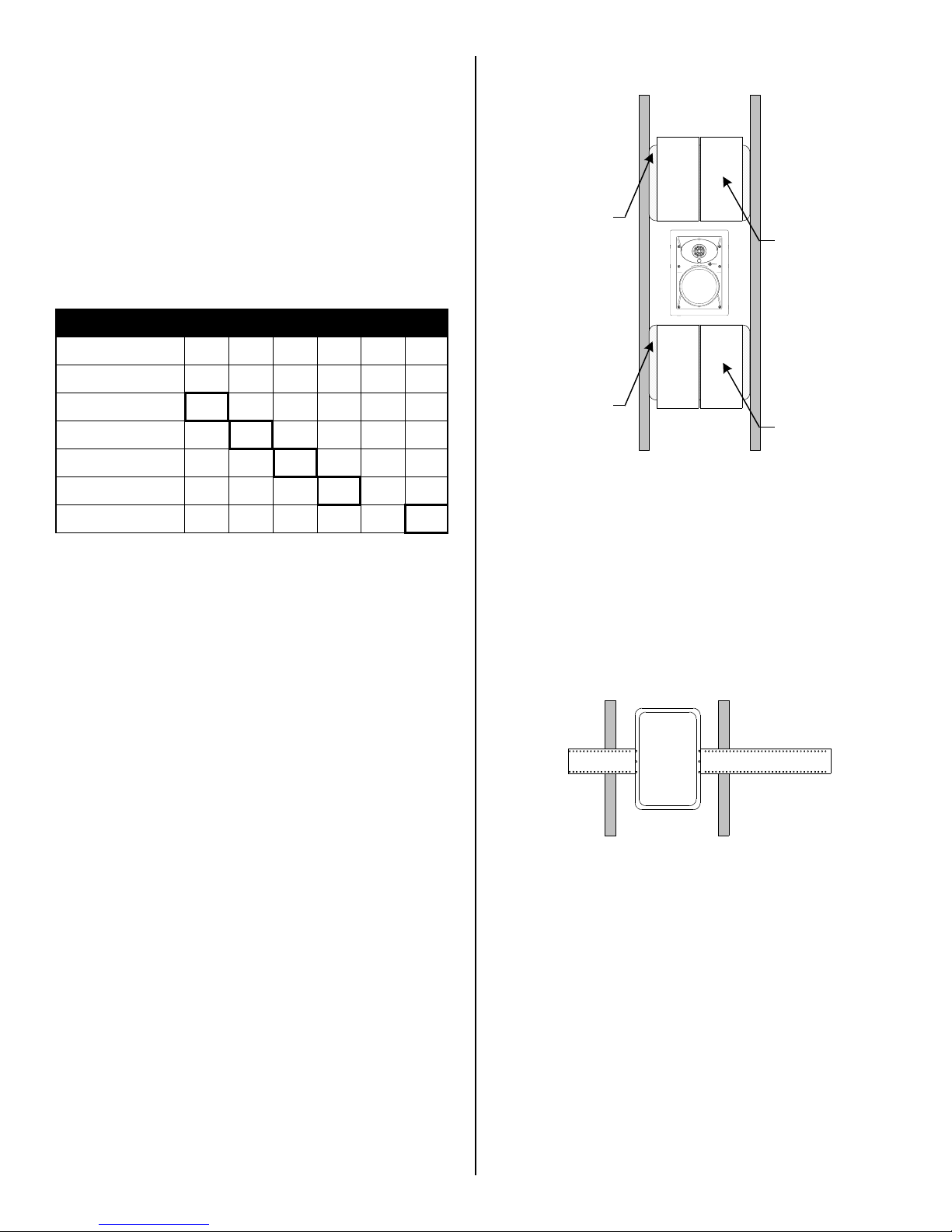
Acoustic Pillow
Damping Tiles
Acoustic Pillow
Damping Tiles
The Sonafill System
New Construction
The Extreme XT speakers feature an integral Rotolock mounting
system for quick mounting into walls. The Symphony / C series
FlexBracket and New Construction Bracket are only necessary in new
construction installations when reserving a location for the speaker is
desired.
All Sonance speakers are designed to be relatively insensitive to
changes in enclosure volume. To achieve the ultimate performance
from the Extreme XT speakers, a section of the stud bay can be
sectioned off to form a back box. Building this enclosure will create a
dramatic improvement in the quality of bass response and power
handling.
Back box volume requirements:
Insulating the wall cavity
Speaker performance can be enhanced by insulating the cavity with
fiberglass insulation.
When installing speakers in a wall, it is best to insert a sheet of
unfaced fiberglass insulation above and below the speaker.
To further improve the sound quality, install insulation in the bays
adjacent to the speaker location. This will reduce noise produced by
the unsupported drywall.
Sonafill
Sonafill is a retrofitable acoustical treatment for loudspeakers that
virtually eliminates the noise produced by resonating drywall and
dramatically improves mid-bass sound quality. Sonafill also reduces
room-to-room noise especially in multi-channel installations where
many speakers are installed.
The Sonafill system consists of two pillows and four tiles. Installation is
accomplished by first adhering the tiles to the inside of the cavity, then
stuffing the two pillows in place behind the tiles.
Extreme XT 1.00 cubic feet (28.3 liters)
®
The FlexBracket and New Construction Bracket will serve as a guide for
the drywaller when cutting holes for in-wall speakers. The FlexBracket
or New Construction Bracket is nailed or screwed to the studs so that
the hole is in the desired location once the drywall is installed.
Symphony / C series FlexBracket
Retrofit
With the Flexbar system, the speaker can be installed directly into
existing walls. Once the hole is cut and the cable is run, the speakers
can be installed in a matter of seconds.
Once you have determined the area you would like to locate your
speakers, you will need to do an obstruction survey. Before you cut the
hole for the speaker, be certain no studs, conduit, pipe, heating duct
or air return will interfere with the speaker.
The cutout for the Extreme XT is 6 3/4" (171mm) x 11" (279mm).
There must also be 2-1/2" (63.5mm) of depth within the wall for the
speaker.
A cut out template is provided in the packaging of the speaker.
Position the template where the speaker is to be located and pencil an
outline on the wall. If you are unsure about obstructions, drill a small
hole in the center of the cutout and insert a coat hanger into the hole
to feel for possible obstructions. If no obstructions are found, proceed
with cutting the hole using a drywall saw and run the speaker wires.
2
Page 3

INSTALLING THE SPEAKERS
Step 1
Remove the paint plug from the
speaker. Attach the wire from your
amplifier to the terminals on the back of
the speaker. Double check the polarity
of the speaker wires, amplifier + to
speaker + and amplifier - to speaker -.
Proper polarity is critical in home theater
installations.
Step 2
Make sure the Roto-Lock clamps are in
the full clockwise position so that all the
clamps are tucked within the cutout
border. Insert the speaker into the hole
in the ceiling.
Note: The maximum clamp thickness is
1-1/4" (32mm). The minimum clamping
thickness is 1/8" (3.2mm)
Step 3
Tighten the six screws on the front of
the baffle. The Roto-Lock clamps will
rotate into position automatically and
begin clamping. When you notice
resistance on the four screws, the
speaker has been clamped successfully.
The flange is designed to flex and
conform to any small imperfections in
the wall surface. The screws should not
be tightened so far that the flange bows
out.
Step 4
After the speaker is installed, the grille
can be installed. Insert about half of the
grille into the groove at the edge of the
speaker. Gently fit the remaining half of
the grill into the speaker by working
your hands around the speaker fitting
the grille into the groove as you go
along.
PAINTING THE SPEAKERS AND GRILLES
Speakers and grilles can be painted before installation, which will
eliminate the "paint scar" if the speaker needs to be removed for
service. Speakers may also be painted after installation, but before the
grilles are attached. All speakers come from the factory fitted with a
plastic "paint plug." Use the paint plug to protect the drivers while the
flange is being painted with the wall.
Sonance suggests always painting the grilles separate from the
speaker. The grilles may be lightly sprayed with thin paint (5 parts
thinning agent to 1 part paint), but be careful not to plug the holes.
Too much paint will adversely affect the sound of the speaker.
Once the grilles and flange are painted and dry, remove the paint plug
from the flange and install the grilles.
Note: The torque applied to the
mounting screws can be adjusted for
proper grille fit.
3
Page 4

TECHNICAL ASSISTANCE AND SERVICE
Extreme XT
Tweeter 1.0" (25mm) Polyurethane dome
Woofer 6-1/2" (165mm) Black anodized aluminum cone with a
Frequency Response 55Hz - 20kHz + 3dB
Impedance 8 ohms nominal - 6 ohms minimum
Power Handling 5 - 60 Watts
SPL 89 dB
Grille Powder coated Stainless steel
Dimensions WxHxD 8-1/8" (206mm) x 12-3/16" (310mm) x 2-1/2" (63.5mm)
Cutout Dims WxH 6-3/4" (171mm) x 10-7/8" (276mm)
Shipping Weight 9 lbs (4.1 KG) per pair
rubber surround
The Technical Assistance Department at Sonance is available at (800)
582-0772 or (949) 492-7777 to answer any questions concerning the
operation and installation of your speakers between the hours of 7:00
AM and 5:00 PM Pacific time, Monday through Friday, except holidays.
In the event your unit should need repair or service, you may return
the unit to your authorized dealer or use the following guidelines:
1. Be prepared to state the model number and / or serial number,
date of purchase and dealer's name and address when calling.
2. Contact Sonance directly at (800) 582-0772 or (949) 492-7777 or
at www.sonance.com
3. If you are returning the product directly to Sonance, call us to
obtain a return authorization number before shipping. YOU MUST
HAVE PRIOR AUTHORIZATION TO RETURN YOUR UNIT.
4. The original packaging must be used. If the original packaging is
unavailable, replacements can be obtained from Sonance for a
small fee.
5. Ship the product via United Parcel Service, Federal Express, or
RPS. Please do not use the U.S. Mail service.
6. Write the return authorization number on the outside of the box.
7. Ship to:
Attn: Quality Assurance Department
Sonance
212 Avenida Fabricante
San Clemente, CA 92672-7531
8. FREIGHT COLLECT SHIPMENTS WILL BE REFUSED !
WARRANTY COVERAGE ( U.S. ONLY )
If, within five (5) years from the date shown on the bill of sale, the unit
fails due to a defect in workmanship or material, Sonance will, at its
option and at no charge, repair or replace the components of such unit
which prove to be defective. For this warranty to be effective, the bill
of sale must show that the unit was purchased from an "Authorized
Sonance Dealer". This warranty shall apply exclusively to the original
purchaser and shall not apply to units purchased for industrial or
commercial use.
Furthermore, this warranty shall not apply if:
1. Damage to the unit was caused by accident, abuse or misuse;
2. The unit was opened, modified, or repaired by unauthorized
personnel.
3. The unit was not used as outlined in the operating instructions.
EXCLUSIONS AND LIMITATIONS
The warranty set forth above is in lieu of all other warranties,
expressed or implied, of merchantability, fitness for a particular
purpose, or otherwise. The warranty is limited to Sonance products
registered herein and specifically excludes any damage to loudspeakers
and other allied or associated equipment which may result for any
reason from use with this product. Sonance shall in no event be liable
for incidental or consequential damages arising from any breach of this
warranty or otherwise. This warranty gives you specific legal rights,
and you may have rights which vary from state to state.
Sonance $ 212 Avenida Fabricante $ San Clemente, CA 92672-7531, USA $ (800) 582-7777 or (949)492-7777 $ FAX: (949) 361-5151 $ Technical Support: (800) 582-0772
c
2003 Sonance. Sonance , Roto-Lock, and Sonafill are trademarks of Sonance.
www.sonance.com
 Loading...