

SOMFY 5058465B Installation And Operating Manual
Somfy.com
RS485 4 ILT Interface
Installation and Operating guide
Guida all’installazione e di funzionamento
Montage- und Gebrauchsanleitung
Notice d’installation et d’utilisation
Ref : 5058465B
ENITDEFR

2 Copyright © 2008 Somfy SAS. All rights reserved - V0 - 09/2008
SAFETY AND IMPORTANT INFORMATION
• This Somfy product must be installed by a professional motorisation and home automation installer, for whom these instructions are intended.
• Before installation, check that this product is compatible with the associated equipment
and accessories.
• These instructions describe how to install, commission and use this product.
• Moreover, the installer must comply with current standards and legislation in the country
in which the product is being installed, and inform his customers of the operating and
maintenance conditions for the product.
• Any use outside the sphere of application specied by Somfy is not approved. Such use,
or any failure to comply with the instructions given herein will invalidate the warranty, and
Somfy refuses to accept liability.
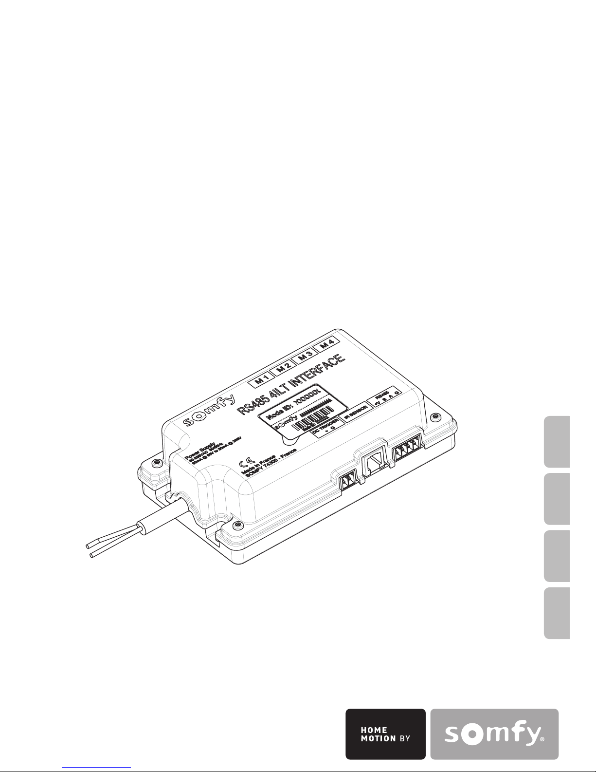
PRODUCT DESCRIPTION
The RS485 4ILT Interface is a motor controller for multi ratio motorized projection screens
designed to be integrated into the projection screen cases.
It can control up to 4 SOMFY ILT motors.
It can be interfaced with universal infra red remote controls, a RS485 data line or a video-
projector through a trigger.
ENVIRONMENT
Damaged electric products and batteries should not be disposed of with normal household waste.
Make sure to drop them in specially provided containers or at an authorized organization
that will ensure they are recycled.
3Copyright © 2008 Somfy SAS. All rights reserved - V0 - 09/2008
INSTALLATION
WIRING
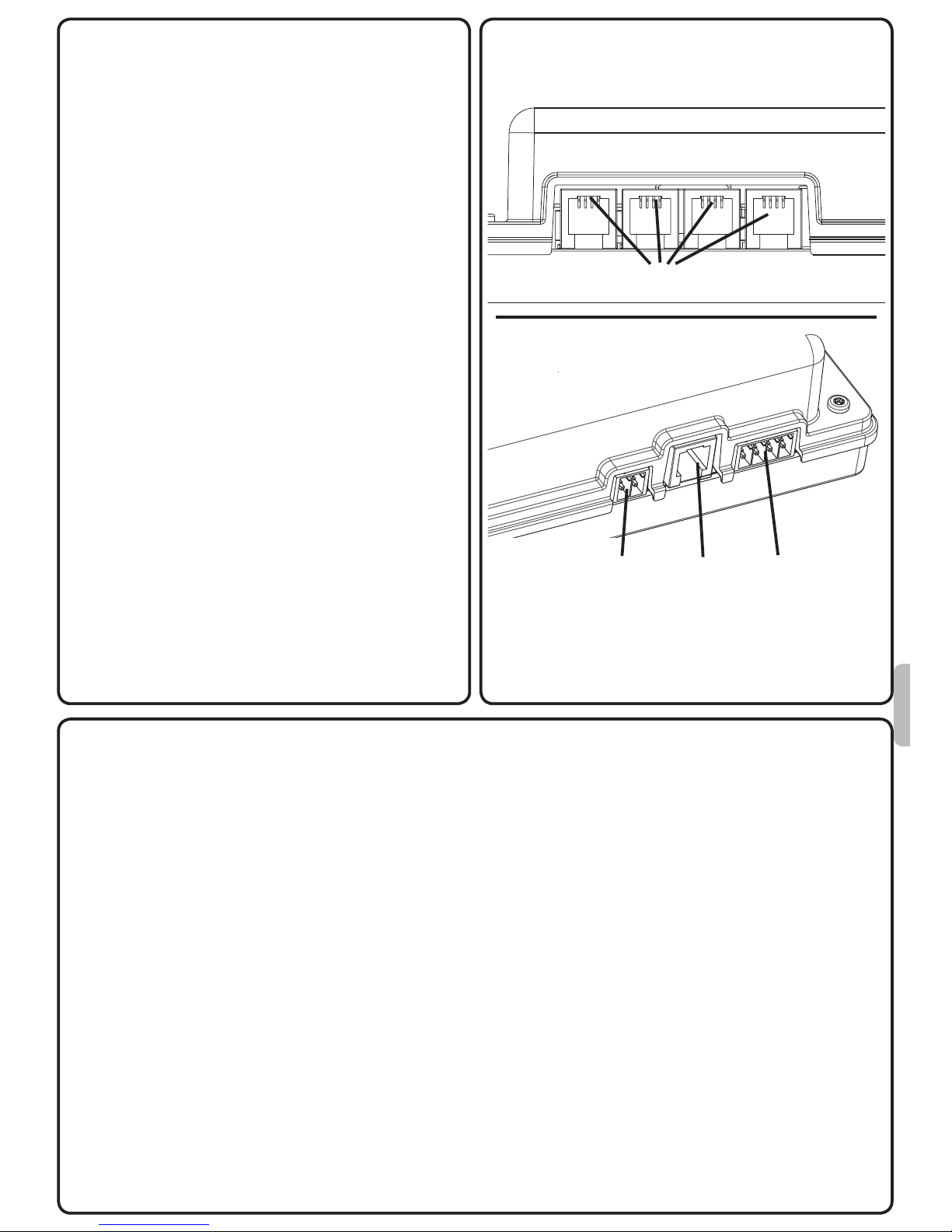
Motor wiring
1) 4xILT plugs (plug directly the ILT motor
to the RJ9 plug).
Controls wiring
1) Trigger (For videoprojector)
● + : 5 → 30V
● G : Ground
2) IR (Use a Somfy IR sensor)
3) RS485:
● +V: Not connected
● B: RS 485 B
● A: RS 485 A
● G: Ground
Power wiring
Connect the interface to a standard AC
power source
1
1
3
2
COMMISSIONING
Commissioning must be performed with a Somfy 8 channels IR remote control
prior to any use.
ILT motors will not react to any control as long as they are not set.
To set ILT motors, please refer to MOTOR SETTING.
ILT motors may have been already set prior to this installation by the means of a
dedicated setting tool by the manufacturer.
If more than one motor only is connected to the interface, you need to set each
motor separately before setting the differents formats.
By default, all motors connected to the interface will react together to any operation.
To select a motor, please refer to : MOTOR SELECTION
4 Copyright © 2008 Somfy SAS. All rights reserved - V0 - 09/2008
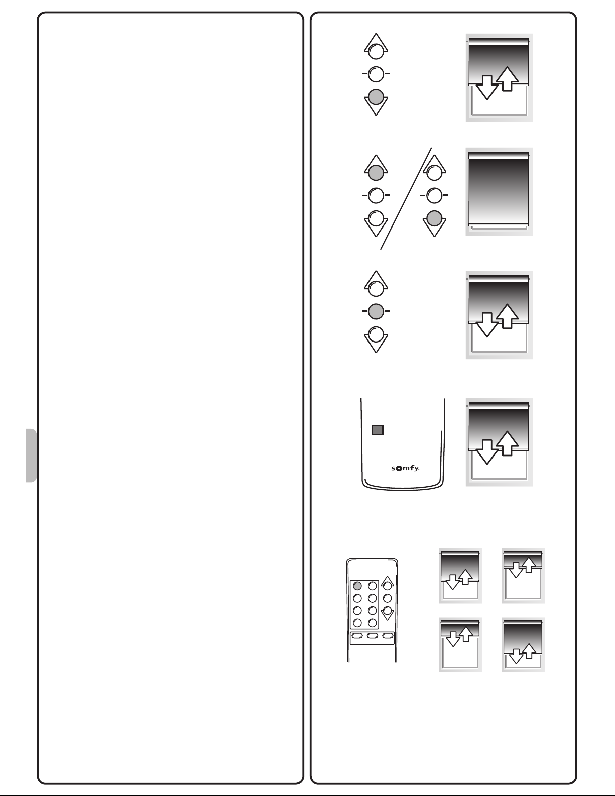
MOTOR SELECTION
Use the 1→8 or 5→8 button to select one
of the motors. The selected motor will
acknowledge by doing a small jog.
1) The 1→8 button to select the previous
motor.
2) The 5→8 button to select the next motor.
3) The 1→4 button to select all the motors
connected to the interface.
Once a motor is selected, you can control
it individually.
After 2 min without any operation, all motors will react again to any operation.
MOTOR SETTING
A) SETTING MODE
To enter in setting mode, press the prog
button of the remote control until the
screen jogs.
1 - 8 1 - 45 - 8
1 - 8 1 - 45 - 8
1 - 8 1 - 45 - 8
1
3
2
12
34
56
78
1 - 8 1 - 45 - 8
5Copyright © 2008 Somfy SAS. All rights reserved - V0 - 09/2008
B1
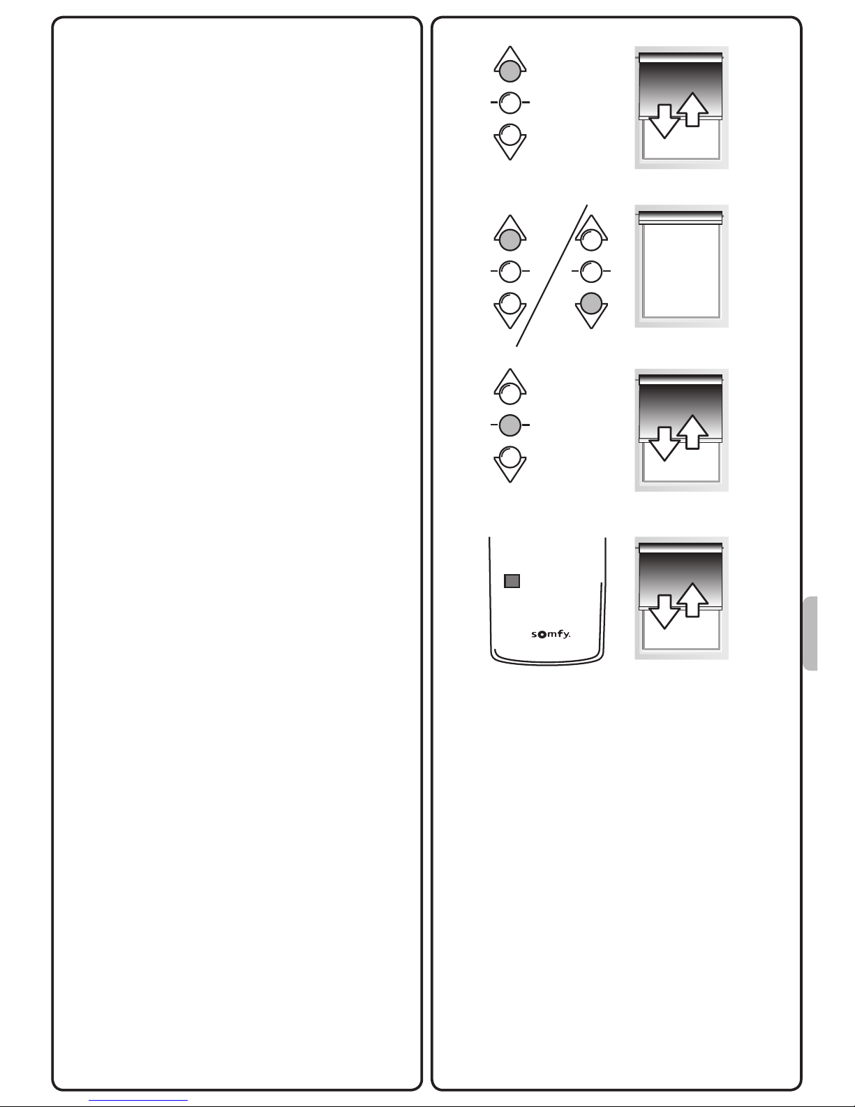
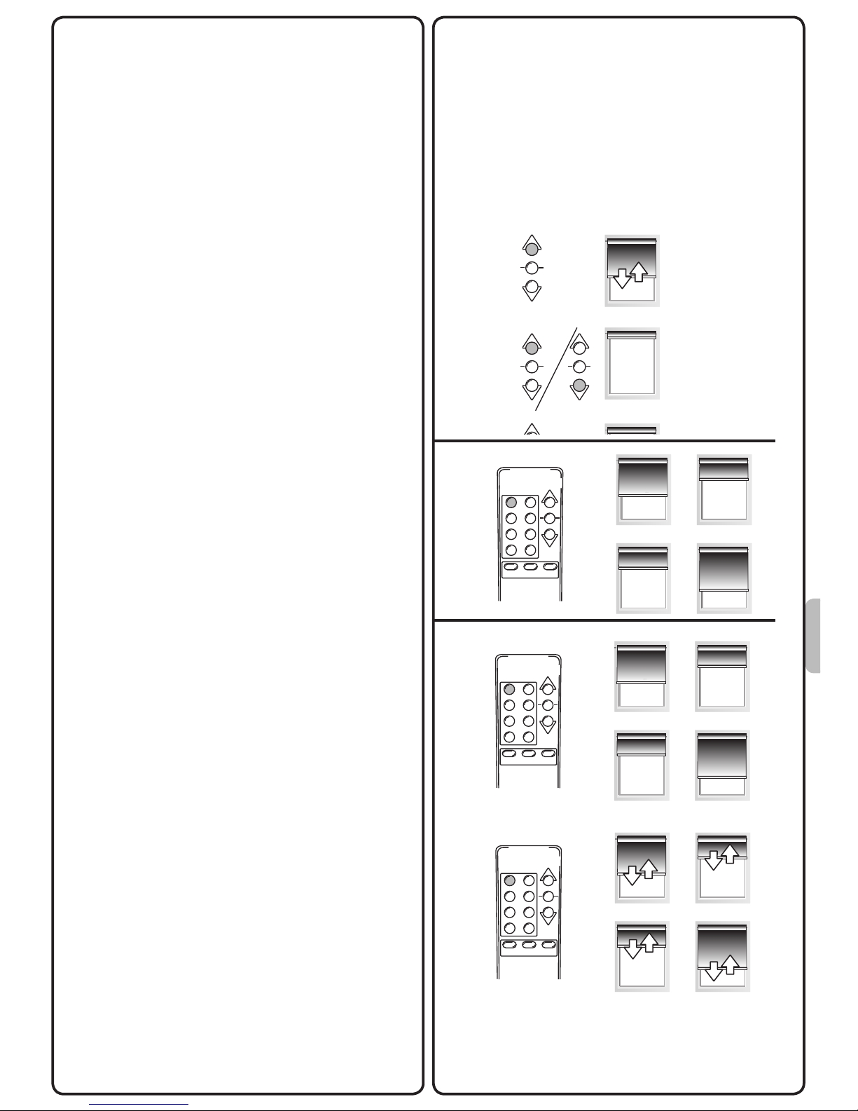
B) ADJUSTING THE END LIMITS
B1) UP end limit
Press the UP button until the motor jogs.
With the UP or DOWN buttons, move the
screen to the desired up limit.
If the direction of rotation is not correct,
press the STOP button until the screen
jogs.
Press the prog button to conrm the limit
until the motor jogs.
PROG.
6 Copyright © 2008 Somfy SAS. All rights reserved - V0 - 09/2008
B2) DOWN end limit
Press the DOWN button until the motor
jogs.
With the UP or DOWN buttons, move the
screen to the desired down limit.
If the direction of rotation is not correct,
press the STOP button until the screen
jogs.
Press the prog button to conrm the limit
until the motor jogs.
C) FORMAT SETTING
Buttons 1 to 8 will be used to set 1 to 8
formats.
By default, buttons 1 to 7 are not set,
button 8 stands for the user Home Position
(all the screens retracted).
It can be changed by setting a new format
or deleting this format.
To set a format, put one by one each
screen to the desired positon, then press
the selected button (eg : button1) until all
the screens jog.
During the adjusment of the screen, if you
press and hold the UP or DOWN button,
the screen moves step by step.
You can use this function for a better adjustement of the screen.
12
34
56
78
1 - 8 1 - 45 - 8
PROG.
PROG.
B2
C
7Copyright © 2008 Somfy SAS. All rights reserved - V0 - 09/2008
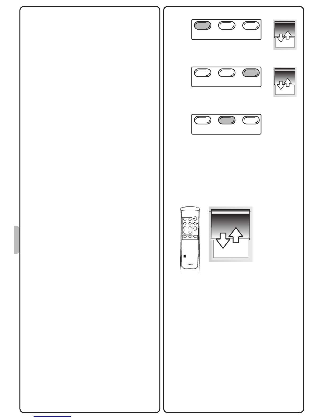
USE
With an IR remote control
By default, all motors connected to the
interface will react together to any opera-
tion.To move individually a motor, please
refer to MOTOR SELECTION.
A) UP, DOWN and STOP
1) To move the screen, press briey the
UP or DOWN button.
2) To stop the screen, press the STOP
button.
B) READJUSTING THE END LIMIT(S)
You need to readjust both end limits.
Please refer to : ADJUSTING THE END
LIMITS
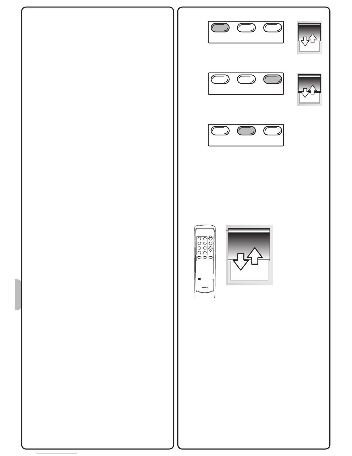
C) CALL A FORMAT.
To call a format, press on the desired
format button.
D) READJUSTING A FORMAT
Please refer to : FORMAT SETTING
E) DELETE A FORMAT.
Press the format button corresponding
to the format to delete.The screens go to
the memorized position.
Press the corresponding format button
until all the screens jog. The format is
deleted.
A1
A2
C
E
12
34
56
78
1 - 8 1 - 45 - 8
12
34
56
78
1 - 8 1 - 45 - 8
12
34
56
78
1 - 8 1 - 45 - 8

8 Copyright © 2008 Somfy SAS. All rights reserved - V0 - 09/2008
With an universal IR remote control
- Please refer to the universal IR remote control instructions to learn the codes from a
Somfy 8 channels remote control to the universal IR remote control.
- If there is no specic instructions, please contact your Somfy local retailer.
With a trigger input
- The trigger input allows to synchronize the motorized projection screen with a videoprojector (For videoprojector with DC12V output).
- When the videoprojector will be powered ON, the interface will put the projection screen
in Format 1 position.
- When the videoprojector will be powered OFF, the interface will put the projection screen
in Format 8 position.
With a RS485 data line
The appendix (cf page 34) describes the SOMFY RS485 protocol, which is used to
communicate with the RS485 4ILT Interface.
The RS485 protocol supports bi-directional communication between a host and the
interface.
The term «Host» refers to the device initiating communication with the interface, usually a
computer-based system.
9Copyright © 2008 Somfy SAS. All rights reserved - V0 - 09/2008
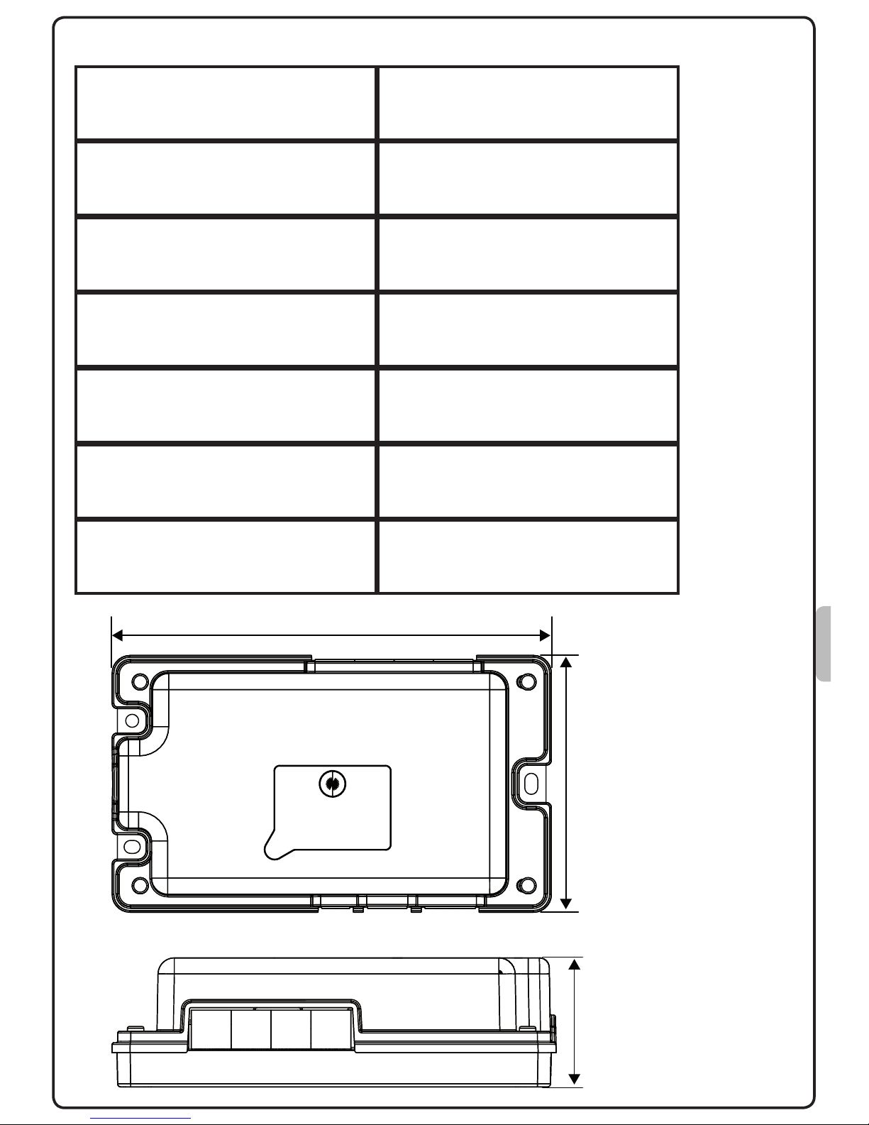
TECHNICAL DATA
137 mm
80 mm
40 mm
Voltage
Operating temperature
Protection rating
Max number of motors
Control
90V → 255V
0°C / 60 °C
IP20
4
IR / RS485
Frequency 50Hz → 60Hz
Trigger Input 0V → 30V

10 Copyright © 2008 Somfy SAS. All rights reserved - V0 - 09/2008
AVVERTENZE E INFORMAZIONI IMPORTANTI
• Questo prodotto Somfy deve essere installato da un tecnico specializzato nella motorizzazione e nell’automazione di apparecchiature residenziali. Questa guida è destinata solo
a tale installatore.
• Prima di procedere con l’installazione, vericare la compatibilità di questo prodotto con
le apparecchiature e gli accessori installati.
• Il presente manuale descrive l’installazione, la messa in funzione e la modalità di utilizzo
di questo prodotto.
• L’installatore è tenuto a rispettare le normative e la legislazione in vigore nel paese nel
quale viene effettuata l’installazione, e deve informare i suoi clienti sulle condizioni di
utilizzo e di manutenzione del prodotto.
• Ogni utilizzo diverso dall’ambito di applicazione denito da Somfy non è conforme e
comporta, così come il mancato rispetto delle istruzioni riportate nel presente manuale,
l’annullamento della responsabilità e della garanzia Somfy.
DESCRIZIONE DEL PRODOTTO
RS485 4ILT Interface è un’unità di controllo per schermi di proiezione motorizzati multiformato progettata per essere integrata all’interno dei cassonetti.
L’interfaccia è in grado di controllare no a 4 motori ILT SOMFY.
Può essere interfacciata con telecomandi ad infrarossi universali, una linea dati RS485 o
un videoproiettore attraverso un ingresso trigger.
AMBIENTE
I prodotti elettrici danneggiati e le batterie esauste non devono essere smaltiti insieme alla
normale immondizia domestica.
Devono essere smaltiti all’interno di contenitori speciali appositi o portati presso un’orga-
nizzazione autorizzata che ne garantirà il riciclaggio.

11Copyright © 2008 Somfy SAS. All rights reserved - V0 - 09/2008
INSTALLAZIONE
CABLAGGIO
Cablaggio motore
1) 4 connettori ILT (collegare il motore ILT
direttamente al connettore RJ9).
Cablaggio comandi
1) Ingresso trigger (Per videoproiettore)
● +: 5 → 30V
● G: Terra
2) IR (Usare un sensore IR Somfy)
3) RS485:
● +V: Non collegato
● B: RS 485 B
● A: RS 485 A
● G: Terra
Cablaggio di alimentazione
Collegare l’interfaccia a una fonte di
alimentazione standard AC
1
1
3
2
MESSA IN SERVIZIO
La messa in servizio, prima di qualsiasi utilizzo, deve essere effettuata utilizzando
un telecomando IR Somfy a 8 canali.
I motori ILT non reagiranno ad alcun comando nché non saranno stati congurati.
Per congurare i motori ILT, consultare la sezione CONFIGURAZIONE MOTORE.
I motori ILT possono essere già stati congurati dal costruttore prima di questa
installazione usando uno strumento di congurazione dedicato.
Se all’interfaccia sono collegati più di un motore, è necessario congurare ciascun
motore separatamente prima di impostare i diversi formati.
Di default, tutti i motori collegati all’interfaccia reagiranno insieme ad ogni operazione.
Per selezionare un motore, consultare la sezione: SELEZIONE MOTORE
12 Copyright © 2008 Somfy SAS. All rights reserved - V0 - 09/2008
SELEZIONE MOTORE
Usare i tasti 1→8 o 5→8 per selezionare
uno dei motori. Il motore selezionato ese-
guirà un breve movimento di conferma.
1) Il tasto 1→8 per selezionare il motore
precedente.
2) Il tasto 5→8 per selezionare il motore
successivo.
3) Il tasto 1→4 per selezionare tutti i motori
collegati all’interfaccia.
Una volta selezionato un motore, questo
può essere controllato singolarmente.
Trascorsi 2 min. senza che alcuna
operazione venga effettuata, tutti i motori
reagiranno contemporaneamente ad ogni
operazione.
CONFIGURAZIONE MOTORE
A) MODALITÀ CONFIGURAZIONE
Per entrare nella modalità di congurazione, premere il tasto «prog» del telecomando nché lo schermo non esegue un breve
movimento di conferma.
1 - 8 1 - 45 - 8
1 - 8 1 - 45 - 8
1 - 8 1 - 45 - 8
1
3
2
12
34
56
78
1 - 8 1 - 45 - 8
 Loading...