

SOMFY 1841103, Axroll Installation Manual
Radio receiver for rolling garage door
Installation Manual
Powersupply voltage :230Vac 50-60 Hz.
Fuse : 250V 5A with timeout
Max motor power : 230Vac 750W.
Protection rating : IP 55.
Ambient operating T° :-15°C to +55°C.
Radio frequency : 433.42MHz
Accessory power supply : 24Vcc (direct).
Resistance values for resistive sensor
bar : From 5 to 14
KΩ
Maximum current for accessories : 0.33A i.e. 8W max.
(cells, keypads, loops, sensorbar, etc…) or 13W intermittent (orange light
10W + accessories 3W.)
Orange light : 24V, 10W maxor 230V 40W max
Area lighting : 230Vac, 500W.
Auxiliary output : ContactNO, 250Vac 500W.
Operating class :1, the ground must be connected.
150 mm
150 mm
40 mm
=
: Automatic mode
Pressing the remote control opens and closes automatically
after timeout T1 (chapter 3.8).
During closing, pressing the remote control again orthe
detection of an obstacle reopens the door.
=
: Semi-automatic mode
Pressing the control triggers opening or closing. Pressing again
during opening has no effect.
Pressing during closing reopens the door.
=
: Sequence mode
Cyclic operation (up / stop / down / stop...).
Pressing during opening or closing stops without reversion.
=
: Sequential mode + Timeout
Similar to the sequential mode, but with automatic closing aftert
timeout T1 (chapter 3.8).
=
: 3-button mode
This mode is used to set a separate control
foropening, closing, and stopping the
door.
=
: Forced mode with + & - keys on the
keyboard
(default mode)
This mode is used to control the door using the “ + ” and
“ - ” keys on the Axroll box in the endstop adjustment phase.
Press and hold “ + ” to open.
Press and hold “ - ” to close.
GB
3.1 Configuring the operating mode: parameter (plant value = 05)
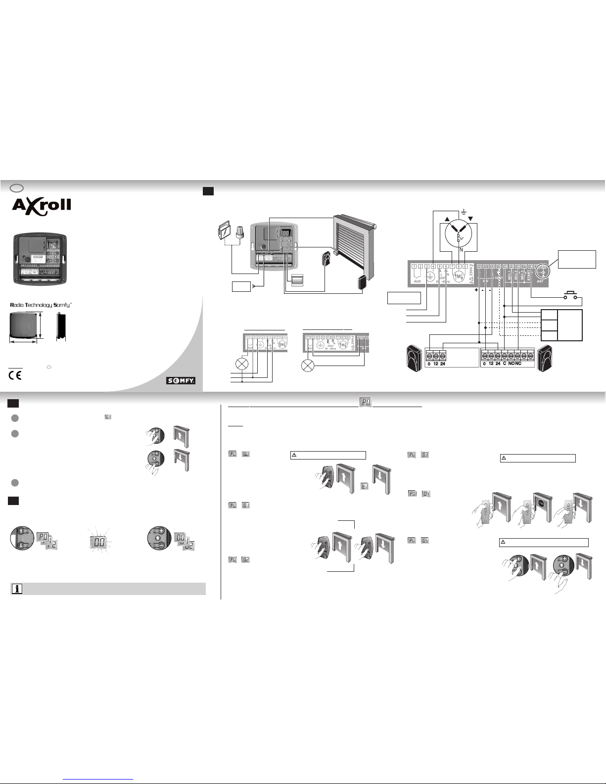
The cross-section of the wires is given for information.
The AXROLL recei ver is used to control a rolling garage door fitted with
a 230V motor with built-in endstops using Keytis 2/4 RTS, Telis1/4 RTS,
and Inis RT transmitters.
Different safety and signaling systems can be connected to the AXROLL
(sensor bar, photocells, flashlights, area lighting).
Ref.N1841017B V1
SOMFY SAS, capital 20 000 000 Euros, RCSBonneville 303 970 230
in this mode, the safety devices are deactivated
Mandatory installation of safety accessories
Mandatory installation of safety accessories
lighting or
signaling
chapter 3.7
Pushbutton
sensor bar
photocells
MAINS
230V - 50Hz
2 x 0.75 mm
2
2 x 0.75 mm
2
4 x 0.75 mm
2
2 x 0.75 mm
2
2 x 0.75 mm
2
4 x 0.75 mm
2
3 x 1.5 mm
2
Certain operating modes impose connecting safety accessories (NF EN 12453). Non compliance with these rules can lead to a facility
h
azardous for its users.
The Axroll has six operating modes:
Configuration
Use the “ + “ or“ - “ keys to change the value of the
parameter.
The last value is recorded automatically (the display is
fixed when pressing the keys).
1 sec.
Use the “ “ or “ “ keyrs to
browse the menu and display
the parameter required.
One second after releasing the key,
the screen indicates the parameter
value to change.
(display blinks)
The Axroll control boxis fully and easily configured to achieve optimum operation matching the types of accessories connected, as
well as the operation mode required by the user.
The various parameters proposed are notmandatory, and browsing the menus imposes no particular sequence.
Powering on the product: the display indicates the value
Check the motor’s rotation direction using the “ + “ and “ - “ keys.
press and hold the “ + “ key to open the door.
press and hold down the “ - “ key to close the door.
If the operation is reversed, poweroff the product, and revert the motor’s wiring
(terminals 7 and 9).
Referto the motor's installation manual to set the end stop system.
Ground
Phase
Neutral
Motor
Photocells
Ref: 9001000
Pushbutton
Sensor
bar
Test
Supply
Contact
230V - 50Hz
Lighting configuration
Ground
Phase
Neutral
lighting
500W max.
Or
ange light configuration
orange lights.
switch off the mains before any intervention.
use flexible cables.
connect the ground cables.
afterinstallation, no traction must be applied to the
terminal strips.
Apply the electric installation standards, as well as
the following points:
3
Wiring
1
Checking the motor’s rotation direction
2
Motor
Measure the motor operating time using permanentrunning (e.g. 20sec. for rising), then set the T0 parameter (motor operating time,
chapter 3.8) with a value slightly above the time observed (about+3 sec .).
This product complies with the standard “SHousehold and similarelectrical appliances - Safety - Part
2-95: Particular requirements for drives for vertically moving garage doors for residential use” IEC
60335-2-95.
This contributes to implementing installations complying with the standard “safety in using motorised
doors” NF EN 12453. Axroll must be installed inside the garage with a motorequipped by a manual
override system.
To return to the men u, press the “ “ or “ “ keys to return to value C1 (or any othervalue indicating the
product’s operation: see § 4) or after a one-minute waiting time.
1
2
3
Pull the antenna wire
through the right-hand
wire grommet.
Hereby, SOMFY, declares thatthis product (AXROLL) is in compliance
with the essential requirements and otherrelevant provisions of
Directive 1999/5/EC.
ADeclaration of Conformity is available at the web address
www
.somfy.comHeading CE.
Usable in EU,
CH
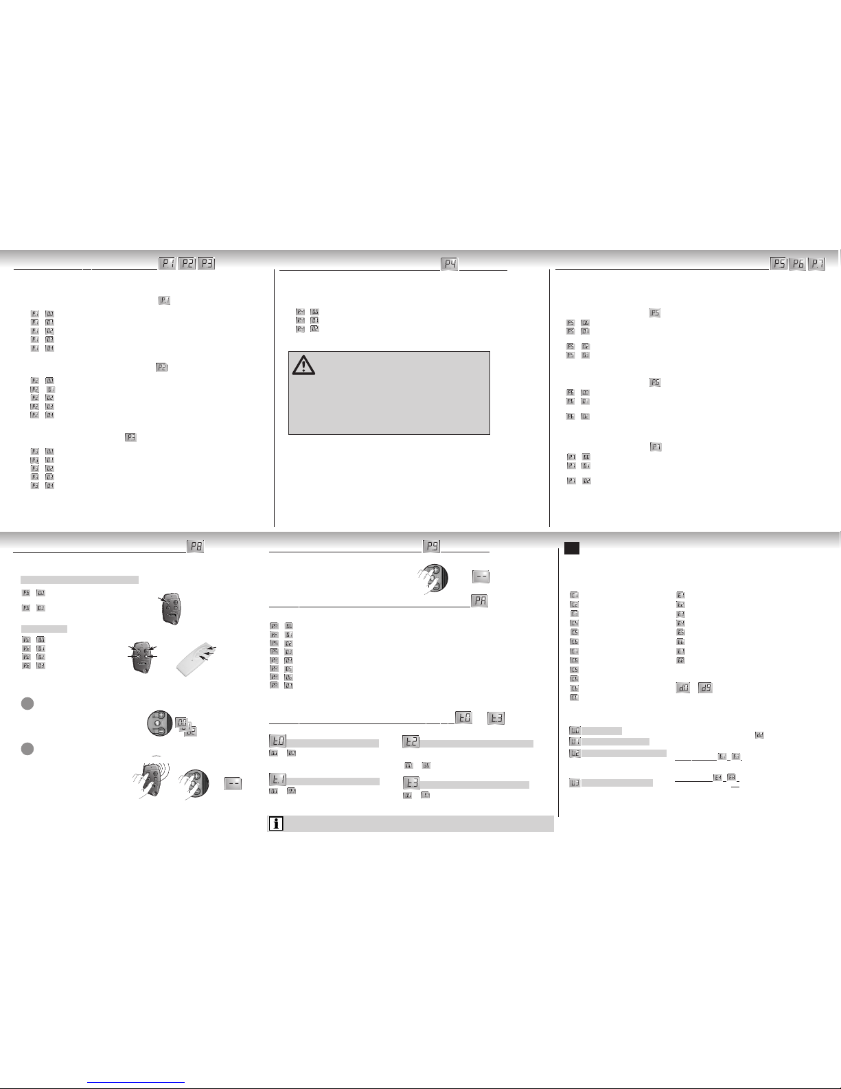
When using a resistive sensor bar, the lattermust be wired onto safety input 1.
The opening safety device stops then recloses partially (non configurable action).
The safety action at opening (P1, P2, or P3 = 01) is not configurable (stopage followed with partial door reopening).
However, safety actions upon closing (P1, P2, orP3 = 02) can be configured:
=
Stop the door.
=
Stop, then total reopening of the door (defaultmode)
=
Stop then partial reopening of the door(2 seconds operation)
The self-test function is used to checkproper operation of the safety accessories automatically at the
end of closing.
CYCLE COUNTERS
EVENT CODES
Axroll waiting fora command
Opening door
Wait before closing the door
Closing door
Open cell hidden
Close cell hidden
ADMAP cell hidden
Door movement forced by keypad
Emergency stop triggered
Self-testing safety
Permanent contact on “START” input
Wait before motorreversion
FAULT CODES
Safety faultat opening (contact always open)
Safety faultat closing (contact always open)
ADMAP safety fault(contact always open)
Self-test failed on safety input1
Self-test failed on safety input2
Self-test failed on safety input3
Intensity exceeded on 24V powersupply (too many accessories connected)
Operating time “T0” too short or motorendstop not reached
Log of the last 10 faults
.... See fault code above.
Reinitialise the Axroll after a fault
To clear the fault codes, select the parameter and press and holding the
“ + ”key for 3 seconds until dashes appear “ -.- ”
F
or the fault codes from to :
Once the fault is corrected, itis not required to clear the fault code of the
log to return to normal operation.
F
or defect codes from to :
Once the fault is corrected, you m
ust clear the defect code for
the log to return to normal operation.
“0” to “99” Watts
* If the connection of accessories matches the diagram in chapter1.
**Area Dangerous forMovement Accessible to the Public.
Motor operating time
(Increment of 1 sec.)
Adjust a time slightly longer than the actual operating time.
Tens and units
Thousands and hundreds
Hundred and tens of thousands
ACCESSORY CONSUMPTION
power consumed in Watts
3.2 Safety input function: parameters
3.3 Safety action upon closing: parameter (plant value = 01)
3.4 Configuration of the self-testing function: parameters
Time for reclosing the door
(Increment of 1 sec.)
Enabled in automatic operating modes (§ 3.1)
Waiting time before motor reversion
Particular case of motors not accepting reversion of the rotation
direction without stopping phase.
(Increment of 1 sec.)
The Axroll can be controlled in the three-button mode using a reverterwith three keys wired onto the START,
SEC2, and SEC3 inputs (if the latter are configured “non wired”: chapter3.2).
Area lighting time after cycle end
(Increment of 1 min.)
+
Clearing all remote controls is performed by pressing and holding for
3 seconds the key “+” until dashes appear “-.-”
3 sec.
3 sec.
long press
Opening
Stop
Closing
According to the type of operation chosen in chapter3.1, the value of the P8 parameter does not
produce the same effects.
Automatic, semi-automatic, or sequence modes.
3-button mode
3.5 Programming remote controls: parameter
3.6 Clearing remote controls: parameter (plant value = 04)
3.7 Configuration of auxiliary accessories: parameter
3.8 Configuring the operating mode: parameters to
=
Opening/Closing Command
(default mode)
.
=
Auxiliary output control
(driving the accessory connected to the AUX output).
=
Open command
=
Close command
=
Stop command
=
Auxiliary output control
(driving the accessory connected to the AUX output).
Press simultaneously the remote control key to
program and the key
“ + “ on the Axroll forthree seconds until
dashes appear “ -.- ”
DIsplay the value of the function to program using
the “ + “ and “ - “ keys on the Axroll.
Choose the remote control key's function to program.
Opening
Stop
Closing
Auxiliary
Opening
Stop
Closing
1
Save the code (Axroll can save maximum 32 channels)
2
Self-testing safety input 1: parameter
(plant value = 00)
=
No self-test of the accessory connected (defaultmode)
=
Self-test for photocells by powersupply cutting.
(caution, the transmitting cell mustbe supplied on terminals 10/12 and the receiver cells on terminals 10/11).
=
Self-test for accessory fitted with a TEST input(cells or sensor bar).
=
Self-test for resistive sensorbar (value comprised between 5 and 14 KΩ ).
Configuration of safety input 1 (sensor bar*): parameter (plant value = 00)
=
No accessories connected to safety input 1 (default mode)
=
Accessory connected to safety input 1 enabled when opening the door
=
Accessory connected to safety input 1 enabled when closing the door
=
ADMAP** safety: active upon closing + forbids starting atopening
=
Contact for connecting an emergency stop device
Configuration of safety input 2 (photocell*): parameter (plant value = 00)
=
No accessories connected to safety input 2 (default mode)
=
Accessory connected to safety input 2 enabled when opening the door
=
Accessory connected to safety input 2 enabled when closing the door
=
ADMAP** safety: active upon closing + forbids starting atopening
=
Contact for connecting an emergency stop device
Configuration of safety input 3: parameter (plant value = 00)
=
No accessories connected to safety input 3 (default mode)
=
Accessory connected to safety input 3 enabled when opening the door
=
Accessory connected to safety input 3 enabled when closing the door
=
ADMAP** safety: active upon closing + forbids starting atopening
=
Contact for connecting an emergency stop device
The auxiliary contact is a dry contact. A single accessory can be connected and power supplied according to the use configured.
=
Contact to drive an electric latch (The latch mustbe supplied with an outside power supply)
=
Contact to drive an electromagnetic latch
=
Contact to drive an Orange flashlightwithout notice (only during the door’s operation)
=
Contact to drive an Orange flashlightwith notice (before starting and during door’s operation)
=
Contact to drive a zone lighting (defaultmode, automatic switch off after timeout T3 § 3.8)
=
Contact to drive an open door indicator
=
Contact of the stable mono relay type to drive an automation system
=
Contact of the bi-stable relay type to drive an automation system
Self-testing safety input 2: parameter
(plant value = 00)
=
No self-test of the accessory connected (defaultmode)
=
Self-test for photocells by powersupply cutting.
(caution, the transmitting cell mustbe supplied on terminals 10/12 and the receiver cells on terminals 10/11).
=
Self-test for accessory fitted with a TEST input(cells or sensor bar).
Self-testing safety input 3: parameter (plant value = 00)
=
No self-test of the accessory connected (defaultmode)
=
Self-test for photocells by powersupply cutting.
(caution, the transmitting cell mustbe supplied on terminals 10/12 and the receiver cells on terminals 10/11).
=
Self-test for accessory fitted with a TEST input(cells or sensor bar).
Operating information
4
safety 1: P1+P5
safety 2: P2+P6
safety 3: P3+P7
Ensure you configure the safety input used for
the appropriate self-test:
Once the safety accessories are connected and the safety inputs configured,
check manually the proper operation of the accessories before the final
start up of the facility.
List of operating information displayed by Axroll used to viewand an easy diagnostic of the facility’s status.
To return to the men u, press the “ “ or “ “ keys to return to value C1 (or any othervalue indicating the product’s
operation: see § 4) or after a one-minute waiting time.
 Loading...