

SOMFY 1810872 Operating Instructions Manual
UNIVERSAL RTS INTERFACE II
Operating Instructions
The addressable Universal RTS Interface II (URTSI II) can be used to communicate
between home automation or other third party systems and SOMFY’s RTS Motors and
controls. It is capable of individual or group control, and can be operated via infrared
remote, RS232 and RS485 serial communication. Once an input is activated, an RTS
radio command is sent to the automated window treatment.
DESCRIPTION
CONNECTION DIAGRAM
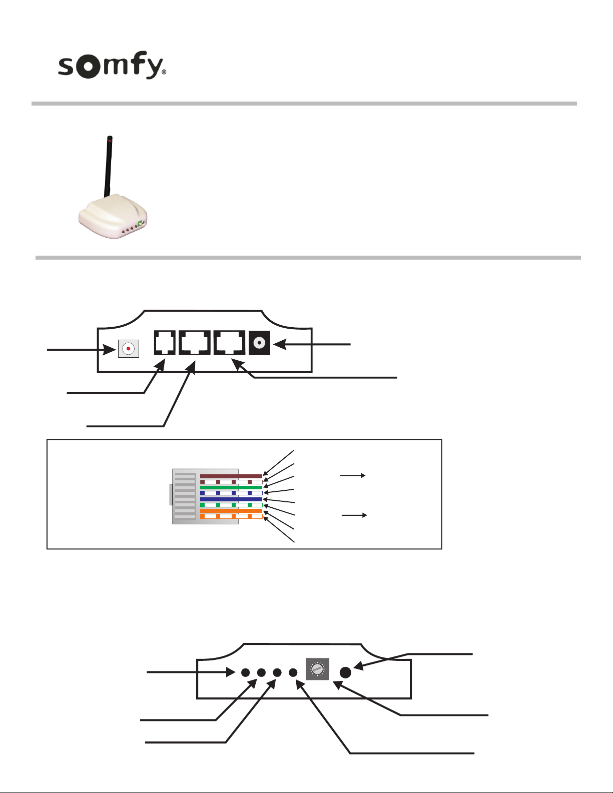
Back of Interface control box
Antenna
IR Sensor Input
RS232 Input
or RS485 Input
RS485 Input/Output
Power
Front of Interface control box
F
0
E
D
C
B
A
9
6
8
7
5
3
4
1
2
UP Button
STOP Button
Power/Transmit LED
URTSI Address or
RTS Channel
Rotary Switch
Program Button
DOWN Button
Part Number: 1810872
* As an option, power to the URTSI II can be
supplied on leads 4 & 5. In this case, the
plug-in transformer is not needed. In addition,
the power can be daisy-chained to the next
URTSI II over the CAT5 cable. The power
supply should be sized based on the number
of Interfaces on the network segment.
NOTE: Do Not remove antenna.
If a new antenna is needed, it
must be ordered from Somfy to
ensure FCC requirements are
maintained.
Pin 8
Pin 1
RS232/RS485 Pin-Out
(Shown Tab-side Down)
RS485 A (+)
Common
RS485 B (-)
RS232 RX
RS232 TX
Bus Power*
Common
Bus Power*
To RS232 TX
To RS232 RX
www.AVOutlet.com - Email: Sales@AVOutlet.com - 1-877-271-5398

A. INITIAL SETUP
1. Connect a 9v DC transformer (included) to the receptacle on the back of the control box. The LED will light green to indicate power.
2. Be careful not to mount or enclose Interface on or in metal, as this may effect radio reception.
3. Set the RTS Receiver or motor into its Programming Mode. Refer to the installation instructions of the relevant RTS receiver or motor for this procedure.
NOTE: for initial programming provide power only to the motor or control being programmed.
4. Using the rotary switch, select the channel to be programmed. Letters A through F stand for channels 10 through 15, 0 for 16. Briefly press the programming button
(1 sec. max), the window treatment will jog to indicate the channel has been memorized.
5. Repeat the steps above for each channel or product to be memorized, up to 16.
6. To test the control operation, simply press the UP, STOP or DOWN buttons on the front of the control. The window treatment should move appropriately. The LED will
flash red to indicate the radio signal has been transmitted.
B. INFRARED OPERATION
1. The RTS Interface is compatible with Somfy’s multichannel transmitter. Connect an infrared sensor to the appropriate connector on the back of the Interface.
2. Each individual motor is activated by first aiming the transmitter at the sensor and pressing the desired unit number on the transmitter and then pressing the UP or
DOWN buttons. Press the center button to STOP the window treatment at any time.
3. The Infrared Channel stays active for 3 minutes. After that, the channel must be reselected.
C. RS232 OPERATION
1. The Somfy RS232 interface uses the following communications settings: 9600 Baud, 8 Data Bits, 1 Stop Bit, No Parity
2. Set the rotary switch to position 1.
3. The basic format for communication is as follows: URTSI ADDR MOTOR CHAN DIR
The URTSI II address is 01.
The motor channel should be 2 digits from 01 to 16.
The directional commands are: U = Up D = Down S = Stop (Must be Capital letters)
4. Examples:
Motor 1 UP: 0101U (TEXT)
Motor 5 DOWN: 0105D
Motor 12 STOP: 0112S
D. RS485 OPERATION
1. The Somfy RS485 interface uses the following communications settings: 9600 Baud, 8 Data Bits, 1 Stop Bit, No Parity
2. With RS485, it is possible to connect 16 Universal RTS Interfaces on one network. Each Interface will have its own address. To select the address, set the
rotary switch to the desired number. Letters A through F stand for addresses 10 through 15, 0 for 16.
3. The basic format for communication is as follows: URTSI ADDR MOTOR CHAN DIR <CR>
The URTSI II address should be 2 digits from 01 to 16.
The motor channel should be 2 digits from 01 to 16.
4. The directional commands are: U = Up D = Down S = Stop (Must be Capital letters)
5. For tilting commands, each increment is approximately 1/10th second of motor movement. The tilt commands are below:
Tilt UP 10 increments: 9 Tilt DOWN 10 increments: <shift>9 [equivalent = (]
Tilt UP 9 increments: 8 Tilt DOWN 9 increments: <shift>8 [equivalent = *]
Tilt UP 8 increments: 7 Tilt DOWN 8 increments: <shift>7 [equivalent = &]
Tilt UP 7 increments: 6 Tilt DOWN 7 increments: <shift>6 [equivalent = ^]
Tilt UP 6 increments: 5 Tilt DOWN 6 increments: <shift>5 [equivalent = %]
Tilt UP 5 increments: 4 Tilt DOWN 5 increments: <shift>4 [equivalent = $]
Tilt UP 4 increments: 3 Tilt DOWN 4 increments: <shift>3 [equivalent = #]
Tilt UP 3 increments: 2 Tilt DOWN 3 increments: <shift>2 [equivalent = @]
Tilt UP 2 increments: 1 Tilt DOWN 2 increments: <shift>1 [equivalent = !]
Tilt UP 1 increment: 0 Tilt DOWN 1 increment: <shift>0 [equivalent = )]
6. A command is available to be used as a delay between successive commands. The format for this is Wx. X is a 1/2 second multiplier. Valid commands are W1 W9 or 1/2 second to 4.5 second delay.
COMMAND EXAMPLES (TEXT)
Unit 1, Motor 3 UP: 0103U<cr>
Unit 2, Motor 10 DOWN: 0210D<cr>
Unit 1, Motor 2, Tilt UP 5 increments: 01025<cr>
Unit 3, Motor 5, Tilt DOWN 6 increments: 0305%<cr>
Unit 1, Motor 3 UP; Wait 1/2sec; Unit 2, Motor 5 Down: 0103;W1;0205D<cr>
Unit 2, Motor 12 Tilt UP 25 increments: 02129;02129;02125<cr>
Unit 3, Motor 11, Tilt DOWN 3 increments; Wait 2sec; Unit 3 Motor 6 UP: 0311@;W4;0306U<cr>
PROGRAMMING NOTES
- The URTSI II can process up to 5 successive commands without needing a WAIT command.
- The URTSI II can process up to 3 movement commands and 2 WAIT commands in a single command line.
- It is mandatory to use the WAIT command when more than one URTSI II are connected together using RS485 communication.
OPERATION
www.AVOutlet.com - Email: Sales@AVOutlet.com - 1-877-271-5398
 Loading...