

SOLIS Solis-3P12K-4G, Solis-3P17K-4G, Solis-3P20K-4G, Solis-3P15K-4G, Solis-3P10K-4G-LV Installation And Operation Manual

Installation and Operation Manual
Solis 4G Three Phase Inverter
(12-20kW)
Ver 1.1
Ginl on g (N ingbo) Technologi es C o. , Ltd.
Ningb o Gi nl on g Techn ol og ie s Co., Ltd.
No. 57 Ji nt on g Ro ad, Binha i In du st rial Pa rk , Xi an gshan, Ni ng bo ,
Zheji an g, 3 15 712, P.R. Ch in a.
Tel: +86 (0 )5 74 6 57 8 1806
Fax: +8 6 (0 )5 74 6 578 1606
If you en co unt er a ny p rob le m on the in ve rte r, pl ea se fi nd o ut the in ve rte r S/ N
and con ta ct us , we w il l try t o re spond t o yo ur qu es ti on ASA P.

2
4
6
6
6
6
6
9
9
13
21
21
21
4
2
3
5
11
22
22
22
…………………………………………………………………………………………………………………………
…………………………………………………………………………………………………………………………
………………………………………………………………………………………………………………………………
………………………………………………………………………………………………………………
…………………………………………………………………………………………………………………………
………………………………………………………………………………………………………………
………………………………………………………………………………………………………………………
………………………………………………………………………………………………………………………………
……………………………………………………………………………………………………………
………………………………………………………………………………………………………
……………………………………………………………………………………………………
………………………………………………………………………………………
……………………………………………………………………………………………………………………………
……………………………………………………………………………………………
………………………………………………………………………………………………………
…………………………………………………………………………………………………………………
…………………………………………………………………………………………………………
……………………………………………………………………………………………………………………………
…………………………………………………………………………………………………………………………
…………………………………………………………………………………………………………………
4
……………………………………………………………………………………………
24
………………………………………………………………………………………………………………………………
24
………………………………………………………………………………………………………………………
27
31
33
35
……………………………………………………………………………………………………………………
…………………………………………………………………………………………………………………
…………………………………………………………………………………………………………………………
………………………………………………………………………………………………………………
7
7
8
…………………………………………………………………………………
………………………………………………………………………………………………………………
……………………………………………………………………………………………………………
1. Introduction
2. Safety Instructions
2.1 Safety Symbols
2.2 General Safety Instructions
2.3 Notice For Use
3. Overview
3.1 Front Panel Display
3.2 LED Status Indicator Lights
3.3 Keypad
3.4 LCD
5. Installation
5.1 Select Location for the Inverter
5.2 Mounting the Inverter
5.3 Electrical Connections
7. Operation
6. Start & Stop
6.1 Start the Inverter
6.2 Stop the Inverter
1.1 Product Description
1.2 Packaging
7.2 Information
7.1 Main Menu
4. Product handing and storage
4.1 Product handling
4.2 Product Storage
7.3 Settings
7.4 Advanced Info.
7.5 Advanced Settings
8. Maintenance
9. Troubleshooting
10. Specifications
……………………………………………………………………………………………………………………………………
Contents
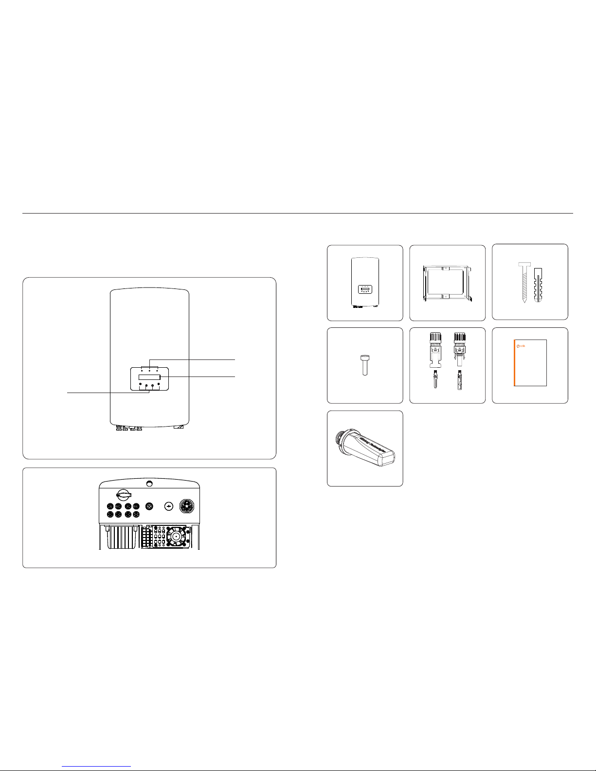
1.1 Pr oduct Desc ripti on
.3..2.
WiF i/GPR S Monit or the ro dsx1
(apole gamy)
LED lights
LCD display
4 buttons
Fig ure 1.1 F ront vi ew
Fig ure 1.2 B ottom v iew
Inv erter x 1
Bac k plate x 1
1.2 Pa ckaging
When you receive the inverter, please ensure that all the parts listed below are included:
Exp ansio n screw x 3
Fas tenin g screw x 2
DC co nnect or
(12K 15Kx3 ,17K2 0Kx4)
Use r manua l x1
Installation and Operation Manual
Solis 4G Three Phase Inverter
(12-20kW)
Ver 1.1
Ginlong (Ningbo) Tech nolog ies Co. , Ltd.
1. Introduction 1. Introduction
If anything is missing, please contact your local Solis distributor.
Sol is 4G thr ee phas e inver ters in tegra te DRM an d backf low pow er cont rol fun ction , that
cou ld suit able fo r smart g rid req uirem ent.
Thr ee phas e 4G seri es inve rter co ntain 5 m odels w hich ar e liste d below :
Sol is-3P 12K-4 G, Soli s-3P1 5K-4G , Solis -3P17 K-4G, S olis- 3P20K -4G
Sol is-3P 10K-4 G-LV
.5..4.
2. Safety Instructions 2. Safety Instructions
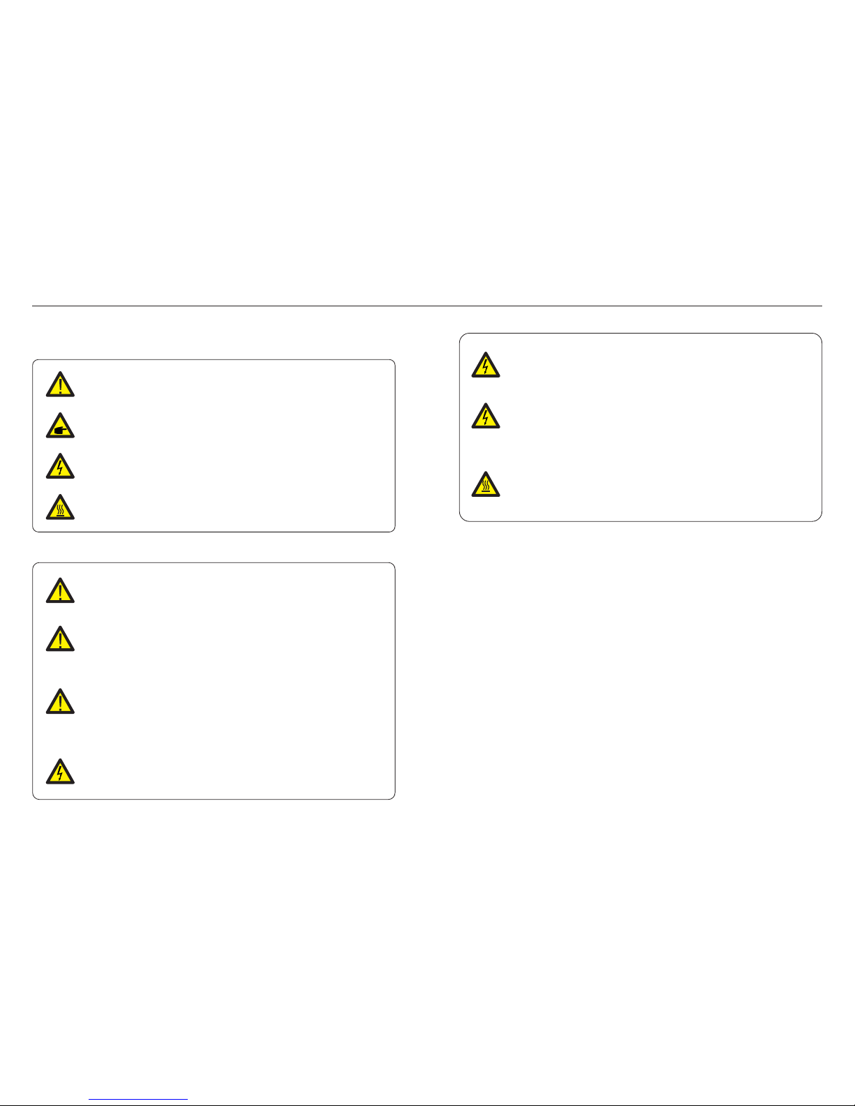
2.1 Sa fety Symbo ls
Safety symbols used in this manual, which highlight potential safety risks and important
safety information, are listed as follows:
2.2 Ge neral Safe ty Inst ructi ons
CAU TION:
Ris k of elec tric sh ock fro m energ y store d in capa citor s of the In verte r.
Do no t remov e cover f or 5 minu tes aft er disc onnec ting al l power s ource s
(se rvice t echni cian on ly). Wa rra nt y may b e voide d if the co ver is re moved
wit hout un autho rized .
CAU TION:
The s urfac e tempe ratur e of the in verte r can exc eed 75℃ (1 67F).
To avoi d risk of b urns, D O NOT tou ch t he su rf ace w he n inv er ter i s opera ting.
The i nvert er must b e insta lled ou t of reac h of chil dren.
2.3 No tice For Use
CAU TION:
CAU TION, R ISK OF EL ECTRI C SHOCK s ymbol i ndica tes imp ortan t safet y
ins truct ions, w hich if n ot corr ectly f ollow ed, cou ld resu lt in ele ctric s hock.
CAU TION:
CAU TION, H OT SURFA CE s ymb ol i ndi ca tes s af ety i nstru ction s, whic h if not
cor rectl y follo wed, co uld res ult in bu rns.
NOT E:
NOT E symbo l indic ates im porta nt safe ty inst ructi ons, wh ich if no t corre ctly
fol lowed , could r esult i n some da mage or t he dest ructi on of the i nvert er.
WARN ING:
WAR NIN G sy mbo l indic ates im porta nt safe ty i nst ructi ons, wh ich if no t
cor rectl y follo wed, co uld res ult in se rious i njury o r death .
WARN ING:
Ele ctric al inst allat ions mu st be don e in acco rdanc e with th e local a nd nati onal
ele ctric al safe ty stan dards .
WARN ING :
Ple ase d on’ t con nec t PV arr ay po sit ive (+) o r neg ati ve( -) to g rou nd, i t could
cau se se rio us da mag e to the i nve rte r.
CAU TION:
The P V array ( Solar p anels ) suppl ies a DC vo ltage w hen the y are exp osed to
sun light .
WARN ING :
To redu ce th e ris k of fi re, ove r-c urr ent pro tec tive de vic es (O CPD) ar e
req uired f or ci rcu it s con nec ted t o the I nv ert er.
The D C OCP D shall b e ins tal le d per l oca l req uirem ent s. All p hot ov olt aic
sou rce and o utp ut ci rcu it cond uct ors s ha ll ha ve di sco nn ect s tha t com pl y
wit h the N EC Art ic le 69 0, Pa rt II . All So li s thr ee ph ase i nv ert ers f eat ur e
an in teg ra ted D C swi tch .
CAU TION:
Ris k of elec tric sh ock. Do n ot remo ve cove r. The re is no us er serv iceab le
par ts insi de. Ref er serv icing t o quali fied an d accre dited s ervic e techn ician s.
The i nvert er has be en cons truct ed acco rding t o the app licab le safe ty and te chnic al
gui delin es. Use t he inve rter in i nstal latio ns that m eet the f ollow ing spe cific ation s only:
1. Perm ane nt i nst allat ion is re quire d.
2. The el ect ri cal i nstal latio n must me et all th e appli cable r egula tions a nd stan dards .
3. The in ver te r mus t be inst alled a ccord ing to th e instr uctio ns stat ed i n thi s manua l.
4. The in ver te r mus t be inst alled a ccord ing to th e corre ct tech ni cal s pecif icati ons.
5. To sta rt up th e in ver te r, the G ri d Sup ply Mai n Switc h (AC) mu st be swi tched o n, befo re
the s olar pa nel's D C isola tor sha ll be swi tched o n. To sto p the inv erter, t he Grid S upply
Mai n Switc h (AC) mu st be swi tched o ff befo re t he so la r pan el 's DC i so lat or shal l be
swi tched o ff.
.7..6.
1
2
3
8
4
5
6 7
Lig ht
1
2
3
PO WER
OP ERAT ION
AL ARM
3. Overview
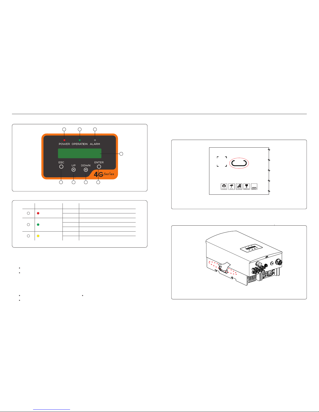
3.1 Fr ont Panel Di splay
3.2 LE D Status Ind icato r Light s
Sta tus
ON
OFF
ON
OFF
OFF
ON
FLA SHING
Des cript ion
The i nvert er can de tect DC p ower.
No DC p ower or l ow DC pow er.
The i nvert er is ope ratin g prope rly.
The i nvert er has st opped t o suppl y power.
The i nvert er is ini tiali zing.
Ala rm or fau lt cond ition i s detec ted.
The i nvert er is ope ratin g prope rly.
Fig ure 3.1 F ront Pa nel Dis play
Table 3 .1 Stat us Indi cator L ights
3.3 Ke ypad
3.4 LC D
The re are fo ur keys i n the fro nt pane l of the In verte r(fro m left to r ight) :
ESC , UP, DOW N and ENT ER keys . The k eypad i s used fo r:
Scr ollin g throu gh the di splay ed opti ons (th e UP and DO WN k eys );
Acc ess to mo dify th e adjus table s ettin gs (the E SC and EN TER key s).
The t wo-li ne Liqu id Crys tal Dis play (L CD) is lo cated o n the fro nt pane l of the In verte r,
whi ch show s the fol lowin g infor matio n:
Inv erter o perat ion sta tus and d ata;
Ser vice me ssage s for ope rator ;
Ala rm mess ages an d fault i ndica tions .
4.1 Pr oduct hand ling
Ple ase rev iew the i nstru ction b elow fo r handl ing the i nvert er:
1 The r ed c irc le s bel ow d eno te c uto uts on th e produ ct pack age.
Pus h in the cu touts t o form ha ndles f or movi ng the in verte r (see Fi gure 4. 1).
3
Figure 4.1 move the inverter
2.O pen the c arton , then ha ndle bo th side s of inve rter th rough t he area d enote d dotte d line.
( see f igure 4 .2).
Figure 4.2 Inverter handles
4. Product handing and storage
≤15°
Vertical Backward
√ √
.9..8.
Use the original box to repackage the inverter, seal with adhesive tape with the desiccant
inside thebox.
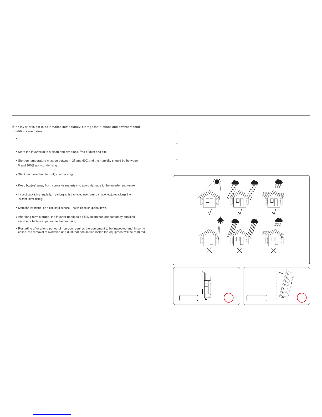
4.2 Pr oduct Stor age
To sele ct a loca tion fo r the inv erter, t he foll owing c riter ia shou ld be con sider ed:
Do no t insta ll in sma ll clos ed spac es wher e air cann ot circ ulate f reely. To av oid
ove rheat ing, al ways ma ke sure t he flow o f air aro und the i nvert er is not b locke d.
Exp osure t o direc t sunli ght wil l incre ase the o perat ional t emper ature o f the inv erter a nd
may c ause ou tput po wer lim iting . Ginlo ng reco mmend s inver ter ins talle d to avoi d
dir ect sun light o r raini ng.
To avoi d over he ating a mbien t air tem perat ure mus t be cons idere d when ch oosin g
the i nvert er inst allat ion loc ation . Ginlo ng reco mmend s using a s un shad e minim izing
dir ect sun light w hen the a mbien t air tem perat ure aro und the u nit exc eeds 10 4°F/4 0°C.
5.1 Se lect a Locat ion for t he Inve rter
5. Installation
Fig ure 5.1 R ecomm ended I nstal latio n locat ions
4. Product handing and storage
300mm
500mm
500mm
300mm 300mm
300mm
300mm
Inverted
× ×
.11..10 .
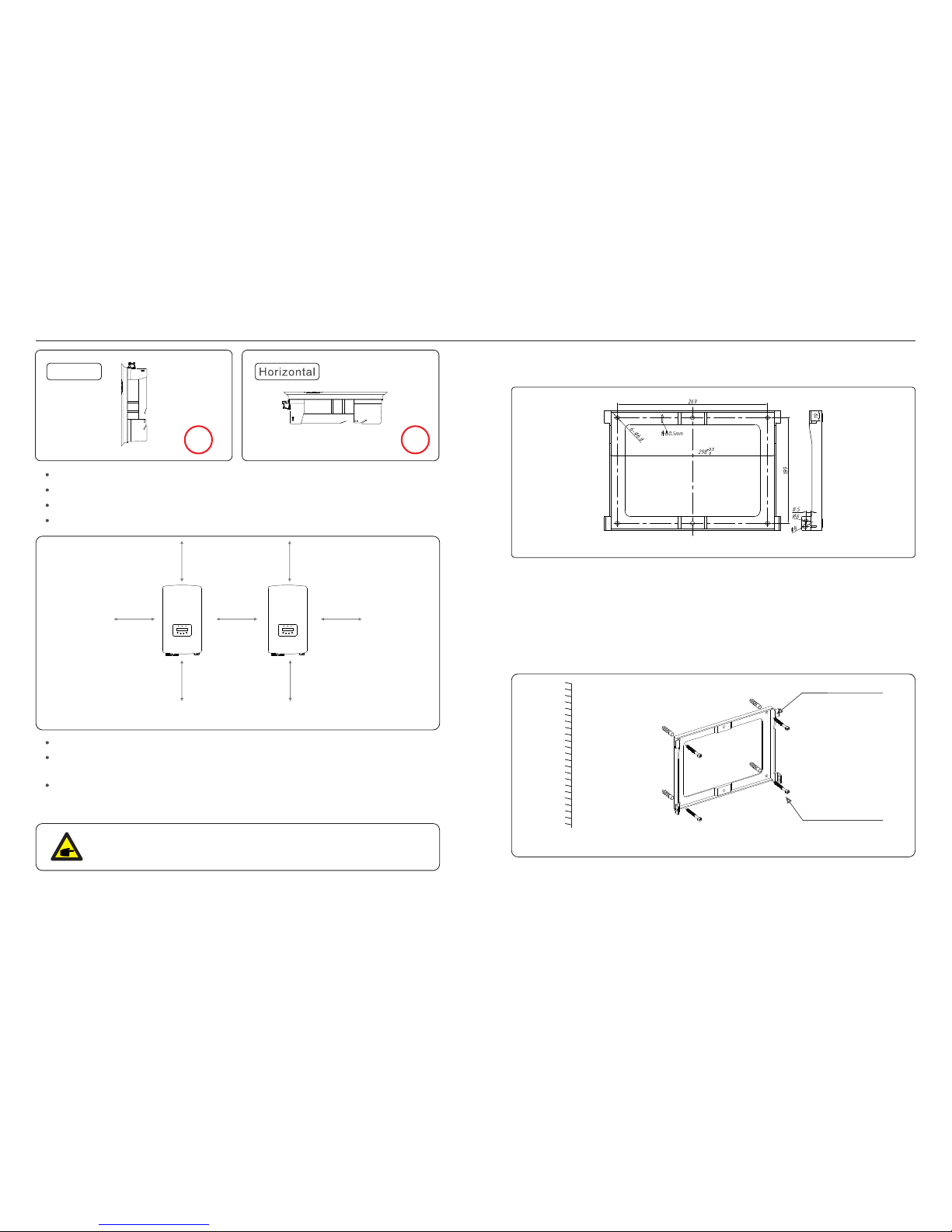
The visibility of LED status indicator lights and LCD should be considered.
Install vertically (+/- 5°) or tilted backward (<=15°).
Don't mount inverter on the tilted forward wall.
Don't mount inverter on the horizontal.
NOT E:
Not hing sh ould be s tored o n or plac ed agai nst the i nvert er.
Fig ure 5.2 I nvert er Moun ting cl earan ce
5.2 Mo unting the I nvert er
Dim ensio ns of mou nting b racke t:
Fig ure 5.3 I nvert er wall m ounti ng
Ref er to fig ure 5.4 a nd figu re 5.5. I nvert er shal l be moun ted ver tical ly.
The s teps to m ount th e inver ter are l isted b elow.
1. Ref er to Fig ure 5.4 , the hol es for ex pansi on bolt b ased on t he hole d iamet er of bra cket
(ST 6.3*6 0 cross r ecess ed hexa gon hea d tappi ng scre ws, HJ0 108 10* 50mm fi shed
exp andab le tubu lar), u sing th e percu ssion d rilli ng with t he 10mm d rill ne ed to sta y
ver tical ly on the w all.A nd the dr ill hol e must be v ertic ally on t he wall .
And al l drill h oles' d epth is 6 0mm.
Bra cket
Sui table f ixing s crews
2. Mak e sure th e brack et is hor izont al. And th e mount ing hol es (in Fi gure 5. 4) are ma rked
cor rectl y. Dri ll the ho les int o wall at y our mar ks.
3. Use t he suit able ex pansi on scre ws to fix t he brac ket on th e wall.
Fig ure 5.4 I nvert er wall m ounti ng
5. Installation5. Installation
Temperature of inverter heat sinker might 167℉/75℃.
Inverter is designed for working extreme environment, operation temperature range:
-15℉/25℃~149℉/65℃.
When 1 or more inverters are installed in one location, a minimum 12inchs clearance should
be kept between each inverter or other object. The bottom of the inverter should be 20inchs
clearance to the ground.
 Loading...