

SOLIS mini-700-4G,mini-1000-4G,mini-1500-4G,mini-2000-4G,mini-2500-4G,mini-3000-4G,mini-3600-4G Installation And Operation Manual

2016, Ningbo Ginlong Technologies Co., Ltd.
C
PV Grid Tie Inverter
Inst al la tion and Oper at ion Manual
Solis 4G Mini Single Phase Inverter
Ver 1. 2
Sol is-mi ni-70 0-4G, S olis- mini- 1000- 4G, Sol is-mi ni-15 00-4G , Solis -mini -2000 -4G,
Sol is-mi ni-25 00-4G , Solis -mini -3000 -4G, So lis-m ini-3 600-4 G
Ningb o Gi nlong Tec hnolo gi es Co., L td .
No. 57 Ji nt ong Roa d, B inhai I nd ust ri al Park , Xi angsh an , Ningb o,
Zheji an g, 3157 12 , P.R.C hi na.
Tel: +86 (0 )5 74 6578 1 80 6
Fax: +8 6 (0 )574 65 78 1 606
If you en cou nt er an y pr obl em o n the i nvert er, pl ea se fi nd o ut th e in ver ter S/N
and con tac t us , we wi ll t ry to r espon d to yo ur q ues ti on ASA P.

1. Introduction
2. Safety Instructions
2.1 Safety Symbols
2.2 General Safety Instructions
2.3 Notice For Use
3. Overview
3.1 Front Panel Display
3.2 LED Status Indicator Lights
3.3 Keypad
3.4 LCD
4. Installation
4.1 Select Location for the Inverter
4.2 Mounting the Inverter
4.3 Electrical Connections
Contents
.1.
3
5
5
5
6
7
7
7
8
8
9
9
11
13
………………………
………………………………………
………………………………………………
………………………………
………………………
……………………………………………
…………………………………………………
………………………………………………
…………………
…………………………………
……………………………
6. Operation
24
………………………………………………
5. Start & Stop
5.1 Start the Inverter
5.2 Stop the Inverter
23
23
23
………………………………………
………………………………
…………………………………
………………………………………………
……………………………………
………………………………………
1.1 Product Description
3
…………………………………
1.2 Packaging
4
…………………………………………
4.3.1 Connect PV side of inverter
13
………………
4.3.2 Connect grid side of inverter
16
………………
4.3.3 External ground connection
18
………………
4.3.4 Max. overcurrent protection device (OCPD)
19
…
4.3.5 Inverter monitoring connection
19
……………
4.3.8 DRED port conne ct io ns (O nl y for AUS.)
4.3.7 CT co nn ec ti on s
21
……………………………
21
…
4.3.6 El ec tr ic al c on nection diagram
20
…………

1. Introduction
1.1 Pr oduct Des cription
Figure 1.1 Front side view
.3.
Sol is 4G min i serie s singl e phase i nvert ers int egrat e DRM and b ackfl ow powe r contr ol
fun ction , thatc ould su itabl e for sma rt grid r equir ement .
Min i Singl e phase 4 G serie s inver ter con tain 7 mo dels wh ich are l isted b elow:
Figure 1.2 Bottom side view
DC Switch(optional)
DC input
AC input
RS 485
LCD display
4 buttons
LED lights
6.3 Settings
6.3.1 Set Time
6.3.2 Set Address
6.4 Advanced Info.
6.4.1 Alarm Message
Contents
.2.
26
26
26
27
27
………………………………………………
………………………………………
……………………………………
………………………………………
………………………………
6.4.3 Version
6.4.4 Daily Energy
6.4.5 Monthly Energy and Yearly Energy
6.5 Advanced Settings
6.5.1 Select Standard
6.5.2 Grid ON/OFF
7. Maintenance
8. Troubleshooting
9. Specifications
28
28
28
29
29
31
37
37
40
…………………………………………
……………………………………
…………
…………………………………
………………………………
…………………………………
………………………………………………
…………………………………………
……………………………………………
6.4.2 Running Message
28
……………………………
32
……………………………
6.5.3 Clear Energy
6.5.4 New Password
31
31
………………………………
…………………………………
6.2.1 Lock screen 26
……………………………………
9.1 Technical data 40
…………………………………………
6.4.6 Daily record
6.4.7 Communication Data
29
29
……………………………………
…………………………
6.5.5 Power control
6.5.6 Calibrate Energy
31
32
………………………………
…………………………………
6.2 Information
24
………………………………………
CT input
DRM port
6.1 Main Menu
24
…………………………………………
6.5.7 AU S S T D . Se tt in gs
34
………………………………6.5.8 EMP Settings
Sol is-mi ni-70 0-4G, S olis- mini- 1000- 4G, Sol is-mi ni-15 00-4G , Solis -mini -2000 -4G,
Sol is-mi ni-25 00-4G , Solis -mini -3000 -4G, So lis-m ini-3 600-4 G

2.Safety Instructions
2.2 Ge neral Saf ety Instruc tions
WARNIN G:
Ele ctric al inst allat ions mu st be don e in acco rdanc e with th e local a nd nati onal
ele ctric al safe ty stan dards .
.5.
CAUTI ON:
CAU TION, R ISK OF EL ECTRI C SHOCK s ymbol i ndica tes imp ortan t safet y
ins truct ions, w hich if n ot corr ectly f ollow ed, cou ld resu lt in ele ctric s hock.
CAUTI ON:
CAU TION, H OT SURFA CE sy mbol in dicat es safe ty inst ructi ons, wh ich if no t
cor rectl y follo wed, co uld res ult in bu rns.
NOTE:
NOT E symbo l indic ates im porta nt safe ty inst ructi ons, wh ich if no t corre ctly
fol lowed , could r esult i n some da mage or t he dest ructi on of the i nvert er.
2.1 Sa fety Symb ols
Saf ety sym bols us ed in thi s manua l, whic h highl ight po tenti al safe ty risk s and imp ortan t
saf ety inf ormat ion, ar e liste d as foll ows:
WARNIN G:
WAR NIN G sym bol ind icate s impor tant sa fety in struc tions , which i f not
cor rectl y follo wed, co uld res ult in se rious i njury o r death .
Imp roper u se may re sult in p otent ial ele ctric s hock ha zards o r burns . Th is ma nua l
con tains i mport ant ins truct ions th at shou ld be fol lowed d uring i nstal latio n and
mai ntena nce. Pl ease re ad thes e instr uctio ns care fully b efore u se and ke ep them f or
fut ure ref erenc e.
WARN ING :
Ple ase d on’t c onn ect P V arra y pos iti ve(+) or ne gat ive (-) to g rou nd, it c oul d
cau se se riou s dam age t o the in ver ter.
1. Introduction
.4.
1.2 Pa ckaging
Par t #
1
Des cript ion
PV gr id tie in verte r
2
Wal l/p ole b racke t
3
Loc king sc rews
4
1
7
32
4
5
Num ber
1
1
2
1pa irs
When you receive the inverter, ensure that all the parts listed below are included:
Table 1.1 Parts list
Gro undin g screw
1
5
AC c onnec tor
6
1
6
Man ual
7
1
DC c onnec tor
CT w ith c able (o ption al)
8
1
WARN ING :
Onl y dev ices i n com pli ance w ith S ELV (EN 6 9050) may b e connect ed to t he
RS4 85 and U SB in ter face s.
WARNIN G:
Do no t touch a ny inne r live pa rts unt il 5 minu tes aft er disc onnec tion fr om
the u tilit y grid an d the PV in put.
2016, Ningbo Gin long Tech nolog ies Co. , Ltd.
C
PV Grid Tie Inv erter
Installatio n and Ope ratio n Manua l
Solis 4G Mini Single Phase Inverter
Ver 1.2
Solis-mini-700-4 G, Soli s-min i-100 0-4G, S olis- mini- 1500- 4G, Sol is-mi ni-20 00-4G ,
Solis-mini-2500- 4G, Sol is-mi ni-30 00-4G , Solis -mini -3600 -4G
3. Overview
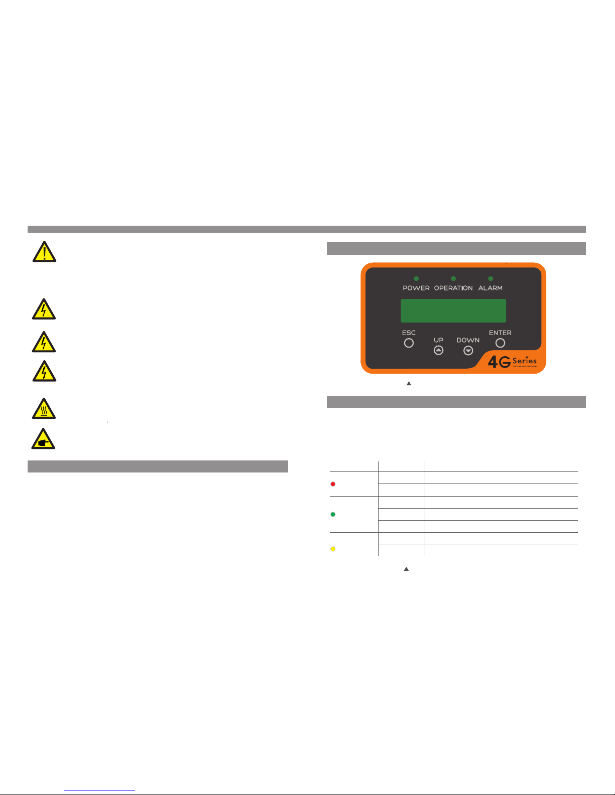
3.1 Fr ont Panel D isplay
Fig ure 3.1 F ront Pa nel Dis play
3.2 LE D Status In dicator Lig hts
The re are th ree LED s tatus i ndica tor lig hts in th e front p anel of t he inve rter. Le ft LED:
POW ER LED (r ed) ind icate s the pow er stat us of the i nvert er. Midd le LED: O PERATI ON
LED ( green ) indic ates th e opera tion st atus. R ight LE D: ALARM L ED (yel low) in dicat es
the a larm st atus. P lease s ee Tab le 3. 1 for d etail s
Des cript ion
The i nvert er can de tect DC p ower
No DC p ower or l ow DC pow er
The i nvert er is ope ratin g prope rly.
The i nvert er has st opped t o suppl y power.
The i nvert er is ini tiali zing.
Ala rm or fau lt cond ition i s detec ted.
The i nvert er is ope ratin g prope rly.
Sta tus
ON
OFF
ON
OFF
OFF
ON
FLA SHING
Lig ht
POW ER
OPE RATION
ALA RM
Table 3 .1 Stat us Indi cator L ights
.7.
2.Safety Instructions
2.3 No tice For Us e
The i nvert er has be en cons truct ed acco rding t o the app licab le safe ty and te chnic al
gui delin es. Use t he inve rter in i nstal latio ns that m eet the f ollow ing spe cific ation s ONLY:
1. Perm ane nt inst allat ion is re quire d.
2. The el ect rical i nstal latio n must me et all th e appli cable r egula tions a nd stan dards .
3. The in ver ter mus t be inst alled a ccord ing to th e instr uctio ns stat ed in thi s manua l.
4. The in ver ter mus t be inst alled a ccord ing to th e corre ct tech nical s pecif icati ons.
5. To st art up th e inver ter, the G rid Sup ply Mai n Switc h (AC) mu st be swi tched o n, befo re
the s olar pa nel's D C isola tor sha ll be swi tched o n. To st op th e inv erter, t he Grid S upply
Mai n Switc h (AC) mu st be swi tched o ff befo re th e solar p anel' s DC isol ator sh all be
swi tched o ff.
.6.
CAUTI ON:
The P V array ( Solar p anels ) suppl ies a DC vo ltage w hen the y are exp osed to
sun light .
CAUTI ON:
Ris k of elec tric sh ock fro m energ y store d in capa citor s of the In verte r. Do not
remove cover for 5 minute s after disconnect ing all power sources(s ervice techni cian
onl y). War ran ty ma y be void ed if the c over is r emove d witho ut unau thori zed .
CAUTI ON:
The s urfac e tempe ratur e of the in verte r can rea ch up to 75℃ ( 167 F).
To avoid risk o f burns , do not touc h the surf ace of th e inverter whil e it’s ope rati ng.
Inv erter m ust be in stall ed out of t he reac h of chil dren.
WARN ING:
To redu ce th e ris k of fi re, o ver -cu rre nt pr ote cti ve de vic es (O CPD ) are
req uir ed fo r cir cui ts co nnect ed to th e Inver ter.
The D C OCP D sha ll be i nst all ed pe r loc al re qui rem ents. All p hot ovo ltaic s our ce
and o utp ut ci rcu it co ndu ctors sh all hav e dis con nec ts th at co mpl y wit h the N EC
Arti cle 6 90, P art I I. All S oli s sin gle p has e inv ert ers f eat ure a n int egr ate d
DC sw itc h.
CAUTI ON:
Ris k of elec tric sh ock. Do n ot remo ve cove r. Th ere i s no us er serv iceab le
par ts insi de. Ref er serv icing t o quali fied an d accre dited s ervic e techn ician s.
PV m odule u sed wit h inver ter mus t have an IE C 61 730 C la ss A rati ng.

4. Installation
4.1 Se lect a Loca tion for the In verter
.9.
3.3 Ke ypad
3.4 LC D
The re are fo ur keys i n the fro nt pane l of the In verte r(fro m left to r ight) :
ESC , UP, DO WN an d ENT ER keys . Th e key pad is us ed fo r:
Scr ollin g throu gh the di splay ed opti ons (th e UP and DO WN ke ys);
Acc ess to mo dify th e adjus table s ettin gs (the E SC and EN TER key s).
3. Overview
The t wo-li ne Liqu id Crys tal Dis play (L CD) is lo cated o n the fro nt pane l of the In verte r,
whi ch show s the fol lowin g infor matio n:
Inv erter o perat ion sta tus and d ata;
Ser vice me ssage s for ope rator ;
Ala rm mess ages an d fault i ndica tions .
.8.
Fig ure 4.1 R ecomm ended I nstal latio n locat ions
To sele ct a loca tion fo r the inv erter, t he foll owing c riter ia shou ld be con sider ed:
To avoi d over he ating a mbien t air tem perat ure MUS T be c ons idere d whe n ch oos ing t he
inv erter i nstal latio n locat ion. Gi nlong r ecomm ends us ing a sun s hade mi nimiz ing dir ect
sun light w hen the a mbien t air tem perat ure aro und the u nit exc eeds 10 4°F/4 0°C.
Do no t insta ll in sma ll clos ed spac es wher e air can n ot circ ulate f reely. To av oid
ove rheat ing, al ways ma ke sure t he flow o f air aro und the i nvert er is not b locke d.
Exp osure t o direc t sunli ght wil l incre ase the o perat ional t emper ature o f the inv erter a nd
may c ause ou tput po wer lim iting . Ginlo ng reco mmend s inver ter ins talle d to avoi d
dir ect sun light o r raini ng.
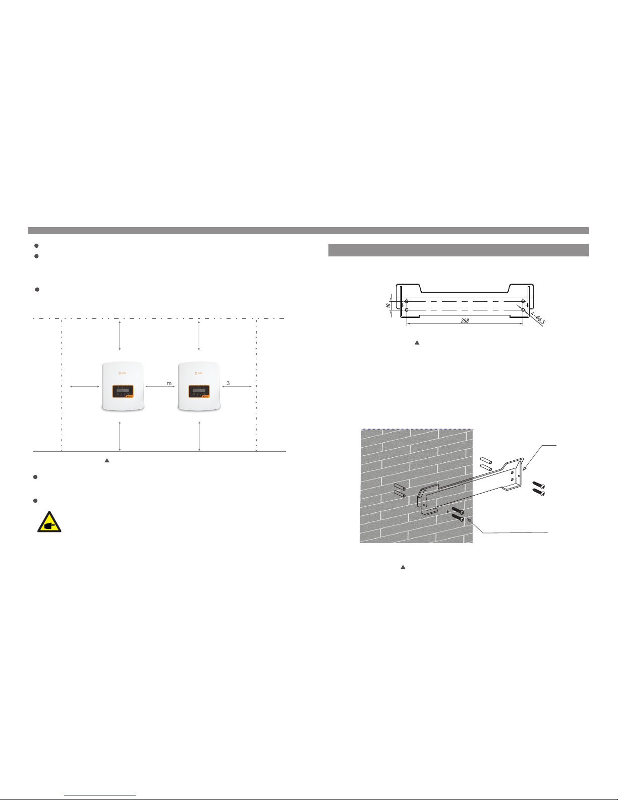
Whe n 1 or mo re in ver ter s are i nst all ed in o ne lo cat ion , a min imu m 300 mm cl ear anc e
sho uld b e kep t bet wee n eac h inv ert er or o the r obj ect . The b ott om of t he in ver ter s hou ld
be 50 0mm c lea ran ce to t he gr oun d.
Vis ibi lity of t he LED st atus in dicat or ligh ts and th e LCD loc ated at t he fron t panel o f
the i nvert er shou ld be con sider ed.
Adeq uate ve ntil atio n must be pro vide d if the inv erte r is to be inst alled i n a confin ed spac e.
NOTE:
Not hing sh ould be s tored o n or plac ed agai nst the i nvert er.
300m m
300m m
300m m
300m m 300m m
300m m
300m m
Fig ure 4.2 I nvert er Moun ting cl earan ce
Ins ta llonaw allorst ron gstruc tur ecapab leofb ea rin gthewei ght .
Ins tal l vert ica lly wi th a max imu m incl ine o f +/- 5°. If the m ount ed in vert er is t ilte d to an
ang le gre ate r than t he maximu m not ed, he at dis sip ati on can b e inhi bit ed, an d may resul t
in le ss tha n expe cte d output po wer.
4. Installation4. Installation
Dim ensio ns of wal l brack et:
Ple ase see F igure 4 .4 and Fi gure 4. 5 for ins truct ion on mo untin g the inv erter.
Fig ure 4.3 I nvert er wall m ounti ng
.10 . .11.
4.2 Mo unting th e Inverter
The i nvert er shal l be moun ted ver tical ly. The st eps t o mou nt the in verte r are lis ted bel ow:
Sui table f ixing s crews
Bra cket
1. Acc ordin g to the fi gure 4. 2, sele ct the mo untin g heigh t of the br acket a nd mark t he
mou nting h oles. F or bric k walls , the pos ition o f the hol es shou ld be sui table f or the
exp ansio n bolts .
Fig ure 4.4 I nvert er wall m ounti ng
.13 .
4. Installation4. Installation
.12 .
WARN ING:
The i nvert er must b e mount ed vert icall y.
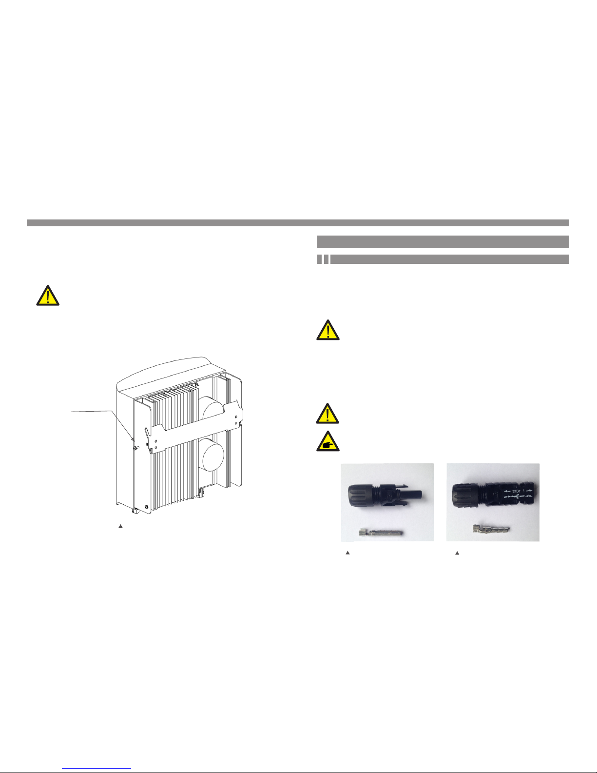
4. Lift u p the i nvert er (be ca reful t o avoid b ody str ain), a nd alig n the bac k brack et on the
inv erter w ith the c onvex s ectio n of the mo untin g brack et. Han g the inv erter o n the
mou nting b racke t and mak e sure th e inver ter is se cure (s ee Figu re 4.6)
4.3 El ectrica l Connectio ns
4.3.1 Conne ct P V si de o f in verter
The e lectr ical co nnect ion of th e inver ter mus t follo w the ste ps list ed belo w:
1. Swit ch th e Grid Su pply Ma in Swit ch (AC) O FF.
2. Swit ch th e DC Isol ator OF F.
3. As sem ble PV in put c on nec tor t o th e Inv ert er.
Bef ore c onne cti ng in ver ter, pl eas e make sure t he PV ar ray o pen c ircu it vo lta ge is
wit hin t he lim it of t he inv ert er
2.Make sure the bra cket is ho rizon tal and the m ounti ng holes (i n Figure 4.4 )
are marke d corre ctly. Dr ill the ho les into th e wall or pill ar at your ma rks.
3. Use th e sui table s crews t o fix the b racke t to the wa ll.
Fig ure 4.5 W all M oun t Brack et
5. Use M 4*9 s crews i n acces sory t o lock th e inve rter t o the m ount b racke t.
Loc king sc rews
Bef ore c onne cti on, p lea se mak e sur e the po lar ity o f the ou tpu t vol tage o f PV ar ray
mat che s the“DC +”and “D C-”sy mbols.
Max imum 600Vo c for
Sol is- min i-70 0-4 G, So lis -mini-1 000 -4G , Sol is-m ini -15 00- 4G,
Sol is- min i-20 00- 4G, S oli s-mini- 250 0-4 G, So lis- min i-3 000 -4G ,
Sol is- min i-36 00- 4G
Ple ase d on’t c onn ect P V arra y pos iti ve or ne gat ive pole to t he gr ound , it co uld
cau se se riou s dam age s to the i nve rte r
Fig ure 4.6 D C+ Conn ector Fig ure 4.7 D C- Conn ector
 Loading...