

Page 1

Page 2

Page 3

S
o
li
s
20
Page 4

SOLIS 20 OPERATOR MANUAL
Page 5
EIGENAAR EN TRACTOR DETAILS
EIGENAARS
NAAM &
ADR
ESS
TEL.NO
.
Model
:
Afleverdatum
:
Chassis No
. :
Factuur No. /
Datum
:
Motor No. :
Dynamo
Gemaakt
/ Sr. No. :
Batterij G
emaakt
/ Sr. No. :
Start motor
Gemaakt
/ Sr. No. :
FIP Sr. No. :
Hydraulische Pomp Gemaakt
/ Sr. No. :
Banden
Gemaakt
Maat
Sr. No.
Voor
(Links)
Voor
(Rechts)
Achter (Links)
Achter (Rechts)
Ik ga akkoord met alle voorwaarden ten behoeven van het onderhoud van de trekker, de garantievoorwaarden,
de systemen, de geregelde diensten & ik begrijp de werking van de trekker in het veld en met het gebruik
tijdens andere verrichtingen.
Ontving een nieuwe defectvrije tractor Chassis No. ............................................................................................
Motor No. ....................................................................... & ben volkomen tevreden met de transactie.
HANDTEKENING EIGENAAR
HANDTEKENING DEALER
TEL. NO. .................................... DATUM: .....................
* BELANGRIJKE INFORMATIE VOOR DE AFNEMER: Voor hulp met betrekking tot ons
product, neem dan contact op met onze geautoriseerde dealer of erkend servicecentrum.
Page 6

Page 7
EIGENAAR EN TRACTOR DETAILS
EIGENAARS
NAAM &
ADR
ESS
TEL.NO
.
Model
:
Afleverdatum
:
Chassis No
. :
Factuur No. /
Datum
:
Motor No. :
Dynamo
Gemaakt
/ Sr. No. :
Batterij G
emaakt
/ Sr. No. :
Start motor
Gemaakt
/ Sr. No. :
FIP Sr. No. :
Hydraulische Pomp Gemaakt
/ Sr. No. :
Banden
Gemaakt
Maat
Sr. No.
Voor
(Links)
Voor
(Rechts)
Achter (Links)
Achter (Rechts)
Ik ga akkoord met alle voorwaarden ten behoeven van het onderhoud van de trekker, de garantievoorwaarden,
de systemen, de geregelde diensten & ik begrijp de werking van de trekker in het veld en met het gebruik
tijdens andere verrichtingen.
Ontving een nieuwe defectvrije tractor Chassis No. ............................................................................................
Motor No. ....................................................................... & ben volkomen tevreden met de transactie.
HANDTEKENING EIGENAAR
HANDTEKENING DEALER
TEL. NO. .................................... DATUM: .....................
* BELANGRIJKE INFORMATIE VOOR DE AFNEMER: Voor hulp met betrekking tot ons
product, neem dan contact op met onze geautoriseerde dealer of erkend servicecentrum.
Page 8

Page 9

INLEIDING
Geachte Afnemer, wij verwelkomen u met veel plezier in uw toetreding tot de ITL familie en
bedanken u voor het vertrouwen dat in ons heeft door uw zorgvuldige keuze te laten vallen
op een van onze tractoren. Voor het gebruik van deze tractor wordt u sterk aanbevolen om
deze handleiding zorgvuldig door te lezen. Elke persoon die regelmatig of incidenteel uw
tractor gebruikt wordt geacht deze instructies door te lezen.
Werkzaamheden als dagelijks en routineonderhoud, kunnen eenvoudig worden uitgevoerd
met behulp van deze handleiding. Onze dealers staan altijd klaar om u te assisteren met het
onderhoud van uw tractor en de zuinige afstelling ervan.
Gebruik alleen originele Sonalika onderdelen van erkende dealers en leveranciers. Zo bent
u verzekert van een betrouwbare en optimaal presterende tractor.
De informatie verstrekt in deze handleiding is correct op het moment van drukken.
Verbetering en aanpassingen zijn een continue proces bij International Tractor Limited (ITL),
en zijn voorbehouden wijzigingen door te voeren zonder voorafgaande kennisgeving.
u kunt uzelf de trotse eigenaar van dit product noemen. In het geval dat u enige hulp of
ondersteuning vereist, aarzel dan niet om contact op te nemen met een van onze dealers.
Service Department (IB)
INTERNATIONAL TRACTORS LIMITED
V
ill Cha
k G
ujran
, P.O. P
iplanwala 146022
J
alandhar Road, Hoshiarpur
, P
unjab
.
P
hone: 01882-302-288
/
289
/
299
, Fax:
01882-302-555
.
E
-mail: export@sonalika.com
SOLIS 20 OPERATOR MANUAL
Page 10

UW RECHTEN
Tijdens de afname van een nieuwe “Solis 20” Tractor,
kunt U de dealer While taking delivery of new ?
SOLIS
20"Tractor, kindly ask the dealer to give following
items:
1.
Tool kit which includes
Grease Gun (Optional) 1pc
D-spanner 10x 11 1pc
D-spanner 12X 13 1pc
D-spanner 14X 17 1pc
D-spanner 18X 19 1pc
D-spanner 20X 22 1pc
D-spanner 30X 32 1pc
Ring spanner 16X 17 1pc
Battery Guarantee card 1pc
Ring Spanner 24X 27
2. Farmer Kit
Fuel Filter Catridge (703008219a ) 3
Oil Filter Assy. 3 Cyl.(803007059a) 2
Fan Belt (703006099a) 1
Linch Pin (10080109ab) 3
Fuel Tank Cap With Key (10071015ac) 1
Tyre Pressure Gauge (10026665aa) 1
Fuses For Farmer Kit (10071358aa) 1
Hose Pipe For Air Cleaner(10051220ba) 1
Cap For Radiator (10026958aa) 1
3. To avail the services
.
4.
To call dealers any time for any breakdown
.
5. Additional Accessories as Standard fitment
Safety Reflector
Plough Lamp (1pc) (Optional)
Rear View Mirror
SOLIS 20 OPERATOR MANUAL
Page 11
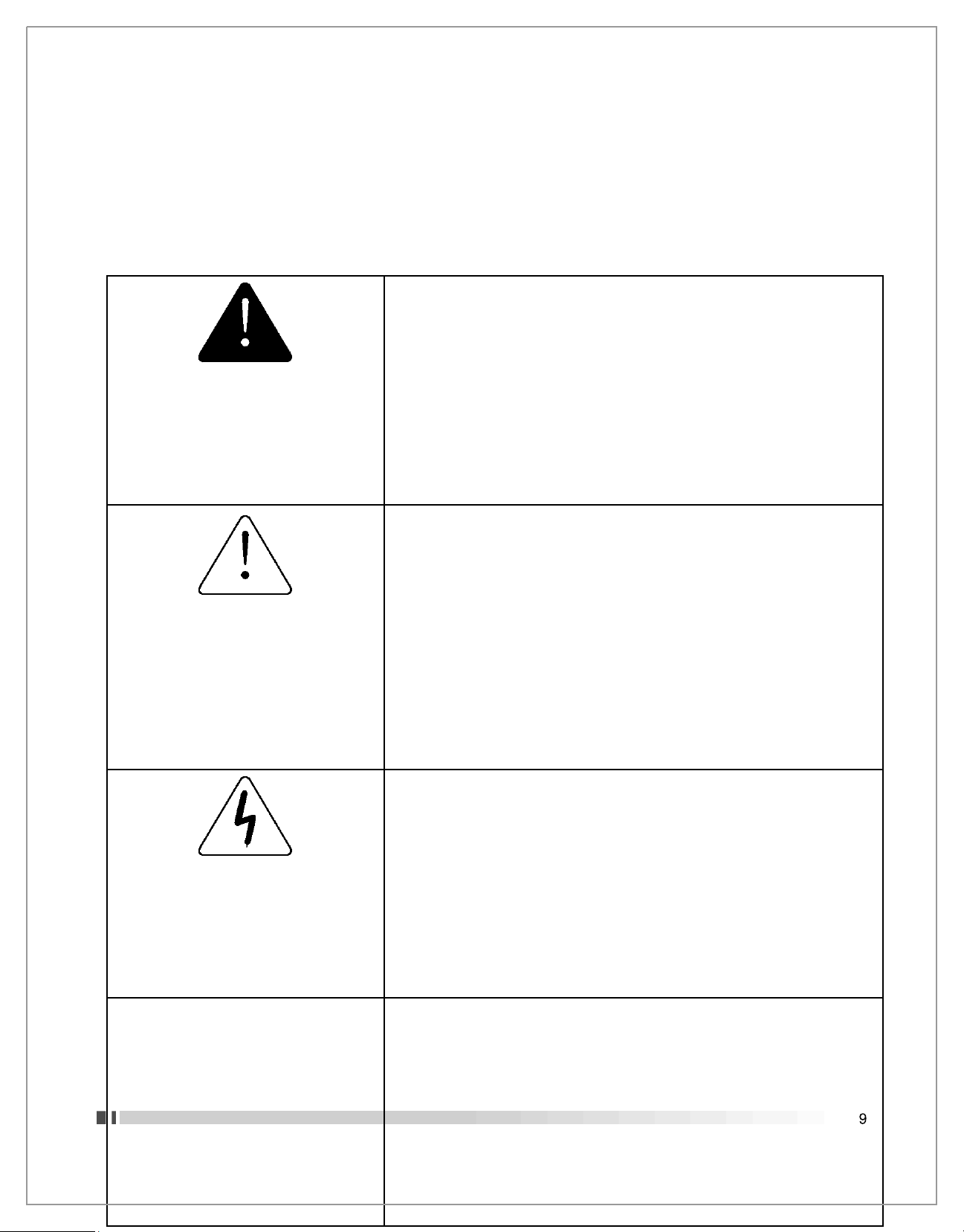
DANGER
Dit symbool en het
woord
“
DAN
GER” duiden op een
onmiddellijke gevaarlijke situatie,
die indien niet vermeden, zal leiden
tot de DOOD of ZEER ERNSTIG
LETSEL.
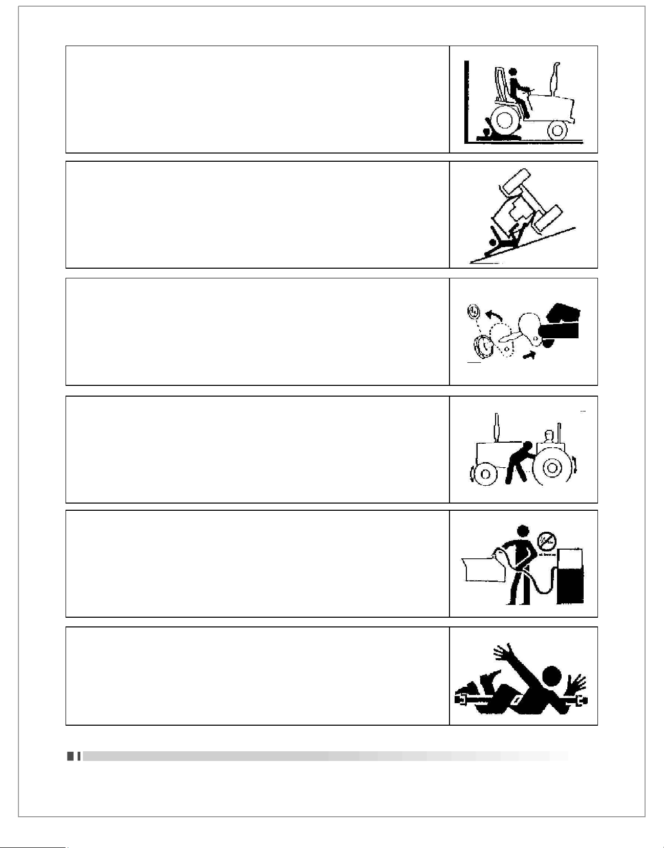
1.
Bescherm uw gezicht van een radiator onder druk als de motor
warm is. Verwijder de dop voorzichtig en alleen als de motor koud
is.
2.
Laat nooit kinderen of onbevoegden uw tractor bedienen, en houd
anderen altijd op afstand wanneer het apparaat in werking is.
WARNING
Dit symbool en het woord
“WARNING” duiden op een
potentieel gevaarlijke situatie. Als
de instructies of procedures niet
correct gevolgd worden kan dit
leiden tot de DOOD of ZEER
ERNSTIG LETSEL
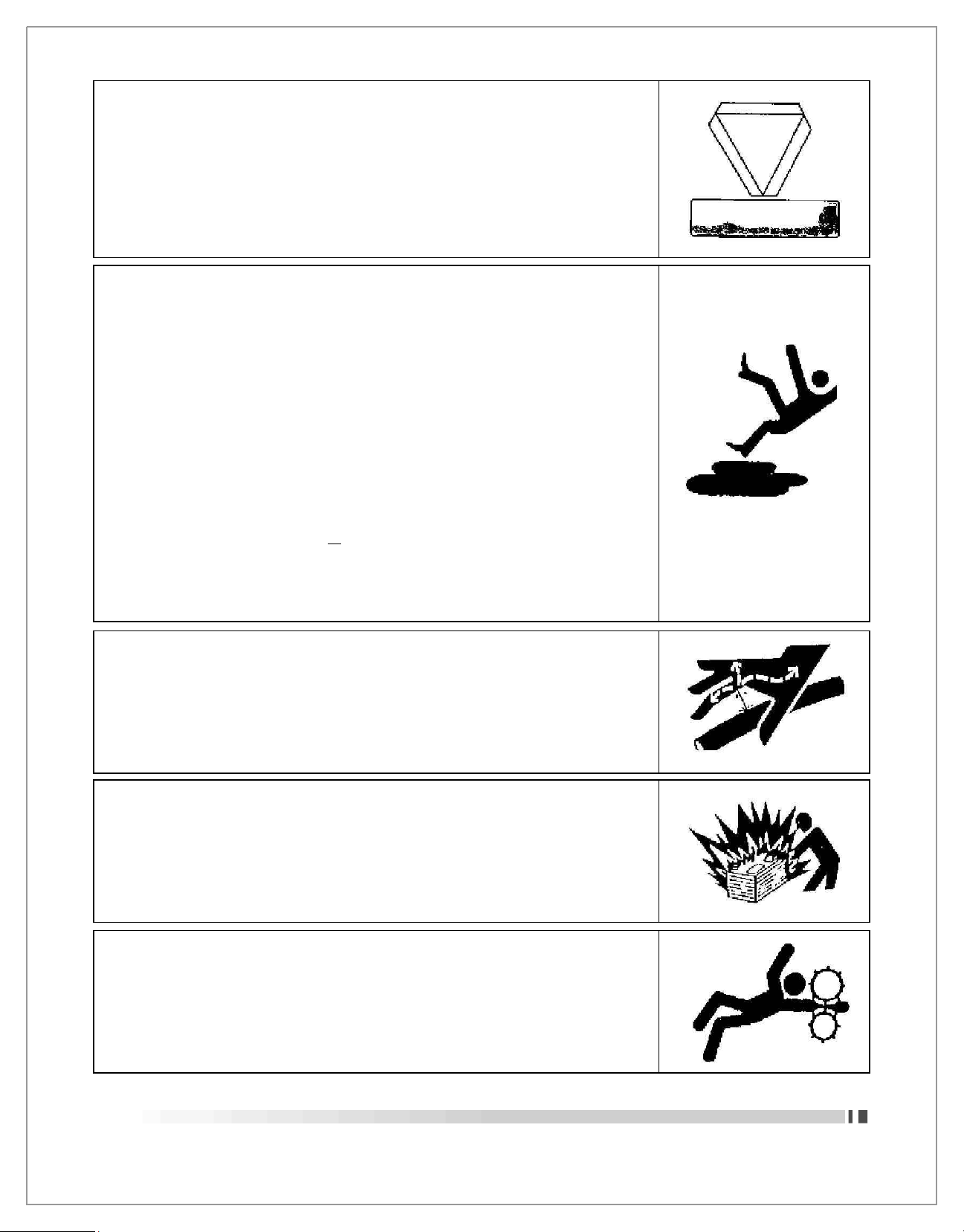
1.
Verwijder nooit de “Danger”, “Warning”, en “Caution” of instructie
labels.
2.
Een exploitant mag nooit onder invloed zijn van drank of drugs, die
zijn alertheid of coördinatie beïnvloeden.
3.
Nooit staan of toestaan dat iemand anders op of tussen de tractor
en het werktuig staat, tenzij de motor is uitgeschakeld, de
versnelling in neutraal staat, en alle uitrusting of werktuigen zijn
neergelaten op de grond.
4.
Ontkoppel nooit de koppeling en probeer niet te schakelen,
wanneer u een helling afrijdt.
5.
Overbelasting is altijd gevaarlijk. Controleer dus altijd het
laadvermogen van uw tractor en overbelast deze nooit.
6.
Koppel nooit de hydraulische aansluitingen los en pas nooit een
werktuig aan met een draaiende motor of de aftakas in werking. Dit
zou kunnen leiden tot ernstig letsel of de dood.
CAUTION
Dit symbool en het woord “Caution”
duiden op een potentieel
gevaarlijke situatie, die indien niet
vermeden, kan leiden tot LICHT
LETSEL.
1.
Laat een lopende tractor nooit ongestuurd achter, en houd ten alle
tijden een stevige grip op het stuur.
2.
Voordat u van de tractor afstapt, wordt u geacht de aftakas te
ontkoppelen, alle uitrusting en werktuigen neer te laten, de
versnelling in zijn neutraal te zetten, de handrem aan te trekken, de
motor uit te zetten en de sleutel te verwijderen.
3.
Rook niet tijdens het tanken van de tractor, en houd elke vorm van
open vuur weg.
RICHTLIJNEN OVER VEILIGHEIDSTEKENS
Erken Veiligheid Informatie:
Dit is het waarschuwingssymbool. Elk symbool op uw machine of in deze handleiding, waarschuwt u voor een
mogelijke kans om persoonlijk letsel op te lopen. Volg de aanbevolen voorzorgsmaatregelen en een veilige
bedrijfsvoering.
SOLIS 20 OPERATOR MANUAL
Page 12
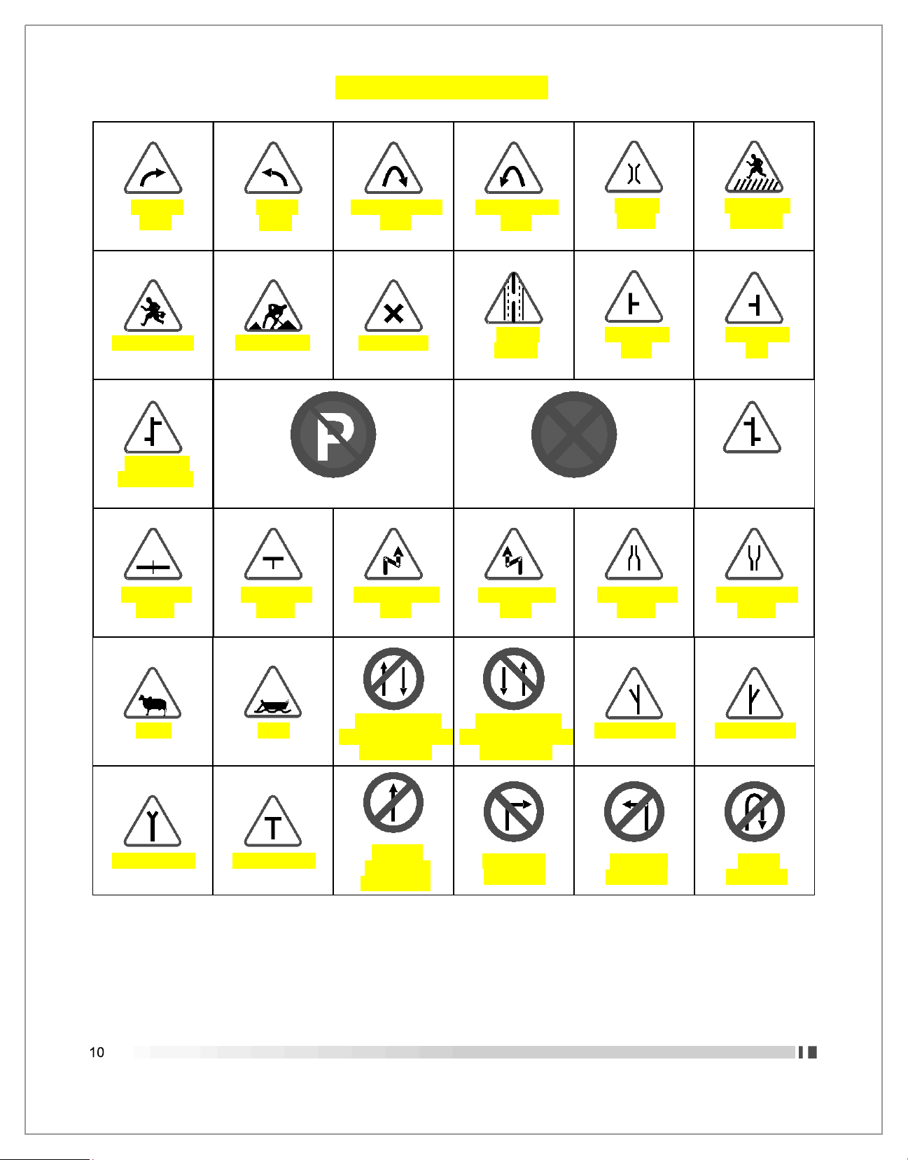
No Parking
No Stopping or Standing
Staggered
Instersection
Cattle
Ferry
One Way Signs
Vehicles Prohibited in
One Direction
One Way Signs
Vehicles Prohibited in
One Direction
Y-Intersection
Y-Intersection
Y-Intersection
T-Intersection
Straight
Prohibited
or No Entry
Right Turn
Prohibited
Left Turn
Prohibited
U-turn
Prohibited
ROAD SAFETY SIGNS
Rechtse
bocht
School Ahead
Linkse
bocht
Men at Work
Right Hand Pin
Bend
Cross Road
Left Hand Pin
Bend
Gap in
Median
Narrow
Bridge
Side Road
Right
Pedestrian
Crossing
Side Road
Left
Staggered
Instersection
Major Road
Ahead
Major Road
Ahead
Right Reverse
Bend
Left Reverse
Bend
Narrow Road
Ahead
Road Widens
Ahead
SOLIS 20 OPERATOR MANUAL
Page 13
VEILIG GEBRUIK
Voorzichtig gebruik is uw beste verzekering tegen ongelukken.
Lees deze gebruiksaanwijzing aandachtig door, voordat u de tractor bestuurd.
Alle gebruikers, ongeacht de desbetreffende ervaring, worden geacht deze gebruiksaanwijzingen te lezen
voordat men gebruik maakt van de tractor.
Het is de eigenaar zijn verplichting om elke verdere gebruiker in te lichten over het veilige gebruik van de tractor.
1
. VOOR HET GEBRUIK VAN DE TRACTOR
LEES DE VEILIGHEIDSINSTRUCTIES
Lees de veiligheidsinstructies in deze gebruiksaanwijzing aandachtig
door. Het nalaten van een van de volgende veiligheidsovereenkomsten
kan leiden tot erge verwondingen of de dood. Houd alle
veiligheidstekens in goede conditie, en vervang beschadigde of kapotte
veiligheidstekens.
Houd uw tractor in goede conditie en sta ongeautoriseerde wijzigingen
aan uw tractor niet toe, wat de werking, veiligheid, en levensduur van uw
tractor kan beïnvloeden.
Het besturen van de tractor
1
. Kijk uit waar je rijd vooral bij het einde van rijen, op wegen, bij bomen en andere bij andere obstakels.
2
. Voorkom tegenslagen, door de tractor zorgvuldig te besturen en een veilige snelheid aan te houden. Dit
geldt voornamelijk bij het werken op ruw terrein en hellingen, het oversteken van sloten, en bij het maken
van bochten
3
. Vergrendel beide rempedalen van de tractor, wanneer de tractor wordt getransporteerd over wegen.
4
. Houd de tractor in dezelfde versnelling wanneer u bergafwaarts gaat als bij het bergop rijden, en ga nooit
bergafwaarts zonder dat de tractor in zijn versnelling staat.
5
. Elk getrokken voertuig of aanhangwagen waarvan het totale gewicht hoger is dan het gewicht van de
trekkende tractor, moet worden uitgerust met eigen remmen voor een veilig gebruik.
6
. Wanneer de tractor vast raakt of wanneer deze is vast gevroren aan de grond, , back
ou
t to
prevent upse
t.
7
. Kijk met het rijden en vooral met het vervoeren van de tractor ook altijd naar de
desbetreffende toegestane hoogte op de weg.
SOLIS 20 OPERATOR MANUAL
Page 14

VEILIGHEIDS TIPS TIJDENS ONDERHOUD
1
. Check dagelijks het oliepeil, het waterpeil in de radiator en de accu op genoeg
vermogen, en verricht het onderhoud volgens de onderhoudsinstructies.
2
. Zorg altijd voor een gelijke en correcte bandenspanning voor de desbetreffende
uitgevoerde taken.
3
. Kijk altijd goed na of alle bedieningselementen en aansluitingen van de tractor en het
desbetreffende werktuig correct zijn aangesloten en naar behoren werken.
4
. Zorg ervoor dat er altijd voldoende gereedschap aanwezig is voor het verrichten van
onderhoud en kleine reparaties.
5
. Zorg er altijd voor dat onderhoud en reparaties aan de tractor worden uitgevoerd op
een vlakke en harde ondergrond.
Voer geen onderhoudswerkzaamheden uit aan de tractor totdat deze is uitgeschakeld,
de handrem is aangetrokken en de wielen zijn geblokkeerd. Wanneer de tractor in een
gesloten ruimte word onderhouden, zorg er dan voor dat de ruimte goed word
geventileerd wanneer de motor aan staat, omdat de uitlaatgassen schadelijk zijn en
uiteindelijk kunnen leiden tot de dood.
6. Werk nooit onder opgeheven werktuigen of wanneer werktuigen nog in werking zijn.
7. Zorg ervoor dat bij het verwisselen van de wielen of banden, er een geschikt standaard
onder de as van de tractor is geplaatst en de wielen zijn geblokkeerd voordat het
desbetreffende wiel of band is verwijderd.
8
. Wanneer afschermende onderdelen die dienen voor diens bescherming tijdens het
gebruik van de tractor verwijderd moeten worden voor onderhoud of reparatie, zorg er
dan altijd voor dat u deze afschermende onderdelen weer op de desbetreffende manier
installeert voordat u gebruikt maakt van de tractor.
9
. Tank nooit in de buurt van een open vlam of een oververhitte motor. En zorg er altijd
voor dat u de motor heeft uitgeschakeld voor het tanken.
10
. Het koelsysteem van de tractor werkt onder druk. Zorg bij het verwijderen van de
radiator dop dat de motor is afgekoeld, om brandwonden veroorzaakt door stoom of
heet water te voorkomen. Voeg ook nooit water toe in de radiator wanneer de motor
warm is, maar zorg ervoor dat u wacht tot deze volledig is afgekoeld.
11
. Om ontvlamming te voorkomen, zorg er dan ten alle tijden voor dat u de tractor en
motor schoon houdt en ontvlambaar materiaal en brandstoffen verwijderd.
12
SOLIS 20 OPERATOR MANUAL
Page 15
BESCHERMING VAN KINDEREN
Houdt kinderen en onbevoegden uit de buurt van de tractor indien in werking.
- Kijk voordat u achteruit rijdt naar achter of het vrij is van obstakels.
- Laat kinderen en onbevoegden nooit de tractor of een werktuig besturen.
VOORZORGSMAATREGELEN OM KANTELEN TE VOORKOMEN
Rijd niet op plekken waar de tractor mogelijk kan wegglijden of omvallen.
Blijf altijd alert voor gaten en andere obstakels.
Verlaag je snelheid bij het maken van scherpe bochten.
Het voorwaarts wegrijden uit een greppel of verzakking kan er voor
zorgen dat de tractor naar achter kantelt. Voorkom dit ten alle tijden.
PARKEER DE TRACTOR VEILIG
Nadat u gebruik heeft gemaakt van de tractor:
- Laat alle werktuigen zakken.
- Stop de motor en haal de sleutel uit het contact.
HOUD PASSAGIERS VAN DE TRACTOR
Sta geen mede-inzittende toe op de tractor.
Mede-inzittende kunnen zwaar gewond raken door beknelling, bewegende
onderdelen, of het vallen van de tractor.
V
EILIG TANKEN EN VOORKOM BRAND
Behandel brandstof met adat u gebruik heeft gemaakt van de tractor:
- Laat alle werktuigen zakken.
- Stop de motor en haal de sleutel uit het contact.
STAY CLEAR OF ROTATING SHAFTS
Entanglement inrotatingshaftcancauseseriousinjury or death.
Keep PTOshield inplaceat all times.
Wearclose fitting clothing.Stop the engineand to surePTO drive isstopped
before makingadjustments,connections,or cleaning outPTO driven equipment.
SOLIS 20 OPERATOR MANUAL
13
Page 16
ALWA
YS USE SAFETY LIGHTS
AND DR
IVES
Use of hazard warning lights and turn signals are recommended when
towing equipment on public roads unless prohibited by state or local regulations.
Use slow moving vehicle (SMV) sign when driving on public road during both day &
nigth time, unless prohibited by law.
P
RACTIC
E SAFE MAINTE
NANC
E
Understand service procedure before doing work.
Keep the surrounding area of the Tractor clean and dry.
Do not attempt to service Tractor when it is motion.
Keep body and clothing away from rotating shafts.
Always lower equipment to the ground. Stop the engine.
Remove the key equipment to the ground. Stop the engine.
Securely support any Tractor elements that must be raised for service work.
Keep all parts in good condition and properly installed.
Replace worn or broken parts. Replace damage/missing decals.
Remove any buildup of grease or oil form the Tractor.
Disconnect battery ground cable (
)
before making adjustments on electrical
system or welding on Tractor.
A
VOID HIGH-PRESSURE FLUIDS
Escaping fluid under pressure can penetrate the skin causing serious injury. Keep
hands and body away from pinholes and nozzies, which eject fluids under high
pressure. If ANY fluid is injected into the skin. Consult your doctor immediately.
PREVENT BATTERY EXPLOSIONS
Keep sparks, lighted matches, and open flame away from the top of battery.
Battery gas can explode.
Never check battery charge by placing a metal object across the poles.
SERVICE T
RACTOR SA
FELY
Do not when a necktie, scarf or loose clothing when you work near moving parts. If
these items were to get caught, severe injury could result.
Remove rings and other jeweler to prevent electrical shorts and entanglement in
moving parts.
14
SOLIS 20 OPERATOR MANUAL
Page 17
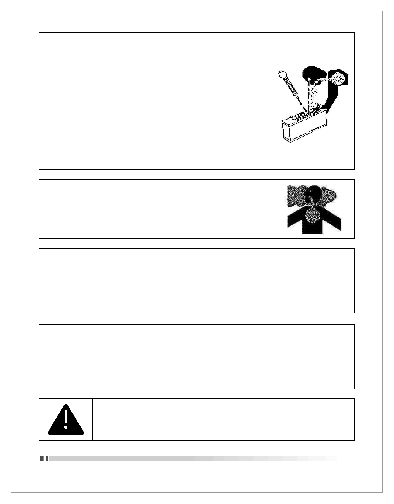
PREVENT ACID
BURN
S
Sulfuric acid in battery electrolyte is poisonous. It is strong enough to burn skin,
cause holes in clothing and cause blindness if found entry into eyes.
For adequate safety always.
1. Fill batteries in a well-ventilated area.
2. Wear eye protection and acid proof hand gloves
3. Avoid breathing direct fumes when electrolyte is added.
4. Do not add water to electrolyte as it may splash off causing server burns.
If you spill acid on your self.
1. Flush your skin with water.
2. Flush your eyes with water for 10-15 minutes.
Get medical attention immediately.
WORK IN VENTILATED AREA
Do not start the Tractor in an enclosed building unless the doors &
windows are open for proper ventilation, as tractor fumes can cause
sickness or death. If it is necessary to run an engine in an enclosed
area remove the exhaust fumes by connecting exhaust pipe extensions.
Safety Starter Switch is to be replaced after every 2000 hours/4years,
whichever is earli
T
RACTOR RUNAWA
Y
1. The tractor can start even if the transmission is engaged position causing Tractor to runaway and
serious injury to the people standing nearby the tractor. For additional safety keep the pull to slop knob
(fuel shut off control) in fully pulled out position.
Transmission in neutral position. Foot brake engaged and PTO lever in disengaged position while
attending to Safety Starter Switch or any other work on Tractor.
SAFETY STARTER SWITCH
1. Clutch operated safety switch is provided on all Tractors which allow the starting system to become
operational only when the Clutch pedal is fully pressed.
2. Do not By-pass this safety switch or work on it. Only Authorized Dealers are recommended to
work on safety starter switch.
SOLIS 20 OPERATOR MANUAL
15
Page 18

S.No.
DESCR
IPTIO
N
1
. IDENTIFICATION OF T
RACTOR
............................................................................................19
2
. INTRO
DUC
TION & DESCRIPTION........................................................................................20
3
. OPERATIONS.........................................................................................................................21
3.1
In
strumenta
l Panel................................................................................................................22
T
emperature Gauge
................................................................................................................
22
E
ngine Oil Pressure Indicator
..................................................................................................22
RPM cum Hour Recorder
........................................................................................................23
F
uel Gauge
.............................................................................................................................23
Battery
Charge Indicator
.........................................................................................................23
High Beam Indicator
...............................................................................................................23
Le
ft S
ide Indicator
...................................................................................................................23
Righ
t S
ide Indicator
.................................................................................................................24
PTO Lever Posit
ion Indication
................................................................................................24
G
ear Lever Position Indication
................................................................................................
24
3.2
El
ectrical Contr
ol :................................................................................................................25
Hazard Ligh
t Switch...............................................................................................................25
S
ide Indicator Switch
..............................................................................................................25
Combination Switch
................................................................................................................25
Start
ing Ke
y Switch................................................................................................................26
E
ngine
Stop K
nob
..................................................................................................................26
Fuse Box.................................................................................................................................26
Revolving ligh
t Switch.............................................................................................................
26
3.3
El
ectrica
l Equipments...........................................................................................................27
Battery & its
Maintenance
.......................................................................................................27
Alt
ernator
.................................................................................................................................27
V-Belt
Checking and Adjustmen
t.............................................................................................
27
Starter Motor............................................................................................................................27
G
eneral Maintenance o
f Electrical System.............................................................................28
Precaut
ions before Connecting Welding Apparatu
s...............................................................
28
3.4
Sh
eet Metal :
..........................................................................................................................28
Proc
edure to open the Top Hood
............................................................................................
28
3.5 Controls :
...............................................................................................................................29
Main Gear Shifter Lever
.........................................................................................................29
High -Low Lever
.....................................................................................................................29
2WD/4
WS Lever....................................................................................................................29
P
ower Take
Off Shifter Lever.................................................................................................30
Differential Lo
ck P
edal
...........................................................................................................30
Clutch Pedal
..........................................................................................................................30
Method to Che
ck the
Clutch Pedal Free Pla
y........................................................................
30
16
SOLIS 20 OPERATOR MANUAL
Page 19

S.No. DESCRIPTION
Foot Brake P
edal
..........................................................................................................30
Method for Che
ck Brakes.............................................................................................30
Park
ing Brake
...............................................................................................................31
Foot Acc
elerator
............................................................................................................31
Hand Throttle Lever
...................................................................................................... 31
Driver Sea
t................................................................................................................... 31
Travel A
djustmen
t.........................................................................................................31
Back A
djustmen
t...........................................................................................................31
T
ool Bo
x.....................................................................................................................
31
Seven Pin Socket..........................................................................................................32
Posit
ion Control Lever
...................................................................................................32
P
ower Take
Off............................................................................................................. 32
Registration Plate
......................................................................................................... 32
Ligh
ts............................................................................................................................32
3.6 Engine......................................................................................................................... 33
Start
ing the Engine
...................................................................................................... 33
Proc
eed a
s F
ollow
s..................................................................................................... 33
Running the Engine
......................................................................................................34
T
urning
Off the E
ngine
..................................................................................................33
3.7
Fuel S
ystem :
.............................................................................................................. 34
F
uel Saving Tip
s...........................................................................................................34
3.8 Hydra
ulic :....................................................................................................................35
Hydrauli
c System......................................................................................................... 35
Response Valve
............................................................................................................35
T
hree Point Linkage
......................................................................................................35
Quick
Release coupling
................................................................................................35
Directional Control Valve
...............................................................................................35
3.9 Wheel and T
yres :
........................................................................................................36
In f
ield operation
s......................................................................................................... 36
In
Road Operation
s...................................................................................................... 36
Recommended Load carrying Capaci
ty........................................................................36
B
allasting o
f Tractor.......................................................................................................37
F
ron
t W
heel
TOE IN.................................................................................................... 37
Checking and Adjustment o
f TOE IN............................................................................37
Rear Wheel Tra
ck Width A
djustmen
t............................................................................38
G
eneral Suggestion
s....................................................................................................38
Che
ck W
heel Nu
t Bolt...................................................................................................38
SOLIS 20 OPERATOR MANUAL
17
Page 20

S.No.
DESCR
IPTION
4
. GENERAL MAINTE
NANC
E................................................................................................39
4.1
Engine :........................................................................................................................39
E
ngine Lubrication
System...........................................................................................39
Che
ck E
ngine Oil Level
.................................................................................................39
Changing o
f E
ngine Oil
& Oil Filter...............................................................................39
Replacement o
f F
uel Filter
............................................................................................40
Air B
leeding From Fuel Injection
s System/F
uel Filter Replacemen
t............................ 40
4.2 Air Cleaner :
............................................................................................................... 40
Oil bath type
air cleaner
................................................................................................40
Cleaning of pre cleaner (Dry)
........................................................................................40
Air c
leaner bowl
&
elemen
t c
leaning (wet)
................................................................... 41
After every 50 hrs......................................................................................................... 41
4.3 Radiator :
........................................................................................................................42
Coollant Level in Radiator (Hot)
................................................................................... 42
Radiator Draining and Flushing (When Cold)
...............................................................42
Radiator Fins Cleaning
.................................................................................................42
Radiator Cap
................................................................................................................ 42
4.4 Hydra
ulic :........................................................................................................................43
T
ransmission/Hydrauli
c Oil Level..................................................................................43
Change Transmission Oil
............................................................................................. 43
Change
St
eering Gear Bo
x Oil.....................................................................................43
Checking Specification Gravi
ty of Battery Elect
rolyte
...................................................43
F
ron
t Axie Oil Level.......................................................................................................43
5
. Oth
ers
.................................................................................................................................44
Tec
hnical Parameter
s...................................................................................................44
Recommended Grade of Lubrican
ts
and grease
s........................................................47
Service Sc
hedule
......................................................................................................... 48
G
reasing
P
oin
ts............................................................................................................49
W
iring Diagram
............................................................................................................ 50
W
arran
ty........................................................................................................................51
6
. Do'S
AND DON
'TS...................................................................................................... 52
7
. T
RACTOR INSTALLA
TION CERTIFICATE................................................................ 56
8
. FREE SERVICE COUPONS........................................................................................ 59
9
. TROUBLE SHOOTING.................................................................................................67
10
. MATCHING IMPLEMENT.............................................................................................69
Specifi
cat
ions.................................................................................................. 69
Cultivator
...........................................................................................................69
Rotavator
.......................................................................................................... 70
12
. SERVICE RECORD......................................................................................................75
13
. NOTES......................................................................................................................... 76
18
SOLIS 20 OPERATOR MANUAL
Page 21
INTERNATIONAL TRACTORS LTD.
Type :
EEC number :
Identification number :
Total Permissible mass (*) :
Permissible front axle load (*) :
Permissible rear axle load (*) :
to
to
to
kg
kg
kg
(*) depending on the tyres.
Permissible towable mass:
Unbraked towable mass:
Independently-braked towable mass:
kg
Inertia-braked towable mass:
kg
Towable mass fitted with an assisted braking system:
kg
(hydraulic or pneumatic)
INTERNATIONAL TRACTORS LIMITED
HOSHIARPUR, PUNJAB (INDIA)
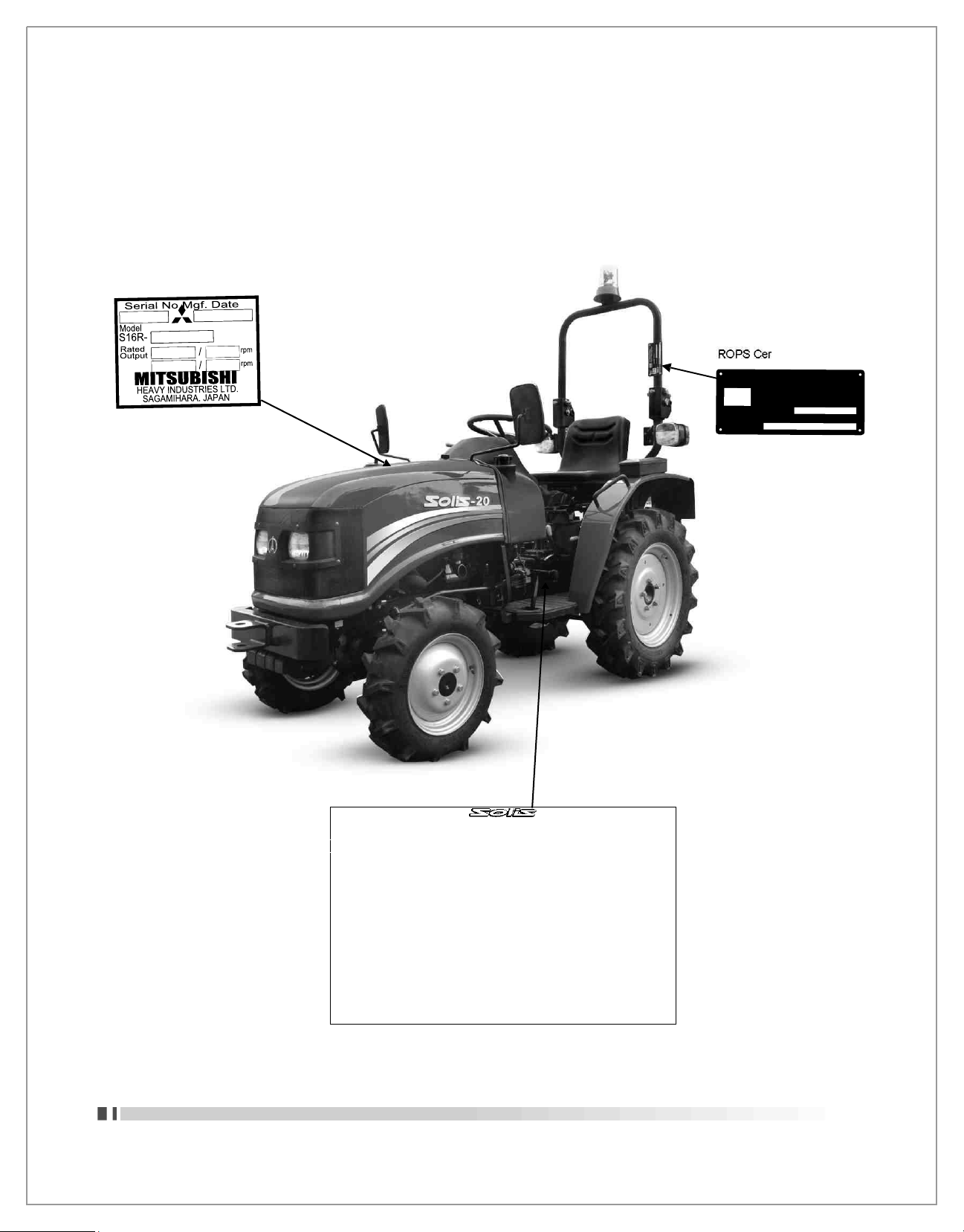
1
. IDENTIFI
CA
TION OF T
RAC
TO
R
Solis 20, Homologation
Certificate
E
11*2010/22*0209*00
Revis
ion 00 issued by the vehicle
certificat
ion agency on the approval
authority
in the United Kingdom
SV
e11
rtificate Plate
INTERNATIONAL
TRACTORS LIMITED
TRACTOR TYPE T 2
3003
Serial No.
Tractor Model
Solis 20 4WD
SOLIS 20 OPERATOR MANUAL
19
1
kg
Page 22
2. INTRODUCTION & DESCRIPTION
T
RACTOR AN INTRODUC
TION
The
word
, 'Tractor' has
been derived from
'Tract
ion' which means pulling
.
A Tractor is
required to pull or haul an equipmen
t,
implement or trolley which are coupled to the
Tractor
bod
y t
hrough suitable linkage
. ATractor can also be used as a
prime mover as it has power
outle
t s
ource which is also called Power Take o
ff or PTO shaft.
In this
book the operating, maintenance and
st
orage instruction
s for S
olis-20 Tractor has been
c
omplied
. This mat
erial has been prepared in detail to help you in the better understanding o
f
maintenance and efficient operation o
f the mac
hine
.
If you
need any information not given in this manual or require the services of a trained machani
cs,
please get in touch with the
ITL
Dealer/Distributor in your locali
ty,
Dealer/Distributors are kep
t
informed o
f the latest met
hods o
f servic
ing Tractor
s. They stock
genuine spare par
ts
and are backed
b
y the
Compan
y's f
ull suppor
t.
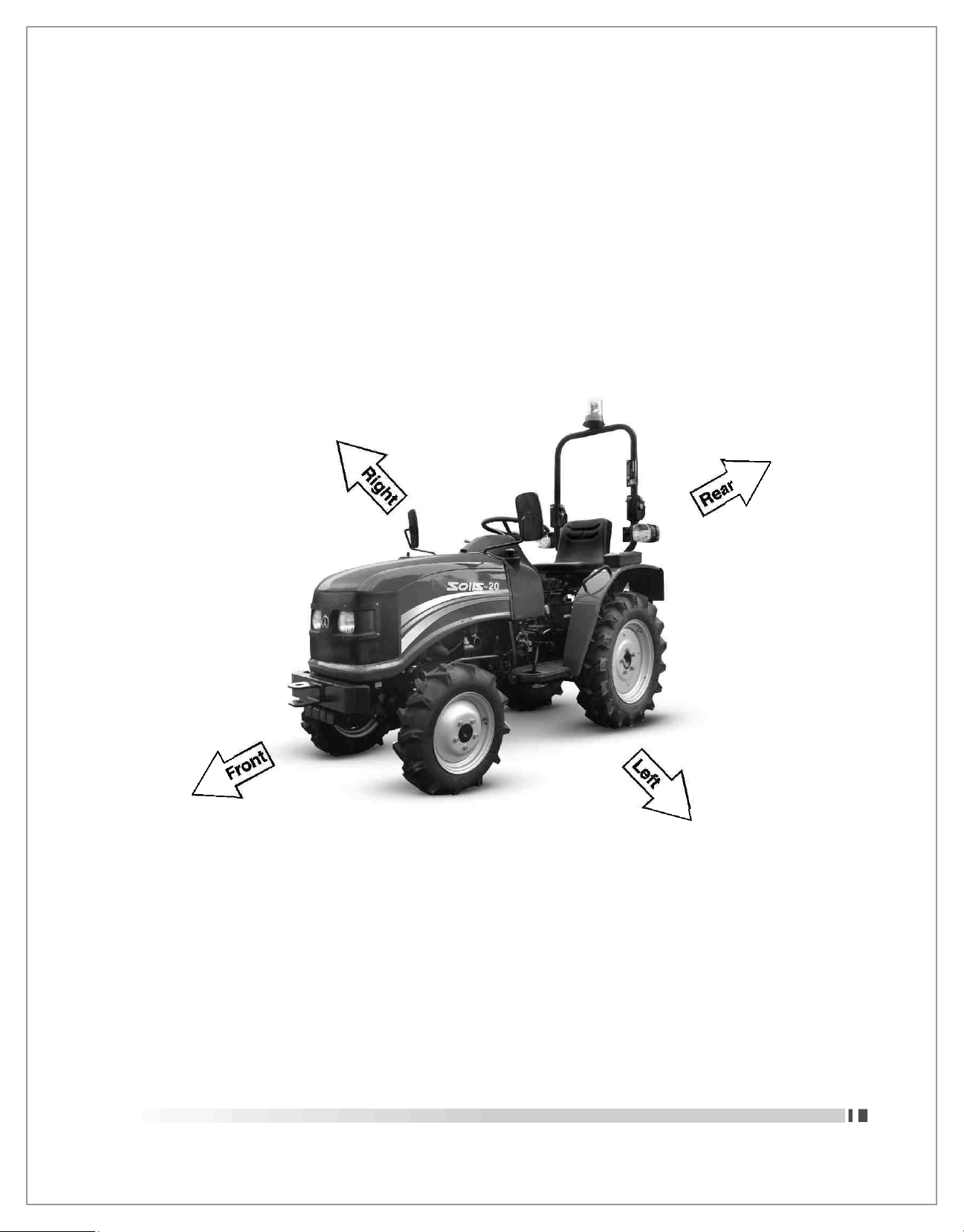
(Front, Rear
, L
eft, R
ight Portion)
T
hrough this manual
. The use of the t
erms L
EFT, RIGHT, FRONT
and REAR mu
st be
understood
, to
avoid an
y confus
ion when following the introduction
s. The LEFT
and RIGHT means le
ft
and righ
t
s
ides o
f the Tractor
when facing forward in the driver
's s
eal, Reference to the FRONT indicate
s the
radiator end o
f the Tractor,
while the REAR, indicate
s the
drawbar end
.
W
hen spare par
ts
are required, alwa
ys specify the Tractor
and engine serial number when ordering
these
par
ts. This
will facilitate faster delivery and help ensure tha
t the c
orre
ct
par
ts of
your particular
Tractor s
erial number is punched on a plate attached to the le
ft
hand side o
f the
engine bod
y. For easy
reference, we sugge
st you to
write the number in the space provided in the owner
's
personal data
.
20
SOLIS 20 OPERATOR MANUAL
Page 23
3. OPERATIONS
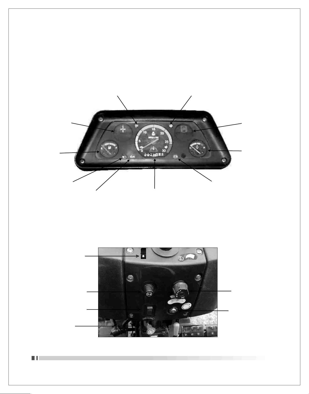
3.1 INSTRUMENT PANEL
Left Turn Indicator
Right Turn Indicator
PTO Lever Position
Indication
Fuel Gauge
High/Low Beam
Oil Pressure Indicator
Engine RPM cum
Hmr. Meter
Gear Lever Position
Indication
Temperature
Gauge
Battery Indicator
3.2 ELECTRICAL CONTROLS
Revolving Light Switch
Turn Indicator Switch
Hazard Warning Switch
Combination Switch
Ignition Switch
Pull to Stop Lever
SOLIS 20 OPERATOR MANUAL
21
Page 24
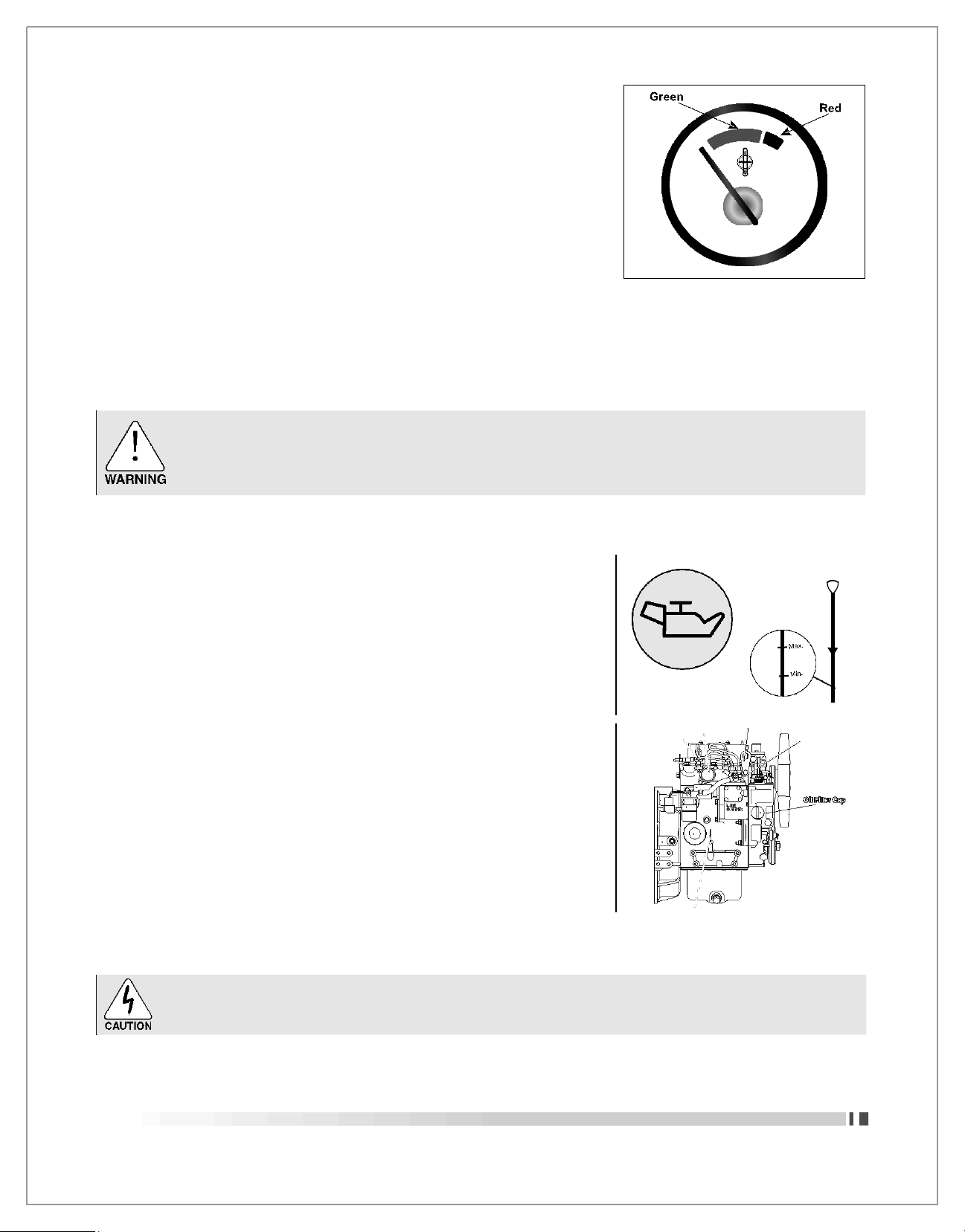
3.1.1
TEMPERATURE GAUGE :
This
gauge indicate
s t
emperature of engine coolan
t, GREEN z
one
indicates normal temperature and RED Zone indicates engine
overheating
. If the
needle moves beyond normal range
,
t
owards RED zone
, f
ollow the procedure
.
C H
1. Drive safel
y to the s
ide of road and
stop y
our tractor
.
2
. A
llow the engine to run idle
.
3
. If the t
emperature does not go down
, shut it off
and allow
suffic
ien
t t
ime for i
t to c
ool
.
4
. Vis
ually inspe
ct the fan
bel
t for
loosene
ss,
breakage and all
water hose connection
s for
lea
k.
5
. If the fan
belt i
s OK
and no coolant leak is noticed che
ck the
c
oolant level
.
6
. Add c
oolant if required otherwise conta
ct y
our neare
st
dealer
.
Do not remove the radiator cap when the engine and radiator are ho
t. B
oiling ho
t c
oolant and
st
eam may blow out under pressure, which could cause serious injur
y. The cap
should only be
taken off
when the coolan
t t
emperature has lowered
.
Necessary precaution to be taken while opening the radiator cap
.
3.1.2
ENGINE OIL PRESSURE INDICATOR
This
indicator indicates pressure of lubricating oil in the engine
. If the
indicator glow
, stop the
engine and follow the procedure
:
1
. Stop y
our tractor to the side of road on leveled surface
.
2
. Wait for suffic
ien
t t
ime after
st
opping the engine to get down the
oil from galler
y to
oil sump
.
3
. P
ull ou
t the
dipsti
ck,
wipe o
ff
oil with a clean cloth
.
4
. Insert the
dipsti
ck, f
ully into the oil level gauge guide
, t
hen pull
ou
t the
gauge again
. The c
orre
ct
oil level is between the M
AX.
&
Min. mar
ks on the
dipsti
ck.
5
. If the
oil level is low, remove the oil filler cap and add oil o
f the
specif
ied
type to the MAX. level.
6
. Inst
all the oil filler cap after a topup
.
7. Chec
k the
oil pan and other parts for oil leakage
.
8
. Start the
engine, allow i
t to
run idle and don
't race it
immediatel
y
if again the red light glow
s, t
hen conta
ct y
our neare
st
dealer
.
Do not operate the engine if there is no oil pressure indication.
22
SOLIS 20 OPERATOR MANUAL
Page 25
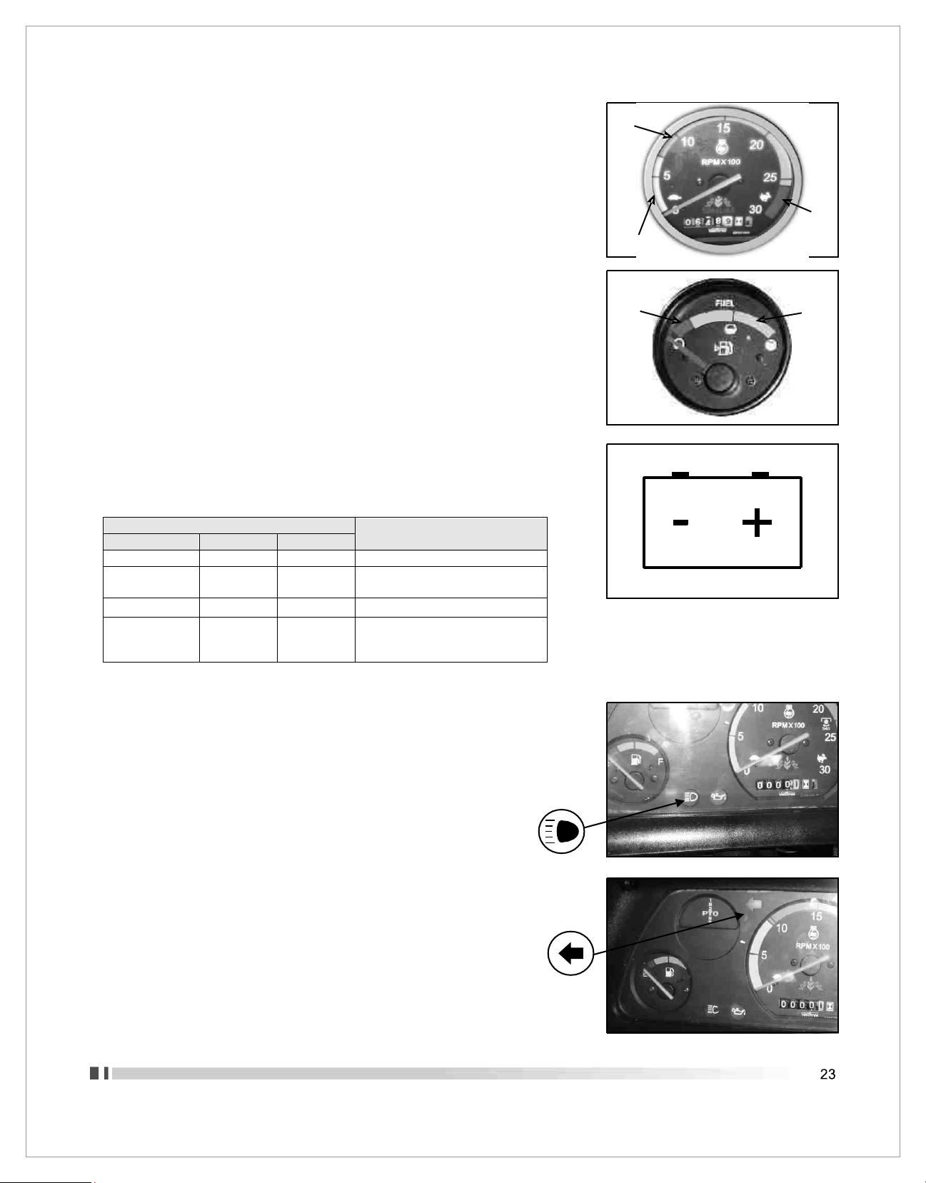
3.1.3 RPM CUM HOUR RECORDER
Green
Needle o
f this meter
indicate
s s
peed of engine in revolution per minute
and the recorder meter indicate
s the
number of hour
s clocked by the
engine
.
G
reen Zones i
s safe for
operation
.
Red
Yellow
3.1.4 FU
EL GAUGE
F
uel gauge gives an approximate indication o
f the
quanti
ty of f
uel in
f
uel tan
k. If the
needle enters in RED zone, refill the fuel tan
k.
Ens
ure Min. 5 Ltr. o
f F
uel in Fuel Tan
k to av
oid air locking
F
uel Tank Capaci
ty 30 Ltr.
Red
Green
3.1.5 BATTERY CHARGE INDICATOR
This indicator indicates that either battery is being charged or not.
Refer the below given observations with respect to different
CONDITIONS
Battery Charging
System Functioning
IGNITION SWITCH
ENGINE
INDICATOR
ON
OFF
GLOW
OK
ON
OFF
OFF
Charging System/Battery is defective,
Get both thing checked from electrician
ON
Start/Running
OFF
Battery being Charged
ON
Start/Running
GLOW
Charging System is defective/Battery
is draining out, get the charging system
checked from electrician.
3.1.6 HIGH BEAM INDICATOR
This blue light glows when Head Lights are in high beam mode.
3.1.7 LEFT SIDE INDICATOR
It glow when the left side indicator is switched ON
SOLIS 20 OPERATOR MANUAL
Page 26

3.1.8 RIGHT SIDE INDICATOR
It
glow when the righ
t s
ide indicator i
s switc
hed ON
3.1.9 PTO LEVER POSITION INDICATOR
This is
onl
y for
awarene
ss
abou
t Posit
ions o
f PTO Lever to get 3-S
peed
s
i.e. C1, C2, C3
.
1
N
2
PTO
N
3
3.1.10 GEAR LEVER POSITION INDICATOR
This is
only for awareness about Positions of Gear Lever to select the
desired gear speed
.
1
2
N
R
3
SOLIS 20 OPERATOR MANUAL
Page 27

3.2 ELECTRICAL CONTROLS
Turn Indicator Switch
Hazard Warning Switch
Combination Switch
Ignition Switch
Engine Stop Knob
3.2.1 HAZARD LIGHT SWITCH:
Purpose of the hazard switch is as follows.
1. All the four lights blinking Indicates that driver has no control on tractor.
2. Mechanical defects in the tractor.
Push this switch to blink all indicators in HAZARD situation to alert others.
3.2.2 SIDE INDICATOR SWITCH:
This switch is used for
indicating the vehicle turn. Move turn signal lever le
ft to
indicate le
ft
hand turn or righ
t for
right hand turn
. I
ndicator ligh
ts in cluster
will flash
accordingl
y.
Left
Right
3.2.3 COMBINATION SWITCH:
This switch illuminates all lights (Parking Light, Head Light, High Beam, Low Beam)
with the clockwise rotation as well act as horn switch.
HORN : Press the combination switch to blow the Horn.
OFF Position
All lights are off.
1st Position
(Clockwise)
With 1st click Stop
parking lights,
Instrument panel lights
and tail lights will glow.
2nd Position
(Clockwise) :
With 2nd click Stop
Head lights (Low
beam), Instrument
panel lights, Parking
lights and tail light will
3rd Position
(Clockwise) :
With 3rd click Stop
Head lights (High beam)
Instrument panel lights,
Parking lights and tail
light will glow.
Horn :
Press the
combination switch
to blow the Horn.
OFF
1st
2nd
3rd
Horn
SOLIS 20 OPERATOR MANUA
L
Page 28

3.2.4 STARTING KEY SWITCH:
Functioning of starting key switch is as below:
Ist Position (OFF) : All
the electrical systems
remain disconnected in
this position.
2nd Position (ON) : The
warning lights (Battery, Oil
Pressure indicator & other
Cluster Lights will be
functional in this position.
This is normal running
position after the engine is
started.
3rd Position (Use of
Heater):
Turn the key slightly
clockwise and hold in
between ON & START
position for 3-5 Seconds so
that glow plugs can heat up
the air in the cylinders.
4th Position (START):
Immediate after the
use of air heater turn
the key furthe r
clockwise to Start
position to start the
engine.
O
N H
EATE
R
START
NOTE : Do not keep the starter engaged more than 5-8 seconds. If engine stalls/fails to start then wait for 5-10 seconds
before re-engaging the starter, otherwise you may damage it.
Keep the switch in OFF condition when engine is also in OFF condition.
3.2.5 ENGINE STOP KNOB:
To stop the engine release the accelerator lever and pull the stopping
knob. After stopping the engine push it back to its original position.
3.2.6 FUSE BOX:
Fuse box is mounted under the right side of Fuel Tank. If an electrical
failure occurs, check for a blown fuse and replace with specified fuse
only.
CAUTION: Never install a wire instead for proper fuse.
3.2.7 Revolving Light Switch
Revolving light as show in the figure is used as the precession light
during working of the tractor in the field. ON/OFF switch is located on
dash board in control figure.
SOLIS 20 OPERATOR MANUAL
Page 29

3.3 ELECTRICAL EQUIPMENTS
3.3.1 BATTERY AND ITS MAINTENANCE
12,V, 50 AH is mounted at front of the tractor.
1. CHECK ELECTROLYTE LEVEL
It must be as per the recommendation of battery manufacturer.
If required top up with distilled water. Never add acid.
2. CHECK CAREFULLY BATTERY CHARGING
Protect against freezing. Insure that terminals are clean and tight. Check
electrolyte battery charge. This operation is carried out using a battery
hydrometer. The value of a fully charged electrolyte is 1265. If below 1215
recharge the battery.
3. PRECAUTIONS
1. The electrolyte in the battery contains sulphuric acid. Which is
dangerous and burn the skin take all necessary precautions (protective
clothing)
2. If accidentally splash yourself with acid, take care not to breath in
the fumes, rinse throughly and consult a doctor immediately.
3. Keep the battery well away from any naked flame or sparks
3.3.2 ALTERNATOR
Alternator is fitted on Left side of engine and generates current which
charges battery for healthy electrical back up.
Rating: 12V, 30A
3.3.3 V-BELT CHECKING AND ADJUSTMENT
CHECKING:
1. Ensure for V-Belt free from defects such as wear, cuts or surface
separations, otherwise replace with genuine specified belt.
2. Inspect belt tension as instructed below:
Push the belt downward with approx. 98 N (10kgf) (22lbf) force midway
otherwise adjust the belt tension
ADJUSTING :
1. Removal belt cover the covers V-belt.
2. Loosen all retaining bolts of the alternator and adjusting plate.
3. Insert a bar between the alternator and cylinder block and use leverage
to move that alternator to have proper v-belt tension.
4. While V-belt tension is appropriate, retighten all the retaining bolts of the
alternator and adjusting plate.
5. Reinstall the belt cover.
3.3.4 STARTER MOTOR
Starter motor is mounted on the left side of the engine.
• The starting motor rotates the engine crankshaft for starting.
• Capacity and Rating: 12V, 1.8KW
SOLIS 20 OPERATOR MANUAL
Page 30

3.3.5 GENERAL MAINTENANCE OF ELECTRICAL SYSTEM
Never Patch up the electrical circui
ts.
Never replace a blown fuse by a higher capaci
ty fuse. It c
ould
cause a
f
ire
.
Never work on componen
ts such as the alt
ernator or
starter motor
when
the
engine is running
.
Lastly when
you
are
c
leaning
the tractor
and using
the
pressure
s
pra
y, take c
are no
t to
damage
the c
onnections on
the v
ariou
s
electrical cable
.
3.3.6 PRECAUTIONS BEFORE CONNECTING WELDING
APPARATUS:
•
In case of any electrical welding on tractor, first disconnect battery
earth connection.
3.4 SHEET METAL
3.4.1 PROCEDURE TO OPEN THE TOP HOOD
Press the knob (at the centre of the bonnet) towards steering wheel and lift
the bonnet upwords to full open position.
SOLIS 20 OPERATOR MANUAL
Page 31

L
ock
3.5 CONTROLS
2WD & 4WD Lever
Differe
Lever HI
PTO Lever
Main Gear
Dipstick
Shifter Lever
3.5.1 MAIN GEAR SHIFTER LEVER
Main gear shifter lever enables to get the required speed (6 Forward and 2
Reverse) by selecting the particular gear with combination of hi-low gear
lever. Refer photo for gear shifting arrangements.
Before changing the tractor movement from forward to reverse or reserve to
forward direction wait for the tractor to stop.
Release accelerator pedal and declutch. Select required gear, release the
clutch gradually and accelerate the engine.
NOTE: When traveling downhill always remain in gear. Never declutch. The gear selected should be same as would be
used to climb. For engaging/disengaging gear always depress the clutch
3.5.2 HIGH-LOW LEVER
This lever is used to change the low speed into high speed or vice versa when
tractor is moving. According to requirement you can use it with combination
with main gear lever.
Speed Selection:
1. Neutral Position: Lever in the middle cut
2. High Speed: Move the lever out of the cut and shift towards rear end.
3. Slow Speed: Move the lever out of cut and shift towards front end.
Select the speed before tractor movement.
3.5.3 2WD/4WD LEVER
This lever decides whether tractor move in 2WD or 4WD mode.
2WD MODE: By engaging the lever in 2WD position the power is transmitted
to rear wheels only. Shift the lever towards rear (driver seat) to select 2WD
mode.
4WD MODE: With the lever in 4WD position the power is simultaneously
transmitted to all 3 wheels (Front & Rear) of tractor. Shift the lever towards
front to select 3WD mode.
NOTE: 4WD Mode is for field operation and 2WD mode is for road running.
SOLIS 20 OPERATOR MANUAL
4WD
2WD
Page 32

3.5.4 POWER TAKE OFF SHIFTER LEVE
R
T
here are three position
s for PTO lever. In the 'N' it is c
alled Neutral position
.
and other three speed are also selected b
y shift
ing this lever to particular
position
PTO Lever Position
PTO RPM
@engine rated RPM
1
630
2700
2
930
3
1605
3.5.5 D
IFFERENTIAL LOCK PEDAL
W
hen you pre
ss
pedal differential lo
ck
will work and both the wheel rotate a
t
s
ame speed
.
Note : Differential lock operation should be in straight position only and
should be disengaged at turnings to avoid any damage of differential
assembly.
Do not apply differential lock while tractor speed is more than 6 kmph
on turning.
3.5.6 CLUTCH
PEDAL
By
pressing clutch pedal the motion and power or engine will be disengage
f
rom gearbo
x.
Release the clutch pedal slowl
y for t
ransfer the engine power
to
gear bo
x.
3.5.7 METHOD
TO CHECK CLUTCH PEDAL FREE PLAY
Press down the clutch pedal and measure the distance between the footrest
and pad. The distance should be 25 to 30 mm. If the distance is less than
25 mm or higher than 30mm then get it adjusted.
NOTE: Do not keep foot on clutch pedal while tractor is in running condition. It may cause excessive wear of clutch
and clutch falls before its life time
3.5.8 FOOT
BRAK
E PEDALS
Use independent brake in the field operation
s. In f
ield you will turn more
s
harply by pressing brake pedal for the side wheel on the turn
. The
pedal
s
mu
st be locked for
road use
.
3.5.9 METHOD TO CHECK BRAKES
Release the hand brake. Uncouple the two pedal
s
Press
down
the
right hand pedal and measure
the distance bet
ween
the
pad
s & footrest. The distance s
hould be between 25-30 mm
.
If the f
ree play is le
ss t
han 25mm or higher than 30mm then adju
st the both
hex nut on actuator tie rod until free pla
y c
ome
s to 25 to 30 mm.
Now, pre
ss
down the le
ft
hand pedal
. If the v
alues are not equal with the right hand pedal
t
hen repea
t the s
ame procedure until values come equal
.
N
OTE: Ens
ure locking of both break padles while driving on road
.
Note: Difference in the free play will lead to unbalanced brake
s. the tractor can s
lew, in the event o
f v
iolent braking
. the
wheel on which the brakes are applied lo
cks
and the
tyre
wears out quickl
y.
During Road Operation
s Both the
brake
P
edal
s s
hould be locked
SOLIS 20 OPERATOR MANUAL
Page 33

3.5.10 PARKING BRAK
E
Park
ing brake lever is mounted on R.H
.S. foot
board and should alwa
ys be
engaged while tractor is parked
.
Press the foot
break pedal and shi
ft the
parking brake lever towards driver
seat to
engage the parking brake
.
Press the foot
break pedal and shi
ft the
parking brake lever toward
s f
ron
t to
release the parking brake
.
3.5.11
FOOT
ACC
ELERATO
R
Foot acc
elerator is used for control the tractor speed as per requiremen
t,
Only use foot acc
elerator while moving on road
.
3.5.12 HAND THR
OTTLELEVE
R
Hand throttle lever mounted on dashboard (Panel) is used in field application
to inc
rease the speed of engine, pull down the lever and to decrease pull up
the lever.
3.5.13 DR
IVER SEAT
Driver sea
t can be
adjusted according to your convenience in following wa
ys
3.5.14
SEAT PAN TRAVEL
ADJUSTMEN
T
Seat can be moved f
orward
& back
ward to three different locations as per
requiremen
t. A
dju
st the seat as
per requirement b
y shift
ing the pin as indicated
direction
.
3.5.15
SEAT
BACK ADJUSTMEN
T
Seat can be
adjusted upward/downward by loosening the four bol
ts
mounted
on the ba
ck s
ide o
f the seat.
Loose the four mounting
sc
rews o
f seat back. S
lide the seat ba
ck to des
ired
height and religh
t the sc
rew
s.
3.5.16
TOOL BOX
T
ool box is mounted at below of driver sea
t.
To
open the tool bo
x tilt the seat t
oward
s f
ron
t t
hen unscrew then knob (A) and
li
ft the cover of t
ool bo
x.
SOLIS 20 OPERATOR MANUAL
Page 34

3.5.17
SEVEN PIN SOCKET
7 Pin socket is mounted on ba
cks
ide of driver sea
t to attach the t
railer
c
onnection as per following Connector
s.
1
Eart
h 2
Work
ing ligh
t
3 Le
ft I
ndicator
5 Righ
t I
ndicator
7
For Extra
Connection
4
Park
ing ligh
t
6
Brake
ligh
t
3.5.18
POSITION CONTROL LEVE
R
This
bla
ck c
olour lever is mounted on R.H
.S. of
driver seat which enable
s
raising or lowering the implement/li
ft.
3.5.19
POWER TAKE OFF
P
ower take o
ff is
mounted at rear side o
f tractor. This is used for s
upplying
power directl
y to
implemen
t f
rom engine
. P
ower take o
ff shaff has st
andard
06 Spline on 540 rpm
. PTO can be
engaged or disengaged b
y PTO shifter
lever. 3 - speed
s can be obt
ained by putting the
PTO Lever in diff
eren
t t
hree
.Posit
ion (i.e. 1,2,3)
3.5.20 R
EGISTRATION PLATE
A v
ehicle registration plate or number plate is mounted at rear end of righ
t
f
ender as per country rule
.
3.5.21
LIGHTS
The v
ehicle is equipped with
E
marked front and rear tail ligh
ts.
SOLIS 20 OPERATOR MANUAL
Page 35

3.6
Engin
e:
3.6.1 S
tart
ing the Engin
e:
Starter Switch: The starter switch is used to start the
engine
OFF POSITIO
N
W
hen the key i
s t
urned to this position, power suppl
y to the
electri
c circuits is
cut off,
and the ke
y can be
removed or inserted in this position
. To stop the
engine
, t
urn the ke
y to this posit
ion and pull the
'P
ull to
stop k
nob
'
ON:
W
hen the key i
s t
urned in to this position, power i
s s
upplied to the
electri
c circuits. After the
engine
starts , the key is
held in thi
s
position
.
HEAT:
This is an int
ermediate position between
the 'ON'
and
'Start'
position
. W
hen the key i
s t
urned to this position
, the
glow plug
s
would become hot and allow ea
sy startup of a c
old engine
.
START:
W
hen the key i
s t
urned to thi
s f
inal position
, the starter c
ran
ks the
engine and
the
engine
starts. W
hen
the key is
released, i
t
automatically return
s to the 'ON' posit
ion
.
For S
tart
ing
:-
A
Che
ck that the
gear shifter lever and range selector lever are in neutral
.
B
Move the low/ high speed selector lever to neutral position
.
C Move the hand throttle lever to about halfway position
.
D Depre
ss the clutch
pedal all the wa
y.
Warning: The E
ngine Should not Crank i
f the
above conditions are not met -
If this
happens have
the tractor
repaired b
y y
our dealer or
authorized service center
.
Cold Weather
start
ing (Temperature below 0 °C or 32
° F):
W
hen outdoor temperature drop
s to
around or below 0 °C (32
° F),
check the c
ooling
system
and if necessary add the recommended
antifreeze
.
Warning: Do not
inje
ct f
luids (Ether) to make the engine easier to
start in c
old
weather
.
3.6.2
. Pro
ceed as
Follow
s:
1 Perform operation
s A, B,C
and D as instructed above
.
2 Turn the
Starter Key to '
Hea
t' posit
ion and keep i
t t
here for few second
s
and then turn the ke
y to start posit
ion
.
3
If the
engine fail
s to start
repea
t Step 2,
wait a further 10 to 15 seconds and
t
hen turn the ke
y to start posit
ion again
.
Note:
1
If the
engine fail
s to start after two or t
hree attemp
ts
and smoke can be
s
een coming out o
f the ex
hau
st,
repea
t the start
ing procedure with le
ss
t
ime glow plug heater
.
2 Do no
t k
eep the ke
y t
urned to
start posit
ion for more than 15 seconds at a
t
ime
.
SOLIS 20 OPERATOR MANUAL
Page 36

3
Wait at
lea
st
one minute between ever
y two att
emp
ts of start
ing the
tractor.
If the
engine does no
t start
regularly and easil
y, do not cont
inue a
s for you may
run down the batter
y. B
leed any air that may have accumulated in the fuel
system
and, i
f the
problem persi
sts check that:
1 Fuel filters are not blocked
2 The battery and Heater Plugs are working efficientl
y.
Note-: Before
start
ing a cold engine in cold weather fir
st cover the
radiator with
a radiator cover. Remove the cover a
s s
oon as a normal working temperature
is achieved
.
3.6.3. R
unning in:- It is essent
ial to take the following precautions during the
running in period
:
1 During this period, do no
t s
ubje
ct the tractor to
loads greater than those i
t
will have to deal with during the re
st of its
working life
.
2 Engage low gears when towing hea
vy
load
s.
3
W
hen running in
, check
regularl
y that
all
sc
rew
s, nuts
and bol
ts
are tigh
t.
4 To ensure prolonged clutch life, run in the clutch di
scs c
orrectl
y.
3.6.4
. Turning off the engin
e:
1 Turn the engine accelerator to idle position
2 Turn the starting Ke
y to 'Off' posit
ion
3
Stop the
engine by pulling the fuel cut-o
ff lever t
ill engine
stops.
3.7
FUELSYSTE
M
3.7.1 FU
ELSAVING TIPS
Maintain your tractor
. B
adly maintained tractor wastes 25% of preciou
s f
uel
.
A
lwa
ys top up tank at the
end of da
y to av
oid water contamination in fuel tan
k
due to moisture
.
Change fuel filter regularly as per maintenance
sc
hedule. Use genuine fuel
filter av
ailable at authorized dealer
. Also c
lean feed pump
, filter
and drain ou
t
water from filters as per
sc
hedule
.
Prevent f
uel leakage
.
For better
performance o
f tractor f
ollow running in proce
ss
mentioned in thi
s
manual
Do not ride the clutch
.
Run tractor with appropriate speed and gear combination
.
Do lengthwise field operation
.
A
lwa
ys k
eep the specified
tyre
pressure for road and field operation
.
Switch off the
engine when the tractor is not in use
.
Av
oid wheel slippage
Attac
hed tractor trolley at appropriate heigh
t.
Do not over load tractor beyond capaci
ty.
34
SOLIS 20 OPERATOR MANUAL
Page 37

3.8 HYDRAULIC
3.8.1 HYDRAULIC
SYSTE
M
In this tractor live hy
drauli
c system is
provided
. In
which hydraulic pump i
s
driven by engine and mounted a
t cover of
engine
. As the
engine run
, the
hydraulic pump also
starts
working
. T
ransmission lubrication oil is used a
s
hydraulic oil
.
3.8.2 T
RAN
SPORT LO
CK
It acts as safely device
during transportation of implemen
ts. It is located on f
ron
t
s
ide of Hydraulic Rear Cover below driver sea
t.
Use
: For safety lock f
ull
y t
ighten the response valve by rotating in clockwise
direction
Response Valve should always be closed during implements transportation.
3.8.3 THREE POINT LI
NKA
GE
T
hree-point linkage is used to moun
t the
implemen
t,
which i
s f
ully mounted
,
or semi-mounted and used for differen
t f
ield operation
. T
hree-point linkage
i
s cont
rolled by hydraulic lever
. In this two
lower link are available, of which
one side o
f the
lower link is attached with differential housing and other i
s
used to hitch the lower pin o
f the
implemen
t. Lift
rods are mounted on li
ft
arm
that is
operated
t
hrough ro
ckshaft.
Loose
s
ide o
f Top
link is used
for
attaching upper hitch pin of implemen
t. Top
link is adjustable for proper
sett
ing of implement and ease a
t the t
iming of joining
.
3.8.3.1
LIFT RODS (A &
B)
If lift
rod i
s fitted with lift
arm and lower lin
k, the
length of li
ft
rod (
A&B) c
anno
t
be adjusted
.
3.8.3.2
TOP LINK
(C)
For
length adjustment o
f top
lin
k, fix the top
link other end and turn the lever
for inc
reasing or decreasing the length. During field operation lo
ck the t
ube
to av
oid unnecessar
y t
urning
.
3.8.3.3
LOWER LINKS
(C)
Lower Lin
ks
are provided for hitching the implemen
t.
3.8.3.4 ATTACHIN
G IMPLEMENT TO 3 POINT LI
NKA
GE
Posit
ion the tractor to align corresponding linkage with the hitch poin
ts of
implemen
ts. K
eep the implement on hard
& lev
eled surface and attach a
s
per given below instruction
s :
First attach with Left
lower link (E) and Right Lower Link (F)
T
hen at Last attach with Top Link (C)
3.8.3.5 DIREC
TIONAL CONTROL VALVE
(DCV)
The tractor is
equipped with single acting directional control valve
. The
operator is with a lever located on LHS of driver sea
t. And the c
oupler (qui
ck
attach) is at rear side o
f tractor.
Use only single action cylinder implement.
SOLIS 20 OPERATOR MANUAL
Page 38

TYRE
TYRE SIZE
Pressure
(kPa)
80 100 120 140 160
REAR
8 - 18
4 Ply
Rating
345 395 440 480 520
FRONT
5 - 12
115 135 150 160 175
3.9 WHEELS AND TYRES
Tyres Play vital
role in transportation and agriculture operation
s. It is the most
importan
t factor in the effic
ient performance
o
f tractor it s
hould be used only as per company recommendation. Here we will discu
ss
only pneumati
c tyres.
On any tyre t
here i
s s
ome marking which represen
ts its size & c
apaci
ty e.g. Tyre
marking is 8x18, 4 ply rating i.e. 8 inch i
s
the sect
ion width, 18 inch i
s the
bead diameter
. Ply rat
ing doe
sn’t s
how tha
t the s
ame No. of plies are inserted in
tyre. It is
onl
y c
omparative measure o
f the
load carrying capaci
ty (L.C.C) of tyre. As
more ply rating shows more L.C.C. a
t the s
ame
t
ime as L.C.C. increase the sho
cks abs
orption capaci
ty dec
rease
s.
In
general
, tractor is cons
idered for two
types of
wor
k:
Work on soft s
oil where maximum adhesion is needed
. In this case t
here will be use of lowe
st
pressure compatible with the
load carried
.
Work on
hard ground and road
s, t
owing e
tc. In this case t
here will be use of maximum pressure
.
3.9.1 IN
FIELD OPERATIONS
(Recommended
Tyre Press
ure
: F
ront - 1.75 Kg/cm
2
&
Rear .84 Kg/cm2)
Correct Pressure
G
ood adherence by dirt grouser
s.
G
ood cleaning o
f the t
read
Insufficient P
ressure
Reduce adherence through la
ck of
tyre
grip
.
Deterioration o
f tyre cas
ing b
y
tract
ion force
s.
O
ver Pressure
Reduce group due to la
ck of
c
leaning
Deterioration due to compacted
ground
.
3.9.2 ON ROAD
OPERATIONS
(Recommended
Tyre Press
ure
: F
ront - 2.15 kg/cm
2
&
Rear 1.57 kg/cm2)
Correct Pressure
Resistance to Wear
Insufficient P
ressure
Reduce adherence through la
ck of
tyre
grip
.
Deterioration o
f tyre cas
ing b
y
tract
ion force
s.
O
ver Pressure
Reduce group due to la
ck of
c
leaning
Deterioration due to compacted
ground
.
3.9.3 RECOMMENDED
LOAD
CARRYING CAPAC
ITY
NOTE: Tyre pressure should never maximum pressure as recommended the tyre could burst. Change / repair any worn
or faulty tyre (cuts, cracks etc.) immediately to prevent the problem become more severe
SOLIS 20 OPERATOR MANUAL
Page 39

3.9.4 BALLASTING OF TRACTOR
P
roper ballasting is an importan
t factor in tractor
performance
. For better
performance o
f tractor, the
weight o
f tractor can be dec
reased as per
requiremen
t. Max
imum productivi
ty can be ac
hieved only i
f tractor
weight i
s
appropriate for the job
. B
alla
st is
required for traction and
st
abili
ty. F
ollowing
factors det
ermine amount of balla
st.
S
oil surface loose or firm
Type of
implemen
t
Travel s
peed and tractor power output partial or full load
.
3.9.5 FRONT WHEEL TOE IN
After sett
ing the tra
ck
width is necessar
y to
adju
st toe in of the f
ront axle
.
3.9.6 CHECKING AND ADJUSTMENT OF TOE-IN
Firstly
par
k the tractor on level surface. T
urn the
st
eering wheel so tha
t f
ron
t
wheels are in the
st
raight-ahead position
. Stop the
engine. Measure distance
(A) between tyres at hub level in front of axle. Record measurement and
mar
k the
points on
tyres. Move tractor back
about 1 meter so that mark on the
tyre is at
hub level behind the axle
.
A
gain measure distance between
tyres at s
ame point on
tyre. Rec
ord the
measurem en
t. Det
ermine
the diff
erence between
f
ront and rear
measuremen
t. If the f
ront measurement i
s s
maller toe i
s 'In'. If the
rear i
s
s
maller
, toe is 'Out'. DIstance (A) at f
ront or tyre
s s
hould be 3-6 mm le
ss t
han
distance measured at rear o
f tyres.
A
dju
st t
oe-in
If necessary. For
adjusting toe-in loosen the lo
ck nuts (B) on
both side
s. T
urn the tie rod and adju
st toe in to
3-6 mm
.
SOLIS 20 OPERATOR MANUAL
Page 40

3.9.7 REAR WH
EEL T
RACK
WIDTH
ADJUSTMEN
T
Track
width o
f the
rear axle can be adjusted by repositioning or exchanging the rims or by reversing the wheel di
scs.
Track
width can also be adjusted by exchanging the complete wheel to the opposite side o
f tractor. This
manual permi
ts
the c
hange from di
sc dis
hed in to di
sc dis
hed out operations without disassembling the wheel
. W
hen changing rear
wheel
s f
rom one side to the other
, the
arrow on sidewall o
f tyre
poin
ts in the
direction o
f f
orward rotation
. A study of
f
ollowing diagram
, f
rom attempting to change tra
ck
width setting will save unnecessary labour
.
DIAGRAM
(REAR)
(FRONT)
Trouble Shooting (T
yre Complaints)
T
RACK
WIT
H
(725 - 860) MM
(520 - 103) MM
Probl
ems F
actor Effect
ing
Corrective act
ion
Alternate wear
trea
d
I
nappropriate pressure in
tyres.
Continuous use o
f tyres for excessive
load on
road with two-tyre trailer
.
Inc
orre
ct matc
hing o
f tractor with t
railer
.
Maintain appropriate pressure in
tyres.
T
here should be che
ck up of tyres
pressure from
t
ime to time
.
T
here should be corre
ct matc
hing o
f tractor wit
h
Sidewall or
Shoulder d
amage
Damage b
y s
harp edge
s t
hings like
st
one
s,
pieces of gla
ss etc.
Tyres
damage with linkages while turning
.
Maintain appropriate pressure in
tyres.
Never turn the tractor instantl
y.
Scoop or w
ear
from
high cen
ter
Excessive
pressure led to early wear o
f tyres.
Use o
f tractor in t
ransportation for longer period
.
P
roper inflation and ballasting o
f tyres
during
Puncture of
tyre
aga
in and again
:
Places where Crops like Sunflower, Sugarcane &
Cotton etc that are with sharp edges stem and
deeps roots have more probability to cause
damage to tyre.
To over come this problem, wheel track should be
Damage t
o
tread/cr
own of
tyre
Merging of sharp edges things in tread/crown
area.
Contact with stones, pieces of glass, steel or crops
with sharp edges stem and deep roots etc.
Don’
t
run the tractor with high speed on sharp
edges area
s.
Damage of tyre
due to l
ess
Less inflation pressure of tyre.
Overload
According to the load, pressure should be there in
tyres.
3.9.8
GENERAL SUGGESTIONS
Always maintain proper inflation of tyres.
Tyre should be ballast to over come the problem of slippage.
Tractor should be park in shed area in order to avoid the direct contact of sunrays with tyres.
If tractor is not in use for longer period then tyre should be jacked
Avoid the contact of oil & grease with tyres.
3.9.9 CHECK WH
EEL NUT BOLT
Check wheel nut of the front and rear wheel. Torque it as per specification.
Wheel body on hub
Rear wheel : 130-130 NM
Front wheel : 72 NM
38
SOLIS 20 OPERATOR MANUAL
Page 41

4
. GENE
RAL MAINTENANC
E
4.1ENGINE
4.1.1 ENGINE L
UBRICA
TION SYSTE
M
We rec
ommend the grade
SAE15W 40 as
mentioned in service
sc
hedule
.
4.1.2 CHECK ENGIN
E OIL LEVEL
Bef
ore checking the oil level be ensure tha
t tractor is
parked on leveled
ground
. Stop the
engine and wai
t for s
ome time, as all oil should return to
oil sump
.
Che
ck the
oil level by unscrewing dipsti
ck (A) Top up the
oil level i
f the level
is below the minimum level mar
k. Do not over f
ill than maximum level mar
k.
4.1.3
CHANGIN
G OF OIL FILTER & ENGINE OIL
CHANGIN
G OIL FILTER (Spin-on typ
e):
1
. Stop y
our tractor to the side of road on leveled surface and drain
the
engine oil in an oil pan after removing the drain plug
.
2. Remove the oil filter by rotating it in anti-clockwise direction b
y
hand or with the filter wrench
.
3
. Take
new oil filter and che
ck it for
proper seating of gaske
t.
4
. A
ppl
y c
lean engine oil to gasket on the new oil filter
.
5
. Inst
all oil filter
. W
hen the filter gaske
t contacts the
mounting
surface of filter, t
ighten the new oil filter
.
R
EFILLING ENGINE OIL
:
1. Re-install the Drain plug and remove the oil filler cap
.
2
. F
ill the engine oil with the specified engine oil (
SAE 15W
40) to
the specif
ied level to sump capaci
ty. (3.1 Ltr.
)
3
. Insert into the
oil level gauge guide
, t
hen pull ou
t the
gauge again
.
4
. Ens
ure that oil level should be between the M
AX. & MIN.
mar
ks
on
the
oil level gauge
. If less t
hen pour the oil to bring i
t to specif
ied
level
.
5
. Inst
all the oil filler cap after a refill
.
6. Che
ck the
oil pan and other par
ts for
oil leakage
.
7
. Start the
engine, allow i
t to
run idle and don
't race it
immediatel
y.
SOLIS 20 OPERATOR MANUA
L
Page 42

4.1.4 CHANGIN
G OF FUEL FILTER (Spin-on type)
1
. Shut
down fuel co
ck.
2. Remove the filter by rotating it in anti-clockwise direction b
y
hand or special wrench
.
3
. Take
new filter and che
ck it for
proper seating of gaske
t.
4
. A
ppl
y c
lean engine oil to gasket on the new fuel filter
.
5
. Inst
all fuel filter, when the filter gaske
t contacts the
mounting
surface of filter, t
ighten the filter and ensure tha
t t
here is no
leakage
.
4.1.5 AIR B
LEEDING FROM FUEL INJECTION SYSTEM/ FUEL
FILTER REPLACEMENT
After c
hanging the fuel filter the
system must be
air - bleed in thi
s
manner
:
1
.
Switch ON the ignition key to start the electric pump till completion
of air bleeding process.
2
.
Loosen the vent plug (A) at the top of fuel filter body.
3
.
Tighten the vent plug (A) untill the bubble free fuel flows from the air
vent plug hole.
4
.
Loosen the return valve (B) of FIP and allow the air to flow out from
the system.
5
.
Tighten the vent plug (B) untill the bubble free fuel flows from the
return valve.
6
.
Loosen the injector pipes (C,D,E) and crank the engine till the
bubble free fuel flow is ensured.
7
.
Tighten all the injectors.
4.2 AIR CLEANER
4.2.1 OIL BATH TYPE AIR CLEANER
Tractor is fitted with two st
age (pre cleaner (A) and oil bath
type
air
c
leaner (B) air filtration
system.
If the dust enter in the
engine with the air it will cause wear o
f v
ariou
s
moving par
ts of
engine
, t
herefore should be cleaned and serviced
depending upon the operating condition
s.
Under extremely du
sty
c
ondition
s the t
ime limit recommend for cleaning should be
decreased
. P
roper maintenance o
f the
air cleaner extend
s the life of
the
engine. Here the air impinges upon the surface fo the oil and
particles o
f f
oreign matter are carried into the oil b
y t
heir own
momentum and trapped
.
4.2.2 CLEANING OF PRE-CLEANER (DRY)
The funct
ion of pre-cleaner i
s to
remove the du
st/waste
particle
s f
rom
air before entering the air cleaner
.
1. Unscrew the cover nut (C)
2. Remove the cover(D)
3
. Take out the Glass
bowl(E), Clean it and reassemble in reverse
procedure
.
SOLIS 20 OPERATOR MANUA
L
Page 43

4.2.3 AIR CLEANER B
OWL & ELEMENT CLEANING (WET
)
1. Remove the oil pan after opening three clamp
s.
2
. Take out the
oil filter element and immerse it in cleaning solvent and
rinse wash
. T
hen dr
y the
element with compressed air
.
3. Drain the oil from the oil pan
. Sc
rap out all the accumulated sludge and
rinse in cleaning fluid
.
4. Refill the oil pan to the marked level with 200ml oil
.
5. Reverse the removal procedure to reinstall i
t.
4.2.4 A
FTER EVERY 50 HRS
Replace air cleaner oil and clean wire mesh elemen
t.
Remove the wire
mesh filter elemen
t c
lean it with diesel or kerosene. Dry well before
assemble i
t.
Ens
ure proper seating or Rubber Rings. Replace if damage
.
SOLIS 20 OPERATOR MANUA
L
Page 44

4.3 RADIATOR
4.3.1 C
OOLANT LEVEL IN
RADIATOR (HOT)
S
lowly unscrew the radiator cap up to the safe
ty catch
(about 1/3
t
urn)
. Wait to
allow the
st
eam to escape. Continue unscrewing the
cap,
pre
ss it
down firml
y to
release the safe
ty catch. The level of
c
oolan
t s
hould ju
st touch the tab located in the f
illing spou
t.
If the level has
dropped
, check the ent
ire cooling
system for ext
ernal
leakage (radiator, hoses e
tc.) If t
here is no external leakage
, top up
the c
oolan
t.
F
ill the reserve tank with coolant upto the FULL line mar
k for c
oolan
t
TOP UP.
C
oolant is mixture of w
ater a
nd
recommended anti sca
ling /
anti rust
ing / anti
freeze agent
in
recommended rat
io,
as describe
d below
:
Recommended Anti
Sc
aling
/ Rusty (VEEDOL ZEROR)
300ML
Use of antifreeze (%) in case of operation in sub Zero Temperature
Ambient Temperature
Range0C (0F)
Upto
-15 (5)
- 15 to
-23 (-11)
- 23 (-11) to
-36 (-32)
-36 (-32) to
-33(-35)
Antifreeze (%)
30 30 50 55
4.3.2 RADIATOR DRAINING &
FLUSHING (When Cold
)
1. Remove the radiator cap and drain plug
.
2. Le
t the c
oolant drain ou
t.
Close drain co
cks
and plug
s. Flush the
c
ooling
system with water /
Cleaning Solution for 15 minutes a
t
engine oil
, t
hen drain the cleaning solution
.
3. Refi
t the
drain plug and refill the coolant (Mixture of water
,
anti
sc
aling agen
t, antif
reeze) as mentioned in 4.3.1
.
4. Run the engine with radiator cap open and depre
ss acc
elerator
2-3 times and Top up coolant if required
.
5. Refi
t the
radiator cap and ensure tightne
ss
all the connection
s
for any
leakage
.
4.3.3 RADIATOR
FINS CLEANING
1
.
Check Radiator Fin
s for
holes or cra
cks for chock
ing
.
2
. To c
lean the radiator from engine side to outside blow
c
om
4.3.4 RADIATOR CA
P
Cooling
system is closed
pressurized
system so
don
't
operate the
tractor wit
hout radiator cap or cap with damaged rubber
s
eals/defective release valve to avoid water lo
ss
and engine
overheating
.
Use genuine radiator cap onl
y.
SOLIS 20 OPERATOR MANUA
L
Page 45

4.4 HYDRAULIC
4.4.1
T
RANSM
ISSION/HY
DRAULIC
OIL LEVEL
To check the T
ransmission/Hydraulic oil level unscrew the dipsti
ck
(which
is mounted on R.H
.S. of
main gear shifter lever). Che
ck the
oil level and
TOP up if
needed
.
Note
: K
eep the oil level up to maximum oil level mar
k.
4.4.2 CHAN
GE T
RANSM
ISSION OIL
Bef
ore draining
the
oil, heat up by running engine
, t
ransmission and
hydrauli
c system. Park the tractor on level
ground
, t
urn o
ff the
engine and
t
hen drain the oil by opening the drain plug provided at bottom of gear bo
x
and differential housing
. F
ill the new oil. Che
ck the level by
dipsti
ck.
T
ighten the drain plug
.
Hydrauli
c + T
ransmission Oil capaci
ty 15.7 Ltr.
(approx.)
G
rade
: EP
-80
4.4.3 CHAN
GE STEERING GEAR BOX OIL
Drain ou
t the
oil by removing the side plate o
f st
eering gear box assembl
y.
K
eep oil level up to level plug
.
St
eering Oil capaci
ty
500 ml (approx.)
4.4.4
FRONT AXLE OIL LEVEL
Oil level check
plug is provided on R.H
.S. of f
ront axle
. O
pen the plug and
check the
oil level
. The
lower point of plug should be immersed in oil
.
Capaci
ty :2.0 Ltr.
G
rade
: EP
80
SOLIS 20 OPERATOR MANUA
L
Page 46

5
. OTHERS
5.1 (A)
TE
CHNICA
L P
ARAM
ETERS : SOLIS - 20
DESCR
IPTION OF ENGINE
Make
MHI-
VST
Diesel Engine
s Pvt. Ltd.
Ty
pe
4
stroke, Nat
urall
y As
pirated, Liquid Cooled
,
IDI,
Diesel Engine
Model and Identification
MVL3
E
Intake syst
em
Natural
As
piration
Work
ing principle (Four/Two
strok
e)
F
our
Strok
e
B
ore
/Strok
e(mm)
76/70 mm
Number and layout o
f cy
linders and firing order
03 no. o
f cy
linder
s; I
nline Layou
t; F
iring order 1-3-2
Cylinder capaci
ty
952
cc
Compression ratio (Speci
fy the t
olerance)
23:1
± 0.
5
A
rrangement o
f valves
Ov
erhead, inline
I
njection timing
170
± 10 BT
DC
I
njector
s O
pening Pressure
13.7 (+1.3) MPa
Type of Gov
ernor
Mechanical
Make(s) Country or origin
M
ITSUBISHI HEAVY I
NDUSTR
IES LTD. (JAPA
N)
E
ngine Rated speed
2700rpm
Fly
up
2970
± 50
rpm
Low Idling
1000
± 30
rpm
HP at rated RPM
18.22
Ma
x T
orque (Nm)
52.3Nm@2600 RPM
VALVE CLE
ARANCE (C
old / Ho
t)
Intake / Ex
hau
st
(mm)
0.25
L
UBRICA
TION SYSTE
M
Description o
f systems
Force F
eed-Cum-Splash
Posit
ion of lubricant reservoir
Oil s
ump at bottom o
f E
ngine blo
ck
Type of
lubrication Pump
G
ear pump
Capaci
ty of
pump at rated (Engine/pump) rpm
14 Lpm at rated speed
pressure release seating Kpa
/ (Kgf / c
m2)
294
± 29.4 kPa (3.0 ± 0.3 kgf/c
m2)
Oil s
ump capaci
ty (I
)
3.1 Liter
s
Total
Lub
. Oil c
apaci
ty (I
)
3.6 Liter
s
C
OOLING SYSTE
M
liquid
/
air cooling
Liquid Cooling
Characteristi
cs of
liquid-cooling
syst
em
Forced water circ
ulation Opening
Start - 76.
50C
T
hermosta
t sett
ing
F
ull Open - 900C
EX
HAU
ST SYSTE
M
Type of S
ilencer
Vertic
ally downward
, cy
lindrical
SOLIS 20 OPERATOR MANUA
L
Page 47

T
RANSM
ISSION SYSTE
M
Clutc
h
Ty
pe
Dr
y, frict
ion plate
G
earbox
Ty
pe
S
liding Mesh
OVERALL DIMENSIONS
(mm)
Width
950
He
igh
t
1950
Length
2310
Ground cl
earance
250
Wheel b
ase
1420
M
inimum radius of turning circl
e
With Brake
(m)
2.4
Wit
hou
t Brake
(m)
2.9
Trade Width
F
ron
t
820 (Adjustable 820-1030)
Rear
725 (Adjustable 725-860)
BRAK
ES
Ty
pe
Mechanical
, Ex
pandable shoe
&
drum
ty
pe
POWER TAKE OFF
TYPE
Ty
pe-1
PTO RPM @
2700 RPM
C1-630, C2-930, C3-1605
STEERING SYSTE
M
Ty
pe
Mechanical (Manual)
FUEL T
ANK
Capaci
ty
30Ltr
.
(B) TECHNICAL PARAMETERS : SOLIS - 20
PTO PERFO
RMANC
E
Ma
x P
ower (kW)
14.98
Rated Power (kW) 13.4@2700
13.4 kw
Maximum equivalen
t c
ran
k shaft T
orque (nm)
45
Back up T
orque (%)
7% min
.
SFC at Max P
ower (g
/k W
h)
323
DRAWBAR
PERFO
RMANC
E
Maximum Drawbar Power without ballasted (kw)
8.24
Maximum Drawbar Pull with
St
andard
B
allasted Tractor (kN)
4.97
SOLIS 20 OPERATOR MANUA
L
Page 48

POWER LIFT
AND HYDRAULIC PUM
P PERFO
RMANCE :
Maximum
lifting capacity throughout the range of lift,
(kN) :
At hitch
poin
ts
With the st
andard frame
Ma
x. Hy
draulic power, (kw)
Brief
Specifi
cat
ion of Impl
ements use
d during field
test
Di
sc
plough
Rotavator
T
railer
Mold Board Plough
T
ractor We
ight with ball
ast
ing and un-ball
ast
ing Condition
Mass of the tractor
without op
erator
but with
a
ll liquid
reservoirs f
ull, (Kg
)
Front
Without ballast
370
With Ballast as used during drawbar performance test
360
With Ballast as used during field test (dry-land operation)
360
With Ballast as used during wet-land operation (cage Wheel Fitted)
N
A
With Ballast as used haulage test
360
Rear
Total
440
810
420
780
420
780
N
A NA
420 780
Accessories s
upplied with the
tractor
Accessories
Quanti
ty
Top
lin
k
1
Toe
hoo
k
1
F
ront balla
st
weigh
t
4 (Fron
t W
eight)
St
andard Balla
st
T
ool Ki
t
1
Service Kit
E
ngine Oil Filter
s, F
uel Filter
s & Fan Belt
O
perator Manual
1
Nominal tractor
Speed
Movement
G
ear
Nominal speed at rated RPM
with-8.0 - 18
rear tyres hav
ing radius index
414 mm
L
OW HIG
H
F
orward
1
st
1.25 5.50
F
orward
2nd
1.88 8.28
F
orward
3rd
3.17 13.93
Reverse
2.60 7.03
No. o
f S
peed
8 (6+2)
T
yre
5.0 - 12
F
ron
t Tyre Siz
e
8.0 - 18
Rear
Tyre Siz
e
SOLIS 20 OPERATOR MANUA
L
P
articulars
Page 49

5.2 RECOMMENDED GRAD
E OF L
UBRICAN
TS & GREASES
TRACTOR MODE
L
SOLIS
-20
ENGINE MODE
L
MVL3
E
ENGINE OI
L
QUANTITY
3.6 Liter
s
GRADE 15W
40
AIR CLEANER OI
L
QUANTITY
0.2 Liter
s
GRADE
SAE 20 W
40
TRANSMISSION OI
L
QUANTITY
17 Liter
s
GRADE
EP
80
HYDRAULIC
OI
L
In c
ommon with Transmission oil
GREASE
Multipurpose grease
SOLIS 20 OPERATOR MANUA
L
Page 50

5.3
SERVICE SCHEDULE
Observe the following service schedule. This service schedule is applied to tractors which are operated under normal
conditions. When your tractor is frequently operated in muddy places, greasing must be carried out more frequently and
when the tractor is often operated in dusty places, clean the air cleaner element and fuel filter more frequently. Extra
servicing must be carried out according to particular situation.
Parameters
Specifications
50 hrs/
1st Service
250 hrs/
2nd Service
500 hrs/
3rd Service
750 hrs/
4th Service
1000 hrs/
5th Service
Air cleaner bowl oil
SAE20W
40
CR C R C R
Engine Oil
15 W40 (3.6 LTR)
R R R R R
Engine oil filter
R R R R R
Fuel filter element
R R R R R
Fan belt tension
CA CA CA CA C
A
Radiator coolant
C C C C C
Battery leads
CT CT CT CT C
T
Brake pedal free play
CA CA CA CA C
A
Clutch pedal free play
CA CA CA CA C
A
Transmission oil
EP 80
(17 LTR)
R R R C R
Hydraulic oil Strainer
C C C C C
Front hub end play
CA CA CA CA C
A
Front axle differential oil
EP 80 (2.0 LT
R)
R C R C R
Tappet clearance
CA CA CA CA C
A
Dash board equipment
operations
C C C C C
Retighten all fasteners
CT CT CT CT C
T
Steering linkage
CT CT CT CT C
T
Engine mounting bolt
72 NM
CT CT CT CT C
T
Cylinder Head bolts
M12-11-12 Kg/m, M10-7-8 Kg/m
CT CT CT CT C
T
Radiator Mounting bolts
M8-2.5-3 Kg/m
CT CT CT CT C
T
Drag arm mounting bolts nuts
M12-8.5-9.5 Kg/m
CT CT CT CT C
T
Gear box mounting bolts
35-40 Nm
CT CT CT CT C
T
Front wheel bolts
72 Nm
CT CT CT CT C
T
Rear wheel bolts
130-190 Nm
CT CT CT CT C
T
Engine clutch housing bolts
35-40 Nm
CT CT CT CT C
T
R-Replace, CT-Check & Tighten, C-Check, CR-Clean & Replace, CA-Check & Adjust
Beyond 1000 Hrs Repeat the cycle every 250 hrs.
SOLIS 20 OPERATOR MANUA
L
Page 51

5.4 GREASIN
G POINTS ON T
RACTOR
SOLIS 20 OPERATOR MANUA
L
Page 52

5.5
WIRING DIAG
RAM
SOLIS 20 OPERATOR MANUA
L
ELECTRICAL
WIRING
CIRCUIT
DIAGRAM
FOR
SOLIS
-20
Page 53

5.6 WARRAN
TY
ITL Tractor Divis
ion (hereinafter
c
alled "
Company")
warran
ts to the ret
ail purchaser o
f the P
rodu
cts
manufactured
b
y t
hem
that the
Compan
y's
dealer will repair or replace any par
t t
hero
f s
ubje
ct ot
limitation
s specif
ied herein
below
f
ound
to be defective in mat
erials or workmanship in
t
heir opinion
, within 18 months or
1500
hours of
op
erat
ion,
whichever occurs earlier
, f
orm
the date
when
the
produ
cts
are delivered new
to the
original retail
cust
omer (the Purchaser) For the fuel injection pump and battery warran
ty
will be up to 12 months or 1000 hrs of
op
erat
ion,
whichever occurs earlier
.
This
warran
ty is
limited to the deliver
y to the
purchaser
, f
ree a
t the Aut
horized Dealer
's
workshop or Compan
y's
wor
ks, of
the
part or part whether new or repaired, in exchange for those acknowledged b
y the
Compan
y to be defective.
The
Compan
y's res
ponsibili
ty is
limited to the terms o
f this W
arran
ty
and i
t s
hall not be answerable for personal injuries or
cons
equential or resulting liabili
ty,
damage or lo
ss
arising
f
rom any defe
cts. This
warran
ty s
hall not appl
y to
defe
cts/
damage
s caused by
normal wear and tear, acciden
ts, misuse or
negle
ct, or to defects in the P
rodu
cts
which have
been altered outside the Compan
y's
wor
ks or
which have been let out on hire or the identification mar
ks on
which have
been altered or removed
.
The
Compan
y's
Liabili
ty
under
this W
arran
ty is
dependent upon
the strict observance by the Purchaser, of the
f
ollowing provision
s :
-
(a)
The Purchase at the t
ime of delivery shall sign
, c
omplete and return the Authorized Warran
ty
and Dealer
's
Repor
t
f
orm
.
(b)
The Aut
horized Dealer only will perform repairs of replacemen
ts, f
ollowing delivery o
f the
produ
ct by the
purchaser
to the
Dealer
's
place of busine
ss.
© This W
arran
ty s
hall not apply i
f the P
rodu
ct or any
par
t t
hereof is repaired or altered otherwise in according with
our
st
andard repair procedure or by any person other than our Authorized Dealer or their branch dealer or their
service centers in any way.
(d)
The Purchaser s
hall at all times in the operation of an
y the
Compan
y's
produ
cts use
onl
y those
brands of lubricating
oil, lubrican
ts or f
uel, officially approved in writing b
y the
Company.a
(e)
The
judgment o
f the
Company or i
ts Aut
horized Dealer in all cases o
f c
laim
s s
hall be final and conclusive and the
Purchase
agree
s to accept its decis
ion on all questions a
s to defects
and to the exchange of part of par
ts. After the
expiration o
f six days f
rom the dispatch of notification o
f the
Company or the Authorized Dealer
's decis
ion
, the
par
t
or par
ts s
ubmitted may be
sc
rapped or returned carriage forward b
y the c
ompany or i
ts Aut
horized Dealer
.
(f) Claims arising from this warran
ty
will be recognized only i
f they
are in writing to our Authorized Dealer concerned or
to us wit
hout dela
y, after the defect has
been ascertained
.
(g)
We reserves the
righ
t to make c
hanges in design or introduce any improvement or add any part on Produ
ct at any
t
ime without incurring any obligation to install the same on produ
cts
previousl
y s
old
.
(h)
The
warran
ty s
hall become void i
f the
produ
ct is not serviced at any of the c
ompan
y's aut
horized dealers during the
warran
ty
period and tha
t the
all-regular recommended services have been carried ou
t.
5. Use of non-genuine spare par
ts
will invalidate thi
s W
arran
ty.
6
. The
above Warran
ty is in
lieu of all other Warranties expre
ss or
implied, and no person, agent or representative o
f
the
Company is authorized to give any other warranties on the Compan
y's
behalf or to assume for it any other
liabili
ty in c
onnection, with the produ
cts.
7
. All the
proceedings relating to any dispute arising between the Company and the Purchaser on the liabili
ty of the
Company under thi
s W
arran
ty s
hall be taken in Civil Court having jurisdiction in Hoshiarpur onl
y.
SOLIS 20 OPERATOR MANUA
L
51
Page 54

SOLIS 20 OPERATOR MANUA
L
Page 55

SOLIS 20 OPERATOR MANUA
L
Page 56

54
SOLIS 20 OPERATOR MANUA
L
Page 57

SOLIS 20 OPERATOR MANUA
L
55
Page 58

TRACTOR DETAILS
OWNER'S DETAILS
Engine No
Chassis No:
FIP No.
Gear Box No.
Alternator Mak
Hydraulic Pum
Battery Make
a Tyre Details
(S
Front : Left
Name
Address
Phone No
Tractor
Mod
Invoice
Num
Invoice Dat
Invoice
nd No.
r. Nos) :-
el:-
ber:-
e:Right
Right
LIST OF INSTRUCTIONS TO BE UNDERSTOOD AND FOL LOWED
S.No
Instructions
Tick here
1
Use of Operator's handbook
2
Location & Significance of Engine No. Chassis No. etc
3
Starting and Stopping Procedure
4
Safety Precautions to be observed
5
Use and adjustment of Clutch & Brake Pedals
6
Running of New Tractor for first 100 hrs
7
Maintainence of correct Tyre Pressure
8
Operation of Hydraulic System & Adjustment of three point linkage & Mast height setting
9
Selection of proper gears for different jobs and method
10
Attachment & Detachment of Implements/Use of lift lock for transportation implements
11
Setting of Wheel Track width for different crops
12
Hitching of Trailer/Trolley & Use of Accessories
13
Lubrication Points and correct grade of lubricants
14
Periodic Replacement of fuel filters, oil filters, hydraulic filter
15
Procedure for bleeding Fuel System
16
Proper handling and storage of fuel
17
Maintainence of Cooling System, Fan Belt Adjustment
18
Maintainence of Electrical Equipments
19
Tightening of bolts and nuts
20
Daily and Weekly Maintainence Schedule
21
Terms and conditions of warranty
22
Availing of Free Service from Authorised Dealer
Upload Photograph of Customer with Tractor & Impliments
taken during installation
Accessories received (臣
)
Cultivation
Rotavator
Haulage
Genset
Loader Dozer
Grass cutter
Drawbar
Bumper
Hook
Top link
Tool kit
Operator manual
Front Weights
Wheel Weights
I hereby certify that I have understood all the instructions mentioned in this Certificate regarding Tractor maintenence and Proper use of all
controls. I understand that Warranty starts from today, whose terms and conditions have been explained to me and are acceptable to me. I
have carefully read all the instructions necessary for maintainence and proper use of Tractor. I will follow all the instructions, failing which my
Warranty will stand cancelled.
Dealer representative Name & Signature
Customer Name & Signature
Dealership Name:-
Installation Date:-
Dealership Phone No.
Dealership Address:-
Page 59

Red
TRACTOR DETAILS
OWNER'S DETAILS
Engine No
Chassis No:
FIP No.
Gear Box No.
Alternator Mak
Hydraulic Pum
Battery Make
a Tyre Details
(S
Front : Left
Name
Address
Phone No
Tractor
Mod
Invoice
Num
Invoice Dat
Invoice
nd No.
r. Nos) :-
el:-
ber:-
e:Right
Right
LIST OF INSTRUCTIONS TO BE UNDERSTOOD AND FOL LOWED
S.No
Instructions
Tick here
1
Use of Operator's handbook
2
Location & Significance of Engine No. Chassis No. etc
3
Starting and Stopping Procedure
4
Safety Precautions to be observed
5
Use and adjustment of Clutch & Brake Pedals
6
Running of New Tractor for first 100 hrs
7
Maintainence of correct Tyre Pressure
8
Operation of Hydraulic System & Adjustment of three point linkage & Mast height setting
9
Selection of proper gears for different jobs and method
10
Attachment & Detachment of Implements/Use of lift lock for transportation implements
11
Setting of Wheel Track width for different crops
12
Hitching of Trailer/Trolley & Use of Accessories
13
Lubrication Points and correct grade of lubricants
14
Periodic Replacement of fuel filters, oil filters, hydraulic filter
15
Procedure for bleeding Fuel System
16
Proper handling and storage of fuel
17
Maintainence of Cooling System, Fan Belt Adjustment
18
Maintainence of Electrical Equipments
19
Tightening of bolts and nuts
20
Daily and Weekly Maintainence Schedule
21
Terms and conditions of warranty
22
Availing of Free Service from Authorised Dealer
Upload Photograph of Customer with Tractor & Impliments
taken during installation
Accessories received (臣
)
Cultivation
Rotavator
Haulage
Genset
Loader Dozer
Grass cutter
Drawbar
Bumper
Hook
Top link
Tool kit
Operator manual
Front Weights
Wheel Weights
I hereby certify that I have understood all the instructions mentioned in this Certificate regarding Tractor maintenence and Proper use of all
controls. I understand that Warranty starts from today, whose terms and conditions have been explained to me and are acceptable to me. I
have carefully read all the instructions necessary for maintainence and proper use of Tractor. I will follow all the instructions, failing which my
Warranty will stand cancelled.
Dealer representative Name & Signature
Customer Name & Signature
Dealership Name:-
Installation Date:-
Dealership Phone No.
Dealership Address:-
Page 60

G
reen
TRACTOR DETAILS
OWNER'S DETAILS
Engine No
Chassis No:
FIP No.
Gear Box No.
Alternator Mak
Hydraulic Pum
Battery Make
a Tyre Details
(S
Front : Left
Name
Address
Phone No
Tractor
Mod
Invoice
Num
Invoice Dat
Invoice
nd No.
r. Nos) :-
el:-
ber:-
e:Right
Right
LIST OF INSTRUCTIONS TO BE UNDERSTOOD AND FOL LOWED
S.No
Instructions
Tick here
1
Use of Operator's handbook
2
Location & Significance of Engine No. Chassis No. etc
3
Starting and Stopping Procedure
4
Safety Precautions to be observed
5
Use and adjustment of Clutch & Brake Pedals
6
Running of New Tractor for first 100 hrs
7
Maintainence of correct Tyre Pressure
8
Operation of Hydraulic System & Adjustment of three point linkage & Mast height setting
9
Selection of proper gears for different jobs and method
10
Attachment & Detachment of Implements/Use of lift lock for transportation implements
11
Setting of Wheel Track width for different crops
12
Hitching of Trailer/Trolley & Use of Accessories
13
Lubrication Points and correct grade of lubricants
14
Periodic Replacement of fuel filters, oil filters, hydraulic filter
15
Procedure for bleeding Fuel System
16
Proper handling and storage of fuel
17
Maintainence of Cooling System, Fan Belt Adjustment
18
Maintainence of Electrical Equipments
19
Tightening of bolts and nuts
20
Daily and Weekly Maintainence Schedule
21
Terms and conditions of warranty
22
Availing of Free Service from Authorised Dealer
Upload Photograph of Customer with Tractor & Impliments
taken during installation
Accessories received (臣
)
Cultivation
Rotavator
Haulage
Genset
Loader Dozer
Grass cutter
Drawbar
Bumper
Hook
Top link
Tool kit
Operator manual
Front Weights
Wheel Weights
I hereby certify that I have understood all the instructions mentioned in this Certificate regarding Tractor maintenence and Proper use of all
controls. I understand that Warranty starts from today, whose terms and conditions have been explained to me and are acceptable to me. I
have carefully read all the instructions necessary for maintainence and proper use of Tractor. I will follow all the instructions, failing which my
Warranty will stand cancelled.
Dealer representative Name & Signature
Customer Name & Signature
Dealership Name:-
Installation Date:-
Dealership Phone No.
Dealership Address:-
Page 61

1st
First Service (Hours: 50-60) / (One Month)
1st
First Service (Hours: 50-60) / (One Month)
2nd
Second Service (Hours : 250-260)
2nd
Second Service (Hours : 250-260)
International Tractors Limited International Tractors Limited
Jalandhar Rd. Hoshiarpur- (Pb). 146 001
Jalandhar Rd. Hoshiarpur- (Pb). 146 001
Phones: +91-1882- 302220, 302221, 302223
Phones: +91-1882- 302220, 302221, 302223
Date: Date:
Dealer Code:
Dealer Code:
Model: Model:
Chassis No. Chassis No.
Engine No. Engine No.
HMR HMR
I
here b
y certify that the service has
been carried ou
t to my I
here b
y certify that the service has
been carried ou
t to my
entire satisfaction as per company recommended
sc
hedule
.
entire satisfaction as per company recommended
sc
hedule
.
O
wner
/ O
perator signature
.............................................. O
wner
/ O
perator signature
..............................................
O
wner
/ O
perator Name
................................................... O
wner
/ O
perator Name
...................................................
Dealer
st
amp
& s
ignature
:.................................................
Dealer
st
amp
& s
ignature
:.................................................
Payment towards all consumables (All lub. /oils, bulb, etc.) will be borne Payment towards all consumables (All lub. /oils, bulb, etc.) will be borne
by customer by customer
Page 62

JOBS TO BE PERFORMED
DURING 60 HOURS SERVICE
JOBS TO BE PERFORMED
DURING 60 HOURS SERVICE
Op
erati
on
s
Check Poi
n
ts
Tic
k
W
as
hing
Complete Tractor
.
Lubri
cat
ion
Lubricate all grease nipple
s.
Oil Chang
e
(
Sonalika
Maxima) Engine Oil
.
Air c
leaner oil
.
Check
&
Top up
Coolant Level
.
Elect
rolyte level of batter
y.
Oil level in st
eering bo
x.
Check
& A
dju
st
T
appe
t c
learance
.
Brake &
Clutch pedal free pla
y.
Belt Tens
ion(10mm)
I
dle RPM/Max RPM
.
Check
T
oe-In
& Tyre
pressure
.
Funct
ioning of oil
& t
emp. gauge
.
Air c
leaner Oil
/Air Filt
er
T
ightne
ss of
all bol
ts &
nu
ts.
Clea
n
FIP f
eed pump bowl
.
Vent
plug
s & t
erminals of batter
y.
Air c
leaner elemen
t Wet /
Dr
y.
F
uel Co
ck st
rainer
.
Water s
eparator
Lubrication oil filter
& hyd.
oil filter
.
Change
E
ngine
& B
ell Hsg M12*1.75*40
To
r
quing
/
M10*1.5 70/40 Nm
F
ront axle bol
ts
140 to 150 NM
Op
erati
on
s
Check Poi
n
ts
Tic
k
W
as
hing
Complete Tractor
.
Lubri
cat
ion
Lubricate all grease nipple
s.
Oil Chang
e
(
Sonalika
Maxima) Engine Oil
.
Air c
leaner oil
.
Check
&
Top up
Coolant Level
.
Elect
rolyte level of batter
y.
Oil level in st
eering bo
x.
Che
ck
& A
dju
st
T
appe
t c
learance
.
Brake &
Clutch pedal free pla
y.
Belt Tens
ion (10mm)
I
dle RPM/Max RPM
.
Check
T
oe-In
& Tyre
pressure
.
Funct
ioning of oil
& t
emp. gauge
.
Air c
leaner Oil/Air Filter
T
ightne
ss of
all bol
ts &
nu
ts.
Clea
n
FIP f
eed pump bowl
.
Vent
plug
s & t
erminals of batter
y.
Air c
leaner elemen
t Wet /
Dr
y.
F
uel Co
ck st
rainer
.
Water s
eparator
Lubrication oil filter
& hyd.
oil filter
.
Change
E
ngine
& B
ell Hsg M12*1.75*40
To
r
quing
/
M10*1.5 70/40 Nm
F
ront axle bol
ts
140 to 150 NM
Op
erati
on
s
Check Poi
n
ts
Tic
k
W
as
hing
Complete Tractor
.
Lubri
cat
ion
Lubricate all grease nipple
s.
Oil Chang
e
(
Sonalika
Maxima) Engine Oil
.
Air c
leaner oil
.
Check
&
Top up
Coolant Level
.
Elect
rolyte level of batter
y.
Oil level in st
eering bo
x.
Check
& A
dju
st
T
appe
t c
learance
.
Brake &
Clutch pedal free pla
y.
Belt Tens
ion(10mm)
I
dle RPM/Max RPM
.
Check
T
oe-In
& Tyre
pressure
.
Funct
ioning of oil
& t
emp. gauge
.
Air c
leaner Oil
/Air Filt
er
T
ightne
ss of
all bol
ts &
nu
ts.
Clea
n
FIP f
eed pump bowl
.
Vent
plug
s & t
erminals of batter
y.
Air c
leaner elemen
t Wet /
Dr
y.
F
uel Co
ck st
rainer
.
Water s
eparator
Lubrication oil filter
& hyd.
oil filter
.
Change
E
ngine
& B
ell Hsg M12*1.75*40
To
r
quing
/
M10*1.5 70/40 Nm
F
ront axle bol
ts
140 to 150 NM
Op
erati
on
s
Check Poi
n
ts
Tic
k
W
as
hing
Complete Tractor
.
Lubri
cat
ion
Lubricate all grease nipple
s.
Oil Chang
e
(
Sonalika
Maxima) Engine Oil
.
Air c
leaner oil
.
Check
&
Top up
Coolant Level
.
Elect
rolyte level of batter
y.
Oil level in st
eering bo
x.
Che
ck
& A
dju
st
T
appe
t c
learance
.
Brake &
Clutch pedal free pla
y.
Belt Tens
ion (10mm)
I
dle RPM/Max RPM
.
Check
T
oe-In
& Tyre
pressure
.
Funct
ioning of oil
& t
emp. gauge
.
Air c
leaner Oil/Air Filter
T
ightne
ss of
all bol
ts &
nu
ts.
Clea
n
FIP f
eed pump bowl
.
Vent
plug
s & t
erminals of batter
y.
Air c
leaner elemen
t Wet /
Dr
y.
F
uel Co
ck st
rainer
.
Water s
eparator
Lubrication oil filter
& hyd.
oil filter
.
Change
E
ngine
& B
ell Hsg M12*1.75*40
To
r
quing
/
M10*1.5 70/40 Nm
F
ront axle bol
ts
140 to 150 NM
Page 63

JOBS TO BE PERFORMED
DURING
260 HOURS SERVICE
JOBS TO BE PERFORMED
DURING
260 HOURS SERVIC
E
Page 64

3rd
Third Service (Hours: 500-510)
3rd
Third Service (Hours: 500-510)
4th
Fourth Service (Hours : 750-760)
4th
Fourth Service (Hours : 750-760)
International Tractors Limited International Tractors Limited
Jalandhar Rd. Hoshiarpur- (Pb). 146 001
Jalandhar Rd. Hoshiarpur- (Pb). 146 001
Phones: +91-1882- 302220, 302221, 302223
Phones: +91-1882- 302220, 302221, 302223
Date: Date:
Dealer Code:
Dealer Code:
Model: Model:
Chassis No. Chassis No.
Engine No. Engine No.
HMR HMR
I
here b
y certify that the service has
been carried ou
t to my I
here b
y certify that the service has
been carried ou
t to my
entire satisfaction as per company recommended
sc
hedule
.
entire satisfaction as per company recommended
sc
hedule
.
O
wner
/ O
perator signature
.............................................. O
wner
/ O
perator signature
..............................................
O
wner
/ O
perator Name
................................................... O
wner
/ O
perator Name
...................................................
Dealer
st
amp
& s
ignature
:.................................................
Dealer
st
amp
& s
ignature
:.................................................
Payment towards all consumables (All lub. /oils, bulb, etc.) will be borne Payment towards all consumables (All lub. /oils, bulb, etc.) will be borne
by customer by customer
Page 65

JOBS TO BE PERFORMED
DURING
510 HOURS SERVICE
JOBS TO BE PERFORMED
DURING
510 HOURS SERVIC
E
Op
erati
on
s
Check Poi
n
ts
Tic
k
W
as
hing
Complete Tractor
.
Lubri
cat
ion
Lubricate all grease nipple
s.
Oil Chang
e
(
Sonalika
Maxima) Engine Oil
.
Air c
leaner oil
.
Check
&
Top up
Coolant Level
.
Elect
rolyte level of batter
y.
Oil
level in
st
eering bo
x.
Check
& A
dju
st
T
appe
t c
learance
.
Brake &
Clutch pedal free pla
y.
Belt Tens
ion(10mm)
I
dle RPM/Max RPM
.
Check
T
oe-In
& Tyre
pressure
.
Funct
ioning of oil
& t
emp. gauge
.
Air c
leaner Oil
/Air Filt
er
T
ightne
ss of
all bol
ts &
nu
ts.
Clea
n
FIP f
eed pump bowl
.
Vent
plug
s & t
erminals of batter
y.
Air c
leaner elemen
t Wet /
Dr
y.
F
uel Co
ck st
rainer
.
Water s
eparator
Lubrication oil filter
& hyd.
oil filter
.
Change
E
ngine
& B
ell Hsg M12*1.75*40
To
r
quing
/
M10*1.5 70/40 Nm
F
ront axle bol
ts
150 to 180 NM
Op
erati
on
s
Check Poi
n
ts
Tic
k
W
as
hing
Complete Tractor
.
Lubri
cat
ion
Lubricate all grease nipple
s.
Oil Chang
e
(
Sonalika
Maxima) Engine Oil
.
Air c
leaner oil
.
Check
&
Top up
Coolant Level
.
Elect
rolyte level of batter
y.
Oil
level in
st
eering bo
x.
Check
& A
dju
st
T
appe
t c
learance
.
Brake &
Clutch pedal free pla
y.
Belt Tens
ion(10mm)
I
dle RPM/Max RPM
.
Check
T
oe-In
& Tyre
pressure
.
Funct
ioning of oil
& t
emp. gauge
.
Air c
leaner Oil
/Air Filt
er
T
ightne
ss of
all bol
ts &
nu
ts.
Clea
n
FIP f
eed pump bowl
.
Vent
plug
s & t
erminals of batter
y.
Air c
leaner elemen
t Wet /
Dr
y.
Brake
housing
/
lining
.
F
uel Co
ck st
rainer
.
Water s
eparator
Change
Lubrication oil filter
& hyd.
oil filter
.
To
r
quing
E
ngine
& B
ell Hsg M12*1.75*40
/
M10*1.5 70/40 Nm
F
ront axle bol
ts
150 to 180 NM
Op
erati
on
s
Check Poi
n
ts
Tic
k
W
as
hing
Complete Tractor
.
Lubri
cat
ion
Lubricate all grease nipple
s.
Oil Chang
e
(
Sonalika
Maxima) Engine Oil
.
Air c
leaner oil
.
Check
&
Top up
Coolant Level
.
Elect
rolyte level of batter
y.
Oil level in st
eering bo
x.
Check
& A
dju
st
T
appe
t c
learance
.
Brake &
Clutch pedal free pla
y.
Belt Tens
ion(10mm)
I
dle RPM/Max RPM
.
Check
T
oe-In
& Tyre
pressure
.
Funct
ioning of oil
& t
emp. gauge
.
Air c
leaner Oil
/Air Filt
er
T
ightne
ss of
all bol
ts &
nu
ts.
Clea
n
FIP f
eed pump bowl
.
Vent
plug
s & t
erminals of batter
y.
Air c
leaner elemen
t Wet /
Dr
y.
F
uel Co
ck st
rainer
.
Water s
eparator
Lubrication oil filter
& hyd.
oil filter
.
Change
E
ngine
& B
ell Hsg M12*1.75*40
To
r
quing
/
M10*1.5 70/40 Nm
F
ront axle bol
ts
150 to 180 NM
Op
erati
on
s
Check Poi
n
ts
Tic
k
W
as
hing
Complete Tractor
.
Lubri
cat
ion
Lubricate all grease nipple
s.
Oil Chang
e
(
Sonalika
Maxima) Engine Oil
.
Air c
leaner oil
.
Check
&
Top up
Coolant Level
.
Elect
rolyte level of batter
y.
Oil level in st
eering bo
x.
Check
& A
dju
st
T
appe
t c
learance
.
Brake &
Clutch pedal free pla
y.
Belt Tens
ion(10mm)
I
dle RPM/Max RPM
.
Check
T
oe-In
& Tyre
pressure
.
Funct
ioning of oil
& t
emp. gauge
.
Air c
leaner Oil
/Air Filt
er
T
ightne
ss of
all bol
ts &
nu
ts.
Clea
n
FIP f
eed pump bowl
.
Vent
plug
s & t
erminals of batter
y.
Air c
leaner elemen
t Wet /
Dr
y.
Brake
housing
/
lining
.
F
uel Co
ck st
rainer
.
Water s
eparator
Change
Lubrication oil filter
& hyd.
oil filter
.
To
r
quing
E
ngine
& B
ell Hsg M12*1.75*40
/
M10*1.5 70/40 Nm
F
ront axle bol
ts
150 to 180 NM
Page 66

JOBS TO BE PERFORMED
DURING
760 HOURS SERVICE
JOBS TO BE PERFORMED
DURING
760 HOURS SERVIC
E
Page 67

5th
Fifth Service (Hours: 1000-1010)
5th
Fifth Service (Hours: 1000-1010)
6th
Sixth Service (Hours : 1250-1260)
6th
Sixth Service (Hours : 1250-1260)
International Tractors Limited International Tractors Limited
Jalandhar Rd. Hoshiarpur- (Pb). 146 001
Jalandhar Rd. Hoshiarpur- (Pb). 146 001
Phones: +91-1882- 302220, 302221, 302223
Phones: +91-1882- 302220, 302221, 302223
Date: Date:
Dealer Code:
Dealer Code:
Model: Model:
Chassis No. Chassis No.
Engine No. Engine No.
HMR HMR
I
here b
y certify that the service has
been carried ou
t to my I
here b
y certify that the service has
been carried ou
t to my
entire satisfaction as per company recommended
sc
hedule
.
entire satisfaction as per company recommended
sc
hedule
.
O
wner
/ O
perator signature
.............................................. O
wner
/ O
perator signature
..............................................
O
wner
/ O
perator Name
................................................... O
wner
/ O
perator Name
...................................................
Dealer
st
amp
& s
ignature
:.................................................
Dealer
st
amp
& s
ignature
:.................................................
Payment towards all consumables (All lub. /oils, bulb, etc.) will be borne Payment towards all consumables (All lub. /oils, bulb, etc.) will be borne
by customer by customer
Page 68

JOBS TO BE PERFORMED
DURING
1010 HOURS SERVICE
JOBS TO BE PERFORMED
DURING
1010 HOURS SERVIC
E
Op
erati
on
s
Check Poi
n
ts
Tic
k
W
as
hing
Complete Tractor
.
Lubri
cat
ion
Lubricate all grease nipple
s.
Oil Chang
e
(
Sonalika
Maxima) Engine Oil
.
T
ransmission oil
Air c
leaner oil
.
Check
&
Top up
Coolant Level
.
Elect
rolyte level of batter
y.
Oil level in st
eering bo
x.
Che
ck
& A
dju
st
T
appe
t c
learance
.
Brake &
Clutch pedal free pla
y.
Belt Tens
ion 10mm
I
dle RPM/Max RPM
.
Check
T
oe-In
& Tyre
pressure
.
Funct
ioning of oil
& t
emp. gauge
.
Air c
leaner
, Oil/Air Filt
er
T
ightne
ss of
all bol
ts &
nu
ts.
Clea
n
FIP f
eed pump bowl
.
Vent
plug
s & t
erminals of batter
y.
Air c
leaner elemen
t Wet /
Dr
y.
F
uel Co
ck st
rainer
.
Water s
eparator
Lubrication oil filter
& hyd.
oil filter
Change
E
ngine
& B
ell Hsg M12*1.75*40
To
r
quing
/
M10*1.5 70/40 Nm
F
ront axle bol
ts
150 to 180 NM
Op
erati
on
s
Check Poi
n
ts
Tic
k
W
as
hing
Complete Tractor
.
Lubri
cat
ion
Lubricate all grease nipple
s.
Oil Chang
e
(
Sonalika
Maxima) Engine Oil
.
Air c
leaner oil
.
Check
&
Top up
Coolant Level
.
Elect
rolyte level of batter
y.
Oil level in st
eering bo
x.
Check
& A
dju
st
T
appe
t c
learance
.
Brake &
Clutch pedal free pla
y.
Belt Tens
ion(10mm)
I
dle RPM/Max RPM
.
Check
T
oe-In
& Tyre
pressure
.
Funct
ioning of oil
& t
emp. gauge
.
Air c
leaner Oil
/Air Filt
er
T
ightne
ss of
all bol
ts &
nu
ts.
Clea
n
FIP f
eed pump bowl
.
Vent
plug
s & t
erminals of batter
y.
Air c
leaner elemen
t Wet /
Dr
y.
F
uel Co
ck st
rainer
.
Water s
eparator
Lubrication oil filter
& hyd.
oil filter
.
Change
E
ngine
& B
ell Hsg M12*1.75*40
To
r
quing
/
M10*1.5 70/40 Nm
F
ront axle bol
ts
150 to 180 NM
Op
erati
on
s
Check Poi
n
ts
Tic
k
W
as
hing
Complete Tractor
.
Lubri
cat
ion
Lubricate all grease nipple
s.
Oil Chang
e
(
Sonalika
Maxima) Engine Oil
.
T
ransmission oil
Air c
leaner oil
.
Check
&
Top up
Coolant Level
.
Elect
rolyte level of batter
y.
Oil level in st
eering bo
x.
Che
ck
& A
dju
st
T
appe
t c
learance
.
Brake &
Clutch pedal free pla
y.
Belt Tens
ion 10mm
I
dle RPM/Max RPM
.
Check
T
oe-In
& Tyre
pressure
.
Funct
ioning of oil
& t
emp. gauge
.
Air c
leaner
, Oil/Air Filt
er
T
ightne
ss of
all bol
ts &
nu
ts.
Clea
n
FIP f
eed pump bowl
.
Vent
plug
s & t
erminals of batter
y.
Air c
leaner elemen
t Wet /
Dr
y.
F
uel Co
ck st
rainer
.
Water s
eparator
Lubrication oil filter
& hyd.
oil filter
Change
E
ngine
& B
ell Hsg M12*1.75*40
To
r
quing
/
M10*1.5 70/40 Nm
F
ront axle bol
ts
150 to 180 NM
Op
erati
on
s
Check Poi
n
ts
Tic
k
W
as
hing
Complete Tractor
.
Lubri
cat
ion
Lubricate all grease nipple
s.
Oil Chang
e
(
Sonalika
Maxima) Engine Oil
.
Air c
leaner oil
.
Check
&
Top up
Coolant Level
.
Elect
rolyte level of batter
y.
Oil level in st
eering bo
x.
Check
& A
dju
st
T
appe
t c
learance
.
Brake &
Clutch pedal free pla
y.
Belt Tens
ion(10mm)
I
dle RPM/Max RPM
.
Check
T
oe-In
& Tyre
pressure
.
Funct
ioning of oil
& t
emp. gauge
.
Air c
leaner Oil
/Air Filt
er
T
ightne
ss of
all bol
ts &
nu
ts.
Clea
n
FIP f
eed pump bowl
.
Vent
plug
s & t
erminals of batter
y.
Air c
leaner elemen
t Wet /
Dr
y.
F
uel Co
ck st
rainer
.
Water s
eparator
Lubrication oil filter
& hyd.
oil filter
.
Change
E
ngine
& B
ell Hsg M12*1.75*40
To
r
quing
/
M10*1.5 70/40 Nm
F
ront axle bol
ts
150 to 180 NM
Page 69

JOBS TO BE PERFORMED
DURING
1260 HOURS SERVICE
JOBS TO BE PERFORMED
DURING
1260 HOURS SERVIC
E
Page 70

7th
Seventh Service (Hours: 1500)
7th
Seventh Service (Hours: 1500)
International Tractors Limited International Tractors Limited
Jalandhar Rd. Hoshiarpur- (Pb). 146 001
Jalandhar Rd. Hoshiarpur- (Pb). 146 001
Phones: +91-1882- 302220, 302221, 302223
Phones: +91-1882- 302220, 302221, 302223
Date: Date:
Dealer Code:
Dealer Code:
Model: Model:
Chassis No. Chassis No.
Engine No. Engine No.
HMR HMR
I
here b
y certify that the service has
been carried ou
t to my I
here b
y certify that the service has
been carried ou
t to my
entire satisfaction as per company recommended
sc
hedule
.
entire satisfaction as per company recommended
sc
hedule
.
O
wner
/ O
perator signature
.............................................. O
wner
/ O
perator signature
..............................................
O
wner
/ O
perator Name
................................................... O
wner
/ O
perator Name
...................................................
Dealer
st
amp
& s
ignature
:.................................................
Dealer
st
amp
& s
ignature
:.................................................
Payment towards all consumables (All lub. /oils, bulb, etc.) will be borne Payment towards all consumables (All lub. /oils, bulb, etc.) will be borne
by customer by customer
Page 71

JOBS TO BE PERFORMED
DURING
1500 HOURS SERVICE
JOBS TO BE PERFORMED
DURING
1500 HOURS SERVIC
E
Op
erati
on
s
Check Poi
n
ts
Tic
k
W
as
hing
Complete Tractor
.
Lubri
cat
ion
Lubricate all grease nipple
s.
Oil Chang
e
(
Sonalika
Maxima) Engine Oil
.
Air c
leaner oil
.
Check
&
Top up
Coolant Level
.
Elect
rolyte level of batter
y.
Oil level in st
eering bo
x.
Check
& A
dju
st
T
appe
t c
learance
.
Brake &
Clutch pedal free pla
y.
Belt Tens
ion(10mm)
I
dle RPM/Max RPM
.
Check
T
oe-In
& Tyre
pressure
.
Funct
ioning of oil
& t
emp. gauge
.
Air c
leaner Oil
/Air Filt
er
T
ightne
ss of
all bol
ts &
nu
ts.
Clea
n
FIP f
eed pump bowl
.
Vent
plug
s & t
erminals of batter
y.
Air c
leaner elemen
t Wet /
Dr
y.
Brake
housing
/
lining
.
F
uel Co
ck st
rainer
.
Water s
eparator
Change
Lubrication oil filter
& hyd.
oil filter
.
To
r
quing
E
ngine
& B
ell Hsg M12*1.75*40
/
M10*1.5 70/40 Nm
F
ront axle bol
ts
150 to 180 NM
Page 72

Page 73

67
SOLIS 20 OPERATOR MANUA
L
Page 74

SOLIS 20 OPERATOR MANUA
L
68
Page 75

69
SOLIS 20 OPERATOR MANUA
L
Page 76

SOLIS 20 OPERATOR MANUA
L
70
Page 77

71
SOLIS 20 OPERATOR MANUA
L
Page 78

SOLIS 20 OPERATOR MANUA
L
72
Page 79

73
SOLIS 20 OPERATOR MANUA
L
Page 80

SOLIS 20 OPERATOR MANUA
L
74
Page 81

75
SOLIS 20 OPERATOR MANUA
L
Page 82

SOLIS 20 OPERATOR MANUA
L
76
Page 83

 Loading...