

Page 1

X-Rack Owner’s Manual
Page 2

Page 3

Super-Analogue™ Outboard
Owner’s Manual
82S6XR010E
Solid State Logic
S O U N D
||
V I S I O N
SUPERANALOGUE
X - R A C K
Page 4

X-Rack Owner’s Manual
As research and development is a continual process, Solid State Logic reserves the right
to change the features and specifications described herein without notice or obligation
E&OE
Initial Release (Rev. 0A), September 2005
Added Mic Amp and EQ Modules (Rev. 0B), April 2006
Added Line Return and Master Modules (Rev. 0C), October 2006
Added 8 Input Summing Module (Rev. 0D), February 2007
Added E Series EQ and Dynamics Modules (Rev. 0E), October 2008
Minor updates to Line Return, Master and 8 Input Summing Modules (Rev. 0E), January 2009
Solid State Logic
S O U N D
| |
V I S I O N
Begbroke, Oxford, England, OX5 1RU • +44 (0)1865 842300
320 West 46th Street, 2nd Floor, New York, NY 10036, USA • +1 (1) 212 315 1111
Suite 401, 5757 Wilshire Blvd, Los Angeles, CA 90036, USA • +1 (1) 323 549 9090
3-55-14 Sendagaya, Shibuya-Ku, Tokyo 151-0051, Japan • +81 (0)3 5474 1144
7 bis, rue de la Victoire, le Blanc Mesnil, Paris 93150, France • +33 (0)1 48 67 84 85
Via Timavo 34, 20124 Milano, Italy • +39 (0)39 2328 094
Visit SSL at URL: http://www.solid-state-logic.com
© Solid State Logic
All Rights reserved under International and Pan-American Copyright Conventions
Solid State Logic, SSL and XLogic are trademarks of Solid State Logic
All other product names and trademarks are the property of their respective owners
No part of this publication may be reproduced in any form or
by any means, whether mechanical or electronic, without the
written permission of Solid State Logic, Oxford, England
Page 5

Contents I
Contents
1. Introduction 1
1.1 Overview 1
1.1.1 This Manual 1
1.2 Warranty 1
1.2.1 Out of Warranty Repairs 1
1.2.2 All Returns 1
2. Safety Considerations 2
2.1 Definitions 2
2.3 Installation 2
2.2 Electrical Safety Warning 2
2.4 Graphical Symbols 3
3. X-Rack Installation 4
3.1 Assembling the X-Rack 4
3.2 Mounting 4
3.3 Connection 5
3.3.1 Power Connection 5
3.3.2 Audio Connection 5
3.3.3 Connection to an AWS 900 or Matrix Console 5
3.3.4 MIDI Connection 5
3.3.5 Mix Bus Link 5
4. Operation – Total Recall 6
4.1 Overview 6
4.2 Stand-alone Mode 6
4.2.1 Saving Stores to Internal Memory 6
4.2.2 Recalling and Displaying Stores 6
4.2.3 Exiting Display Mode 6
4.2.4 Copy/Swap 7
4.2.5 Deleting Stores 7
4.2.6 Delete All 7
4.3 Remote Mode 7
4.3.1 System Requirements 7
4.3.2 Operation 7
4.4 Setup/MIDI Mode 8
4.4.1 Overview 8
4.4.2 MIDI (m1) 9
4.4.3 Write Protect Mode (pr) 10
4.4.4 Remote Mode (re) 10
4.4.5 Address Setting (ad) 11
4.4.6 Record/Mix (rm) 11
4.4.7 Show Version (ve) 11
4.4.8 Test Mode (te) 12
4.4.9 Set DIM Level (d1) 12
4.5 Software Download and Installation 13
4.5.1 System Requirements 13
4.5.2 Software Update 13
5. Miscellaneous 15
5.1 X-Rack Internal Links and Fuses 15
Continued…
Page 6

X-Rack Owner’s Manual
Contents II
5.1.1 Fuses (Mains Inlet) 15
5.1.2 Internal Fuses 15
5.1.3 Links 15
5.2 X-Rack Connector Details 15
5.3 Physical Specification 17
5.4 Environmental Specification 17
A. Mic Amp Module A-1
A.1 Connection A-1
A.2 Operation A-1
A.3 Performance Specification A-3
A.4 Calibration Information A-5
A.5 Connector Details A-6
A.6 Physical Specification A-6
A.7 Environmental Specification A-6
B. EQ Module B-1
B.1 Connection B-1
B.2 Operation B-1
B.3 Performance Specification B-3
B.4 Calibration Information B-5
B.5 Connector Details B-7
B.6 Physical Specification B-7
B.7 Environmental Specification B-7
D. Dynamics Module D-1
D.1 Connection D-1
D.2 Operation D-1
D.3 Performance Specification D-3
D.4 Calibration Information D-4
D.5 Connector Details D-6
D.6 Physical Specification D-6
D.7 Environmental Specification D-6
E. Line Return Module E-1
E.1 Introduction E-1
E.2 Connection E-1
E.3 Operation E-1
E.4 Performance Specification E-3
E.5 Calibration Information E-4
E.6 Connector Details E-5
E.7 Physical Specification E-6
E.8 Environmental Specification E-6
F. Master Module F-1
F.1 Introduction F-1
F.2 Connection F-1
F.3 Operation F-1
F.4 Configuration F-3
F.5 Performance Specification F-5
F.6 Calibration Information F-6
F.7 Connector Details F-7
F.8 Physical Specification F-8
F.9 Environmental Specification F-8
…Continued
Continued…
Page 7

G. Summing Module G-1
G.1 Introduction G-1
G.2 Connection G-1
G.3 Operation G-1
G.4 Performance Specification G-2
G.5 Connector Details G-3
G.6 Physical Specification G-4
G.7 Environmental Specification G-4
H. VHD Mic Amp Module H-1
H.1 Connection H-1
H.2 Operation H-1
H.3 Performance Specification H-3
H.4 Calibration Information H-4
H.5 Connector Details H-6
H.6 Physical Specification H-6
H.7 Environmental Specification H-6
J. Stereo Compressor Module J-1
J.1 Connection J-1
J.2 Operation J-1
J.3 Performance Specification J-2
J.4 Calibration Information J-3
J.5 Connector Details J-4
J.6 Physical Specification J-4
J.7 Environmental Specification J-4
K. E Series EQ Module K-1
K.1 Connection K-1
K.2 Operation K-1
K.3 Performance Specification K-3
K.4 Calibration Information K-5
K.5 Connector Details K-7
K.6 Physical Specification K-7
K.7 Environmental Specification K-7
L. E Series Dynamics Module L-1
L.1 Connection L-1
L.2 Operation L-1
L.3 Performance Specification L-3
L.4 Calibration Information L-4
L.5 Connector Details L-6
L.6 Physical Specification L-6
L.7 Environmental Specification L-6
Contents III
…Continued
Page 8
X-Rack Owner’s Manual
Solid State Logic
OXFORD • ENGLAND
ogic
XL
SUPERANALOGUE
X - R A C K
SETUP/
MIDI
SAVE
Push to Select
COPY/
DEL
TOTAL RECALL
Empty
Wr Prot
SEL
XR621
MIC
INST
IMP
+48V
PAD
LINE
LINE
HF
IN
IN
IN
REC
REC
L
R
GND
LIFT
INSTRUMENT
OUTPUT
SIGNAL
LF
Z
LO HI
dB
+75+12
+20-20
dB
KHz
9 6
350
30 4
30 600
60
160 300
SEL
XR621
MIC
INST
IMP
+48V
PAD
LINE
LINE
HF
IN
IN
IN
REC
REC
L
R
GND
LIFT
INSTRUMENT
OUTPUT
SIGNAL
LF
Z
LO HI
dB
+75+12
+20-20
dB
KHz
9 6
350
30 4
30 600
60
160 300
SEL
XR625
HF
dB
HMF
LMF
dB
dB
LF
dB
Q
Q
- +
- +
- +
- +
IN
G-EQ
KHz
KHz
221.5
105
2 15
7.6
32
1 5
Hz
KHz
2.0.2
1.0.6
.3 1.6
60040
220
60
SEL
+10-30
COMPRESSOR
GATE/
EXPANDER
KEY
4
0.1
RELEASE
0.1
4
+10
THRESHOLD
-20
RATIO
1
!!
!!
RANGE
0 40
PK
FAST
ATT
LINK
RELEASE
THRESHOLD
IN
EXP
201410
6
3
HOLD
0 4
FAST
ATT
XR618
SEL
XR623
LEVEL
PAN
INS
REC
LINE 1
LEVEL
PAN
INS
REC
LINE 2
LEVEL
PAN
INS
REC
LINE 3
LEVEL
PAN
INS
REC
LINE 4
MONO
MONO
MONO
MONO
SEL
XR623
LEVEL
PAN
INS
REC
LINE 1
LEVEL
PAN
INS
REC
LINE 2
LEVEL
PAN
INS
REC
LINE 3
LEVEL
PAN
INS
REC
LINE 4
MONO
MONO
MONO
MONO
SEL
XR622
MIX LEVEL
AFL
LEVEL
MIX
REC
MONITOR
SUM
MON
SUM
INS
INS
REC
MIX
EXT
ALT
SOLO
DIM
CUT
MONITOR
036
9
12151824303642
48
MONO
SEL
XR624
INS
ON
INPUT 1/2
INS
ON
INPUT 3/4
ON
INPUT 5/6
ON
INPUT 7/8
MONO
MONO
MONO
MONO
CAUTION
RISK OF ELECTRIC SHOCK
DO NOT OPEN
This equipment must be Earthed. Refer
to manual for installation instructions.
CAUTION! Disconnect all power sources
before removing any panel(s).
WARNING! Unearthed metal parts may be
present inside enclosure. Check for
hazardous voltages before touching.
For protection against risk of fire - replace
only with same type/rating of fuse.
Do not expose to rain or moisture.
No user-servicable parts inside - to be
serviced only by qualified personnel.
12345678
TOTAL RECALL
LINK IN
MIDI IN MIDI OUT
TOTAL RECALL
LINK OUT
This device complies with part 15 of the FCC Rules.
Operation is subject to the following two conditions:
(1) This device may not cause harmful interference, and
(2) This device must accept any interference received,
including interference that may cause undesired operation.
This class A digital apparatus complies with Canadian ICES-003
MIX BUS LINK
IN
OUT
LINE
IN
OUT
LINE
OUT
IN
+4dBu
-10dBV
OUT
IN
+4dBu
-10dBV
KEY
LINE IN INSERT
SEND/
RTN
1 - 4
LINE IN INSERT
SEND/
RTN
1 - 4
INSERT
SEND/
RTN
1 — 4
LINE IN
1 — 8
INS RTN
EXT
MON
ALT MON
INS SND
MIX
REC
FOL MON
TESTED
DATE INITIALS
(IEC127)
Model
Serial No.
Solid State Logic
Oxford England
FUSErisk of fire, use same type
andrating
250V
250V
Ratings:AC ~ 50/60Hz
Volts
Amps
629935X1
XRK001
100-240 0.5-0.2
NONE
Page 9

Page 1
Introduction
1. Introduction
1.1 Overview
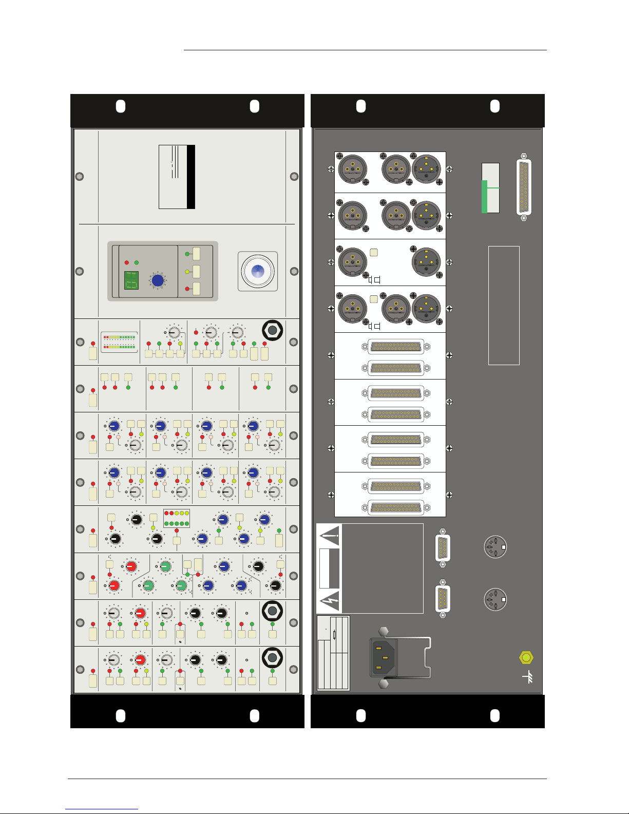
The Solid State Logic X-Rack unit has been developed from the successful range of XLogic outboard
equipment and provides a flexible solution to those engineers requiring a larger number of processing
units in a compact package.
The additional space provided by the X-Rack allows the processing modules to be vertically orientated,
providing a more familiar interface to users of Solid State Logic’s renowned range of mixing consoles, and
makes it possible to include Solid State Logic’s Total Recall system – the first time this has been available
on an analogue outboard unit.
1.1.1 This Manual
The object of this manual is to provide purchasers of the X-Rack unit with information in the following
areas:
• Operation of the unit
• Safety considerations
• Installation requirements
• Electrical connections and cabling
• Connector pin-outs
• Specifications and physical dimensions
This manual is applicable to X-Rack units from serial number XRK110 onwards and assumes that the X-Rack
unit is running V1.4/2 or later software. Please refer to Section 4 of this manual for instructions on how to
check the current software version and how to obtain and install a newer version if required.
1.2 Warranty
Pursuant to the Solid State Logic Terms and Conditions, under European consumer law the purchaser has
full statutory warranty rights for two years from the date of delivery of the product. The warranty is valid
only in those Member States of the European Union (EU) who have adopted the applicable EU law into
their national legislation, otherwise a warranty term of one year will apply. The applicable national
legislation governing the sale of consumer goods is not affected by this warranty. Warranty claims will
only be accepted if the purchased product has been used for its intended purpose. Any purchased product
used for an unintended purpose will not be eligible for warranty protection. For all warranty inquiries or
claims please address the claim to us if the purchase was directly from us or otherwise to the dealer from
which you purchased the product within a period of two months from the date on which you detected its
lack of conformity with the terms of the warranty. Please include your original proof of purchase when
initiating the claim.
1.2.1 Out of Warranty Repairs
In the event of a fault arising after the warranty period has expired the unit should be returned to Solid
State Logic either directly or via your local dealer. You will be charged for the time spent on the repair (at
Solid State Logic's current repair rate) plus the cost of parts and shipping. Note that no units can be
accepted for repair without prior arrangement (see below).
1.2.2 All Returns
• No unit will be accepted for repair by Solid State Logic unless accompanied by a valid RMA (Return
Material Authorisation) number, obtainable from Solid State Logic prior to shipping.
• All units should be shipped to Solid State Logic in suitable rigid packaging – Solid State Logic cannot
be held responsible for any damage caused by shipping units in other packaging. In such cases Solid
State Logic will return the unit in a suitable box, which you will be charged for.
• Please include all items – such as this manual, cables etc. – originally provided with unit.
Page 10

Page 2
X-Rack Owner’s Manual
2. Safety Considerations
This section contains definitions and warnings, and practical information to ensure a safe working environment.
Please take time to read this section before undertaking any installation work.
2.1 Definitions
‘Maintenance’
All maintenance must be carried out by fully trained personnel. Note: it is advisable to observe suitable ESD
precautions when maintenance to any part is undertaken.
‘Non-User Adjustments’
Adjustments or alterations to the equipment may affect the performance such that safety and/or international
compliance standards may no longer be met. Any such adjustments must therefore only be carried out by fully
trained personnel.
‘Users’
This equipment is designed for use solely by engineers and competent operators skilled in the use of professional
audio equipment.
‘Environment’
This product is a Class A product intended to form an integrated component part of a professional audio
recording, mixing, dubbing, film, TV, radio broadcast or similar studio wherein it will perform to specification
providing that it is installed according to professional practice.
2.3 Installation
Voltage Selection and Fusing
The X-Rack unit has an auto-sensing power supply that can operate on 100 – 230V without adjustment.
The X-Rack power supply module is internally fused. If the fuse should fail for any reason the unit should be
returned to Solid State Logic for repair/replacement as appropriate.
Safety Earth Connection
Any mains powered item of Solid State Logic equipment that is supplied with a 3-core mains lead (whether
connectorised or not) should always have the earth wire connected to the mains supply ground. This is the safety
earth and grounds the exposed metal parts of the racks and cases and should not be removed for any reason.
Note that the earth stud provided on the rear of the equipment is a functional earth not a safety earth.
2.2 Electrical Safety Warning
When installing or servicing any item of Solid State Logic equipment with power applied, when cover
and/or blank panels are removed, HAZARDOUS CONDITIONS CAN EXIST.
These hazards include: High voltages
High energy stored in capacitors
High currents available from DC power busses
Hot component surfaces
Any metal jewellery (watches, bracelets, neck-chains and rings) that could inadvertently come into contact
with uninsulated parts should always be removed before reaching inside powered equipment.
Page 11
Page 3
Safety Considerations
Mains Supply and Phases
To ensure safe operation of this equipment, connect only to an ac. power source that contains a protective
earthing (PE) conductor. This equipment is designed for connection to single phase supplies with the neutral
conductor at earth potential – category TN or TT – and is fitted with a protective fuse in the live conductor only.
This equipment is not designed for use with live and neutral connections reversed or where the neutral
conductor is not at earth potential (IT supplies). This equipment should not be connected to a power system that
switches open the return (neutral) lead when the return lead also functions as the protective earth (PE).
Mains cables will be coded with the following colour scheme:
LIVE: Brown
NEUTRAL: Blue
EARTH: Yellow/Green
Mains Isolation and Over-Current Protection
An external disconnect device is required for this equipment; a detachable power cord, as fitted to this
equipment, is a suitable disconnect device. Note that the socket outlet used for the detachable power cord should
be installed near the equipment and should be easily accessible.
An external over-current protection device is required to protect the wiring to this equipment which must be
installed according to current wiring regulations. The fusing or breaking-current is defined in the environmental
specification in Section 5.0 of this manual. In certain countries this function is supplied by use of a fused plug.
CE Certification
Note that the majority of cables supplied with Solid State Logic equipment are fitted with ferrite rings
at each end. This is to comply with current European CE regulations and these ferrites should not be
removed. If any of the equipment metalwork is modified in any way the CE certification status of the
product may be adversely affected.
Note that a frame or chassis terminal stud (functional earth) has been fitted to this equipment to provide a
convenient low impedance bonding point for interconnected equipment, should it be required.
FCC Notice
This equipment has been tested and found to comply with the limits for a Class A digital device, pursuant to part
15 of the FCC Rules. These limits are designed to provide reasonable protection against harmful interference
when the equipment is operated in a commercial environment. This equipment generates, uses, and can radiate
radio frequency energy and, if not installed and used in accordance with the instruction manual, may cause
harmful interference to radio communications. Operation of this equipment in a residential area is likely to cause
harmful interference in which case the user will be required to correct the interference at his own expense.
Instructions for Disposal of WEEE by Users in the European Union
The symbol shown here is on the product or on its packaging, which indicates that this product
must not be disposed of with other waste. Instead, it is the user’s responsibility to dispose of their
waste equipment by handing it over to a designated collection point for recycling of waste
electrical and electronic equipment. The separate collection and recycling of your waste
equipment at the time of disposal will help to conserve natural resources and ensure that it is
recycled in a manner that protects human health and the environment. For more information
about where you can drop off your waste equipment for recycling, please contact your local city office, your
household waste disposal service or where you purchased the product.
2.4 Graphical Symbols
The following symbols may be used either on the product or in this manual:
Protective Earth (ground).
Frame or Chassis terminal.
(Functional Earth)
General hazard – refer to user or service
manual for details.
Electrical hazard.
Page 12

Page 4
X-Rack Owner’s Manual
3. X-Rack Installation
3.1 Assembling the X-Rack
The X-Rack unit is normally shipped either as an empty rack (SSL Part No. 729935X1), a part filled (custom)
rack or as a fully loaded unit; for example, a unit fitted with eight 729618X1 Dynamics modules (SSL
Part No. 729935X2) – if you have purchased a fully loaded unit you should skip the rest of Section 3.1.
In the case of empty or part filled racks, any empty module slots will be covered by blank panels which
will need to be removed before fitting additional modules. Panels for module slots and the Total
Recall/CPU are secured, top and bottom, by a ‘one piece’ floating threaded bar. The position of the bar is
factory set so that there is adequate space to accommodate eight module panels. The correct position of the
threaded bars is initially set when the Total Recall/CPU module is installed and screwed in position
against the inside right edge of the rack.
Do not attempt to fit or remove modules with power applied. Always switch the rack off and remove the power
cord prior to working on this unit. When fitting or removing modules, it is advisable to observe suitable ESD
precautions. Take care when handling modules and blank panels; sharp corners may be present.
Modules are fitted from the front of the X-Rack, normally starting from the left hand end. Note that it is
recommended that any required blank panels (SSL Part No. 729618X2) are fitted prior to fitting modules.
Each module plugs into the backplane; use the two 8mm M3 counter sunk screws supplied with the
module or blank to fix the item to the front of the rack – a 2mm AF hex key is supplied with the X-Rack
unit. The rear connector panel or blank should be screwed to the rear of the case using the two 8mm M3
button head screws supplied with the module. The end result should be a unit that is fully loaded with
modules and/or blank panels. For ease of fitting, do not tighten the screws until all modules and/or blank
panels have been fitted.
To ensure peak operating performance, please ensure all front and rear panel fixing screws are securely
tightened; slight warping on the rear of the chassis may be observed – this is no cause for concern.
Generally, any module may be fitted in any position but with the following provisos:
• To use the Dynamics Link function, Dynamics modules must be placed in adjacent slots.
• The Dynamics Link function should only be used with similar types of Dynamics module!
• Only one Master module should be fitted in any one X-Rack.
• When fitting a Master module to X-Rack serial no. XRK0110 or earlier, the module should be fitted
immediately to the right of any modules which use either the Mix, Record or Solo/AFL Buses. This
limitation does not apply to later X-Rack units.
3.2 Mounting
The X-Rack unit is designed to be rack mounted or free standing. It is 4RU (178mm/7 inches) high. Its
depth is:
• 180 mm/7.2 inches
• 255 mm/10.2 inches including connectors
The unit does not require rack shelves. A 1RU space should normally be provided above the unit.
The unit is supplied fitted with both feet and rack ears. If the unit is to be rack mounted the feet should be
removed using the supplied 2.5 mm AF hex driver. The same driver can be used to remove the rack ears
if the unit is to be free standing.
Feet and rack ears are fixed using M4 x 8mm screws – do not replace them with longer screws as this may
damage the rack electronics.
Page 13
Page 5
3.3 Connection
3.3.1 Power Connection
The X-Rack unit has an auto-sensing power supply that can operate on 100 – 230V without adjustment.
The power connection is made via a standard IEC mains cord to an un-switched IEC mains socket on the
rear panel and a latching power switch is provided on the front panel of the unit.
3.3.2 Audio Connection
Generally, each module will have an input connector (normally a female XLR) and an output connector
(normally a male XLR). Depending upon the type of module other connectors, such as key inputs, may be
present also. Connect the module inputs to the insert sends of your console or to your workstation outputs.
Connect the module outputs to the corresponding insert returns or to your workstation inputs.
Once the unit is connected switch it on, then route a signal to each channel in turn and check that it is
returned to the correct input on your console or workstation.
Some module input and output gains can be set to operate at a nominal level of +4dBu or –10dBV using a
switch on the connector panel. Select the appropriate level for the equipment you are connecting to. If in
doubt either refer to the section of this manual specific to the particular module or experiment!
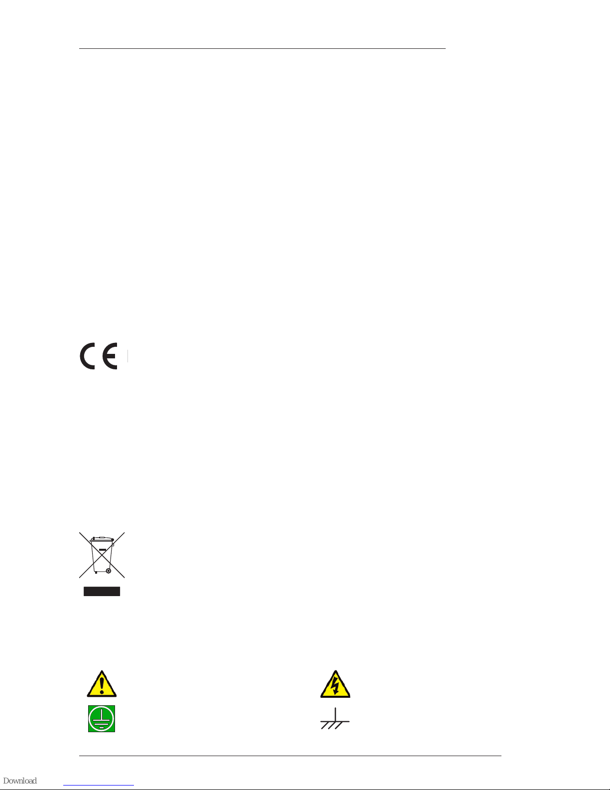
3.3.3 Connection to an AWS 900 or Matrix Console
If the X-Rack is being used with an AWS 900 or AWS 900+,
connect the TOTAL RECALL LINK IN connector (a 9 pin D-
type) to Serial Port 1 on the conole’s connector panel using the
supplied 2 metre cable. If connecting to a Matrix console,
connect the cable to the X-RACK/DIAG connector. For either
console, this cable may be extended to a maximum of 15 metres
using a suitable pin to pin extension cable.
If you have more than one X-Rack unit connect the
TOTAL RECALL LINK IN connector on the second unit to the
TOTAL RECALL LINK OUT connector on the first unit using
the supplied cable. Further units may be connected in the same
manner up to a maximum of four (AWS 900/900+) or six
(Matrix).
3.3.4 MIDI Connection
The MIDI port can be used for several functions:
• Archiving of the 32 internal stores as SysEx (System Exclusive) dumps
• Remote control of the ‘soft’ functions of the XR622 Master module
• Updating the system software
If you wish to use this facility connect the X-Rack MIDI IN connector to a spare MIDI out connector on
your MIDI interface and the X-Rack MIDI OUT connector to the corresponding MIDI input.
A separate connection is required for each X-Rack.
3.3.5 Mix Bus Link
Some X-Rack modules can route signals onto the X-Rack’s internal mix busses. This 25-way ‘D’ type
connector is provided to enable access to these buses and, using this connector, multiple X-Racks may be
connected together enabling a large stereo mix system to be constructed. The pinout for this connector is
detailed in Section 5.2.
TOTAL RECALL
LINK IN
MIDI IN
MIDI OUT
TOTAL RECALL
LINK OUT
X-Rack Installation and Operation
Page 14
Page 6
X-Rack Owner’s Manual
4. Operation – Total Recall
4.1 Overview
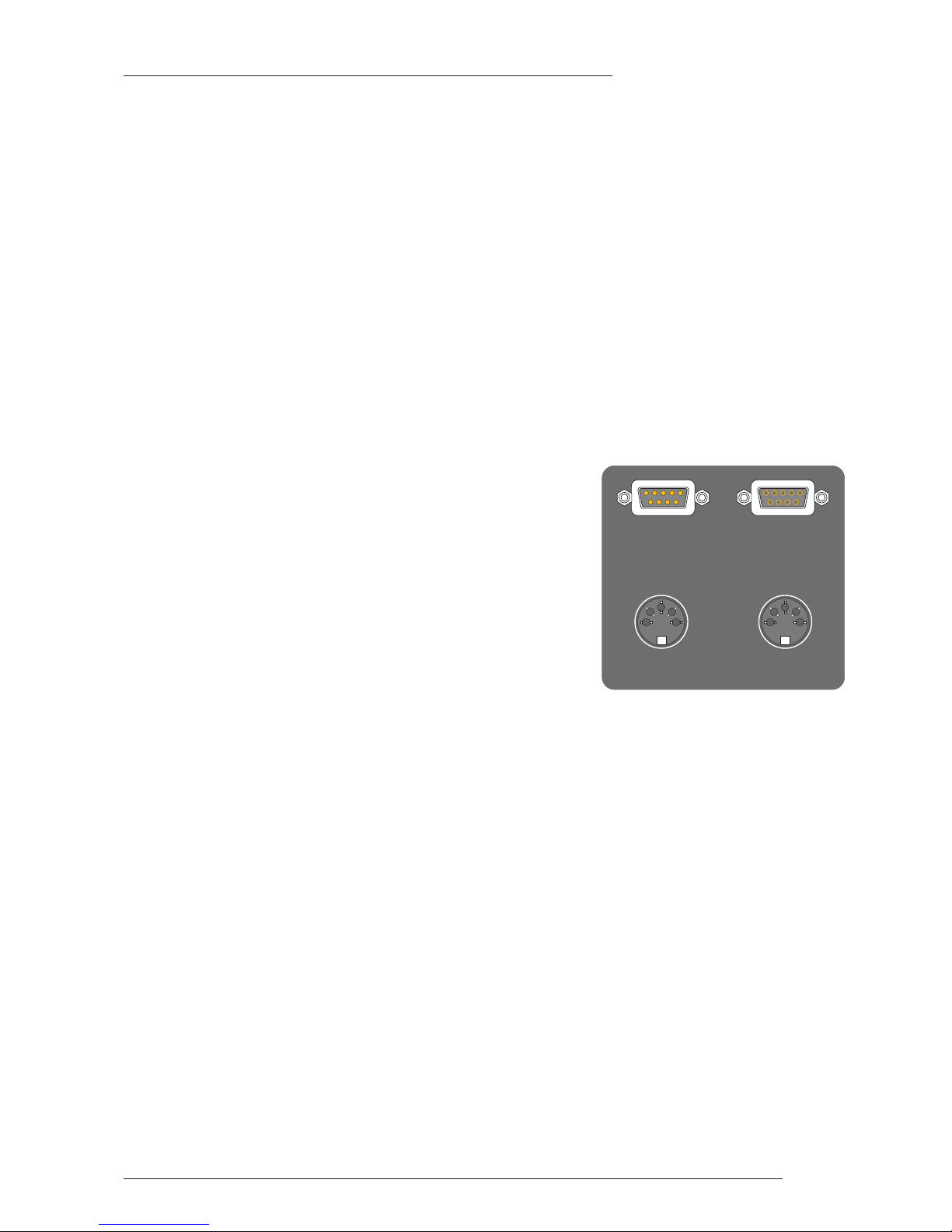
The Total Recall computer stores all of the switch and rotary control
positions for each X-Rack module in one of thirty two internal stores.
These can be recalled and compared with the current settings using
front panel LEDs to show which controls do not match. If the module
layout has changed since the snapshot was taken, only the modules
that match will be recalled.
The contents of all the stores can be archived and restored as a MIDI
system exclusive data dump.
Additionally, the X-Rack can interface with the Total Recall system on
AWS 900, AWS 900+ or Matrix consoles. This allows the settings of up
to four (AWS 900/900+) or six (Matrix) X-Rack units to be stored along
with the console settings.
4.2 Stand-alone Mode
4.2.1 Saving Stores to Internal Memory
A maximum of 32 stores can be saved in internal non-volatile memory, provided the stores have not been
write-protected – indicated by the ‘Wr Prot’ LED being illuminated.
First select a store by turning the D-Pot , then press SAVE to
store all of the current control positions.
If the store has already been used the SAVE LED will flash. Press the
SAVE switch a second time to overwrite the store.
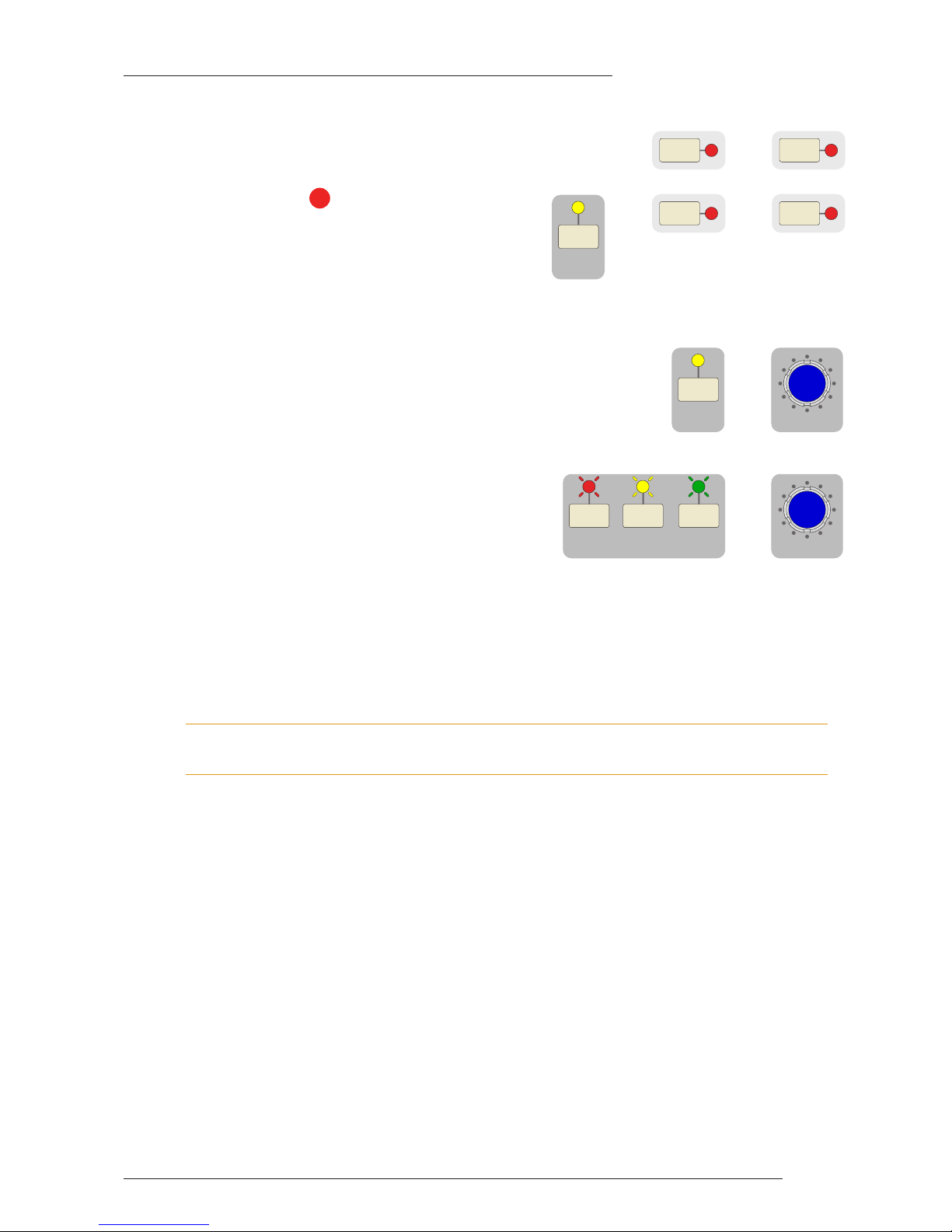
4.2.2 Recalling and Displaying Stores
To select a store using the D-Pot then press the D-Pot to select that store.
The current store is displayed on the dual 7-segment display .
If the selected store is empty the ‘Empty’ LED lights and the unit will not switch to display mode.
With a valid store selected, the X-Rack module SEL LEDs will light if the module type in the store (EQ,
Dynamics etc.) matches the module currently fitted in that slot. A flashing SEL LED indicates that some controls
on that module do not match the stored positions. A steady LED shows that all controls are matched. The
switch LEDs will light if the current switch position does not match the stored positions. Press or release
the switch as required to extinguish the LED.
Above each rotary control is a bi-colour LED:
The LED extinguishes when the control matches the stored position.
If a store is already being displayed when you select a different store the display will flash and the new
store will not become active until you press the D-Pot for a second time.
4.2.3 Exiting Display Mode
Push the D-Pot a second time to exit display mode.
All SEL LEDs will extinguish and the channel switch LEDs will now show the position of their respective
switches.
4
The LED lights red if
the control needs
turning anti-clockwise.
or
The LED lights green if
the control needs
turning clockwise.
2
1
4
5
4 5
P
ush to Select
SAVE
3
S
ETUP/
MIDI
S
AVE
Push to Select
C
OPY/
DEL
TOTAL RECALL
Empty
Wr Prot
1
2
3
4
5 6 7
Page 15
Page 7
X-Rack Installation and Operation
4.2.4 Copy/Swap
While displaying a TR setup pressing and holding a module SEL switch
and then pressing a second SEL switch will swap the setting of the two
channels.
Selecting COPY/DEL and then doing the same will
copy settings from the first channel to the second.
Note that Copy/Swap is only allowed between similar
modules; the unit will not allow you to swap settings
between an EQ module and a Dynamics module for
instance!
4.2.5 Deleting Stores
Stores can be cleared (to remove unwanted stores before a SysEx dump) by
holding down COPY/DEL till it’s LED flashes and pressing the D-Pot
switch (while still holding down the COPY/DEL switch). Additional stores
can be deleted by holding down the COPY/DEL switch, selecting the
second store with the D-Pot and pressing the D-Pot again.
4.2.6 Delete All
All stores can be cleared by holding down all three
switches until their LEDs flash, then pressing the D-Pot
switch.
4.3 Remote Mode
4.3.1 System Requirements
The X-Rack ‘TOTAL RECALL LINK IN’ connector must be connected to either AWS 900 serial port 1 or
the X-RACK/DIAG connector on Matrix using the pin-to-pin serial lead supplied with X-Rack – see
Section 3.3 for more details. If more than one X-Rack is connected each X-Rack must have a different
address – refer to the Setup/MIDI Mode Section.
The AWS 900 must be running V1.2/6 or higher software and have Total Recall enabled for this to function.
Current AWS 900 software can be downloaded from the SSL website.
4.3.2 Operation
Pressing the Total Recall STORE switch on the console will send a message to all attached X-Racks asking
for the current control settings to be returned. The returned settings are appended to the console’s Total
Recall stores and are automatically archived and restored as part of the console Total Recall system.
Similarly, displaying a Total Recall setup on the console will return the selected Total Recall setup to the XRack unit(s). The remote load command will always replace the current setup and the X-Rack display will
read ‘re’.
To display the new settings, press the D-Pot as in ‘Stand-alone’ mode and to exit display mode press the
D-Pot a second time. If the console store does not contain valid data (for example if it was saved on a
console not connected to an X-Rack) the ‘Empty’ LED will light and it will not be possible to select display
mode.
Settings can be saved to X-Rack’s local store and recalled at any time by turning the D-Pot (though see the
Remote option in the Setup menu section). Storing the Total Recall settings on the console will always save
the current state of the X-Rack and displaying a Total Recall setup will replace the store to be displayed
with the store from the console.
See the Remote and the Address options in the Setup/MIDI Mode Section.
SETUP/
MIDI
SAVE COPY/
DEL
+
Push to Select
C
OPY/
DEL
+
Push to Select
6
COPY/
DEL
&
SEL+SEL
SEL
+
SEL
Page 16

Page 8
X-Rack Owner’s Manual
4.4 Setup/MIDI Mode
4.4.1 Overview
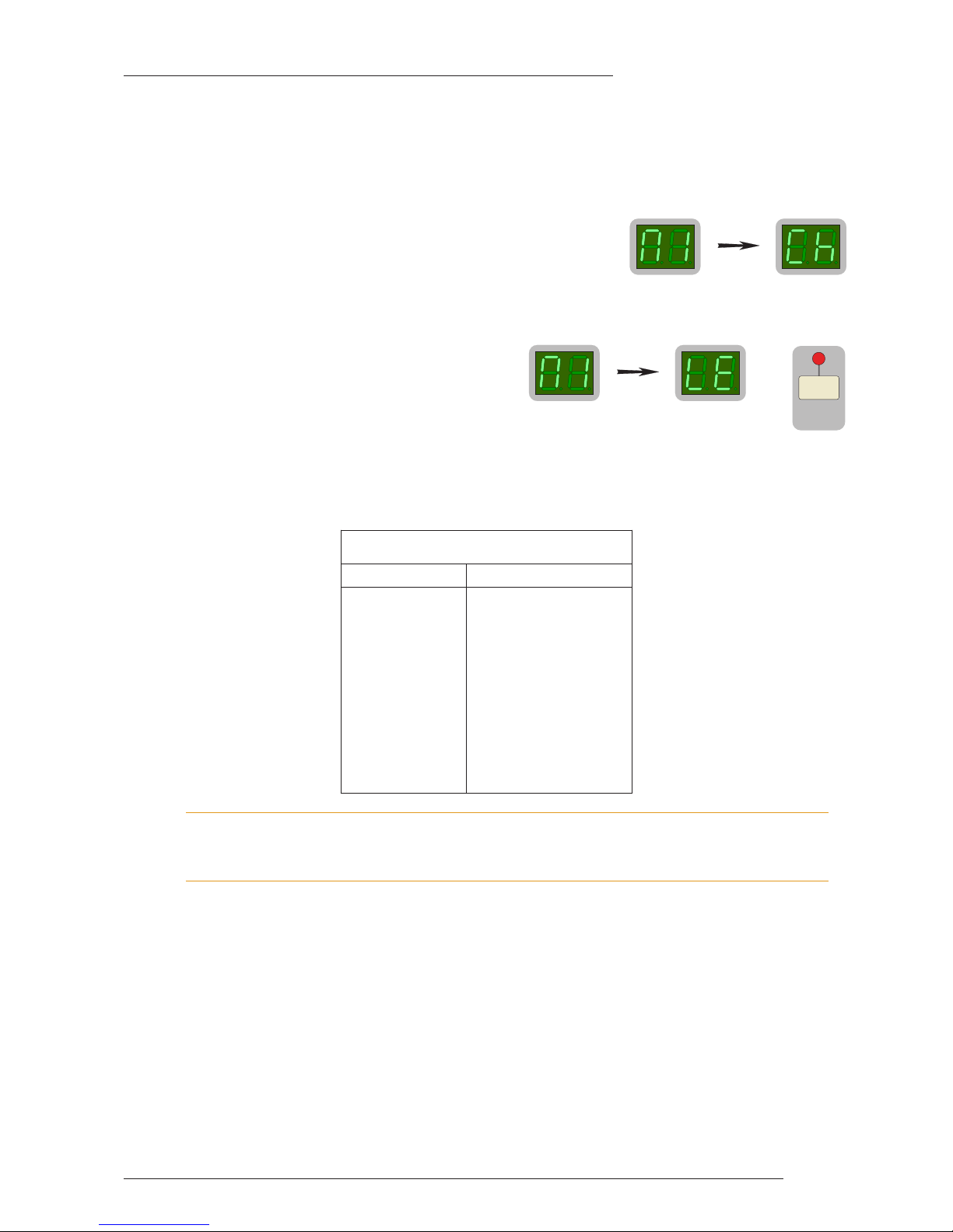
Enter SETUP/MIDI mode by holding down SETUP/MIDI until the
display reads ‘5e’. The SETUP/MIDI LED flashes to show you are in
this mode. Press and hold the same switch to return to normal
operation.
Navigating in the Setup menu
The setup menu contains a number of options. These each contain a number of sub-options. Turn the
D-Pot to scroll through the main list of options and push the D-Pot to select an option for editing. The DPot will now scroll through the available list of possible settings for that option. Pressing the D-Pot again
will save the currently selected setting and return to the normal option menu. The options are:
Option Display Setting Notes
Enter Setup 5e None
MIDI m1 MIDI Channel (ck) Select the MIDI channel to listen to for
remote control of the XR622 Master
module (01 to 16 or al for all)
MIDI Learn (le) Define which MIDI controls operate
the XR622 Monitor module controls
Save (sa) and Load (l0) Send or receive SysEx data to save or
load all internal stores to a MIDI
sequencer or librarian
Write Protect pr Off (0f) and On (0n) Toggles write protect on and off
Remote re Off (0f), On (0n) or MIDI (m1) Toggles remote Total Recall mode on
and off or enables MIDI remote control
of the XR622 Monitor module controls
Set Address ad a1, a2, a3, a4 Sets X-Rack address for AWS Total
Recall interface
Record/Mix rm Sum (su) or Alternate (al) Record/Mix mode setting for the
XR623 Line Return module.
Show Version ve Displays software version
Test te Test LEDs (tl) All module LEDs flash
Test switches (t5) Press TR computer switches to light
corresponding LEDs
Test pots (tp) Shows position of pots
Update Software fl Program upgrade mode (te) The only exit from this mode, without
updating the X-Rack software, is to
power-cycle the unit.
Dim Level d1 –3 (03) to –30 (30) dB Sets the ‘DIM’ level for the XR622
Monitor module
7
S
ETUP/
MIDI
Page 17
Page 9
X-Rack Installation and Operation
4.4.2 MIDI (m1)
Under this menu it is possible to set the MIDI controls which can control parts of the X-Rack XR622 Master
module and also to save and load all internal stores to and from a MIDI sequencer or librarian as a SysEx
dump.
MIDI Remote Channel (ck)
Under the MIDI menu, use the D-Pot to select MIDI Channel.
Then press the D-Pot and turn it to select the required channel (‘01’
to ‘16’ or ‘al’ for all/any channel). This is the MIDI channel that will
be used for remote control of the XR622 Master module.
By default X-Rack will listen on all channels.
MIDI Remote Learn (le)
Under the MIDI menu, use the D-Pot to select
MIDI Learn (le) and press SAVE. The green
‘Wr Prot’ LED will flash to indicate you are in MIDI
Learn mode. Operating any one of the ‘soft’ controls
on the XR622 Master module will cause the LED of
the selected control to flash (the module ‘SEL’ LED
will flash if either of the potentiomenters have been chosen) – indicating it has been chosen. Assign a MIDI
controller to the selected function by operating the required MIDI controller. To cancel or change the
assignment either operate the Master module control again, or operate a different control. A successful
assignment will be indicated by the flashing LED changing to just being illuminated steadily.
Only single controls can be mapped to a MIDI controller. Therefore, mapping an X-Rack control to a MIDI
controller which is already in use will remove the previous mapping. The original X-Rack control will require
re-mapping itself before it can be controlled again.
To exit MIDI Learn mode, press the D-Pot – the green ‘Wr Prot’ LED will stop flashing. Switch assignments
can be reset to the system defaults by pressing COPY/DEL when in MIDI Remote Learn mode; the ‘Empty’
LED indicating when the assignments have been deleted.
MIDI Save and Load
In order to use the MIDI save and load utility the X-Rack must be connected to a computer running a
suitable sequencer or MIDI librarian package.
All the stored setups can be saved as a System Exclusive dump to any software package that supports
MIDI SysEx dumps. In practice this includes most packages and you would normally save the TR setups
to an additional track in your current DAW project so that your setups are stored with the rest of the
project.
Default MIDI Controller Mapping
MIDI Controller Master Module Control
1 MIX
2 REC
3 EXT
4 ALT
5 MONO
6 DIM
7 CUT
8 AFL Level
9 Monitor LEVEL
+
SAVE
Page 18
Page 10
X-Rack Owner’s Manual
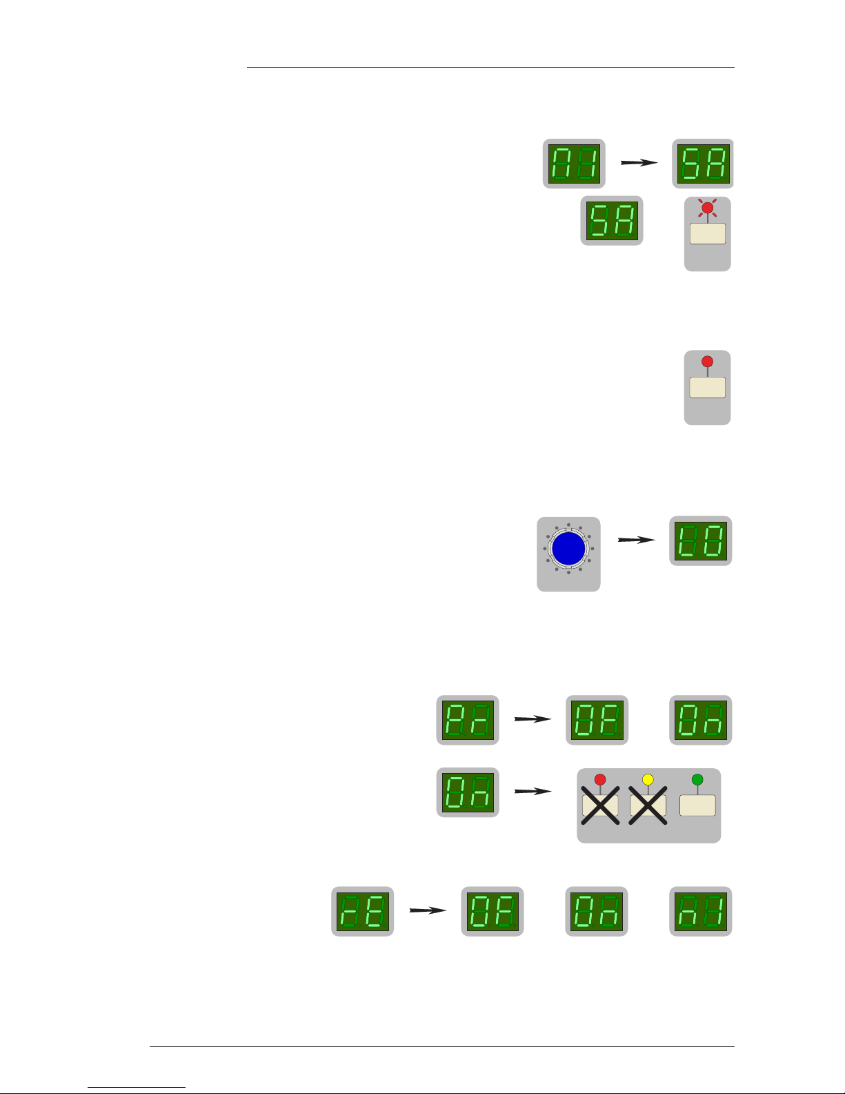
Saving Setups to a Mac or PC (sa)
With the X-Rack in Setup Mode, saving TR setups to Mac or PC can be achieved as follows:
• Under the MIDI menu, use the D-Pot to select MIDI Save.
• The display will show ‘5a’ and both the ‘SAVE’ LED and display flash.
• Create an additional MIDI track in your DAW program. Select its input and output to be the MIDI
port connected to your X-Rack.
• If available select the track to store System Exclusive data and record enable the MIDI track.
• Press Play and Record on the DAW to put the MIDI track into record.
• Press the SAVE switch to start transmission of all saved Total Recall setups.
A ‘rotatingsegment’ display will start and run until all data has been transmitted
• Once the display changes to ‘m1’ stop the DAW to end recording.
An unlimited number of Total Recall setups can be stored in this way.
Loading Setups from a Mac or PC (l0)
Restoring setups from a Mac or PC is even simpler:
• Enter MIDI mode as before, and turn the D-Pot until the display
changes to ‘l0’ and begins to flash.
• Locate the DAW to just before the SysEx data containing the setups you wish to load.
• Play through the SysEx block of data. The display will show a rotating segment while data is received.
As soon as the X-Rack detects the start of valid data it will delete all the current setups and replace
them with the stored ones from the MIDI track.
4.4.3 Write Protect Mode (pr)
Write Protect prevents existing stores being over
written or deleted, providing an extra level of
protection for units that have been programmed
with particular settings.
When set to ‘0n’ the Save and Delete functions are
disabled. When set to ‘0f’ they are enabled. The
‘Wr Prot’ LED lights to show this mode has been
selected.
4.4.4 Remote Mode (re)
This mode enables remote
control of X-Rack, either from a
console for saving and recalling
Total Recall snapshots or from a
MIDI controller for control of the XR622 Master module.
When Remote Mode is ‘0n’, selecting a TR setup on the console will change the current X-Rack setup to
the one saved in the console. The X-Rack display will change to read ‘re’ (remote) and pressing the D-Pot
will display the TR setup as normal. When Remote Mode is ‘0f’, turning the D-Pot will change the current
or or
SETUP/
MIDI
SAVE COPY/
DEL
or
P
ush to Select
S
AVE
&
S
AVE
Page 19
Page 11
X-Rack Installation and Operation
X-Rack setup to one of the internal stores but when Remote Mode is set to ‘0n’ the D-Pot is disabled once
the X-Rack has received a setup from the console. This also prevents saving or deleting of local stores.
When Remote Mode is set to MIDI (‘m1’), the ‘soft’ controls on the XR622 Master module may be remotely
operated as MIDI controls. The Master module controls will continue to function until a valid MIDI packet
has been received, after which all of the ‘soft’ controls will be locked out – this condition will be indicated
by illumination of the right-hand decimal point in the X-Rack display. Which MIDI channels and controls
are used is set through the MIDI learn process (see above).
Setting Remote Mode to MIDI will disable the console Total Recall connection.
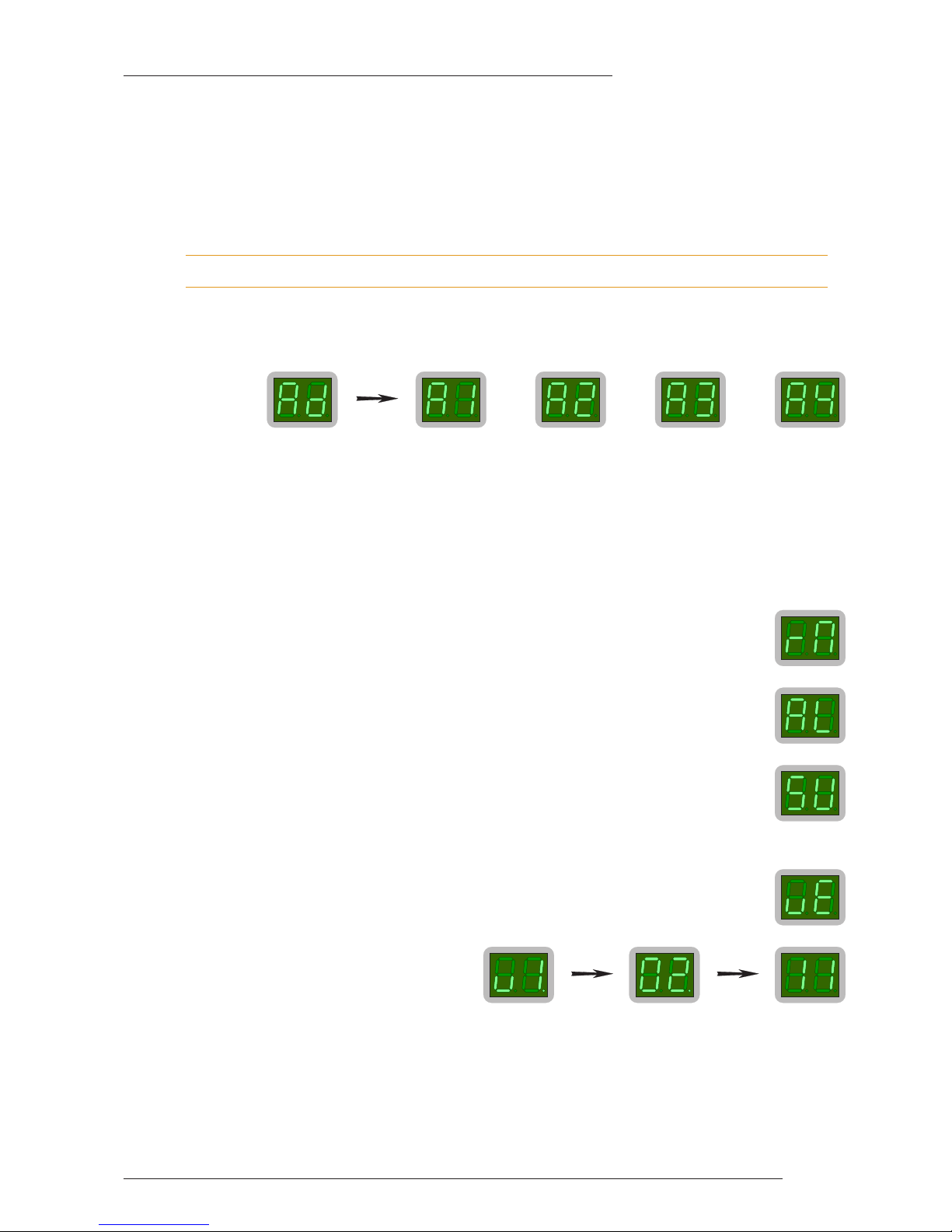
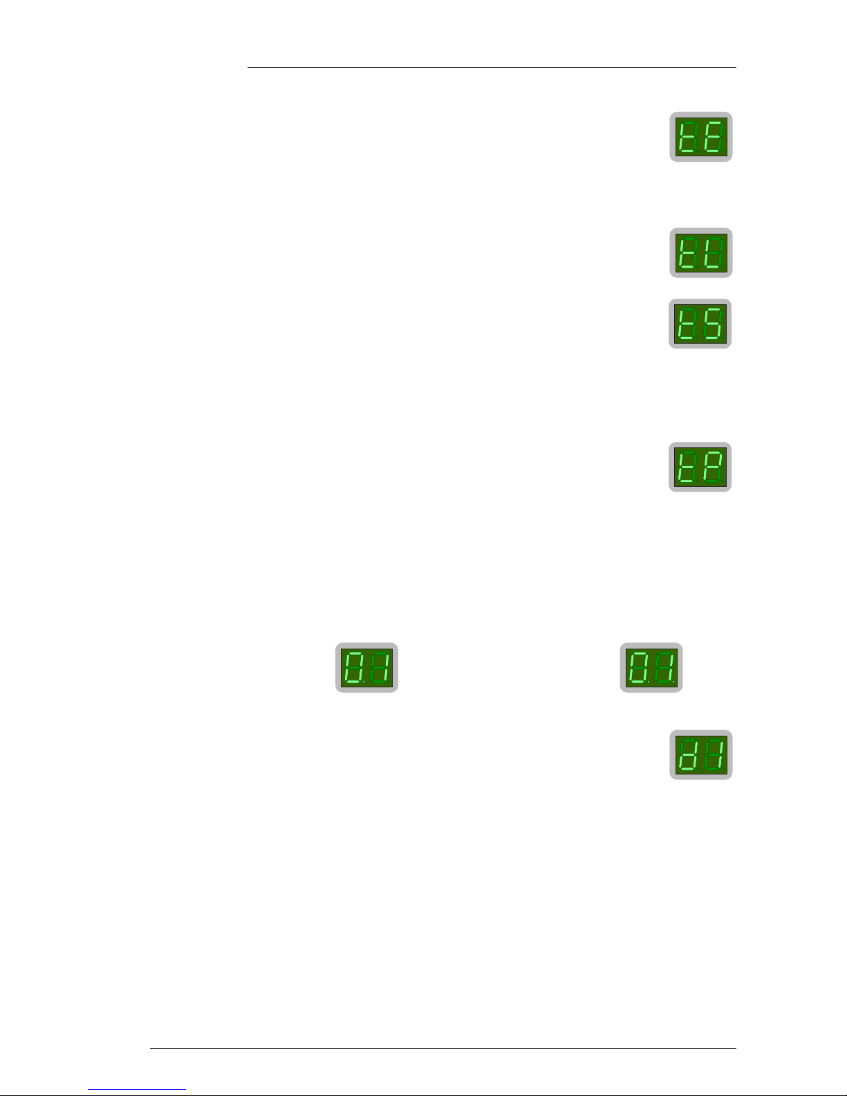
4.4.5 Address Setting (ad)
If more than one X-Rack is to be connected to an AWS 900 then each must have a different address. Enter
Address mode and turn the D-Pot so the display reads ‘a1’, ‘a2’, ‘a3’ or ‘a4’ then press the D-Pot to save
the address:
The order of addressing is not important, but we recommend you address the racks in the order they are
connected to the AWS 900. This will increase the chances of data being correctly mapped if you move to a
different facility.
4.4.6 Record/Mix (rm)
This function is applicable only to X-Rack units fitted with one or more XR623 Line Return module(s). The
‘rm’ setting allows the REC switches on these modules to opperate in either ‘Alternate’ mode where the
switches flip between the Record and Mix busses or ‘Sum’ mode where the Mix bus is permanently fed
with signal routed to the Record bus only when the REC switch is pressed.
Select Record/Mix by turning the D-Pot till the display shows ‘rm’.
To select ‘Alternate’, turn the D-Pot to show ‘al’ then press the D-Pot to set it.
To select ‘Sum’, turn the D-Pot to show ‘su’ then press the D-Pot to set it.
4.4.7 Show Version (ve)
Select Show Version by turning the D-Pot till the display shows ‘ve’.
Press the D-Pot to show the software version
in three blocks. As an example, software
version ‘V1.3/1’ will display in this sequence
before returning to display ‘ve’.
or or or
Page 20
4.4.8 Test Mode (te)
This mode is used for testing the front panel switches and LEDs.
There are three test modes available, selected using the D-Pot as for the other Setup functions:
Test LEDs (tl)
This toggles the bi-colour LEDs above the pots between red and green.
Test Switches (t5)
This mode flashes all the channel switch LEDs. Pressing any switch (apart from SEL)
should make the corresponding LED flash out of time with the other LEDs on the front
panel.
Pressing a SEL switch should light the corresponding LED.
Pressing any of the switches on the TR computer section should flash the corresponding LED. Pressing the
D-Pot should turn off the flashing ‘Empty’ LED and flash the ‘Wr Prot’ LED.
Test Pots (tp)
This mode scans all the modules from the top left to the bottom right of the unit and
displays the value of the last rotary control not turned fully counter clockwise. If all
controls are turned counter clockwise then the display shows ‘tp’.
To use this diagnostic first turn all controls fully counter clockwise. The module SEL LEDs will flash on
all modules with a control not in the correct position and the individual pot LEDs will light green on all
controls not in the correct position. Turning any control should make the display change from ’02’ to ‘255’.
Note that ‘02’ is the lowest value that can be read before the pot is skipped.
The decimal points on the two displays are used to show numbers greater than ‘99’. The left hand decimal
point lights to indicate that you should add a 100 to the displayed value and both decimal points light to
show that you should add 200 to the displayed value, hence:
4.4.9 Set DIM Level (d1)
Select DIM Level by turning the D-Pot till the display shows ‘d1’.
Press the D-Pot to show the current DIM level. The level can be varied from –3dB (‘03’) to –30dB (‘30’).
Press the D-Pot once more to change the DIM level.
‘101’ will display like this: whilst ‘201’ will display like this:
Page 12
X-Rack Owner’s Manual
Page 21
Page 13
X-Rack Installation and Operation
4.5 Software Download and Installation
Software to upgrade your X-Rack unit should be downloaded from the SSL website (www.solid-state-
logic.com/support/utilities.html).
The X-Rack software is packaged as a 50kB (approximately) java archive, the format of which is
compatible with both PC and Macintosh (PowerPC and Intel but OS X only) platforms. Some users may need
to install additional files on their computer before continuing – see System Requirements below.
4.5.1 System Requirements
PC users should ensure that they have the latest version of Java installed. This can be downloaded from
www.java.com
. There is a link to this address on the download page.
To enable Java to access external MIDI devices, Mac OS X users may need to download and install either
‘Plumstone’ (PowerPC) or ‘MandolaneMIDI’ (Intel) from www.mandolane.co.uk
. Drag this file into the
‘
/Library/Java/Extensions
’ folder then restart the Macintosh before running the upgrade utility.
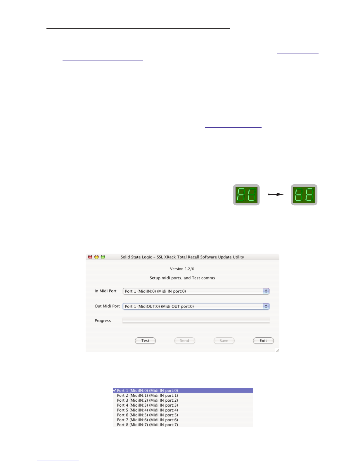
4.5.2 Software Update
Once the software package has been downloaded, it will need to be moved onto a Mac or PC that is
connected to the X-Rack via MIDI after which you will be ready to install the new software. The following
steps detail this process:
1. Ensure that the X-Rack is turned on and connected to a MIDI port on your PC/Mac.
2. Enter Setup mode and turn the D-Pot until the display shows
‘fl’ (‘Flash’). Press the D-Pot and the display should change to
read ‘te’ (‘Test’).
To exit from this mode without updating software turn the unit off and on.
3. Close all current applications on your PC/Mac.
4. If upgrading from V1.0/0 or V1.1/0 double click on the
xrack_flash.jar
file. If upgrading from V1.2/0 or
later, double click on the
xrack_vn_n_n.jar
file (where ‘
n_n_n
’ denotes the new version number). You
should see the SSL X-Rack Software Update Utility window appear:
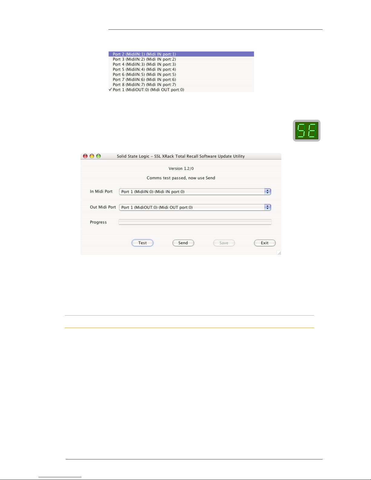
5. Go to the In MIDI Port menu. Select the MIDI IN port which is connected to your X-Rack from the drop
down list. In the example shown below this was ‘port 1’ on an 8-Port interface. If nothing appears in the
list check that you have installed the files listed in the System Requirements section opposite.
Page 22
Page 14
X-Rack Owner’s Manual
6. Go to the Out MIDI Port menu. Select the MIDI OUT port which is connected to your X-Rack:
Note that a PowerPC Macintosh (ie. using Plumstone Server) will show all MIDI Inputs at the top of the
list, MIDI Outputs at the bottom. You must scroll to the middle of the list to see the MIDI Out ports.
7. Click on the Test button. This transmits a packet of data to the X-Rack which should return
an acknowledgment to the computer. If the test was successful the message ‘Comms test
passed, now use send’ will be displayed and the display on the X-Rack should change to
read ‘se’.
If the test fails check that the correct MIDI port has been selected and that the X-Rack is in software
download mode, then repeat the test.
8. Once you have established a valid connection click on the Send button. The new code will now be
transferred to memory on the X-Rack. This process will take approximately 20 seconds. A progress bar and
transfer counter will be displayed on screen to enable you to observe the transfer progress and the X-Rack
displays will show a rotating segment.
During this time it is important that power to the X-Rack is not interrupted.
9. Once the software has been saved the X-Rack will re-boot. If you ran the ‘real’ X-Rack updater (a file
named
xrack_vn_n_n.jar
where ‘
n_n_n
’ relates to the software version) go to step 10. If however you ran
the
xrack_flash.jar
updater, the X-Rack will automatically switch to programming mode ready to accept
the real X-Rack software. Double click on the
xrack_vn_n_n.jar
file and repeat steps 5 through 8.
10. Once the new software has been saved a message will appear ‘Software update completed’ and the XRack will re-boot using the new software. Click on ‘Exit’ to close the Update Utility.
Page 23

Page 15
X-Rack Installation and Operation
5. Miscellaneous
5.1 X-Rack Internal Links and Fuses
5.1.1 Fuses (Mains Inlet)
The power supply module is internally fused. In the event of this fuse failing the entire unit should be
returned to your nearest SSL Service agent.
5.1.2 Internal Fuses
The internal power rail fuses will automatically reset once a fault condition has been removed and should
not need to be replaced.
5.1.3 Links
There are no user settable links.
5.2 X-Rack Connector Details
MIDI In
Location: Rear Panel
Conn’ Type: 5-pin DIN Female
Pin Description
1 n/c
2 0V
3 n/c
4 Signal +ve
5 Signal –ve
MIDI Out
Location: Rear Panel
Conn’ Type: 5-pin DIN Female
Pin Description
1 n/c
2 n/c
3 n/c
4 Signal +ve
5 Signal –ve
Total Recall Link In
Location: Rear Panel
Conn’ Type: 9-pin 'D' Type Male
Pin Description
1 Carrier (linked to 0V)
2 Rx
3 Tx
4 DTR (linked to DSR)
5 0V
6 DSR (linked to DTR)
7 RTS (linked to CTS)
8 CTS (linked to RTS)
9 RI (linked to 0V)
Total Recall Link Out
Location: Rear Panel
Conn’ Type: 9-pin 'D' Type Female
Pin Description
1 Carrier (linked to 0V)
2 Tx
3 Rx
4 DTR (linked to DSR)
5 0V
6 DSR (linked to DTR)
7 RTS (linked to CTS)
8 CTS (linked to RTS)
9 RI (linked to 0V)
Please note that the ‘D’ type connector binding posts fitted to the X-Rack chassis are all 4-40 UNC thread.
Page 24

Page 16
X-Rack Owner’s Manual
5.2 X-Rack Connector Details (cont.)
Mix Bus Link
Location: Rear Panel
Conn’ Type: 25-pin ‘D’ Type Female
Pin Description
1 Chassis
14 AFL/Solo Bus Left (–ve)
2 AFL/Solo Bus Left (+ve)
15 Chassis
3 AFL/Solo Bus Right (–ve)
16 AFL/Solo Bus Right (+ve)
4 Chassis
17 Mix Bus Left (–ve)
5 Mix Bus Left (+ve)
18 Chassis
6 Mix Bus Right (–ve)
19 Mix Bus Right (+ve)
7 Chassis
20 Record Bus Left (–ve)
8 Record Bus Left (+ve)
21 Chassis
9 Record Bus Right (–ve)
22 Record Bus Right (+ve)
10 Chassis
23 AFL/Solo Enable
11 n/c
24 n/c
12 n/c
25 n/c
13 n/c
Please note that the ‘D’ type connector binding posts fitted to the X-Rack chassis are all 4-40 UNC thread.
Page 25

Page 17
X-Rack Installation and Operation
5.3 Physical Specification
Depth: 180mm / 7.2 inches excluding front panel knob(s) and connectors
255mm / 10.2 inches including connectors, excluding front panel knob(s)
Height: 178mm / 7 inches (4 RU) excluding feet
Width: 440mm / 17.4 inches excluding rack ears
483mm / 19 inches including rack ears
Weight: 2.8kg / 6.2 pounds without modules fitted
3.5kg / 7.7 pounds with blank panels fitted
5.0kg / 11 pounds with modules fitted
Power: 50 Watts / 60VA with 8 modules fitted
Boxed size: 540mm x 300mm x 270mm / 21.25" x 12" x 10.63"
Boxed weight: 4.3kg / 9.5 pounds without modules fitted
5.0kg / 11 pounds with blank panels fitted
6.5kg / 14.3 pounds with modules fitted
* All values are approximate
5.4 Environmental Specification
Temperature Operating: 5 to 30 Deg. C
Non-operating: –20 to 50 Deg. C
Max. gradient: 15 Deg. C/Hour
Relative Humidity Operating: 20 to 80 %
Non-operating: 5 to 90 %
Max. wet bulb: 29 Deg. C (non-condensing)
Vibration Operating: < 0.2 G (3 - 100Hz)
Non-operating, power off: < 0.4 G (3 - 100Hz)
Shock Operating: < 2 G (10mSec. Max.)
Non-operating: < 10 G (10mSec. Max.)
Altitude Operating: 0 to 3000m (above sea level)
Non-operating: 0 to 12000m
Page 26

Page 18
X-Rack Owner’s Manual
Page 27
Page A-1
X-Rack Mic Amp Module
A. Mic Amp Module
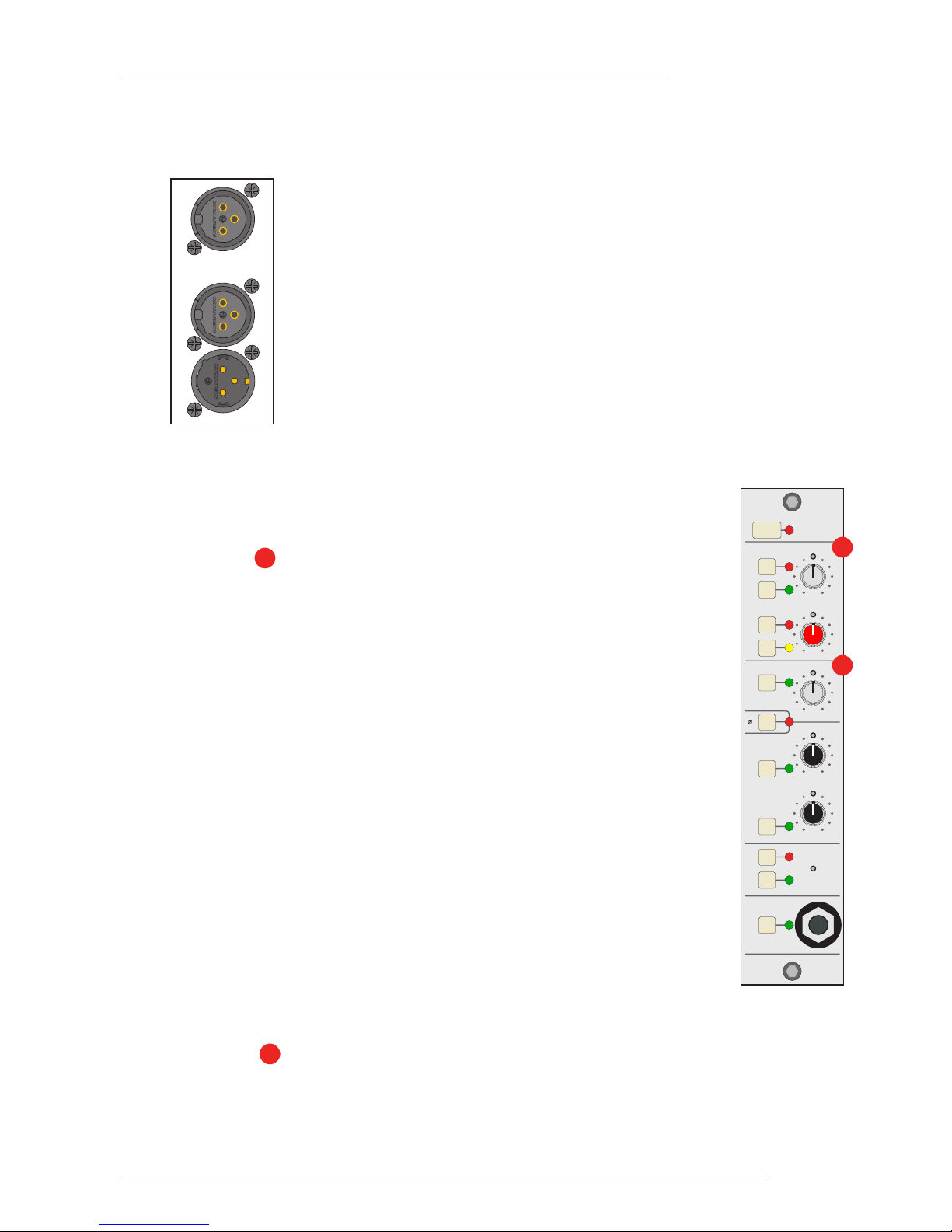
A.1 Connection
The rear panel of the module carries the Mic (‘IN’) and Line input (‘LINE’) XLRs along
with a single output (‘OUT’) XLR. The Line input and output operate at a nominal
level of +4dBu although the gain of the Line input can be varied by a front panel
control. Also contained on the front panel is an additional mono Jack socket for a high
impedance Instrument input.
A.2 Operation
The X-Rack Mic module contains three seperate input amplifiers; a Microphone
amplifier, an Instrument input and a Line input, any one of which may be selected
at any one time. A set of High and Low Pass filters are also provided.
A.2.1 MIC Section
Normally, the Microphone input on the rear of the module will be selected (‘LINE’
and ‘INST’ switches released); pressing the ‘INST’ switch selects the mono jack
instrument input on the front of the module. This is a very high impedance
unbalanced input intended to be used with guitar pickups etc. To help alleviate
‘hum’, a ground lift (‘GND LFT’) switch has been provided which places a 1k2Ω
impedance in series with the sleeve of this connector and audio ground in the
module. The gain of these inputs is continuously variable between +12dB and
+75dB.
The impedance of the Microphone input can be varied between ≈1k2Ω and ≈10kΩ
by selecting the ‘IMP IN’ switch and adjusting the ‘Z’ control. This allows the
connection of line level signals to the Microphone input if required, and provides an
alternative input impedance for some dynamic microphones.
The ‘PAD’ switch reduces the signal level of both the Microphone or Instrument
inputs by 20dB. Phantom power, for microphones requiring this, can be switched on
using the ‘+48V’ switch. Please note that X-Rack units prior to serial number XRK0110
are not normally enabled for +48V. However, a field retrofit kit (629620XR) is available for
these units. Any in-warranty X-Rack units can be upgraded free-of-charge; for units out of
warranty a charge will be made. Please contact your local distributor to order this kit, if
required.
Note. Please note that connecting a microphone to the X-Rack Mic module with phantom power
switched on is not advised as it may cause damage to either the microphone or the input
stage of the X-Rack module. Take care not to connect line level sources (keyboards etc.) to the
microphone input with phantom power switched on as this may damage the output stage of
the connected unit.
A.2.2 LINE Section
The Line input on the rear of the module is selected by pressing the ‘LINE’ switch. The gain of this input
can be varied by ±20dB from the nominal 0dB.
The Ø (Phase) switch reverses the phase of the selected input.
2
1
SEL
X
R621
MIC
INST
I
MP
+48V
PAD
LINE
LINE
H
F
I
N
IN
I
N
REC
REC
L
R
GND
LIFT
INSTRUMENT
OUTPUT
SIGNAL
LF
Z
LO HI
d
B
+75 +12
+20 -20
d
B
KHz
9 6
3
50
30 4
30 600
60
160 300
I
N
OUT
L
INE
1
2
Page 28

Page A-2
X-Rack Owner’s Manual
A.2.3 HF/LF Section
This section contains simple high and low pass filters as follows:
HF (Low Pass): Frequency range 50kHz – 3kHz (–3dB point)
Slope: 12dB/Octave
LF (High Pass): Frequency range 30Hz – 600Hz (–3dB point)
Slope: 18dB/Octave
The two filters can be switched into circuit independently.
A.2.4 OUTPUT Section
This small section contains a tri-colour signal present indicator and two routing
switches (‘REC L’ and ‘REC R’) which route the module signal onto a common
internal record bus.
The signal present indicator measures signals immediately prior to the output
amplifier. It will light GREEN for output signals above the lower threshold of
–60dBu, AMBER for signals between +4dBu and +24dBu and lights RED for signals
above +24dBu.
The record bus is used by the X-Rack XR622 Master Module which provides stereo
mix and monitor facilities, providing a compact solution for mixing and monitoring
in the analogue domain.
4
3
SEL
XR621
M
IC
INST
IMP
+48V
PAD
LINE
LINE
HF
IN
IN
I
N
REC
REC
L
R
GND
L
IFT
INSTRUMENT
O
UTPUT
S
IGNAL
LF
Z
LO HI
dB
+75 +12
+20 -20
dB
KHz
9 6
350
30 4
30 600
60
160 300
3
4
Page 29

Page A-3
X-Rack Mic Amp Module
A.3 Performance Specification
The following pages contain audio performance specification figures for the X-Rack Mic Amp module. No
other Solid State Logic products are covered by this document and the performance of other Solid State
Logic products can not be inferred from the data contained herein.
A.3.1 Measurement Conditions
For each set of figures on the following pages, the specific unit and test setup will be stated at the
beginning of that section. Any changes to the specified setup for any particular figure(s) will be detailed
beside the figures to which that difference applies.
A.3.2 Measurement References
Unless otherwise specified the references used in this specification are as follows:
• Reference frequency: 1kHz
• Reference level: 0dBu, where 0dBu ≈ 0.775V into any load
• Source impedance of Test Set: 50Ω
• Input impedance of Test Set: 100kΩ
• All unweighted measurements are specified as 22Hz to 22kHz band limited RMS and are expressed in
units of dBu
• All distortion measurements are specified with a 36dB/Octave low pass filter at 80kHz and are
expressed as a percentage
• The onset of clipping (for headroom measurements) should be taken as 1% THD
• Unless otherwise quoted all figures have a tolerance of ±0.5dB or 5%
• All measurements are made with the operating level switch set for +4dBu
A.3.3 Microphone Amplifier Performance
Signal applied to Microphone Input and measured at Output. Pad switched out and Input Gain control
set to +12dB (minimum).
Gain Continously variable from +12dB to +75dB
Independently switchable 20dB Pad available
Input Impedance Continously variable from ≈1k2Ω to ≈10kΩ
Output Headroom > +26dBu at onset of clipping
THD + Noise < 0.003% at 1kHz
(-18dBu applied, +28dB gain) < 0.006% at 10kHz
Frequency Response +0.05dB/-0.1dB from 20Hz to 20kHz
–3dB at 150kHz
Equivalent Input Noise < –127dB at maximum gain
(input terminated with 150Ω) < –90dB at 0dB gain (+20dB with Pad ‘IN’)
Common Mode Rejection > 75dB from 50Hz to 1kHz
(-10dBu applied, +30dB gain) > 70dB at 10kHz
Page 30

Page A-4
X-Rack Owner’s Manual
A.3.4 Instrument Input Performance
Un-balanced signal applied to Instrument Input and measured at Output. Pad switched out and Input
Gain control set to +12dB (minimum).
Gain Continously variable from +12dB to +75dB
Independently switchable 18dB Pad available
Input Impedance 1MΩ
Output Headroom > +26dBu at onset of clipping
THD + Noise < 0.03% at 1kHz
(-18dBu applied, +28dB gain) < 0.05% at 10kHz
Frequency Response +0.05dB/-0.1dB from 20Hz to 20kHz
–3dB at 150kHz
Equivalent Input Noise < –82dB at +12dB (minimum) gain
(Input terminated with 150Ω) < –88dB at +28dB gain (mid’ position)
A.3.5 Line Input Performance
Signal applied to Line Input and measured at Output. Input Gain control set to 0dB (indent).
Gain Continuously variable from –20dB to +20dB
Input Impedance > 10kΩ
THD + Noise < 0.005% from 20Hz to 20kHz
(+24dBu applied, 0dB gain)
Frequency Response ±0.1dB from 20Hz to 20kHz
–3dB at 150kHz
Equivalent Input Noise < –90dB
(Input terminated with 150Ω)
Page 31

Page A-5
X-Rack Mic Amp Module
A.4 Calibration Information
The X-Rack Mic Amp module is factory calibrated and should only need calibration if a potentiometer or
other component has been replaced or if it is suspected that there is a problem with calibration.
In each of the following instructions it is assumed that the lid of the X-Rack has been removed and that
power has been applied. It is also assumed that unless otherwise specified, all switches are released and
all front panel potentiometers are at unity or minimum position as appropriate. The required accuracy for
each adjustment will be specified along with the target value. All level and distortion measurements
should be made with audio-band 20Hz to 20kHz filters unless otherwise specified.
All presets are accessible from the top of the unit.
A.4.1 Microphone Input
Equipment Required: Calibrated audio oscillator and audio level meter
Test Signal: 50Hz sinewave @ –12dBu, common mode
Input and Output: Oscillator to Mic Input and Output to the audio level meter
Unit Setup: Set the Mic Gain to ‘36dB’ (mid-position)
CMRR Trim
Adjustment: Adjust VR7 (CMRR) for minimum level (normally < –40dBu)
A.4.2 Line Input
Equipment Required: Calibrated audio oscillator and audio level meter
Test Signal: 1kHz sinewave @ 0dBu
Input and Output: Oscillator to Line Input and Output to the audio level meter
Unit Setup: Set the Line Gain to indent (0dB) and select ‘LINE’
Level Trim
Adjustment: 1. Adjust VR6 (0dB) for 0dBu ±0.05dB.
A.4.3 Output Balance
Equipment Required: Calibrated audio oscillator, audio level meter and a ‘balance’ adaptor (see
below)
Test Signal: 1kHz sine wave at +24dBu
Input and Output: Oscillator to Line Input and Output to the audio level meter via the
‘balance’ adaptor
Unit Setup: Set the Line Gain to indent (0dB) and select ‘LINE’
Adjustment: Adjust VR8 (BAL) for minimum level (< 55dBr)
A.4.4 ‘Balance’ Adaptor
For the output balance adjustment, a ‘balance’
adaptor such as that illustrated here will be
required. This adaptor consists of a pair of close
tolerance resistors in an in-line cable and is
used to sum together a balanced output in
order to correctly adjust the level balance of the
measured output; perfect balance should result
in complete signal cancellation.
5K01**
5K01**
2
3
1
2
3
1
0V
+
–
0V
+
–
To measuring
equipment
From unit
under test
1
2
1
Resistor tolerance should ideally be 0.01%
Absolute level measured will depend upon the input
impedence of the measuring equipment.
1.
2.
Note
Page 32

Page A-6
X-Rack Owner’s Manual
A.5 Connector Details
A.6 Physical Specification
Depth: 200mm / 7.9 inches including front panel knobs, excluding connectors
275mm / 10.9 inches including front panel knobs and connectors
Height: 171mm / 6.75 inches
Width: 35mm / 1.4 inches front/rear panels
49mm / 1.9 inches overall width (front and rear panels are offset)
Weight: 260g / 9.5 ounces
Boxed size: 190mm x 290mm x 70mm / 7.5" x 11.5" x 2.5"
Boxed weight: 460g / 16.5 ounces
* All values are approximate
A.7 Environmental Specification
As per X-Rack – see page 19.
Instrument Input
Location: Front Panel
Conn’ Type: Mono 1/4" Jack Socket
Pin Description
Tip Guitar Input
Sleeve Chassis
Audio Output
Location: Rear Panel
Conn’ Type: XLR Male
Pin Description
1 Chassis
2 Audio +ve
3 Audio –ve
Audio Input
Location: Rear Panel
Conn’ Type: XLR Female
Pin Description
1 Chassis
2 Audio +ve
3 Audio –ve
Page 33

Page B-1
X-Rack EQ Module
B. EQ Module
B.1 Connection
The module input and output gains can be set to operate at a nominal level of either
+4dBu or –10dBV, using a switch on the connector panel. To select the appropriate
level for the equipment you are connecting to, please check the operating manual for
your mixer or DAW. The switch should be released for +4dBu operation: push it in for
–10dBV operation.
B.2 Operation
The EQ module is a 4-band equaliser that can be switched between two different
sets of curves, one based on the latest version of the classic SSL E Series EQ and the
other based on SSL’s G Series EQ.
The G-EQ button switches the EQ from ‘E’ operation to ‘G’ operation.
The IN button switches the entire section in and out of circuit.
B.2.1 Frequency Sections
The different frequency sections are as follows:
HF Section: Frequency range 1.5kHz – 22kHz
Gain ±20dB
LF Section: Frequency range 40Hz – 600Hz
Gain ±16.5dB
The HF and LF sections provide shelving equalisers with variable turnover
frequency and a gentle slope. Selecting the ‘G-EQ’ button provides a slightly steeper
slope for both sections with a degree of overshoot/undershoot (depending on
whether you are boosting or cutting) below the selected HF frequency (or above the
selected LF frequency). Selecting ‘ ’ (‘Bell’) in either mode switches the equaliser
to a peaking curve.
HMF Section: Centre frequency 600Hz – 7kHz
Gain ±20dB
Continuously variable Q (0.7 – 2.5)
LMF Section: Centre frequency 200Hz to 2.5kHz
Gain ±20dB
Continuously variable Q (0.7 – 2.5)
Normally, at any Q setting, the bandwidth of the HMF and LMF sections varies
with gain, whereby an increase in boost or cut increases the selectivity of the EQ.
This type of EQ can sound effective when used at moderate settings; the gentle Q curve lends itself to the
application of overall EQ on combined sources and subtle corrective adjustments to instruments and
vocals.
When the EQ is switched to ‘G-EQ’ operation, at any given Q setting the bandwidth of the HMF and LMF
sections varies with gain such that an increase in boost or cut increases the selectivity of the EQ. This type
of EQ can sound effective when used at moderate settings; the gentle Q curve lends itself to the application
of overall EQ on combined sources and subtle corrective adjustments to instruments and vocals.
2
1
SEL
X
R625
H
F
d
B
H
MF
L
MF
dB
dB
LF
dB
Q
Q
-
+
- +
- +
- +
IN
G
-EQ
KHz
KHz
22 1.5
10 5
2
15
7.6
32
1 5
Hz
KHz
2.0 .2
1.0 .6
.3 1.6
600 40
220
60
OUT
IN
+
4dBu
-10dBV
1
2
Page 34

Page B-2
X-Rack Owner’s Manual
Page 35

Page B-3
X-Rack EQ Module
B.3 Performance Specification
The following pages contain audio performance specification figures for the X-Rack EQ Module. No other
Solid State Logic products are covered by this document and the performance of other Solid State Logic
products can not be inferred from the data contained herein.
B.3.1 Measurement Conditions
For each set of figures on the following pages, the specific unit and test setup will be stated at the
beginning of that section. Any changes to the specified setup for any particular figure(s) will be detailed
beside the figures to which that difference applies.
B.3.2 Measurement References
Unless otherwise specified the references used in this specification are as follows:
• Reference frequency: 1kHz
• Reference level: 0dBu, where 0dBu ≈ 0.775V into any load
• Source impedance of Test Set: 50Ω
• Input impedance of Test Set: 100kΩ
• All unweighted measurements are specified as 22Hz to 22kHz band limited RMS and are expressed in
units of dBu
• All distortion measurements are specified with a 36dB/Octave low pass filter at 80kHz and are
expressed as a percentage
• The onset of clipping (for headroom measurements) should be taken as 1% THD
• Unless otherwise quoted all figures have a tolerance of ±0.5dB or 5%
• All measurements are made with the operating level switch set for +4dBu
B.3.3 Performance
Signal applied to Input and measured at Output. EQ switched In. All EQ controls set centre as appropriate.
THD + N < 0.005% at +20dBu 1kHz
< 0.007% at +20dBu 10kHz
Frequency Response ±0.5dB from 20Hz to 20kHz
–3dB at 200kHz
Output Headroom > +26dBu at onset of clipping
Noise < –83dBu (+4dBu operating level)
< –92dBu (–10dBV operating level)
B.3.4 Curves
Each channel contains a four band equaliser that can be switched between two different sets of curves, one
based on the latest version of the classic SSL E Series EQ and the other based on SSL’s G Series EQ. High
and low pass filters are also available.
HF Band controls:
Frequency Variable from 1.5kHz to 22kHz
Gain Variable between ±20dB
‘Q’ 2.5 (on ‘ ’ setting)
HMF Band controls:
Frequency Variable from 600Hz to 7kHz
Gain Variable by > ±20dB
‘Q’ Variable from 0.5 to 2.5 (may also vary with gain)
Page 36

Page B-4
X-Rack Owner’s Manual
LMF Band controls:
Frequency Variable from 200Hz to 2.5kHz
Gain Variable by > ±20dB
‘Q’ Variable from 0.5 to 2.5 (may also vary with gain)
LF Band controls:
Frequency Variable from 40Hz to 600Hz
Gain Variable between ±16.5dB
‘Q’ 2.5 (on ‘ ’ setting)
The LF and HF bands have variable turnover frequency with switchable bell/shelving and selectable
response curves:
• Normal (‘E type’) curves with the ‘G-EQ’
switch OUT follow conventional cut or
boost characteristics.
• ‘G type’ curves with the ‘G-EQ’ switch IN,
have a modified slope with a degree of
overshoot/undershoot for increased
selectivity.
The two parametric bands have selectable characteristics which affect the relationship between frequency
bandwidth and gain:
• With the ‘G-EQ’ switch OUT, the frequency
bandwidth is constant at all gains.
• With the ‘G-EQ’ switch IN, the frequency
bandwidth reduces with increased gain,
thereby increasing the selectivity of the EQ
as the gain is increased.
• At full boost or cut both are identical.
10 100 1k 10k 20k
-25.0
-20.0
-15.0
-10.0
-5.0
0.0
5.0
10.0
15.0
20.0
25.0
Amplitude (dBr) v Frequency (Hz)Channel Equaliser Curves
'G type'
'E type'
Both
0.0
25.0
-
25.0
20 100 1k 10k 100k
-20.0
-15.0
-10.0
-5.0
5.0
10.0
15.0
20.0
Amplitude (dBr) v Frequency (Hz)Channel Equaliser Curves
'G type"
'E type'
Page 37

Page B-5
X-Rack EQ Module
B.4 Calibration Information
The X-Rack EQ module is factory calibrated and should only need calibration if a potentiometer or other
component has been replaced or if it is suspected that there is a problem with calibration.
In each of the following instructions it is assumed that the lid of the X-Rack has been removed and that
power has been applied. It is also assumed that unless otherwise specified, all switches are released and
all front panel potentiometers are at unity or minimum position as appropriate. The required accuracy for
each adjustment will be specified along with the target value. All level and distortion measurements
should be made with audio-band 20Hz to 20kHz filters unless otherwise specified.
All presets are accessible from the top of the unit.
Note. The unit should be allowed to warm up with power applied for at least 15 minutes prior to making any adjustments.
B.4.1 EQ Alignment
Equipment Required: Calibrated audio oscillator and audio level meter
Test Signal: Sine wave @ 0dBu, frequencies as specified below
Input and Output: Oscillator to Input, Output to the audio level meter
Unit Setup: 1. Switch the EQ IN and release all other EQ switches.
2. Release the +4dBu/–10dBV switch on the rear panel.
3. Set all of the Q and Frequency controls fully anti-clockwise and all Gain
controls to their centre indent.
HF EQ – Maximum Gain
Adjustment: 1. Set HF Gain to maximum and select HF . Set the audio oscillator for
12kHz and adjust HF Frequency to find the maximum level on the audio
level meter.
2. Adjust VR13 (HF Q) for +20dBu ±0.25dB.
3. Reset HF Gain to its centre indent position, de-select HF and re-check
the audio level meter for 0dBu.
HMF EQ – Maximum Gain
Adjustment: 1. Set HMF Gain to maximum and HMF Q fully anti-clockwise. Set the
audio oscillator for 3kHz and adjust HMF Frequency to find the
maximum level on the audio level meter.
2. Adjust VR11 (HMF Q) for +21dBu ±0.25dB.
3. Reset HMF Gain to its centre indent position, re-check the audio level
meter for 0dBu.
LMF EQ – Maximum Gain
Adjustment: 1. Set LMF Gain to maximum and LMF Q fully anti-clockwise. Set the audio
oscillator for 1kHz and adjust LMF Frequency to find the maximum level
on the audio level meter.
2. Adjust VR12 (LMF Q) for +21dBu ±0.25dB.
3. Reset LMF Gain to its centre indent position, re-check the audio level
meter for 0dBu.
(continued)
Page 38

Page B-6
X-Rack Owner’s Manual
LF EQ – Maximum Gain
Adjustment: 1. Set LF Gain to maximum and select LF . Set the audio oscillator for
80Hz and adjust LF Frequency to find the maximum level on the audio
level meter.
2. Adjust VR14 (LF Q) for +16.5dBu ±0.25dB.
3. Reset LF Gain to its centre indent position, de-select LF and re-check
the audio level meter for 0dBu.
B.4.2 Output Balance
Equipment Required: Calibrated audio oscillator, audio level meter and a ‘balance’ adaptor (see
below).
Test Signal: 1kHz sine wave at +24dBu.
Input and Output: Oscillator to the Input of the channel being tested, Output to the level
meter via the ‘balance’ adaptor.
Unit Setup: Ensure that all front panel switches are off and all controls are set fully
anti-clockwise.
Adjustment: Connect the test equipment to the each channel in turn and adjust VR15
(BAL) for minimum level (< 55dBr).
B.4.3 ‘Balance’ Adaptor
For the output balance adjustment, a ‘balance’
adaptor such as that illustrated here will be
required. This adaptor consists of a pair of
close tolerance resistors in an in-line cable and
is used to sum together a balanced output in
order to correctly adjust the level balance of the
measured output; perfect balance should result
in complete signal cancellation.
5K01**
5
K01**
2
3
1
2
3
1
0
V
+
–
0V
+
–
To measuring
equipment
From unit
under test
1
2
1
Resistor tolerance should ideally be 0.01%
Absolute level measured will depend upon the input
impedence of the measuring equipment.
1.
2.
Note
Page 39

B.5 Connector Details
B.6 Physical Specification
Depth: 200mm / 7.9 inches including front panel knobs, excluding connectors
275mm / 10.9 inches including front panel knobs and connectors
Height: 171mm / 6.75 inches
Width: 35mm / 1.4 inches front/rear panels
49mm / 1.9 inches overall width (front and rear panels are offset)
Weight: 260g / 9.5 ounces
Boxed size: 190mm x 290mm x 70mm / 7.5" x 11.5" x 2.5"
Boxed weight: 460g / 16.5 ounces
* All values are approximate
B.7 Environmental Specification
As per X-Rack – see page 19.
Audio Output
Location: Rear Panel
Conn’ Type: XLR Male
Pin Description
1 Chassis
2 Audio +ve
3 Audio –ve
Audio Input
Location: Rear Panel
Conn’ Type: XLR Female
Pin Description
1 Chassis
2 Audio +ve
3 Audio –ve
Page B-7
X-Rack EQ Module
Page 40

Page B-8
X-Rack Owner’s Manual
Page 41

Page D-1
X-Rack Dynamics Module
D. Dynamics Module
D.1 Connection
The module input and output gains can be set to operate at a nominal level of either
+4dBu or –10dBV, using a switch on the connector panel. Select the appropriate level
for the equipment you are connecting to. If in doubt experiment!
To check the input and output gains, set the compressor RATIO and THRESHOLD
controls fully clockwise and send a signal close to the nominal operating level of your
mixer or DAW to the dynamics module. The lower three (yellow) LEDs of the
compression meter should light if the input level matches the selected operating level.
Release the switch for +4dBu operation: push it in for –10dBV operation.
D.2 Operation
The X-Rack Dynamics module comprises a compressor/limiter and a gate/expander,
both of which use the same gain element.
The IN button switches the entire section in and out of circuit.
D.2.1 Compressor/Limiter Section
RATIO – When turned to 1:1, the compressor/limiter section is inactive. Turning
the control clockwise increases the compression ratio, giving a true limiter at the
fully clockwise position. The compressor normally has an ‘over-easy’ characteristic.
Pressing the PK button switches this to peak sensing, and replaces the ‘over-easy’
characteristic with a hard knee.
THRESHOLD – Whenever a signal exceeds the level set by this control, the
compressor will start to act at the ratio set by the RATIO control. The
THRESHOLD and RATIO controls also provide automatic make-up gain, so as
you lower the threshold and introduce more compression, the output level is
increased, maintaining a steady output level regardless of the amount of
compression.
FST ATT – Normally the attack time is program dependent (3mS – 30mS). Press this
button to select a fixed fast attack time (3mS for 20dB gain reduction).
RELEASE – Sets the time constant (speed) with which the compressor returns to
normal gain settings once the signal has passed its maximum.
D.2.2 Gate/Expander Section
This section can act as a ∞:1 Gate or as a 2:1 Expander when the EXP button is
pressed.
RANGE – Determines the depth of gating or expansion. When turned fully
anticlockwise (Range = 0), this section is inactive. When turned fully clockwise, a
gate depth of 40dB can be obtained.
THRESHOLD – Determines the level at which the gate opens or below which gain reduction begins (EXP
selected), adjustable from +10dBu to –20dBu. Variable hysteresis is incorporated in the threshold circuitry
to prevent spurious triggering of the gate when the signal is close to the threshold level. This means that
the signal has to decay roughly 2dB below the threshold level before the gate will start to close.
3
2
1
O
UT
IN
+
4dBu
-10dBV
KEY
SEL
+10 -30
COMPRESSOR
GATE/
EXPANDER
KEY
4
0.1
RELEASE
0.1
4
+10
THRESHOLD
-20
RATIO
1
•
RANGE
0 40
PK
FAST
ATT
LINK
RELEASE
THRESHOLD
IN
EXP
20
14
10
6
3
HOLD
0 4
FAST
ATT
X
R618
1
2
3
Page 42

Page D-2
X-Rack Owner’s Manual
FST ATT – Normally, a controlled linear attack time of 1.5ms per 40dB is provided.
Press this button to select a fast attack time (100µs per 40dB). The attack time is the
time taken for the Gate/Expander to ‘recover’ once the signal level is above the
threshold. When gating signals with a steep rising edge, such as drums, a slow
attack may effectively mask the initial ‘THWACK’, so you should be aware of this
when selecting the appropriate attack time.
RELEASE – This determines the time constant (speed), variable from 0.1 to 4
seconds, at which the Gate/Expander reduces the signal level once it has passed
below the threshold. Note that this control interacts with the RANGE control.
HOLD – Determines the time after the signal has decayed below the threshold
before the gate starts to close. Variable from 0 to 4 seconds.
KEY – Switches the Dynamics side chain to the ‘KEY’ input on the rear panel of the
unit.
LINK – The side chain control signals of multiple modules can be linked by
pressing the LINK switch on those modules you wish to gang. When two (or more)
Dynamics sections are linked, the control voltages of each section sum together, so
that whichever section has the most gain reduction will control the other section.
Don’t try to link two gates using the LINK button when you want the signal on one
to open the other. If you need to achieve this effect, take a keying signal from one
section to trigger the other. The easiest way to do this is by patching from the
‘source’ signal to the Key input of the ‘destination’ channel, and selecting KEY (see
above) on this module.
SEL
+
10 -30
COMPRESSOR
GATE/
EXPANDER
K
EY
4
0
.1
RELEASE
0.1
4
+10
T
HRESHOLD
-20
RATIO
1
•
RANGE
0 40
PK
FAST
ATT
LINK
RELEASE
THRESHOLD
IN
EXP
20
14
1
0
6
3
HOLD
0 4
FAST
ATT
XR618
Page 43

Page D-3
X-Rack Dynamics Module
D.3 Performance Specification
The following pages contain audio performance specification figures for the X-Rack Dynamics Module.
No other Solid State Logic products are covered by this document and the performance of other Solid State
Logic products can not be inferred from the data contained herein.
D.3.1 Measurement Conditions
For each set of figures on the following pages, the specific unit and test setup will be stated at the
beginning of that section. Any changes to the specified setup for any particular figure(s) will be detailed
beside the figures to which that difference applies.
D.3.2 Measurement References
Unless otherwise specified the references used in this specification are as follows:
• Reference frequency: 1kHz
• Reference level: 0dBu, where 0dBu ≈ 0.775V into any load
• Source impedance of Test Set: 50Ω
• Input impedance of Test Set: 100kΩ
• All unweighted measurements are specified as 22Hz to 22kHz band limited RMS and are expressed in
units of dBu
• All distortion measurements are specified with a 36dB/Octave low pass filter at 80kHz and are
expressed as a percentage
• The onset of clipping (for headroom measurements) should be taken as 1% THD
• Unless otherwise quoted all figures have a tolerance of ±0.5dB or 5%
• All measurements are made with the operating level switch set for +4dBu
D.3.3 Compressor/Limiter
Controls:
Ratio (slope) Variable from 1 to infinity (limit)
Threshold Variable from +10dB to –30dB
Attack Time Normally auto sensing, switchable to 1mS
Release Variable from 0.1 to 4 seconds
The Compressor/Limiter has two modes of signal detection, Peak and RMS. As their names suggest these
modes of detection either act on peaks of the incoming signals or on their RMS levels. This gives two very
different modes of compression and limiting with Peak Mode giving far more dramatic compression
characteristics.
D.3.4 Expander/Gate
Controls:
Range Variable from 0 to 40dB
Threshold Variable from –30dB to +10dB
Attack Time Normally auto-sensing, switchable to 150µs
Hold Time Variable from 0 to 4 seconds
Release Time Variable from 0.1 to 4 seconds
The side chain signal can be sourced either from the signal feeding the dynamic or the external Key input.
LED meters independently indicate amount of compression and expansion.
Page 44

Page D-4
X-Rack Owner’s Manual
D.3.5 Measurement Conditions
Signal applied to Input, output measured at Output. All pots anti-clockwise and switches ‘out’ except for
Dynamics ‘IN’.
THD + N (+10dBu applied) < 0.01% at 1kHz
Signal at +20dBu applied to Input, Compressor Threshold set at –20, Compressor Ratio adjusted to give
+4dBu at Output. RMS sensing mode selected.
THD + N < 0.3% at 1kHz
(Fast Attack Mode) † < 0.05% at 10kHz
THD + N < 0.03% at 1kHz
(Slow Attack Mode) < 0.05% at 10kHz
† LF distortion is consistent with attack and release time constants.
Output Headroom > +26dBu at onset of clipping
Frequency Response ±0.2dB from 20Hz to 20kHz
–3dB at 130kHz
Noise < –88dBu
D.4 Calibration Information
The X-Rack Dynamics module is factory calibrated and should only need calibration if a potentiometer or
other component has been replaced or if it is suspected that there is a problem with calibration.
In each of the following instructions it is assumed that the lid has been removed and that power has been
applied. It is also assumed that unless otherwise specified, all switches are released and all front panel
potentiometers are at unity or minimum position as appropriate. The required accuracy for each
adjustment will be specified along with the target value. All level and distortion measurements should be
made with audio-band 20Hz to 20kHz filters unless otherwise specified.
All presets are accessible from the top of the unit.
Note. The unit should be allowed to warm up with power applied for at least 15 minutes prior to any adjustments being
made.
D.4.1 Dynamics Adjustments
If the dynamics circuitry requires adjustment the following procedure should be followed in the order
shown.
Equipment Required: Calibrated audio oscillator, audio distortion analyser, audio level meter,
oscilloscope and a (digital) DC volt meter.
Test Signal: 1kHz sine wave unless specified otherwise, level as specified.
Input and Output: Oscillator to Input, Output to either the distortion analyser or the level
meter, as specified below. Use the oscilloscope to monitor the measured
signal.
Unit Setup: Set all of the controls anti-clockwise and release all switches. Switch the
dynamics IN.
D.4.2 Distortion
Adjustment: 1. Connect the distortion analyser to the Output and set the oscillator level
for +20dBu.
2. Adjust VR12 for minimum distortion (< 0.02%).
Page 45

Page D-5
X-Rack Dynamics Module
D.4.3 Compressor Threshold
Adjustment: 1. Connect the level meter to the Output and set the oscillator level for
–28.35dBu.
2. Measure the DC voltage at test point TP14 relative to 0VAand adjust VR9
(COMP_THOLD) for 0V ±10mV.
D.4.4 Compressor Law
Adjustment: 1. Set the oscillator level for +20dBu.
2. Connect the level meter to the Output. Check for +20dBu ±0.5dB.
3. Set the compressor ratio control fully clockwise and press in the
compressor FST ATT and PK switches.
4. Adjust VR10 (COMP_LAW) for a level of 14dBu ±0.1dB.
5. Reset the compressor ratio control fully anti-clockwise.
D.4.5 Gate Threshold
Adjustment: 1. Set the oscillator level for +10dBu and connect the level meter to the
Output.
2. Set the gate/expander to ‘gate’ by releasing the EXP switch, set the gate
range and gate threshold controls fully clockwise.
3. Adjust VR8 (GATE_THOLD) so that the gate just switches on.
4. Check this adjustment by changing the oscillator level a little. Re-adjust
VR8 if necessary so that the gate just opens when a +10dBu signal @ 1kHz
is applied.
D.4.6 Output Balance
Equipment Required: Calibrated audio oscillator, audio level meter and a ‘balance’ adaptor (see
below).
Test Signal: 1kHz sine wave at +24dBu.
Input and Output: Oscillator to the Input of the channel being tested, Output to the level
meter via the ‘balance’ adaptor.
Unit Setup: Ensure that all front panel switches are off and all controls are set fully
anti-clockwise.
Adjustment: Connect the test equipment to the each channel in turn and adjust VR13
(BAL) for minimum level (< 55dBr).
D.4.7 ‘Balance’ Adaptor
For the output balance adjustment, a ‘balance’
adaptor such as that illustrated here will be
required. This adaptor consists of a pair of close
tolerance resistors in an in-line cable and is
used to sum together a balanced output in
order to correctly adjust the level balance of the
measured output; perfect balance should result
in complete signal cancellation.
5K01**
5K01**
2
3
1
2
3
1
0V
+
–
0V
+
–
To measuring
equipment
From unit
under test
1
2
1
Resistor tolerance should ideally be 0.01%
Absolute level measured will depend upon the input
impedence of the measuring equipment.
1.
2.
Note
Page 46

Page D-6
X-Rack Owner’s Manual
D.5 Connector Details
D.6 Physical Specification
Depth: 200mm / 7.9 inches including front panel knobs, excluding connectors
275mm / 10.9 inches including front panel knobs and connectors
Height: 171mm / 6.75 inches
Width: 35mm / 1.4 inches front/rear panels
49mm / 1.9 inches overall width (front and rear panels are offset)
Weight: 260g / 9.5 ounces
Boxed size: 190mm x 290mm x 70mm / 7.5" x 11.5" x 2.5"
Boxed weight: 460g / 16.5 ounces
* All values are approximate
D.7 Environmental Specification
As per X-Rack – see page 19.
Audio Output
Location: Rear Panel
Conn’ Type: XLR Male
Pin Description
1 Chassis
2 Audio +ve
3 Audio –ve
Audio Input
Location: Rear Panel
Conn’ Type: XLR Female
Pin Description
1 Chassis
2 Audio +ve
3 Audio –ve
Key Input
Location: Rear Panel
Conn’ Type: XLR Female
Pin Description
1 Chassis
2 Audio +ve
3 Audio –ve
Page 47

Page E-1
X-Rack Line Return Module
E. Line Return Module
E.1 Introduction
The X-Rack Line Return module is designed to operate in conjunction with the X-Rack XR622 Master
module to create an expandable, rack mounted, stereo line level mixer. The X-Rack Master module
provides the monitoring facilities that would be expected; mix amps, monitor outputs and a headphone
feed – please refer to the X-Rack Master module documentation for a full description.
E.2 Connection
The rear panel of the module carries a pair of 25-way ‘D’ connectors. The left-hand
connector provides four balanced Line Inputs whilst the right-hand connector
provides access to the Insert Send and Insert Returns for each of the four Line Inputs.
This module operates at a nominal level of +4dBu although the gain of each Line Input
or Insert Return can be varied by a front panel control.
E.3 Operation
The X-Rack Line Return module contains four separate input amplifiers, each
equipped with individual Gain and Pan controls as well as Insert, Solo and
Record/Mix bus switches.
The ‘LEVEL’ control allows the gain of each input to be varied from –∞ to +10dB
with an indent at unity gain. A signal present indicator measures the signal level
immediately prior to the ‘LEVEL’ control. It will light GREEN for signals above the
lower threshold of –60dBu, AMBER for signals between +4dBu and +24dBu and
lights RED for signals above +24dBu.
Signals applied to the input of the module will be permanently available on the
Insert Send; the Insert Return can be selected in place of the Line Input by pressing
the ‘INS’ switch . Note that the Insert Return can also be used to provide an
alternative input to each input amplifier.
Normally, each input can be individually routed to either the Mix Bus (‘REC’ switch
released) or the Record Bus (‘REC’ switch pressed) . X-Rack V1.3/1 or later
software adds an additional setup item which enables a ‘sum’ mode for the REC
switch such that the Mix bus is permanently fed with signal routed to the Record
bus only when the ‘REC’ switch is pressed – refer to the latest X-Rack Owner ’s
Manual for more details.
The ‘SOLO’ switch feeds signal, post Level and Pan, to the X-Rack Solo Bus. Each
of the three busses feed the X-Rack Master Module, located either in the same XRack or remotely if multiple X-Rack units have been linked by the ‘MIX BUS LINK’
connector (please note that X-Rack units prior to serial number XRK0110 are not equipped
with an ‘MIX BUS LINK’ connector).
The ‘PAN’ control will pan between Left and Right of the selected bus.
4
3
2
1
S
EL
XR623
LEVEL
PAN
INS
REC
SOLO
LINE 1
LEVEL
PAN
I
NS
R
EC
SOLO
L
INE 2
LEVEL
PAN
INS
REC
SOLO
LINE 3
LEVEL
PAN
INS
REC
SOLO
LINE 4
LINE IN
INSERT
S
END/
RTN
1
- 4
1
2
3
4
Page 48

Page E-2
X-Rack Owner’s Manual
Page 49

Page E-3
X-Rack Line Return Module
E.4 Performance Specification
The following page contains audio performance specification figures for the X-Rack Line Return module.
No other Solid State Logic products are covered by this document and the performance of other Solid State
Logic products can not be inferred from the data contained herein.
E.4.1 Measurement Conditions
For each set of figures on the following pages, the specific unit and test setup will be stated at the
beginning of that section. Any changes to the specified setup for any particular figure(s) will be detailed
beside the figures to which that difference applies.
E.4.2 Measurement References
Unless otherwise specified the references used in this specification are as follows:
• Reference frequency: 1kHz
• Reference level: 0dBu, where 0dBu ≈ 0.775V into any load
• Source impedance of Test Set: 50Ω
• Input impedance of Test Set: 100kΩ
• All unweighted measurements are specified as 22Hz to 22kHz band limited RMS and are expressed in
units of dBu
• All distortion measurements are specified with a 36dB/Octave low pass filter at 80kHz and are
expressed as a percentage
• The onset of clipping (for headroom measurements) should be taken as 1% THD
• Unless otherwise quoted all figures have a tolerance of ±0.5dB or 5%
• All measurements are made with the operating level switch set for +4dBu
E.4.3 Line Input Performance
Signal applied to Line Input and measured at Mix Bus Insert Send on an X-Rack Master module. Input
Gain control set to 0dB (indent). Line Input under test routed to Mix Bus, all other Line Inputs routed to
Rec Bus.
Gain Continuously variable from –∞ to +10dB
Input Impedance > 10kΩ
THD + Noise < 0.005% from 20Hz to 20kHz
(+24dBu applied, 0dB gain)
Frequency Response ±0.1dB from 20Hz to 20kHz
–3dB at 150kHz
Equivalent Input Noise < –88dBu
(Input terminated with 150Ω)
Page 50

Page E-4
X-Rack Owner’s Manual
E.5 Calibration Information
The X-Rack Line Return module is factory calibrated and should only need calibration if a potentiometer
or other component has been replaced or if it is suspected that there is a problem with calibration.
In each of the following instructions it is assumed that an X-Rack Master module is also fitted to the
X-Rack and that power has been applied. It is also assumed that unless otherwise specified, all switches
are released and all front panel potentiometers are at unity or minimum position as appropriate. The
required accuracy for each adjustment will be specified along with the target value. All level and
distortion measurements should be made with audio-band 20Hz to 20kHz filters unless otherwise
specified.
These presets are not accessible from the top of the unit, access to the right-hand side of the module will
be required for adjustment.
E.5.1 Line Input
Equipment Required: Calibrated audio oscillator and audio level meter
Test Signal: 1kHz sinewave @ 0dBu
Input and Output: Oscillator to Line Input
Output to the audio level meter from Master module Mix Bus Insert Send
(use Left or Right as instructed below)
Unit Setup: 1. Set each Level control to indent (0dB).
2. Set each Pan control Left.
E.5.2 Line 1
Adjustment: 1. Measure Insert Send Left and adjust VR9 for 0dBu ±0.1dB.
2. Set the Pan control to Centre and adjust VR14 for –4.5dBu ± 0.1dB.
3. Measure Insert Send Right and adjust VR13 for –4.5dBu ± 0.1dB.
4. Repeat each step until correct.
E.5.3 Line 2
Adjustment: 1. Measure Insert Send Left and adjust VR10 for 0dBu ± 0.1dB.
2. Set the Pan control to Centre and adjust VR16 for –4.5dBu ± 0.1dB.
3. Measure Insert Send Right and adjust VR15 for –4.5dBu ± 0.1dB.
4. Repeat each step until correct.
E.5.4 Line 3
Adjustment: 1. Measure Insert Send Left and adjust VR11 for 0dBu ± 0.1dB.
2. Set the Pan control to Centre and adjust VR17 for –4.5dBu ± 0.1dB.
3. Measure Insert Send Right and adjust VR18 for –4.5dBu ± 0.1dB.
4. Repeat each step until correct.
E.5.5 Line 4
Adjustment: 1. Measure Insert Send Left and adjust VR12 for 0dBu ± 0.1dB.
2. Set the Pan control to Centre and adjust VR19 for –4.5dBu ± 0.1dB.
3. Measure Insert Send Right and adjust VR20 for –4.5dBu ± 0.1dB.
4. Repeat each step until correct.
Page 51

Page E-5
X-Rack Line Return Module
E.6 Connector Details
Insert Send/Return
Location: Rear Panel
Conn’ Type: 25-pin ‘D’ Type Female
Pin Description Cct
1 Insert Return 4 (–ve)
814 Insert Return 4 (+ve)
2 0V
15 Insert Return 3 (–ve)
73 Insert Return 3 (+ve)
16 0V
4 Insert Return 2 (–ve)
617 Insert Return 2 (+ve)
5 0V
18 Insert Return 1 (–ve)
56 Insert Return 1 (+ve)
19 0V
7 Insert Send 4 (–ve)
420 Insert Send 4 (+ve)
8 0V
21 Insert Send 3 (–ve)
39 Insert Send 3 (+ve)
22 0V
10 Insert Send 2 (–ve)
223 Insert Send 2 (+ve)
11 0V
24 Insert Send 1 (–ve)
112 Insert Send 1 (+ve)
25 0V
13 n/c
The Insert Send is simply a parallel of the Line Input. Also, note that the ‘D’ type connector binding posts fitted to
the X-Rack Line Return Module are 4-40 UNC thread.
Line In
Location: Rear Panel
Conn’ Type: 25-pin ‘D’ Type Female
Pin Description Cct
1 Insert Return 4 (–ve)
814 Insert Return 4 (+ve)
2 0V
15 Insert Return 3 (–ve)
73 Insert Return 3 (+ve)
16 0V
4 Insert Return 2 (–ve)
617 Insert Return 2 (+ve)
5 0V
18 Insert Return 1 (–ve)
56 Insert Return 1 (+ve)
19 0V
7 Line Input 4 (–ve)
420 Line Input 4 (+ve)
8 0V
21 Line Input 3 (–ve)
39 Line Input 3 (+ve)
22 0V
10 Line Input 2 (–ve)
223 Line Input 2 (+ve)
11 0V
24 Line Input 1 (–ve)
112 Line Input 1 (+ve)
25 0V
13 n/c
Page 52

Page E-6
X-Rack Owner’s Manual
E.7 Physical Specification
Depth: 200mm / 7.9 inches including front panel knobs, excluding connectors
275mm / 10.9 inches including front panel knobs and connectors
Height: 171mm / 6.75 inches
Width: 35mm / 1.4 inches front/rear panels
49mm / 1.9 inches overall width (front and rear panels are offset)
Weight: 260g / 9.5 ounces
Boxed size: 190mm x 290mm x 70mm / 7.5" x 11.5" x 2.5"
Boxed weight: 460g / 16.5 ounces
* All values are approximate
E.8 Environmental Specification
As per X-Rack – see page 19.
Page 53

Page F-1
X-Rack Master Module
F. Master Module
F.1 Introduction
Used in conjunction with the XR623 X-Rack Line Return module, the XR622 X-Rack Master module
provides a complete small scale mix and monitor system for studios seeking a compact solution for mixing
and monitoring in the analogue domain. A single X-Rack can provide up to 28 line level inputs. Additional
racks can be connected via the ‘MIX BUS LINK’ connector on the rear of the X-Rack unit, allowing
additional inputs to be added to the system if required.
X-Rack units prior to serial number XRK0110 are not equipped with a ‘MIX BUS LINK’ connector.
The X-Rack Total Recall system allows session setups to be recalled instantly and can be archived as a
MIDI SysEx dump to any MIDI sequencer. The monitor section controls can also be controlled remotely
using MIDI controller commands from any MIDI controller. Up to three racks can be connected to an
AWS 900 or AWS 900+ and integrated with the AWS 900 Total Recall system via the serial port. Connecting
the MIX and REC outputs of the XR622 to the MIX and REC Insert Returns of the AWS 900 and selecting
INSERT SUM mode allows almost unlimited expansion of the number of line level inputs to the console.
F.2 Connection
The rear panel of the module carries a pair of 25-way ‘D’ connectors. The left-hand
connector provides the main and alternate Monitor outputs as well as a stereo External
Input and the Mix Bus Insert Return. The right-hand connector provides Mix and
Record Bus outputs along with the Mix Bus Insert Send and a Follow-Monitor (prelevel control) output.
All outputs (apart from the headphone output) operate at a nominal level of +4dBu
and are configured to drive standard line level inputs. Level compensation for feeding
600Ω inputs from the Bus, Insert and Monitor outputs is provided by removable
jumpers – refer to Section F.3.4 for details.
F.3 Operation
As well as a compact stereo monitor section, the X-Rack Master module contains the
mix amps and outputs for the X-Rack’s internal Mix, Record and Solo/AFL busses.
The Mix bus is intended to be used as the main mix bus and includes a balanced
insert point immediately before the Mix level control. The Record bus provides a
direct path to a DAW (or any other recorder), allowing the Mix bus to be used to
provide a monitor mix while recording one or more inputs via the Record bus.
If the X-Rack is fitted with XR621 Mic Amp modules these can be routed directly to
the Record bus using the ‘REC L’ and ‘REC R’ switches on the XR621 module.
F.3.1 Mix Section
This section carries all of the Mix bus controls; the ‘MIX LEVEL’ control allows the
overall gain of the Mix bus to be adjusted (the Record bus level is fixed).
The ‘INS’ switch brings the Mix Bus Insert Return into circuit (the Insert Send is
permanently active) whilst the ‘SUM REC’ and ‘INS SUM’ switches allow the
Record bus and Insert Return to be summed with the Mix bus to allow for summing
of additional mix sources.
The ‘MON’ switch enables the Mix output to be replaced with whichever source(s)
have been selected for the Monitor section.
1
SEL
XR622
MIX LEVEL
AFL
LEVEL
MIX
REC
MONITOR
SUM
MON
SUM
INS
INS
REC
MIX
EXT
ALT
MONO
SOLO
DIM
CUT
MONITOR
0
3
6
9
12
15
18
24
30
36
4
2
48
INS RTN
EXT
M
ON
ALT MON
INS SND
MIX
R
EC
FOL MON
1
Page 54

Page F-2
X-Rack Owner’s Manual
F.3.2 Monitor Section
The Monitor Section enables the Mix and Record busses or a stereo external input to
be monitored, the source to monitor being set by either the ‘MIX’, ‘REC’ or ‘EXT’
switches either separately or together, allowing great flexibility in recording and
monitoring signals. The ‘EXT’ input would normally be playback from the main
recorder or DAW. The selected monitor signals can be routed back to the Mix output
using the MON switch in the Mix Section, allowing composite mixes to be easily
recorded back to the master recorder or DAW ADC.
If one of the ‘SOLO’ switches on any other X-Rack modules is active, the ‘SOLO’
LED will illuminate and the AFL bus will be switched to the monitor output in place
of the selected signal. The level of the AFL signal can be adjusted with the ‘AFL’
control.
The overall monitor level is set by the ‘LEVEL’ control and the ‘MONO’ switch
allows quick mono compatibility checking. The ‘DIM’ and ‘CUT’ switches provide
either partial (between –3 and –30dB) or full attenuation of the monitored signal as
required.
Metering of the selected source (or sources) is provided by the stereo bargraph
meter which measures the signal level immediately prior to the ‘LEVEL’ control.
Two sets of stereo loudspeaker outputs plus a headphone amplifier are provided.
The headphone socket is driven by a fixed gain amplifier immediately post the
‘LEVEL’ control and is un-affected by the loudspeaker ‘ALT’ switch.
F.3.3 Expansion
Each of the three X-Rack busses (Mix, Record and Solo/AFL) are accessible
externally through the ‘MIX BUS LINK’ connector on the rear of the X-Rack.
Additional X-Racks can be connected via this connector, allowing additional inputs
to be mixed together and feed a single Master module. The pinout for this connector
is detailed in Section 5.2 of the X-Rack Owner’s Manual; if the connector listing is
not present in your manual, a more recent copy may be downloaded from the Solid State Logic website
(www.solid-state-logic.com
).
Only one XR622 master module is required per system – connecting two or more X-Rack units fitted with
XR622 modules together will cause serious gain errors and distortion (though it will not damage the system
electronics).
2
3
S
EL
XR622
MIX LEVEL
AFL
LEVEL
MIX
REC
M
ONITOR
SUM
MON
SUM
INS
INS
REC
MIX
EXT
ALT
MONO
SOLO
DIM
C
UT
MONITOR
0
3
6
9
12
15
18
24
30
36
42
48
2
3
Page 55

Page F-3
X-Rack Master Module
F.4 Configuration
F.4.1 Dim Level
The attenuation applied to the monitor signal when the ‘DIM’ switch is active is set by the Total Recall
processor. The default level is –15dB, it can be adjusted as follows:
• Press and hold SETUP/MIDI until the SETUP/MIDI LED flashes.
• Use the D-Pot to select ‘d1’ (DIM Level). Press the D-Pot to select this option.
• Use the D-Pot to set the required level (between –3dB and –30dB).
• Press the D-Pot once more to set the selected value and return to the setup menu or press and hold
SETUP/MIDI until the SETUP/MIDI LED stops flashing to return to normal operation.
F.4.2 MIDI Remote Control
Controlling the ‘soft’ controls (see next page for list) on the XR622 Master module via MIDI requires MIDI
remote mode to be enabled. Optionally the X-Rack can be configured to use one or all (default) MIDI
channels and to map different MIDI controllers to any of the soft controls.
F.4.3 Selecting MIDI remote mode
To select MIDI remote mode:
• Press and hold SETUP/MIDI until the SETUP/MIDI LED flashes.
• Use the D-Pot to select ‘re’ (Remote Mode). Press the D-Pot to select this option.
• Use the D-Pot to select ‘m1’. The X-Rack monitor controls listed below will now respond to MIDI
controller messages.
• Press the D-Pot once more to set the selected value and return to the setup menu or press and hold
SETUP/MIDI until the SETUP/MIDI LED stops flashing to return to normal operation.
Once MIDI remote mode is selected the unit will behave as normal until a MIDI controller message
corresponding to one of the soft controls is received. This will lock out all of the ‘soft’ front panel controls,
retaining the current settings until a corresponding controller message is received. The right hand decimal
point in the display window lights to show that the unit is in MIDI remote active mode.
F.4.4 Changing the MIDI channel
• Press and hold SETUP/MIDI until the SETUP/MIDI LED flashes.
• Use the D-Pot to select ‘m1’ (MIDI Setup). Press the D-Pot to select the MIDI Setup menu.
• Use the D-Pot to select ‘ch’ (MIDI Channel). Press the D-Pot to select this option.
• Use the D-Pot to set the MIDI Channel to listen to (‘01’ to ‘16’ or ‘al’ for ‘all’). Press the D-Pot to leave
this option. The default value is all.
F.4.5 Changing the MIDI controller assignments
The default controller mapping is shown below:
Default MIDI Controller Mapping
MIDI Controller Master Module Control
1 MIX
2 REC
3 EXT
4 ALT
5 MONO
6 DIM
7 CUT
8 AFL Level
9 Monitor LEVEL
Page 56

Page F-4
X-Rack Owner’s Manual
Optionally MIDI controllers can be mapped onto different Master module functions. To do this:
• Press and hold SETUP/MIDI until the SETUP/MIDI LED flashes.
• Use the D-Pot to select ‘m1’ (MIDI Setup). Press the D-Pot to select the MIDI Setup menu.
• Use the D-Pot to select ‘le’ (MIDI Remote Learn) and press SAVE to enable learn mode.
• Operate any one of the ‘soft’ controls on the XR622 Master module. This will cause the LED of the
selected control to flash (the SEL LED will flash if either of the potentiometers have been chosen).
Assign a MIDI controller to the selected function by operating the required MIDI controller. Repeat the
‘operate – assign’ process for all required controls.
• Press the D-Pot again to leave this option and return to the setup menu or press and hold SETUP/MIDI
until the SETUP/MIDI LED stops flashing to return to normal operation.
• Switch assignments can be reset to the system defaults by pressing COPY/DEL when in MIDI Remote
Learn mode; the Empty LED indicating when the assignments have been deleted.
Only single controls can be mapped to a MIDI controller. Therefore, mapping an X-Rack control to a MIDI
controller which is already in use will remove the previous mapping. The original X-Rack control will require
re-mapping itself before it can be controlled again.
F.4.6 Level Compensation
Each of the Insert Send, Mix Bus, Record Bus and Monitor outputs are provided with level compensation
for driving low (600Ω) inputs. Level compensation is activated by removing a jumper for each output as
follows:
600Ω Output Level Compensation
Link Output
LK1 Alt/Main Monitor Right
LK2 Record Bus Left
LK3 Record Bus Right
LK4 Alt/Main Monitor Left
LK5 Insert Send Left
LK6 Insert Send Right
LK7 Mix Bus Left
LK8 Mix Bus Right
Page 57

Page F-5
X-Rack Master Module
F.5 Performance Specification
The following page contains audio performance specification figures for the X-Rack Master module. No
other Solid State Logic products are covered by this document and the performance of other Solid State
Logic products can not be inferred from the data contained herein.
F.5.1 Measurement Conditions
For each set of figures on the following pages, the specific unit and test setup will be stated at the
beginning of that section. Any changes to the specified setup for any particular figure(s) will be detailed
beside the figures to which that difference applies.
F.5.2 Measurement References
Unless otherwise specified the references used in this specification are as follows:
• Reference frequency: 1kHz
• Reference level: 0dBu, where 0dBu ≈ 0.775V into any load
• Source impedance of Test Set: 50Ω
• Input impedance of Test Set: 100kΩ
• All unweighted measurements are specified as 22Hz to 22kHz band limited RMS and are expressed in
units of dBu
• All distortion measurements are specified with a 36dB/Octave low pass filter at 80kHz and are
expressed as a percentage
• The onset of clipping (for headroom measurements) should be taken as 1% THD
• Unless otherwise quoted all figures have a tolerance of ±0.5dB or 5%
• All measurements are made with the operating level switch set for +4dBu
F.5.3 Mix Bus Performance
Signal applied to one channel of an X-Rack Line Input module and routed to Mix Bus. Signal measured
on Mix Output. All other inputs un-routed from the bus under test. Mix Bus Gain control set to 0dB.
Gain Continuously variable from –∞ to 0dB
THD + Noise < 0.005% from 20Hz to 10kHz,
(+24dBu applied, 0dB gain) < 0.008% at 20kHz
Frequency Response ±0.1dB from 20Hz to 20kHz
–3dB at 150kHz
Equivalent Input Noise < –88dBu
(Input terminated with 150Ω)
F.5.4 Record Bus Performance
Signal applied to one channel of an X-Rack Line Input module and routed to Record Bus. Signal measured
on Record Output. All other inputs un-routed from the bus under test.
THD + Noise < 0.005% from 20Hz to 20kHz
(+24dBu applied, 0dB gain)
Frequency Response ±0.1dB from 20Hz to 20kHz
–3dB at 150kHz
Equivalent Input Noise < –88dBu
(Input terminated with 150Ω)
Page 58

Page F-6
X-Rack Owner’s Manual
F.6 Calibration Information
The X-Rack Master module is factory calibrated and should only need calibration if a potentiometer or
other component has been replaced or if it is suspected that there is a problem with calibration.
In each of the following instructions it is assumed that the lid of the X-Rack has been removed and that
power has been applied. It is also assumed that, unless otherwise specified, all switches are released and
all front panel potentiometers are at unity or minimum position as appropriate. The required accuracy for
each adjustment will be specified along with the target value. All level and distortion measurements
should be made with audio-band 20Hz to 20kHz filters unless otherwise specified.
All presets are accessible from the top of the unit.
F.6.1 Mix Level Tracking
Equipment Required: Calibrated audio oscillator and audio level meter
Test Signal: 1kHz sinewave @ +24dBu
Input and Output: Oscillator to Insert Return Left
Output to the audio level meter from Mix Bus Output (use Left or Right
as instructed below)
Unit Setup: Select ‘INS’ and set ‘MIX LEVEL’ to centre.
Adjustment: 1. Measure Mix Bus Output Left and note the reading.
2. Connect the oscillator to Insert Return Right.
3. Measure Mix Bus Output Right and adjust VR6 (‘TRACKING’) for a level
which matches that measured in step 1.
F.6.2 Meter Level
Equipment Required: Calibrated audio oscillator and audio level meter
Test Signal: 1kHz sinewave @ +24dBu
Input and Output: Oscillator to Insert Return Left
Output to the audio level meter from Follow Mon Output (use Left or
Right as instructed below)
Unit Setup: 1. Select ‘INS’ and set ‘MIX LEVEL’ to maximum.
2. Select
Adjustment: 1. Measure the Left ‘Follow Mon’ Output. Adjust the oscillator level to
obtain +24dBu, if necessary.
2. Adjust VR5 (‘0dB LEFT’) so that that the top left hand ‘red’ LED on the
bargraph meter just illuminates.
3. Connect the oscillator to Insert Return Right.
4. Measure the Right ‘Follow Mon’ Output. Adjust the oscillator level to
obtain +24dBu, if necessary.
5. Adjust VR4 (‘0dB RIGHT’) so that that the top right hand ‘red’ LED on the
bargraph meter just illuminates.
Page 59

Page F-7
X-Rack Master Module
F.7 Connector Details
Ins Snd, Mix, Rec, Fol Mon
Location: Rear Panel
Conn’ Type: 25-pin ‘D’ Type Female
Pin Description Cct
1 Follow Monitor Right (+ve)
814 Follow Monitor Right (–ve)
2 0V
15 Follow Monitor Left (+ve)
73 Follow Monitor Left (–ve)
16 0V
4 Record Output Right (+ve)
617 Record Output Right (–ve)
5 0V
18 Record Output Left (+ve)
56 Record Output Left (–ve)
19 0V
7 Mix Output Right (+ve)
420 Mix Output Right (–ve)
8 0V
21 Mix Output Left (+ve)
39 Mix Output Left (–ve)
22 0V
10 Mix Insert Send Right (+ve)
223 Mix Insert Send Right (–ve)
11 0V
24 Mix Insert Send Left (+ve)
112 Mix Insert Send Left (–ve)
25 0V
13 n/c
Ins Rtn, Ext, Mon, Alt Mon
Location: Rear Panel
Conn’ Type: 25-pin ‘D’ Type Female
Pin Description Cct
1 Alt Monitor Out Right (+ve)
814 Alt Monitor Out Right (–ve)
2 0V
15 Alt Monitor Out Left (+ve)
73 Alt Monitor Out Left (–ve)
16 0V
4 Main Monitor Out Right (+ve)
617 Main Monitor Out Right (–ve)
5 0V
18 Main Monitor Out Left (+ve)
56 Main Monitor Out Left (–ve)
19 0V
7 External Input Right (+ve)
420 External Input Right (–ve)
8 0V
21 External Input Left (+ve)
39 External Input Left (–ve)
22 0V
10 Mix Insert Return Right (+ve)
223 Mix Insert Return Right (–ve)
11 0V
24 Mix Insert Return Left (+ve)
112 Mix Insert Return Left (–ve)
25 0V
13 n/c
Headphones
Location: Front Panel
Conn’ Type: Stereo 1/4" Jack Socket
Pin Description
Tip Left
Ring
Sleeve 0V
PL2
Location: Internal
Conn’ Type: 16-pin IDC Plug
Pin Description
n/a For Future Expansion
Please note that the ‘D’ type connector binding posts fitted to the X-Rack Master Module are 4-40 UNC thread.
Page 60

Page F-8
X-Rack Owner’s Manual
F.8 Physical Specification
Depth: 200mm / 7.9 inches including front panel knobs, excluding connectors
275mm / 10.9 inches including front panel knobs and connectors
Height: 171mm / 6.75 inches
Width: 35mm / 1.4 inches front/rear panels
49mm / 1.9 inches overall width (front and rear panels are offset)
Weight: 260g / 9.5 ounces
Boxed size: 190mm x 290mm x 70mm / 7.5" x 11.5" x 2.5"
Boxed weight: 460g / 16.5 ounces
* All values are approximate
F.9 Environmental Specification
As per X-Rack – see page 19.
Page 61

Page G-1
X-Rack 8 Input Summing Module
G. Summing Module
G.1 Introduction
The Eight Input Summing module was developed in response to requests from X-Rack users for a line
input module designed to accommodate larger quantities of stereo line level inputs from studio sources
such as multichannel audio interfaces, sub mixers and synthesizers. The module is designed for use with
the X-Rack XR622 Master module and is equipped with eight line level inputs configured as four stereo
pairs, each pair featuring on/off and mono/stereo switching, routing onto the internal Mix bus. In
addition to this, there are stereo inserts available on the first two input pairs. The X-Rack Master module
provides the monitoring facilities that would be expected; mix amps, monitor outputs and a headphone
feed – please refer to the X-Rack Master module documentation for a full description.
G.2 Connection
The rear panel of the module carries a pair of 25-way ‘D’ connectors. The left-hand
connector provides Insert Sends and Insert Returns for the first two pairs of Inputs
whilst the right-hand connector provides access to the eight balanced inputs (four
stereo pairs).
This module contains no variable gain controls and operates at unity gain.
G.3 Operation
This module is a fixed gain summing amplifier and so there are naturally few front
panel controls.
G.3.1 Input 1/2 and Input 3/4
Signals applied to these inputs will be permanently available on the Insert Sends;
the Insert Return for either pair can be selected in place of the Line Input by pressing
the appropriate ‘INS’ switch. Note that the Insert Return can also be used to provide
an alternative input to these input amplifiers.
Normally the left hand input of any pair will feed the left mix bus; the right input
will feed the right mix bus. The ‘MONO’ switch will over-ride this behaviour by
summing both left and right inputs and feeding both mix busses together at unity
gain.
The ‘ON’ switch will act to un-route the appropriate pair of inputs from the X-Rack
mix bus.
G.3.2 Input 5/6 and Input 7/8
These two pairs of inputs operate in a similar manner to the first two pairs of inputs
above, but lack the Insert Send/Return.
1
2
SEL
XR624
INS
MONO
ON
INPUT 1/2
INS
MONO
ON
INPUT 3/4
MONO
ON
INPUT 5/6
MONO
ON
INPUT 7/8
I
NSERT
SEND/
R
TN
1 – 4
L
INE IN
1 – 8
2
1
Page 62

Page G-2
X-Rack Owner’s Manual
G.4 Performance Specification
The following page contains audio performance specification figures for the X-Rack Summing module. No
other Solid State Logic products are covered by this document and the performance of other Solid State
Logic products can not be inferred from the data contained herein.
G.4.1 Measurement Conditions
For each set of figures on the following pages, the specific unit and test setup will be stated at the
beginning of that section. Any changes to the specified setup for any particular figure(s) will be detailed
beside the figures to which that difference applies.
G.4.2 Measurement References
Unless otherwise specified the references used in this specification are as follows:
• Reference frequency: 1kHz
• Reference level: 0dBu, where 0dBu ≈ 0.775V into any load
• Source impedance of Test Set: 50Ω
• Input impedance of Test Set: 100kΩ
• All unweighted measurements are specified as 22Hz to 22kHz band limited RMS and are expressed in
units of dBu
• All distortion measurements are specified with a 36dB/Octave low pass filter at 80kHz and are
expressed as a percentage
• The onset of clipping (for headroom measurements) should be taken as 1% THD
• Unless otherwise quoted all figures have a tolerance of ±0.5dB or 5%
• All measurements are made with the operating level switch set for +4dBu
G.4.3 Performance
Signal applied to one channel of an X-Rack Summing module and routed to Mix Bus. Signal measured on
Mix Output. All other inputs un-routed from the bus under test. Mix Bus Gain control set to 0dB.
Gain Fixed, 0dB
THD + Noise < 0.005% from 20Hz to 10kHz,
(+24dBu applied, 0dB gain) < 0.008% at 20kHz
Frequency Response ±0.1dB from 20Hz to 20kHz
–3dB at 150kHz
Noise < –80dBu
(Input terminated with 150Ω)
Page 63

G.5 Connector Details
Page G-3
X-Rack 8 Input Summing Module
Note that the ‘D’ type connector binding posts fitted to the X-Rack 8 Input Summing Module are 4-40 UNC thread.
Insert Send/Rtn 1 –4
Location: Rear Panel
Conn’ Type: 25-pin ‘D’ Type Female
Pin Description Cct
1 Insert Return 4 (–ve)
814 Insert Return 4 (+ve)
2 0V
15 Insert Return 3 (–ve)
73 Insert Return 3 (+ve)
16 0V
4 Insert Return 2 (–ve)
617 Insert Return 2 (+ve)
5 0V
18 Insert Return 1 (–ve)
56 Insert Return 1 (+ve)
19 0V
7 Insert Send 4 (–ve)
420 Insert Send 4 (+ve)
8 0V
21 Insert Send 3 (–ve)
39 Insert Send 3 (+ve)
22 0V
10 Insert Send 2 (–ve)
223 Insert Send 2 (+ve)
11 0V
24 Insert Send 1 (–ve)
112 Insert Send 1 (+ve)
25 0V
13 n/c
Line In 1 –8
Location: Rear Panel
Conn’ Type: 25-pin ‘D’ Type Female
Pin Description Cct
1 Line Input 8 (–ve)
814 Line Input 8 (+ve)
2 0V
15 Line Input 7 (–ve)
73 Line Input 7 (+ve)
16 0V
4 Line Input 6 (–ve)
617 Line Input 6 (+ve)
5 0V
18 Line Input 5 (–ve)
56 Line Input 5 (+ve)
19 0V
7 Line Input 4 (–ve)
420 Line Input 4 (+ve)
8 0V
21 Line Input 3 (–ve)
39 Line Input 3 (+ve)
22 0V
10 Line Input 2 (–ve)
223 Line Input 2 (+ve)
11 0V
24 Line Input 1 (–ve)
112 Line Input 1 (+ve)
25 0V
13 n/c
Page 64

G.6 Physical Specification
Depth: 200mm / 7.9 inches including front panel knobs, excluding connectors
275mm / 10.9 inches including front panel knobs and connectors
Height: 171mm / 6.75 inches
Width: 35mm / 1.4 inches front/rear panels
49mm / 1.9 inches overall width (front and rear panels are offset)
Weight: 260g / 9.5 ounces
Boxed size: 190mm x 290mm x 70mm / 7.5" x 11.5" x 2.5"
Boxed weight: 460g / 16.5 ounces
* All values are approximate
G.7 Environmental Specification
As per X-Rack – see page 19.
Page G-4
X-Rack Owner’s Manual
Page 65

Page H-1
X-Rack VHD Mic Amp Module
H. VHD Mic Amp Module
H.1 Connection
The rear panel of the module carries the Mic (‘IN’) and Line input (‘LINE’) XLRs along
with a single output (‘OUT’) XLR. The Line input and output operate at a nominal
level of +4dBu although the gain of the Line input can be varied by a front panel
control.
H.2 Operation
The X-Rack VHD Mic module contains two separate input amplifiers; a Microphone
amplifier incorporating SSL's unique variable harmonic drive circuitry and a Line
level input, only one of which may be selected at any one time. A set of High and
Low Pass filters and an implementation of the famous SSL Listen Mic Compressor
are also provided.
H.2.1 VHD MIC AMP Section
Normally, the Microphone input will be selected (‘LINE’ switch released); pressing
the ‘VHD IN’ switch puts the ‘DRIVE’ control into the signal path, enabling this
input to emulate the overload characteristics of a traditional valve/tube design but
with the ability to tailor the warmth or musicality. The ‘DRIVE’ control shapes the
overload curve to provide a user controlled blend of 2nd or 3rd harmonic distortion.
The gain of this input in either mode is continuously variable between +20dB and
+70dB.
The impedance of the Microphone input can be switched from ≈1k2Ω to ≈10kΩ by
selecting the ‘HI Z’ switch. This allows the connection of line level signals to the
Microphone input if required, and provides an alternative input impedance for
some dynamic microphones.
The ‘PAD’ switch reduces the signal level of the Microphone input by 20dB.
Phantom power, for microphones requiring this, can be switched on using the
‘+48V’ switch. Please note that X-Rack units prior to serial number XRK0110 are not
normally enabled for +48V. However, a field retrofit kit (629620XR) is available for these
units. Any in-warranty X-Rack units can be upgraded free-of-charge; for units out of
warranty a charge will be made. Please contact your local distributor to order this kit, if
required.
Note. Please note that connecting a microphone to the X-Rack VHD Mic Amp module with
phantom power switched on is not advised as it may cause damage to either the microphone
or the input stage of the X-Rack module. Take care not to connect line level sources
(keyboards etc.) to the microphone input with phantom power switched on as this may
damage the output stage of the connected unit.
1
SEL
XR627
VHD MIC AMP
HI Z
VHD
+48V
PAD
TRIM
L
INE
HF
IN
I
N
IN
REC
REC
L
R
L COMP
OUTPUT
SIGNAL
LF
D
RIVE
2nd 3rd
dB
+70 +20
+
20 -20
dB
KHz
8 4
320
12
15 350
20
70 200
IN
LESS MORE
I
N
OUT
L
INE
1
Page 66

Page H-2
X-Rack Owner’s Manual
H.2.2 TRIM Section
The TRIM control provides ±24dB of gain adjustment for either the Microphone or
Line inputs; the Line level input can be selected in place of the Microphone signal
by pressing the ‘LINE’ switch.
The Ø (Phase) switch reverses the phase of the selected input.
H.2.3 HF/LF Section
This section contains simple high and low pass filters as follows:
HF (Low Pass): Frequency range 20kHz – 3kHz (–3dB point)
Slope: 12dB/Octave
LF (High Pass): Frequency range 15Hz – 350Hz (–3dB point)
Slope: 18dB/Octave
The two filters can be switched into circuit independently.
H.2.4 L COMP Section
The SSL ‘Listen Mic’ Compressor was, throughout the 1980’s, the secret weapon in
many producers sonic arsenal of recording techniques. Originally designed to
prevent overloading the return feed from a studio communications mic, its fixed
attack and release curves were eminently suitable for use on ambient drum mics.
The console surgery required to gain access to the compressed output was
performed on many early E Series consoles before it became a standard
modification on later production systems. The original circuit has been added into
the XRack VHD Mic Pre, enhanced with the addition of a front panel threshold
adjustment – due to the vagaries of the original design, the range of the threshold
control is indicated as either LESS or MORE! The circuit follows after the Trim and
Filter stages enabling either microphone or line level signals to be trimmed and
shaped before benefiting from the sonic possibilities provided by this compressor.
H.2.5 OUTPUT Section
This small section contains a tri-colour signal present indicator and two routing switches (‘REC L’ and
‘REC R’) which route the module signal onto a common internal record bus.
The signal present indicator measures signals immediately prior to the output amplifier. It will light
GREEN for output signals above the lower threshold of –60dBu, AMBER for signals between +4dBu and
+24dBu and lights RED for signals above +24dBu.
The record bus is used by the X-Rack XR622 Master Module which provides stereo mix and monitor
facilities, providing a compact solution for mixing and monitoring in the analogue domain.
SEL
XR627
V
HD MIC AMP
H
I Z
VHD
+48V
PAD
TRIM
LINE
HF
IN
IN
I
N
REC
REC
L
R
L
COMP
OUTPUT
SIGNAL
LF
D
RIVE
2nd 3rd
dB
+70 +20
+20 -20
dB
KHz
8 4
320
12
15 350
20
70 200
I
N
LESS MORE
2
4
5
3
3
4
2
5
Page 67

Page H-3
X-Rack VHD Mic Amp Module
H.3 Performance Specification
The following pages contain audio performance specification figures for the X-Rack VHD Mic Amp
module. No other Solid State Logic products are covered by this document and the performance of other
Solid State Logic products can not be inferred from the data contained herein.
H.3.1 Measurement Conditions
For each set of figures on the following pages, the specific unit and test setup will be stated at the
beginning of that section. Any changes to the specified setup for any particular figure(s) will be detailed
beside the figures to which that difference applies.
H.3.2 Measurement References
Unless otherwise specified the references used in this specification are as follows:
• Reference frequency: 1kHz
• Reference level: 0dBu, where 0dBu ≈ 0.775V into any load
• Source impedance of Test Set: 50Ω
• Input impedance of Test Set: 100kΩ
• All unweighted measurements are specified as 22Hz to 22kHz band limited RMS and are expressed in
units of dBu
• All distortion measurements are specified with a 36dB/Octave low pass filter at 80kHz and are
expressed as a percentage
• The onset of clipping (for headroom measurements) should be taken as 1% THD
• Unless otherwise quoted all figures have a tolerance of ±0.5dB or 5%
H.3.3 Microphone Amplifier Performance
Signal applied to Microphone Input and measured at Output. VHD and Pad switched out with Input Gain
control set to +20dB (minimum) and Trim control set to 0dB (indent).
Gain Continously variable from +20dB to +70dB
Independently switchable 20dB Pad available
Input Impedance Switchable from ≈1k2Ω to ≈10kΩ
Output Headroom > +26dBu at onset of clipping
THD + Noise < 0.2% (20Hz – 20kHz)
(-18dBu applied, +20dB gain) With VHD, adjustable between < 0.2% and 5% (1kHz –
20kHz)
Frequency Response ±0.3dB from 20Hz to 20kHz
–3dB at 50kHz
Equivalent Input Noise < –126dB at maximum gain
(input terminated with 150Ω) < –80dB at minimum gain (with Pad ‘IN’)
Common Mode Rejection > 75dB from 50Hz to 1kHz
(-10dBu applied, +30dB gain) > 65dB at 10kHz
H.3.4 Line Input Performance
Signal applied to Line Input and measured at Output. Line selected and Trim control set to 0dB (indent).
Gain Continuously variable from –24dB to +24dB
Input Impedance > 10kΩ
THD + Noise < 0.005% from 20Hz to 20kHz
(+24dBu applied, 0dB gain)
Frequency Response ±0.1dB from 20Hz to 20kHz
–3dB at 50kHz
Page 68

Page H-4
X-Rack Owner’s Manual
Equivalent Input Noise < –90dB
(Input terminated with 150Ω)
H.4 Calibration Information
The X-Rack VHD Mic Amp module is factory calibrated and should only need calibration if a
potentiometer or other component has been replaced or if it is suspected that there is a problem with
calibration.
In each of the following instructions it is assumed that the lid of the X-Rack has been removed and that
power has been applied. It is also assumed that unless otherwise specified, all switches are released and
all front panel potentiometers are at unity or minimum position as appropriate. The required accuracy for
each adjustment will be specified along with the target value. All level and distortion measurements
should be made with audio-band 20Hz to 20kHz filters unless otherwise specified.
All presets are accessible from the top of the unit.
H.4.1 Microphone Input
Equipment Required: Calibrated audio oscillator and audio level meter
Test Signal: 50Hz sinewave @ –12dBu, common mode
Input and Output: Oscillator to Mic Input and Output to the audio level meter
Unit Setup: Set the Mic Gain to mid-position, Trim to indent (0dB)
CMRR Trim
Adjustment: Adjust VR9 for minimum level (normally < –40dBu)
H.4.2 VHD Level/Distortion Matching
Equipment Required: Calibrated audio oscillator and audio level meter
Test Signal: 1kHz sinewave @ –20dBu
Input and Output: Oscillator to Mic Input and Output to the audio level meter
Unit Setup: Set the Mic Gain to mid-position, ‘VHD IN’ selected and ‘DRIVE’ at
minimum. Trim to indent (0dB)
Distortion Trim
Adjustment: 1. Note the output level.
2. De-select ‘VHD IN’.
3. Adjust VR8 until the output level matches the level measured in step 1.
above. This will match both level and minimum distortion between the
two modes.
H.4.3 Line Input
Equipment Required: Calibrated audio oscillator and audio level meter
Test Signal: 1kHz sinewave @ 0dBu
Input and Output: Oscillator to Line Input and Output to the audio level meter
Unit Setup: Set Trim to indent (0dB) and select ‘LINE’
Level Trim
Adjustment: 1. Adjust VR7 for 0dBu ±0.05dB.
Page 69

Page H-5
X-Rack VHD Mic Amp Module
H.4.4 Output Balance
Equipment Required: Calibrated audio oscillator, audio level meter and a ‘balance’ adaptor (see
below)
Test Signal: 1kHz sine wave at +24dBu
Input and Output: Oscillator to Line Input and Output to the audio level meter via the
‘balance’ adaptor
Unit Setup: Set the Line Trim to indent (0dB) and select ‘LINE’
Adjustment: Adjust VR10 for minimum level (< 55dBr)
H.4.5 ‘Balance’ Adaptor
For the output balance adjustment, a ‘balance’
adaptor such as that illustrated here will be
required. This adaptor consists of a pair of close
tolerance resistors in an in-line cable and is
used to sum together a balanced output in
order to correctly adjust the level balance of the
measured output; perfect balance should result
in complete signal cancellation.
5K01**
5K01**
2
3
1
2
3
1
0
V
+
–
0V
+
–
To measuring
equipment
From unit
under test
1
2
1
Resistor tolerance should ideally be 0.01%
Absolute level measured will depend upon the input
impedence of the measuring equipment.
1.
2.
Note
Page 70

Page H-6
X-Rack Owner’s Manual
H.5 Connector Details
H.6 Physical Specification
Depth: 200mm / 7.9 inches including front panel knobs, excluding connectors
275mm / 10.9 inches including front panel knobs and connectors
Height: 171mm / 6.75 inches
Width: 35mm / 1.4 inches front/rear panels
49mm / 1.9 inches overall width (front and rear panels are offset)
Weight: 260g / 9.5 ounces
Boxed size: 190mm x 290mm x 70mm / 7.5" x 11.5" x 2.5"
Boxed weight: 460g / 16.5 ounces
* All values are approximate
H.7 Environmental Specification
As per X-Rack – see page 19.
Audio Input
Location: Rear Panel
Conn’ Type: XLR Female
Pin Description
1 Chassis
2 Audio +ve
3 Audio –ve
Audio Output
Location: Rear Panel
Conn’ Type: XLR Male
Pin Description
1 Chassis
2 Audio +ve
3 Audio –ve
Page 71

Page J-1
X-Rack Stereo Compressor Module
J. Stereo Compressor Module
J.1 Connection
The rear panel of this dual width module carries two Input XLRs
(‘IN L’ and ‘IN R’), two Key Input XLRs (‘KEY L’ and ‘KEY R’) and two
Output XLRs (‘OUT L’ and ‘OUT R’). Connect the two inputs to the
main output insert sends of your console or to your workstation
outputs. Connect the outputs to the corresponding insert returns or to
your workstation inputs. Once the module is connected switch the XRack on, then route signal to each channel in turn and check that the
signal is returned to the correct input on your console or workstation.
The module input and output gains can be set to operate at a nominal
level of either +4dBu or –10dBV, using the switch on the connector
panel – select the appropriate level for the equipment you are
connecting to. Note that both switches should be set the same for
correct operation!
J.2 Operation
The X-Rack Stereo Compressor module is designed to provide
flexible control over a stereo mix. The compressor design is based
around the Bus Compressor found in the XL 9000 K Series console.
J.2.1 Compressor Controls
The main VCA is permanently in circuit; the compressor sidechain
is enabled by the IN switch. The other sidechain controls are
equally straight forward and hopefully require little explanation.
The ATTACK, RATIO and RELEASE controls are multi-position
switches; the THRESHOLD and MAKE-UP controls are
continuously variable potentiometers.
It should be noted that the knee point of the compressor, set with
the THRESHOLD control, purposely changes depending on the
setting of the RATIO control. Decreasing the RATIO setting lowers
the effective threshold, hence maintaining the perceived ‘loudness’
of the compressed signal.
The illuminated compression meter at the top of the module
displays gain reduction for the compressor.
J.2.2 Key Input
The compressor sidechain can be driven either by the main stereo
channel signal(s) where the loudest signal wins and provides the
sidechain signal, or by an external signal applied to the ‘KEY’
input(s) on the rear of the module. Note that a stereo key input is
provided which, in common with normal operation, also operates
on a ‘loudest wins’ basis. Therefore, for a single mono source, either
input can be used.
This feature is enabled by the KEY switch on the front panel and
opens up the possibility to use the unit as a ‘ducker’ (for audiofollow applications) or, with external EQ, as a ‘de-esser’.
J.2.3 Link Bus
A further option, selected by the LINK switch, is a sidechain link bus which enables multiple modules to
be used together to create a multi-channel compressor. The combined sidechain can be driven from any of
the Key Inputs and will of course operate on a ‘loudest wins’ basis.
2
1
SEL
XR626
+
20 -20
T
HRESHOLD
-
+
MAKEUP
0
IN
ATTACK - mS
RATIO
RELEASE - S
1.5
2
3
4
5
10
.1
.2
.4
.8
1.6
AUTO
.1
.3
1
3
10
30
LINK
KEY
2
0
0
4
8
1
2
1
6
d
B
C
OMPRESSION
OUT
R
IN
R
+
4dB
–10dB
KEY
R
OUT
L
IN
L
+
4dB
–10dB
KEY
L
1
2
Page 72

Page J-2
X-Rack Owner’s Manual
J.3 Performance Specification
The following pages contain audio performance specification figures for the X-Rack Stereo Compressor
module. No other Solid State Logic products are covered by this document and the performance of other
Solid State Logic products can not be inferred from the data contained herein.
J.3.1 Measurement Conditions
For each set of figures, the specific unit and test setup will be stated at the beginning of that section. Any
changes to the specified setup for any particular figure(s) will be detailed beside the figures to which that
difference applies.
J.3.2 Measurement References
Unless otherwise specified the references used in this specification are as follows:
• Reference frequency: 1kHz
• Reference level: 0dBu, where 0dBu ≈ 0.775V into any load
• Source impedance of Test Set: 50Ω
• Input impedance of Test Set: 100kΩ
• All unweighted measurements are specified as 22Hz to 22kHz band limited RMS and are expressed in
units of dBu
• All distortion measurements are specified with a 36dB/Octave low pass filter at 80kHz and are
expressed as a percentage
• The onset of clipping (for headroom measurements) should be taken as 1% THD
• Unless otherwise quoted all figures have a tolerance of ±0.5dB or 5%
J.3.3 Performance
Signal applied to either Input and measured at Output. All switches released (including the IN switch –
this defeats the sidechain but leaves the main VCA in-circuit).
Input Impedance > 10kΩ
Output Headroom > +26dBu at onset of clipping
THD + Noise * < 0.03% (20Hz – 20kHz)
Frequency Response * ±0.3dB from 20Hz to 20kHz
–3dB at 90kHz
Noise < –90dBu
(input terminated with 50Ω)
Crosstalk < –100dB
Common Mode Rejection > 70dB from 50Hz to 1kHz
> 60dB at 10kHz
* When the compressor is enabled, these measurements will be dependent on attack and release times
and signal content.
Page 73

Page J-3
X-Rack Stereo Compressor Module
J.4 Calibration Information
The X-Rack Stereo Compressor module is factory calibrated and should only need calibration if a
potentiometer or other component has been replaced or if it is suspected that there is a problem with
calibration.
In each of the following instructions it is assumed that the lid of the X-Rack has been removed and that
power has been applied. It is also assumed that unless otherwise specified, all switches are released and
all front panel potentiometers are at unity or minimum position as appropriate. The required accuracy for
each adjustment will be specified along with the target value. All level and distortion measurements
should be made with audio-band 20Hz to 20kHz filters unless otherwise specified.
All presets are accessible from the top of the unit. Adjustments for Left and Right are identical.
J.4.1 Distortion Null
Equipment Required: Calibrated audio oscillator, audio distortion analyser and an oscilloscope
Test Signal: 1kHz sinewave @ 0dBu
Input and Output: Oscillator to the Input of the channel being tested, Output to the
distortion analyser. Use the oscilloscope to monitor the measured signal.
Unit Setup: Set the Threshold to maximum (fully clockwise) and all other rotary
controls to minimum (fully anti-clockwise). Switch the compressor IN.
Adjustment: 1. Adjust VR3 (NULL 1) for minimum distortion
2. Adjust VR1 (NULL 2) for minimum distortion
3. Re-check VR3. Final result should be < 0.005%
J.4.2 VCA Gain (Law)
Equipment Required: Calibrated audio oscillator and audio level meter
Test Signal: 1kHz sinewave @ 0dBu
Input and Output: Oscillator to the Input of the channel being tested, Output to the audio
level meter
Unit Setup: Set the Threshold and Makeup to maximum (fully clockwise) and all
other rotary controls to minimum (fully anti-clockwise). Switch the
compressor In.
Adjustment: 1. Adjust VR2 (dB/V) for +21dBu
J.4.3 Output Balance
Equipment Required: Calibrated audio oscillator, audio level meter and a ‘balance’ adaptor (see
below)
Test Signal: 1kHz sine wave at +24dBu
Input and Output: Oscillator to the Input of the channel being tested, Output to the audio
level meter via the ‘balance’ adaptor
Unit Setup: Ensure that the compressor is switched OUT
Adjustment: Adjust VR4 (BAL) for minimum level (< 55dBr)
J.4.4 ‘Balance’ Adaptor
For the output balance adjustment, a ‘balance’
adaptor such as that illustrated here will be required.
This adaptor consists of a pair of close tolerance
resistors in an in-line cable and is used to sum
together a balanced output in order to correctly
adjust the level balance of the measured output;
perfect balance should result in complete signal
cancellation.
5K01**
5K01**
2
3
1
2
3
1
0V
+
–
0V
+
–
To measuring
equipment
From unit
under test
1
2
1
Resistor tolerance should ideally be 0.01%
Absolute level measured will depend upon the input
impedence of the measuring equipment.
1.
2.
Note
Page 74

Page J-4
X-Rack Owner’s Manual
J.5 Connector Details
J.6 Physical Specification
Depth: 200mm / 7.9 inches including front panel knobs, excluding connectors
275mm / 10.9 inches including front panel knobs and connectors
Height: 171mm / 6.75 inches
Width: 70mm / 2.8 inches front/rear panels
84mm / 3.3 inches overall width (front and rear panels are offset)
Weight: 520g / 1.2 pounds
Boxed size: 190mm x 290mm x 100mm / 7.5" x 11.5" x 4.0"
Boxed weight: 760g / 1.7 pounds
* All values are approximate
J.7 Environmental Specification
As per X-Rack – see page 19.
Audio Output
Location: Rear Panel
Conn’ Type: XLR Male
Pin Description
1 Chassis
2 Audio +ve
3 Audio –ve
Audio Input
Location: Rear Panel
Conn’ Type: XLR Female
Pin Description
1 Chassis
2 Audio +ve
3 Audio –ve
Key Input
Location: Rear Panel
Conn’ Type: XLR Female
Pin Description
1 Chassis
2 Audio +ve
3 Audio –ve
Page 75

Page K-1
X-Rack E Series EQ Module
K. E Series EQ Module
K.1 Connection
The module input and output gains can be set to operate at a nominal level of either
+4dBu or –10dBV, using a switch on the connector panel. To select the appropriate
level for the equipment you are connecting to, please check the operating manual for
your mixer or DAW. The switch should be released for +4dBu operation: push it in for
–10dBV operation.
K.2 Operation
The X-Rack E Series EQ module is a re-implementation of two of the classic SSL EQ
circuits. The module defaults to the original ‘Brown Knob’ circuit that was standard
on all early production E Series consoles but can be switched to emulate the later
‘Black Knob’ circuit.
The BLK button switches the module from the default ‘Brown Knob’ EQ to
‘Black Knob’ EQ.
The IN button switches the entire section in and out of circuit.
K.2.1 ‘Brown Knob’ EQ
With the BLK button out, the two parametric mid-band sections feature SSL’s classic
logarithmically symmetric design that ensures that the ±3dB up/down points retain
the same musical interval from the centre frequency regardless of frequency and
amplitude settings. The two shelving sections are traditional 6dB/octave designs
with an option for a fixed Q parametric response (Bell). The ‘02’ EQ, to give it its
correct name, was used on countless recordings and mixes in the early eighties.
K.2.2 ‘Black Knob’ EQ
In 1983 a new ‘242’ EQ circuit was developed in conjunction with the legendary
George Martin for the first SSL console to be installed in AIR studios. The ‘Black
Knob’ EQ, as it became known, featured enhanced cut and boost ranges (±18dB
instead of ±15dB) together with a different control law and a steeper 18dB/octave
high pass filter for tighter control of low frequencies. It is this design which is
retained today as the ‘E Series’ EQ option of the AWS 900 and Duality consoles. It is
also to be found in use in the X-Rack XR625 EQ module which features this design
alongside an implementation of the ‘G Series’ EQ.
2
1
SEL
IN
XR425
HF
dB
HMF
LMF
d
B
dB
Q
Q
- +
- +
-
+
BLK
KHz
KHz
1
61.5
10 5
2 14
7
.6
4.5 1.5
.8 6
KHz
2
.5 .2
1
.5.8
.3 2.0
BELL
LF
dB
- +
Hz
450 30
300
50
BELL
OUT
IN
+
4dBu
-10dBV
1
2
Page 76

Page K-2
X-Rack Owner’s Manual
Page 77

Page K-3
X-Rack E Series EQ Module
K.3 Performance Specification
The following pages contain audio performance specification figures for the X-Rack E Series EQ Module.
No other Solid State Logic products are covered by this document and the performance of other Solid State
Logic products can not be inferred from the data contained herein.
K.3.1 Measurement Conditions
For each set of figures on the following pages, the specific unit and test setup will be stated at the
beginning of that section. Any changes to the specified setup for any particular figure(s) will be detailed
beside the figures to which that difference applies.
K.3.2 Measurement References
Unless otherwise specified the references used in this specification are as follows:
• Reference frequency: 1kHz
• Reference level: 0dBu, where 0dBu ≈ 0.775V into any load
• Source impedance of Test Set: 50Ω
• Input impedance of Test Set: 100kΩ
• All unweighted measurements are specified as 22Hz to 22kHz band limited RMS and are expressed in
units of dBu
• All distortion measurements are specified with a 36dB/Octave low pass filter at 80kHz and are
expressed as a percentage
• The onset of clipping (for headroom measurements) should be taken as 1% THD
• Unless otherwise quoted all figures have a tolerance of ±0.5dB or 5%
• All measurements are made with the operating level switch set for +4dBu
K.3.3 Performance
Signal applied to Input and measured at Output. EQ switched In. All EQ controls set centre as appropriate.
THD + N < 0.003% at +20dBu 1kHz
< 0.003% at +20dBu 10kHz
Frequency Response ±0.5dB from 20Hz to 20kHz
–6dB at 100kHz
Output Headroom > +26dBu at onset of clipping
Noise < –80dBu (+4dBu operating level)
< –92dBu (–10dBV operating level)
Page 78

Page K-4
X-Rack Owner’s Manual
K.3.4 Controls
This is a four band equaliser that can be switched between two different sets of curves; one based on SSL’s
‘02’ (‘Brown Knob’) EQ and the other based on the latest version of the classic ‘242’ E Series (‘Black Knob’)
EQ.
HF Band controls:
Frequency Variable from 1.5kHz to 16kHz
Gain Variable between ±15dB (‘Brown’)
Variable between ±18dB (‘Black’)
‘Q’ (on ‘BELL’ setting) 0.8 (‘Brown’)
1.3 (‘Black’)
HMF Band controls:
Frequency Variable from 600Hz to 7kHz
Gain Variable between ±15dB (‘Brown’)
Variable between ±18dB (‘Black’)
‘Q’ Variable from 0.5 to 2.5 (‘Brown’)
Variable from 0.5 to 4 (‘Black’)
LMF Band controls:
Frequency Variable from 200Hz to 2.5kHz
Gain Variable between ±15dB (‘Brown’)
Variable between ±18dB (‘Black’)
‘Q’ Variable from 0.5 to 2.5 (‘Brown’)
Variable from 0.5 to 4 (‘Black’)
LF Band controls:
Frequency Variable from 30Hz to 450Hz
Gain Variable between ±15dB (‘Brown’)
Variable between ±18dB (‘Black’)
‘Q’ (on ‘BELL’ setting) 0.8 (‘Brown’)
1.3 (‘Black’)
Page 79

Page K-5
X-Rack E Series EQ Module
K.4 Calibration Information
The X-Rack E Series EQ module is factory calibrated and should only need calibration if a potentiometer
or other component has been replaced or if it is suspected that there is a problem with calibration.
In each of the following instructions it is assumed that the lid of the X-Rack has been removed and that
power has been applied. It is also assumed that unless otherwise specified, all switches are released and
all front panel potentiometers are at unity or minimum position as appropriate. The required accuracy for
each adjustment will be specified along with the target value. All level and distortion measurements
should be made with audio-band 20Hz to 20kHz filters unless otherwise specified.
All presets are accessible from the top of the unit.
Note. The unit should be allowed to warm up with power applied for at least 15 minutes prior to making any adjustments.
K.4.1 EQ Alignment
Equipment Required: Calibrated audio oscillator and audio level meter
Test Signal: Sine wave @ 0dBu, frequencies as specified below
Input and Output: Oscillator to Input, Output to the audio level meter
Unit Setup: 1. Switch the EQ IN and release all other EQ switches.
2. Release the +4dBu/–10dBV switch on the rear panel.
3. Set all of the Q and Frequency controls fully anti-clockwise and all Gain
controls to their centre indent.
HF EQ – Maximum Gain
Adjustment: 1. Ensure that the BLK switch is released.
2. Set HF Gain to maximum and select HF BELL. Set the audio oscillator for
12kHz and adjust HF Frequency to find the maximum level on the audio
level meter.
3. Adjust VR11 for +15dBu ±0.25dB.
4. Switch BLK in and re-adjust HF Frequency for maximum level.
5. Adjust VR12 for +18dBu ±0.25dB.
6. Reset HF Gain to its centre indent position, de-select HF BELL and release
the BLK switch. Re-check the audio level meter for 0dBu.
HMF EQ – Maximum Gain
Adjustment: 1. Ensure that the BLK switch is released.
2. Set HMF Gain to maximum and HMF Q fully anti-clockwise. Set the
audio oscillator for 3kHz and adjust HMF Frequency to find the
maximum level on the audio level meter.
3. Adjust VR13 for +15dBu ±0.25dB.
4. Switch BLK in and re-adjust HMF Frequency for maximum level.
5. Adjust VR14 for +18dBu ±0.25dB.
6. Reset HMF Gain to its centre indent position and release the BLK switch.
Re-check the audio level meter for 0dBu.
LMF EQ – Maximum Gain
Adjustment: 1. Ensure that the BLK switch is released.
2. Set LMF Gain to maximum and LMF Q fully anti-clockwise. Set the audio
oscillator for 1kHz and adjust LMF Frequency to find the maximum level
on the audio level meter.
3. Adjust VR15 for +15dBu ±0.25dB.
(continued)
Page 80

Page K-6
X-Rack Owner’s Manual
4. Switch BLK in and re-adjust LMF Frequency for maximum level.
5. Adjust VR16 for +18dBu ±0.25dB.
6. Reset LMF Gain to its centre indent position and release the BLK switch.
Re-check the audio level meter for 0dBu.
LF EQ – Maximum Gain
Adjustment: 1. Ensure that the BLK switch is released.
2. Set LF Gain to maximum and select LF BELL. Set the audio oscillator for
80Hz and adjust LF Frequency to find the maximum level on the audio
level meter.
3. Adjust VR17 for +15dBu ±0.25dB.
4. Switch BLK in and re-adjust LF Frequency for maximum level.
5. Adjust VR18 for +18dBu ±0.25dB.
6. Reset LF Gain to its centre indent position, release the BLK switch and deselect LF BELL. Re-check the audio level meter for 0dBu.
K.4.2 Output Balance
Equipment Required: Calibrated audio oscillator, audio level meter and a ‘balance’ adaptor (see
below).
Test Signal: 1kHz sine wave at +24dBu.
Input and Output: Oscillator to the Input of the channel being tested, Output to the level
meter via the ‘balance’ adaptor.
Unit Setup: Ensure that all front panel switches are off and all controls are set fully
anti-clockwise.
Adjustment: Connect the test equipment to the each channel in turn and adjust VR19
(BAL) for minimum level (< 55dBr).
K.4.3 ‘Balance’ Adaptor
For the output balance adjustment, a ‘balance’
adaptor such as that illustrated here will be
required. This adaptor consists of a pair of
close tolerance resistors in an in-line cable and
is used to sum together a balanced output in
order to correctly adjust the level balance of the
measured output; perfect balance should result
in complete signal cancellation.
5K01**
5K01**
2
3
1
2
3
1
0V
+
–
0V
+
–
To measuring
equipment
From unit
under test
1
2
1
Resistor tolerance should ideally be 0.01%
Absolute level measured will depend upon the input
impedence of the measuring equipment.
1.
2.
Note
Page 81

K.5 Connector Details
K.6 Physical Specification
Depth: 200mm / 7.9 inches including front panel knobs, excluding connectors
275mm / 10.9 inches including front panel knobs and connectors
Height: 171mm / 6.75 inches
Width: 35mm / 1.4 inches front/rear panels
49mm / 1.9 inches overall width (front and rear panels are offset)
Weight: 260g / 9.5 ounces
Boxed size: 190mm x 290mm x 70mm / 7.5" x 11.5" x 2.5"
Boxed weight: 460g / 16.5 ounces
* All values are approximate
K.7 Environmental Specification
As per X-Rack – see page 19.
Audio Output
Location: Rear Panel
Conn’ Type: XLR Male
Pin Description
1 Chassis
2 Audio +ve
3 Audio –ve
Audio Input
Location: Rear Panel
Conn’ Type: XLR Female
Pin Description
1 Chassis
2 Audio +ve
3 Audio –ve
Page K-7
X-Rack E Series EQ Module
Page 82

Page K-8
X-Rack Owner’s Manual
Page 83

Page L-1
X-Rack E Series Dynamics Module
L. E Series Dynamics Module
L.1 Connection
The module input and output gains can be set to operate at a nominal level of either
+4dBu or –10dBV, using a switch on the connector panel. Select the appropriate level
for the equipment you are connecting to. If in doubt experiment!
To check the input and output gains, set the compressor Ratio and Threshold controls
fully clockwise and send a signal close to the nominal operating level of your mixer or
DAW to the dynamics module. The lower three LEDs of the compression meter should
light if the input level matches the selected operating level. Release the switch for
+4dBu operation: push it in for –10dBV operation.
L.2 Operation
The X-Rack E Series Dynamics module comprises a compressor/limiter and an
expander/gate, the design of which returns faithfully to the circuit and key
components which defined the sound of the original E Series channel strip. A true
RMS converter is used in the side chain whilst the gain element is an all discrete
design identical to the Class A VCA chip used in the original unit. The compressor
contains additional switching options to defeat the over-easy curve and to use a
linear release instead of the more usual logarithmic curve. The result is a
compressor with three distinct voicings, all of which contributed to the many classic
records tracked and mixed on early E Series consoles.
The IN button switches the entire section in and out of circuit.
L.2.1 Compressor/Limiter Section
RATIO – When turned to 1:1, the compressor/limiter section is inactive. Turning
the control clockwise increases the compression ratio, giving a true limiter at the
fully clockwise position. The compressor normally has an ‘over-easy’ characteristic.
Pressing the button switches this to peak sensing, and replaces the ‘over-easy’
characteristic with a hard knee’, providing an alternative for some instruments.
THRESHOLD – Whenever a signal exceeds the level set by this control, the
compressor will start to act at the ratio set by the RATIO control. The
THRESHOLD and RATIO controls also provide automatic make-up gain, so as
you lower the threshold and introduce more compression, the output level is
increased, maintaining a steady output level regardless of the amount of
compression.
LIN REL – Changes the release curve from logarithmic to linear. This also raises the
threshold by 6dB.
FST ATT – Provides a faster attack time (3mS for 20dB gain reduction). When off
the attack time is slower and less aggressive (30mS for 20dB gain reduction).
RELEASE – Sets the time constant (speed) with which the compressor returns to
normal gain settings once the signal has passed its maximum.
The vertical row of yellow and red LEDs, located centre right, indicate the amount of gain reduction
(compression).
2
1
OUT
I
N
+4dBu
-10dBV
K
EY
SEL
LIN
REL
F
AST
ATT
LINK
IN
EXP
20
14
10
6
3
FAST
ATT
+10 -30
C
OMPRESSOR
GATE/
EXPANDER
4
0.1
RELEASE
0.1
4
+10
T
HRESHOLD
-20
RATIO
1
RANGE
0 40
RELEASE
THRESHOLD
0
XR418
0
KEY
1
2
Page 84

Page L-2
X-Rack Owner’s Manual
L.2.2 Gate/Expander Section
This section can act as a ∞:1 Gate or as a 2:1 Expander when the EXP button is
pressed.
RANGE – Determines the depth of gating or expansion. When turned fully anticlockwise, this section is inactive. When turned fully clockwise, a gate depth or
range of 40dB can be obtained.
THRESHOLD – Determines the level at which the gate opens or the level below
which gain reduction begins (EXP selected), adjustable from +10dBu to –20dBu.
Variable hysteresis is incorporated in the threshold circuitry which increases as the
threshold is lowered. This is very useful in music recording as it allows instruments
to decay below the open threshold before gating or expansion takes place.
FST ATK – Normally, a controlled linear attack time of 1.5ms per 40dB is provided.
Press this button to select a fast attack time (100µs per 40dB). The attack time is the
time taken for the Gate/Expander to ‘recover’ once the signal level is above the
threshold. When gating signals with a steep rising edge, such as drums, a slow
attack may effectively mask the initial ‘THWACK’, so you should be aware of this
when selecting the appropriate attack time.
RELEASE – This determines the time constant (speed), variable from 0.1 to 4
seconds, at which the Gate/Expander reduces the signal level once it has passed
below the threshold. Note that this control interacts with the RANGE control.
KEY – Switches the Dynamics side chain to the ‘KEY’ input on the rear panel of the
unit.
LINK – The side chain control signals of multiple modules can be linked by
pressing the LINK switch on those modules you wish to gang. When two (or more)
Dynamics sections are linked, the control voltages of each section sum together, so
that whichever section has the most gain reduction will control the other section.
Don’t try to link two gates using the LINK button when you want the signal on one
to open the other. If you need to achieve this effect, take a keying signal from one section to trigger the
other. The easiest way to do this is by patching from the ‘source’ signal to the Key input of the ‘destination’
channel, and selecting KEY (see above) on this channel.
The vertical row of green LEDs, located towards the centre of the module, indicate Gate/Expander activity
(the amount of gain reduction/increase).
SEL
LIN
REL
F
AST
ATT
LINK
IN
EXP
20
14
10
6
3
FAST
ATT
+
10 -30
C
OMPRESSOR
GATE/
EXPANDER
4
0.1
R
ELEASE
0
.1
4
+10
THRESHOLD
-20
RATIO
1
RANGE
0
40
RELEASE
T
HRESHOLD
0
XR418
0
KEY
3
3
Page 85

Page L-3
X-Rack E Series Dynamics Module
L.3 Performance Specification
The following pages contain audio performance specification figures for the X-Rack Dynamics Module.
No other Solid State Logic products are covered by this document and the performance of other Solid State
Logic products can not be inferred from the data contained herein.
L.3.1 Measurement Conditions
For each set of figures on the following pages, the specific unit and test setup will be stated at the
beginning of that section. Any changes to the specified setup for any particular figure(s) will be detailed
beside the figures to which that difference applies.
L.3.2 Measurement References
Unless otherwise specified the references used in this specification are as follows:
• Reference frequency: 1kHz
• Reference level: 0dBu, where 0dBu ≈ 0.775V into any load
• Source impedance of Test Set: 50Ω
• Input impedance of Test Set: 100kΩ
• All unweighted measurements are specified as 22Hz to 22kHz band limited RMS and are expressed in
units of dBu
• All distortion measurements are specified with a 36dB/Octave low pass filter at 80kHz and are
expressed as a percentage
• The onset of clipping (for headroom measurements) should be taken as 1% THD
• Unless otherwise quoted all figures have a tolerance of ±0.5dB or 5%
• All measurements are made with the operating level switch set for +4dBu
L.3.3 Compressor/Limiter
Controls:
Ratio (slope) Variable from 1 to infinity (limit)
Threshold Variable from +10dB to –30dB
Attack Slope Normally ‘Over Easy’, switchable to ‘Hard Knee’
Attack Time Normally 30mS per 20dB, switchable to 3mS (‘Fast Att’)
Release Variable from 0.1 to 4 seconds
Release Slope Normally ‘Logarithmic’, switchable to ‘Linear’
The Compressor/Limiter has two different attack slope modes and two different release slope modes;
‘Hard Knee’ & ‘Over Easy’ and ‘Logarithmic’ & ‘Linear’ respectively. As their names suggest these modes
affect of manner of response to incoming signals. Combining the two modes provides four very different
modes of compression and limiting with the ‘Hard Knee’ and ‘Linear’ modes giving far more dramatic
compression characteristics.
LED meters independently indicate amount of compression.
L.3.4 Expander/Gate
Controls:
Range Variable from 0 to 40dB
Threshold Variable from –30dB to +10dB
Attack Time Normally 1.5mS per 40dB, switchable to 100µs
Release Time Variable from 0.1 to 4 seconds
The side chain signal can be sourced either from the signal feeding the dynamic or the external Key input.
LED meters independently indicate amount of gating or expansion.
Page 86

Page L-4
X-Rack Owner’s Manual
L.3.5 Performance
Signal applied to Input, output measured at Output. All pots anti-clockwise and switches ‘out’ except for
Dynamics ‘IN’.
THD + N (+20dBu applied) < 0.05% at 1kHz
Output Headroom > +26dBu at onset of clipping
Frequency Response ±0.25dB from 20Hz to 20kHz
–3dB at 130kHz
Noise < –75dBu
L.4 Calibration Information
The X-Rack E Series Dynamics module is factory calibrated and should only need calibration if a
potentiometer or other component has been replaced or if it is suspected that there is a problem with
calibration.
In each of the following instructions it is assumed that the lid has been removed and that power has been
applied. It is also assumed that unless otherwise specified, all switches are released and all front panel
potentiometers are at unity or minimum position as appropriate. The required accuracy for each
adjustment will be specified along with the target value. All level and distortion measurements should be
made with audio-band 20Hz to 20kHz filters unless otherwise specified.
All presets are accessible from the top of the unit.
Note. The unit should be allowed to warm up with power applied for at least 15 minutes prior to any adjustments being
made.
L.4.1 Dynamics Adjustments
If the dynamics circuitry requires adjustment the following procedure should be followed in the order
shown.
Equipment Required: Calibrated audio oscillator, audio distortion analyser, audio level meter,
oscilloscope and a (digital) DC volt meter.
Test Signal: 1kHz sine wave unless specified otherwise, level as specified.
Input and Output: Oscillator to Input, Output to either the distortion analyser or the level
meter, as specified below. Use the oscilloscope to monitor the measured
signal.
Unit Setup: Set all of the controls anti-clockwise and release all switches. Switch the
dynamics IN.
L.4.2 Unity Gain
Adjustment: 1. Set the oscillator for 0dBu.
2. Adjust VR10 (VCA GAIN) for 0dBu ±0.05dB.
L.4.3 RMS-to-DC Converter DC Offset
Adjustment: 1. Connect the level meter to the Output and set the oscillator level for
–40dBu.
2. Measure the DC voltage at test point TP14 relative to 0VAand adjust VR8
(COMP THOLD) for 0V ±10mV.
Page 87

Page L-5
X-Rack E Series Dynamics Module
L.4.4 RMS-to-DC Converter Gain
Adjustment: 1. Set the oscillator level for +24dBu.
2. Connect the level meter to the Output. Check for +24dBu ±0.5dB.
3. Set the compressor RATIO control fully clockwise and press in the
switch.
4. Adjust VR9 (COMP LAW) for a level of –4dBu ±0.1dB.
5. Reset the compressor RATIO control fully anti-clockwise.
L.4.5 Gate Threshold
Adjustment: 1. Set the oscillator level for +14dBu and connect the level meter to the
Output.
2. Set the gate/expander to ‘gate’ by releasing the EXP switch, set the gate
range and gate threshold controls fully clockwise.
3. Adjust VR7 (GATE THOLD) so that the gate just switches on.
4. Check this adjustment by changing the oscillator level a little. Re-adjust
VR7 if necessary so that the gate just opens when a +14dBu signal @ 1kHz
is applied.
L.4.6 Output Balance
Equipment Required: Calibrated audio oscillator, audio level meter and a ‘balance’ adaptor (see
below).
Test Signal: 1kHz sine wave at +24dBu.
Input and Output: Oscillator to the Input of the channel being tested, Output to the level
meter via the ‘balance’ adaptor.
Unit Setup: Ensure that all front panel switches are off and all controls are set fully
anti-clockwise.
Adjustment: Connect the test equipment to the each channel in turn and adjust VR11
(BAL) for minimum level (< 55dBr).
L.4.7 ‘Balance’ Adaptor
For the output balance adjustment, a ‘balance’
adaptor such as that illustrated here will be
required. This adaptor consists of a pair of close
tolerance resistors in an in-line cable and is
used to sum together a balanced output in
order to correctly adjust the level balance of the
measured output; perfect balance should result
in complete signal cancellation.
5K01**
5K01**
2
3
1
2
3
1
0V
+
–
0V
+
–
To measuring
equipment
From unit
under test
1
2
1
Resistor tolerance should ideally be 0.01%
Absolute level measured will depend upon the input
impedence of the measuring equipment.
1.
2.
Note
Page 88

Page L-6
X-Rack Owner’s Manual
L.5 Connector Details
L.6 Physical Specification
Depth: 200mm / 7.9 inches including front panel knobs, excluding connectors
275mm / 10.9 inches including front panel knobs and connectors
Height: 171mm / 6.75 inches
Width: 35mm / 1.4 inches front/rear panels
49mm / 1.9 inches overall width (front and rear panels are offset)
Weight: 260g / 9.5 ounces
Boxed size: 190mm x 290mm x 70mm / 7.5" x 11.5" x 2.5"
Boxed weight: 460g / 16.5 ounces
* All values are approximate
L.7 Environmental Specification
As per X-Rack – see page 19.
Audio Output
Location: Rear Panel
Conn’ Type: XLR Male
Pin Description
1 Chassis
2 Audio +ve
3 Audio –ve
Audio Input
Location: Rear Panel
Conn’ Type: XLR Female
Pin Description
1 Chassis
2 Audio +ve
3 Audio –ve
Key Input
Location: Rear Panel
Conn’ Type: XLR Female
Pin Description
1 Chassis
2 Audio +ve
3 Audio –ve
 Loading...