


www.solidstatelogic.com
THE BUS
User Guide
+
THE BUS+

Visit SSL at:
www.solidstatelogic.com
© Solid State Logic
All rights reserved under International and Pan-American Copyright Conventions.
®
, Solid State Logic® and THE BUS+ are registered trademarks of Solid State Logic.
SSL
All other product names and trademarks are the property of their respective owners and are hereby acknowledged.
No part of this publication may be reproduced in any form or by any means, whether mechanical or electronic, without the
written permission of Solid State Logic, Begbroke, OX5 1RU, England.
As research and development is a continual process, Solid State Logic reserves the right to change the features and
specifications described herein without notice or obligation.
Solid State Logic cannot be held responsible for any loss or damage arising directly or indirectly from any error or omission in
this manual.
PLEASE READ ALL INSTRUCTIONS, PAY SPECIAL HEED TO SAFETY WARNINGS.
E&OE
Revision 1.1 - April 2022

Table of Contents
Overview 4
The Bus Compressor Legacy 4
Creating The Ultimate 4
Features 5
Unpacking 6
Rack Mounting, Heat and Ventilation 6
Safety Notices 6
Hardware Overview 7
Front Panel 7
Rear Panel 7
Tutorial 8
MODE Selection 8
CH 1 IN and CH 2 IN Switches 8
Overload (Clipping) Indication 9
Mid Solo and Side Solo 9
Sleep Mode 9
Gain Reduction Meters 9
Bus Compressor Controls 10
Dynamic Equaliser (D-EQ) 14
Contents
Settings 20
Brightness 20
Relay Feedback 20
Mix Control Mode - Classic or Parallel 20
Operating Level - Input Gain Trim 21
Auto Sleep 21
Deep Sleep & Waking Up 22
Input Stage - Low Pass Filter 22
Side Solo Mode 23
Right-Hand Side Meter On/Off - Stereo Modes 23
Factory Reset 24
Deep Factory Reset 24
Code-Break Master Game 25
The Prize - Unlocked Transient Expander Feature! 27
Bus Compressor Meter Calibration 28
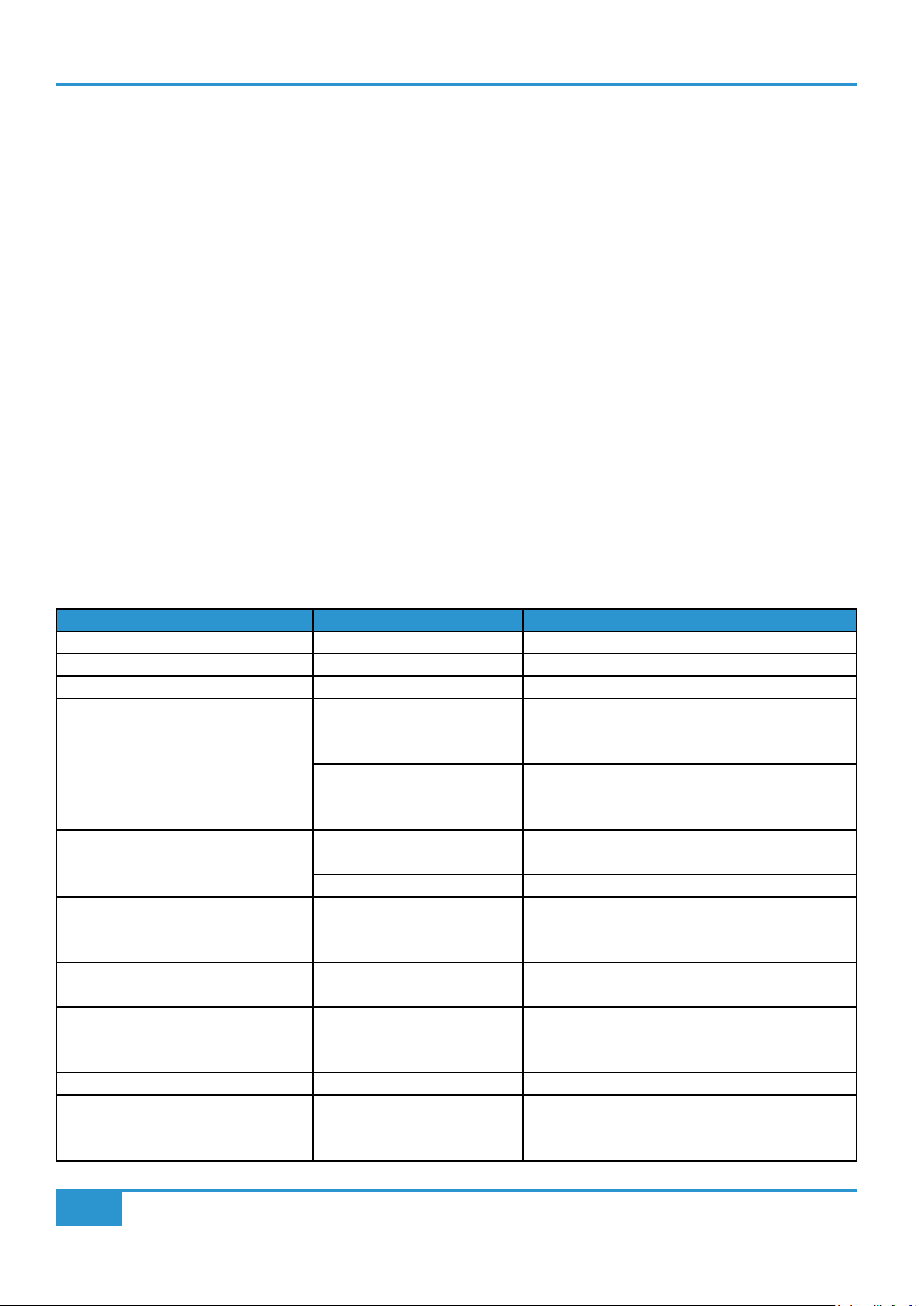
Troubleshooting 30
Specifications 32
General and Bus Compressor 32
D-EQ 33
Unit General 34
Block Diagram 35
The Bus+ Recall Sheet 36
Code-Break Master Game - Cheat Code 37
Safety Notices 38
THE BUS+ User Guide

Introduction
Overview
The Bus Compressor Legacy
If there is a single piece of analogue processing equipment that is synonymous with SSL, it just has to be The SSL Bus Compressor.
From the very first commercially released SSL 4000 B console in 1976 and through many generations of SSL consoles that have
followed since, the Bus Compressor has always been the stalwart of the console centre section. In 1991, when SSL took its first
steps into the analogue outboard world, the FX G384 saw the Bus Compressor put into rackmount form, meaning that studios
without SSL consoles could use it. In 2002, the FX G384 received a face-lift, with a new silver front panel taking it into the X Logic
era and this was followed by the multi-channel 5.1 version the following year. In 2007, the Bus Compressor became available as
double-width module for the X-Rack series and in 2013, the Bus Compressor made it's way into the ever-popular 500-series format.
Even if you've never had chance to experience SSL Bus Compressor 'in real life', then you will have undoubtedly come across it in
plug-in form, perhaps by using the SSL Native Bus Compressor 2. One thing is for sure, throughout the course of music production
history, the Bus Compressor has always been the de facto choice for gluing a mix together.
Creating The Ultimate
For the past two and a half years we've been hard at work engineering The Bus+, on a mission to create the ultimate and most
versatile incarnation of the Bus Compressor ever seen. The bedrock of the design remains faithful, as it always has done, to the
original circuit and using this base as the starting point, we've built upon it, adding a number of unique colouration options. If you
need it to be clean and punchy like the X Logic version, it can be. If you need it to be gritty and grungy like an early 4K, it can do
that also. Or, if you need to it to do something a little different, we've got you covered. To complement the new feature set, we also
sought to bring improvements that would benefit recallability and technical performance. Firstly, this led to a decision to make all
of the pots on The Bus+ stepped. Every pot is either an 11 or 31-position stepped control and this has the obvious advantage of
making recalls easier... but there's actually more cleverness going on here. Stepped pots on their own may make recalls easier
but simply using them instead of continuous pots doesn't lead to any technical advantage per se, as they are still subject to
mechanical tolerances that can compromise stereo matching and the overall analogue performance. So we went even further,
coming up with an innovative approach to the implementation. On The Bus+, all the stepped pot positions are read by an on-board
microcontroller, meaning that no audio actually passes through the pots themselves and by doing this, we are no longer subject
to the pot tolerances. The microcontroller's job is to translate the pot positions into the required circuit configuration or electrical
parameter. To be clear, The Bus+ is a 100% analogue circuit design, it's just managed in a clever way. This approach is extended
to the front panel buttons, providing clean and reliable switching of analogue signals thanks to the use of electronic switches.
In conjunction with the technical and general feature improvements, The Bus+ incorporates an all-new Dynamic Analogue Equaliser
section, which we've named the D-EQ. The D-EQ is a powerful 2-band Dynamic EQ that can be placed before or after The Bus
Compressor. Many engineers are familiar with Dynamic EQ plug-ins inside the DAW but analogue Dynamic EQs are few and far
between. A Dynamic EQ is a more 'intelligent' form of EQ that changes the gain of an EQ band proportionally in response to the
signal level once above a set threshold. It allows you to modify the contrast between background material (under threshold) and
forward material (above threshold). The D-EQ is built upon a specially adapted version of the Bus Compressor side-chain circuit,
which contributes significantly to its powerful, yet musical sonic character. Being able to use the D-EQ in conjunction with The Bus
Compressor makes for some very exciting dynamic and tonal options indeed.
To round off the design, we decided to give The Bus+ 4 unique operating modes. Alongside the known and loved Classic Stereo
mode, a � S/C Stereo mode is available, as found in our Duality console. Mid Side allows you to tailor the final mix/master stereo
image and Dual Mono is super useful for tracking purposes or creative stem use. The Bus+ is truly a treasure chest of compression
options at your disposal.
4
THE BUS+ User Guide

Introduction
Features
The Bus+ (General)
The Bus+ combines a feature-rich analogue SSL Bus Compressor with a powerful Dynamic EQ, all in a single 2U rack unit
➤ 100% analogue circuit, controlled digitally using the stepped front-panel pots
➤ 4 modes of operation - Classic Stereo, � S/C Stereo, Dual Mono or Mid-Side
➤ Huge +27.5 dBu headroom
➤ External side-chain inputs and sends
➤ Configurable processing order - Bus Compressor pre D-EQ (default) or post
➤ CH 1 IN and CH 2 IN buttons for global bypass
➤ Settable Operating Level - 0 dB (nominal), +10 dB, -5 dB
➤ Sleep and Auto-Sleep modes
Bus Compressor
The ultimate incarnation of the SSL Bus Compressor
➤ The authentic SSL Bus Compressor circuit utilising high-performance 2181 THAT VCAs
➤ LOW THD Mode reduces low-frequency distortion caused by compression
➤ F/B Mode alters the compression characteristics for a more 'relaxed' style of compression
➤ 4K Mode - single VCA operation with variable harmonic distortion to bring some 'grit' and 'grunge' to the mix
➤ Negative Ratios - for creative pumping effects and control of particularly loud signals
➤ New Attack and Release time constant options - more flexibility to shape the Bus Compressor, including the new
'Auto 2' setting
➤ Precision MDAC-controlled MAKE-UP Gain with two ranges available - 'Coarse' 1 dB steps or 'Fine' 0.5 dB steps
➤ Variable side-chain High-Pass Filter control up to 300 Hz in 10 Hz steps
➤ MIX control for instant parallel compression
➤ Moving-coil gain reduction meters
➤ Unlockable bonus mode: Transient Expander
D-EQ
An all-new, powerful 2-band analogue Dynamic EQ
➤ 2-band (LF and HF), parallel Dynamic Equaliser
➤ Compress/Expand modes
➤ 3 choices of time constants for each band - Nominal, FAST or AUTO.
➤ 16 selectable Frequency points per band
➤ Adjustable Range control per band from 0.5 dB to 15 dB
➤ HF band can be switched to Bell shape, with selectable frequencies covering High-Mids and Highs
➤ Frequency band static 'make-up' gain for LF and HF bands (Stereo/ � S/C Stereo) or LF band (Dual Mono/Mid-Side)
➤ G-Series mode changes LF filter to be 2nd order with degree of undershoot/overshoot
➤ Tri-colour activity LEDs to indicate D-EQ activity
➤ Individually bypass-able bands
THE BUS+ User Guide
5

Introduction
Unpacking
The unit has been carefully packed and inside the box you will find the following items.
➤ The Bus+
➤ IEC power cord for your country
➤ Safety Sheet
➤ Quickstart Guide
It is always a good idea to save the original box and packaging, just in case you ever need to send the unit in for service.
Rack Mounting, Heat and Ventilation
The Bus+ is a 2U, 19” rackmount piece of equipment designed to sit in the racking of a producer’s desk or similar. It is recommended
that ventilation space is left above and below the unit so any heat generated by The Bus+ can naturally disperse. The sides of
The Bus+ chassis have cut-outs that should under no circumstances be blocked or covered. Always allow The Bus+ to cool down
before handling.
Safety Notices
Please read the safety notice information included on the Safety Sheet inside the box before using The Bus+. This information is
also available in Appendices section of this User Guide.
6
THE BUS+ User Guide

Hardware Overview
Hardware Overview
This page provides a brief overview of The Bus+ hardware. The tutorial section covers each control in more detail.
Front Panel
BUS COMPRESSOR SWITCHES
Special Bus Compressor features,
unique to The Bus+ : LOW THD, F/B,
4K MODE.
BUS COMPRESSOR
CONTROLS
(BLUE KNOBS)
Bus Compressor side-chain, Mix
and Gain Make-up controls.
Rear Panel
MODE
Determines the mode of operation.
Choose from Classic Stereo, � S/C
Stereo, Dual Mono or Mid Side.
D-EQ CONTROLS
(BLACK KNOBS)
2-Band Dynamic Equaliser.
Controls for Compression/
Expansion and LF/HF Gain.
MOVING-COIL METER
Displays Gain Reduction for the Bus
Compressor or Frequency/Range settings
when configuring the D-EQ.
D-EQ SWITCHES
The array of 3-switches affect the time constants
of the Dynamic Equaliser side-chain (HF FAST, LF
FAST). The HF BELL changes the high-frequency
band filter from shelving to bell.
BALANCED XLR INPUTS &
OUTPUTS
Connect The Bus+ as a hardware
insert across your audio interface or
analogue desk.
Allows for creative duplication of the input signal. This could be used to feed an external
processing unit such as an EQ, returning the processed signal into the EXT S/C IN. Or, it could
be used to access the encoded Mid and Side signals, when using the unit in Mid Side mode.
EXT S/C IN - EXTERNAL SIDE-
CHAIN INPUTS
Connect external sources you would
like to trigger the side-chain from.
EXT SEND - SIDE-CHAIN SEND
AUTO-RANGING POWER SUPPLY
Simply connect the IEC to a mains
power socket and use the rocker switch
to power on/off.
THE BUS+ User Guide
7

Tutorial
Tutorial
MODE Selection
The Bus+ has four different modes of operation to choose from.
Pressing the MODE switch will move you through the options.
CLASSIC STEREO - This is the classic mode of operation for the SSL
Bus Compressor. Designed to be used on stereo sources, the controls
on the left-hand side of the unit determine the settings of both left
and right channels. The right hand controls are disabled and have no
function associated to them in this mode (with the exception of the LF/
HF GAIN D-EQ control).
� S/C STEREO - An alternative stereo mode of operation. The controls on the left-hand side of the unit determine the settings
of both left and right channels. In this mode, the left and right side-chain signals are summed together, as opposed to being
individually rectified. The effect of this is that the Bus Compressor becomes 'more sensitive' towards mono content in a stereo
source - typically instruments like kick, snare, bass. Have a go at switching between CLASSIC STEREO and � S/C STEREO to
see which you prefer on the material you're compressing.
A short press and hold on the MODE switch allows you to 'go backwards' through the modes, useful for A/B'ing
between two adjacent options.
In CLASSIC STEREO or �S/C STEREO, the right-hand side LF/HF GAIN control functions as the High Frequency Gain control
for both left and right (linked) channels. This is indicated by the red LED that accompanies the control (see illustration above).
In DUAL MONO or MID SIDE mode, the right-hand side LF/HF GAIN control functions as the Low Frequency Gain control for
Channel 2. This means that HF GAIN is only accessible in CLASSIC STEREO or �S/C STEREO modes.
DUAL MONO - This mode configures the Bus Compressor as two entirely independent mono processing engines. The controls
on the left-hand side determine the settings for channel 1 and the right-hand side controls determine the settings for channel 2.
MID SIDE - The Bus+ has built-in Mid-Side encode-decode circuitry that allows the left-hand side of the unit to process the 'Mid'
signal and the right side of the unit to process the 'Side' signal. This mode is a great tool for Mastering engineers.
CH 1 IN and CH 2 IN Switches
These switches allow you to bypass all Bus Compressor and D-EQ
processing. In stereo modes, the CH 2 switch is disabled as CH 1 controls
both left and right channels.
8
THE BUS+ User Guide

Overload (Clipping) Indication
The CH 1 IN and CH 2 IN switches will indicate if the headroom of
the unit has been exceeded by flashing red when the signal passing
through the unit registers above 26.5 dBu (i.e. 1 dB below absolute
headroom of +27.5 dBu). Overload detection is done at the output
of every internal circuit that has potential to introduce gain or to be
overloaded, including the EXT S/C IN. If this happens you may need
to reduce the MAKE-UP Gain, or indeed the level coming into The Bus+.
Mid Solo and Side Solo
(Mid Side Mode Only)
When The Bus+ is in MID SIDE Mode, pressing and holding the CH
1 IN switch will allow you to solo the Mid signal and pressing and
holding the CH 2 IN switch will allow you to solo the Side signal.
Tutorial
The switch will flash yellow to indicate the solo.
Press and hold the switch again to release the solo.
There are two different ways to listen to the solo'd Side signal,
depending on your preference. By default, the Side signal is presented
on both left and right outputs, in phase when solo'd. This can be
changed in the Settings menu to be presented after passing through the M/S decoder (i.e. Side signal out-of-phase on right output).
Sleep Mode
You can put the unit into SLEEP mode by pressing and holding both
the CH 1 IN and CH 2 IN switches together for 2 seconds or until they
start flashing. Sleep mode puts the unit into a very low power state (<
1 Watt), shutting down the audio rails until the unit is woken from sleep.
Simply press the MODE switch to wake The Bus+ from sleep.
Gain Reduction Meters
The Bus+ features two traditional moving-coil meters. These meters are
used to display the gain reduction in dB of the signals being compressed.
When operating the unit in a stereo mode, by default the right-hand side
meter is disabled and all activity is shown on the left-hand side meter.
However, you can enable the right-hand side meter if you wish via the
Settings mode.
The meters are also used to indicate the Frequency and Range settings of
the Dynamic EQ (D-EQ). Please see the D-EQ section the User Guide for
more information.
THE BUS+ User Guide
9

Tutorial
Bus Compressor Controls
THRESHOLD - Determines the level at which compression occurs. 31-position
stepped pot ranging from -20 to +20 dB.
ATTACK - Sets the attack time of the compressor (in milliseconds). 11-position
stepped pot ranging from .1 to 40 ms. The Bus+ features a number of Attack
time options never before seen on an SSL Bus Compressor, including 6, 15,
20 and 40 ms.
RATIO - Sets the ratio of the compressor. 11-position stepped pot ranging
from 1.3:1 to -0.5:1. The last three positions (-2.5, -1.5 and -0.5) are negative
ratios. A negative ratio is a setting whereby the output signal level is reduced
once it exceeds the threshold, to a level that goes below that of the threshold.
Negative ratios can be used to better control material that features extremely
loud signals or, they can be used for creative 'pumping' effects.
RELEASE - Sets the release time of the compressor (in seconds). 11-position stepped pot ranging from .05 to 1.2 seconds plus
two automatic release settings. For the first time on an SSL Bus Compressor, a fast release time of .05 (50 ms) is offered, as well
as a .15 s option. AUTO is the same automatic option as found on all other SSL Bus Compressor, suitable for complex material as
the release circuitry has a two-stage release (100 ms short, 12 seconds long). This means that louder elements of the signal are
released quickly and quieter elements more slowly. AUTO 2 (50 ms short, 6 seconds long), is a new option, providing a slightly
more 'active' automatic setting.
MAKE-UP - A gain make-up control allows for any changes to level introduced by compression to
be offset. Unity gain ('0') is marked in a white box on the front panel. The default range of the pot
is -10 to +20 dB, controlled via a 31-position stepped pot in 1 dB increments.
MAKE-UP [FINE] - A press and hold of the MAKE-UP control, allows for the control to work in
finer increments of 0.5 dB, with a range of -5 to +10 dB. The green LED below [FINE] lights to
indicate this mode is active.
POST D-EQ - By default, the signal process order of The Bus+ is Bus Compressor, followed by the
D-EQ circuit. A short press on the MAKE-UP control moves the Bus Compressor to be positioned
after the D-EQ. The green LED below POST D-EQ lights to indicate this mode is active.
A single push for POST D-EQ
processing or press and hold
to put MAKE-UP into FINE
mode
Press and hold MAKE-UP to
activate FINE mode
10
Press MAKE-UP to
activate POST D-EQ
processing order
THE BUS+ User Guide

S/C HPF (SIDE-CHAIN HIGH-PASS FILTER)
Introduces a 12 dB/oct (2nd order) High-Pass Filter into the compressor side-chain. 31-position
stepped pot ranging from OUT (fully counter-clockwise) to 300 Hz (fully clockwise). Steps are
in 10 Hz resolution.
MIX
Allows the dry (uncompressed) and wet (compressed) signal paths to be blended together.
31-position stepped pot range from DRY (fully counter-clockwise) to WET (fully clockwise).
By default, the control cross-fades between dry and wet paths but this can be altered in the
Settings menu to be a parallel control - i.e. the dry level is always kept at 100% and the wet
level 'fader' is brought up as you move the control towards WET, before switching to fully wet
only at the fully counter-clockwise position.
Tutorial
Please note that MIX only applies to the Bus Compressor part of The Bus+. D-EQ is
unaffected by the MIX control.
LOW THD
Most compressors by their nature start distorting low frequencies before high ones, particularly
when set for fast release times. Sometimes this forms part of the desirable 'analogue character'
but other times it is counter-productive. Pressing the LOW THD switch on The Bus+ introduces
a special circuit modification in the side-chain, helping to limit the amount of low frequency
distortion. Subjectively, LOW THD 'cleans up' the bottom-end, allowing you to achieve 'cleaner'
gain reduction than without it. Give it a try on your mix and see if you like it!
The graph to the left compares LOW THD
mode disabled vs enabled with a +4 dBu
test signal.
Bus Compressor settings:
Threshold 0 dB, Ratio 10:1, Attack 0.1 ms,
Release 0.1 s, Make-Up 0 dB.
THE BUS+ User Guide
Note how the distortion at low frequencies is
reduced with LOW THD enabled.
11

Tutorial
F/B (FEED-BACK) MODE
Although the Bus Compressor side-chain per se has a 'feed-back' topology, the signal feeding
the side-chain is derived from a feed-forward position. Engaging the F/B switch derives the
signal feeding the side-chain from a feed-back position (i.e. after the main gain-reduction
VCA in the audio path). This results in a more 'relaxed' style of compression, in contrast to the
traditional 'grab' of the Bus Compressor.
Usefully, because the MAKE-UP Gain on The Bus+ is implemented using an MDAC gain
stage (post feed to side-chain), instead of via the VCA (pre feed to side-chain)
4K MODE
When 4K MODE is disabled, the main VCA operates in a balanced configuration, optimised
for low noise and distortion. This is the approach of all modern SSL SuperAnalogue Bus
Compressor designs found in Duality & AWS consoles.
Engaging 4K MODE does two things. Firstly, it changes the operation of the VCA from balanced
to unbalanced (matching how the Bus Compressor in a 4000-series console was implemented)
and secondly, it introduces a variable amount of harmonic distortion via the VCA. These two
factors combine to allow for a more 'coloured' sound. Adjusting the distortion amount, you'll
find there's a certain 'sweet spot' (depending on your mix level) in which your material will
become more cohesive, thanks to the added thickness.
Since distortion is not achieved by means of overloading (amplification),
there is no inherent noise penalty from using 4K MODE even at the highest
distortion settings).
4K MODE - ADJUSTING THE DISTORTION SETTING
There are 9 levels of distortion to choose from. The current distortion setting is
indicated by the colour of the switch when 4K MODE is engaged. The Bus+
ships from the factory set to level 5 of 9.
To alter the distortion setting, press and hold the 4K MODE '[SET DIST]' switch
until it starts flashing. Then, use the - and + switches to decrease/increase
distortion. Press and hold the 4K MODE switch to finalise and return the - and +
buttons to their standard functions (LOW THD and F/B).
MIN
DISTORTION
DEFAULT
Press and hold 4K MODE until it starts to flash
Use the - and + keys to decrease or
increase the amount of distortion
MAX
DISTORTION
1 2 3 4 5 6 7 8 9
12
THE BUS+ User Guide

Selecting The External Side-chain Input
Pressing the S/C HPF control allows the external side-chain input(s) to be sourced for the Bus Compressor, D-EQ or both.
Ext S/C Input - Bus Comp
Ext S/C Input - D-EQ Ext S/C Input - Both Ext S/C Input - Off
Tutorial
Press once to select
the external input(s) as
the source for the Bus
Compressor side-chain.
Press twice to select the
external input(s) as the
source for the Dynamic EQ
side-chain.
Press three times to select
the external input(s) as
the source for both the
Bus Compressor and the
Dynamic EQ side-chains.
Press four times to return to
the default state of internal
side-chain for both the Bus
Compressor and Dynamic
EQ.
Going Further... Selecting the External Side-chain For One Dynamic EQ Band Only
When you select the external side-chain input for the Dynamic EQ, by default it is used for both the LF and HF bands. However,
you can choose to have one band driven from the external side-chain and the other from the internal side-chain.
External S/C Input For LF and HF
External S/C Input For HF Only External S/C Input For LF Only
Make sure D-EQ is selected as the
external side-chain source. Press
and hold the S/C HPF control and
you'll see the LF and HF Dynamic EQ
activity LEDs flashing green (default
state) - both bands driven by the
external side-chain input.
THE BUS+ User Guide
Whilst keeping the S/C HPF control
held down, press the LF control.
This will return the LF band to being
sourced from the internal side-chain,
whilst the HF band remains triggered
from the external side-chain input.
The HF D-EQ LED turns red to
indicate this.
Alternatively, keep the S/C HPF
control held down, press the HF
control. This will return the HF band to
being sourced from the internal side-
chain, whilst the LF band remains
triggered from the external side-chain
input. The D-EQ LED turns orange to
indicate this.
13

Tutorial
Dynamic Equaliser (D-EQ)
Many engineers use regular ('static') EQ in addition to their master bus compression, often feeling that they need to compensate
for the psychoacoustic perception of 'dulling' that compression can bring. Also, in general, many engineers apply a static EQ
across their mix as part of their mixing template to help achieve the level of bass and presence that modern productions require.
A Dynamic EQ, however, is a more 'intelligent' form of EQ which changes the gain of an EQ band proportionally in response to
the signal level once above a set threshold. Dynamic EQs allow you to modify the contrast between background material (under
threshold) and forward material (above threshold). Whilst putting together the concept for The Bus+, we wanted to build in a
Dynamic EQ that could be applied either before or after compression. After a considerable amount of research and development,
we came up with a design for the first-ever SSL Dynamic EQ - the D-EQ. The side-chain is a specially adapted version of the Bus
Compressor side-chain with additional circuitry such as the gain reduction limiter for the Range parameter. We think the D-EQ is
every bit as musical and powerful as the Bus Compressor itself. Some people may think of dynamic EQ as a tool fulfilling a similar
role to that of a multi-band compressor (without the cross-over phasing issues caused by band-splits of a multi-band design),
which is definitely one way of looking at it. However, through exploring the power of the D-EQ, we are certain you will find many
more creative uses beyond this, particularly using the expansion to enhance source material.
D-EQ CONTROLS
The D-EQ is a 2-band (LF and HF) dynamic EQ, with both engines able
to be turned on/off (bypassed) individually. The default frequency of
the LF Shelf is 60 Hz. The default frequency of the HF Shelf is 6 kHz.
When the HF Shelf is changed to a Bell (using the HF BELL switch),
the default frequency is 4 kHz. All of these frequency points can be
adjusted - see the D-EQ Frequency & Range Selection section.
BAND ON/OFF
To turn an engine on/off, simply press the LF (low frequency) or HF (high
frequency) control. It's easy to tell if the band is on as the corresponding
D-EQ switches (LF FAST / HF FAST & HF BELL) will become backlit.
COMP/EXP
Each band has a 31-position stepped control labelled with COMP and
EXP at the extremes of the control. As you turn the control clockwise
from the centre position '0' (no effect), you start dialling in an
expansion effect. Moving the control anti-clockwise, you start dialling
in a compression effect. By turning the control in either scenario, you
are effectively lowering the Threshold of the D-EQ, therefore how far
you need to turn it before either expansion or compression happens
will be dependent on the signal level.
D-EQ Activity LEDs
Above the LF and HF D-EQ controls are tri-colour LEDs, indicating
'how much' dynamic EQ is being added/subtracted by fading
between off, green, orange and red colours. The green LED starts to
come on with 0.5 dB of activity, reaching full green colour with 5dB.
Full orange is recognising 10 dB of activity, whilst full red indicates 15
dB of processing is occurring.
A push on the control will toggle the band on/off.
Think of the activity LEDs as being the equivalent
feedback you get from the meter for the Bus
Compressor.
14
THE BUS+ User Guide

D-EQ Switches
By default, the LF and HF bands are first order (6 dB per/oct) shelving filters with nominal attack and
release times set in the D-EQ side-chain. However, the following switches allow for some different options:
HF BELL
Changes the filter type from shelf to bell for the HF band. Switching to this also changes the available
frequency points, providing the ability to apply EQ in the critical upper-mid-range - see Frequency Points
page for more information. Switch lights bright white to indicate HF BELL is active.
HF FAST
Changes the time constants of the HF D-EQ band to 1 ms attack, 50 ms release. Switch lights bright white
to indicate HF FAST is active. Nominal settings are 3 ms attack 50 ms release.
Pressing and holding the switch allows for a third AUTO setting to be chosen. Switch lights magenta to
indicate this. Time constants for AUTO are 10 ms Attack, AUTO release.
LF FAST
Changes the time constants of the LF D-EQ band to 10 ms attack, 50 ms release. Nominal settings are
30 ms attack,100 ms release. Switch lights bright white to indicate LF FAST is active
Tutorial
Pressing and holding the switch allows for a third AUTO setting to be chosen. Switch lights magenta to
indicate this. Time constants for AUTO are 10 ms attack, AUTO release.
LF/HF GAIN
The LF GAIN control (left-hand side of the unit) provides +/- 10 dB of boost or cut to the
low frequency band of the D-EQ. This is control over the 'static' band of the EQ. The LF
GAIN can be used to apply a boost/cut of 'regular' EQ to compensate for any dynamic EQ
activity. For instance, you may use the dynamic part of the EQ to compress the lows but
add back in a bit of LF GAIN to compensate. The control is a 31-position stepped control.
Think of LF/HF GAIN being the equivalent to MAKE-UP Gain control you have for
the Bus Compressor.
The LF/HF GAIN control (right-hand side) is the same as described for the LF GAIN (a
static EQ control) but the MODE of The Bus+ determines whether it is a static gain for the
LF or HF band.
For CLASSIC STEREO and � S/C STEREO, the control acts on the HF Band. This is
indicated by the G/HF LED being RED. Please note, this is the only parameter on the
right-hand side of the unit that is active in either of the stereo modes.
For DUAL MONO or MID SIDE modes, the control acts on the LF band. The colour of the
G/HF LED may be either not lit or green in this mode but this is simply reflecting whether
the 'G-Series' mode is active or not - see next page.
THE BUS+ User Guide
Red LED indicates the control
functions as HF GAIN
15

Tutorial
G (G-Series) Mode
Pushing the LF GAIN control will toggle G (G-Series) mode on/off for the LF band. When
active, the LED lights GREEN.
When the EQ is in G-Series mode, the filters are changed from 1st order to 2nd order (12 dB
per octave) and an amount of overshoot/undershoot is added to the shelving filters above
the frequency cut-off point, similar to that found on G-Series SSL EQs. This can provide a
slightly different sonic character to the EQ which we have found to be pleasant on sources
like drum busses.
Please note this is only available for the LF GAIN band, not the HF band (stereo modes only).
G-Series Mode Graph
Undershoot at frequency cut-off point with G-Series mode engaged.
16
THE BUS+ User Guide

Tutorial
D-EQ - Frequency & Range Selection
For each band of the D-EQ, 16 different frequency points can be chosen from, allowing control over which part of the frequency
spectrum you want to affect. The D-EQ also allows control over a parameter called RANGE for each band. The RANGE parameter
allows you to restrict the maximum amount of expansion or compression possible, by introducing gain-reduction (or expansion)
limiting on the control voltage for the VCA in the D-EQ.
Adjusting the Frequency
Press and hold on the band (LF or HF) you want to change. The moving-coil meters on the front panel will start pulsing/glowing.
The left-hand side meter is used to indicate the selected frequency. Pressing the HF FAST switch will move the frequency point
upwards, whilst pressing the LF FAST button will move it downwards. The left-hand side meter needle shows the current setting.
Press and hold the LF (or HF control if you're adjusting that band) or the MODE switch to exit.
Press and hold desired band.
Use + or - keys to change
frequency.
The needle indicates the chosen frequency.
See next page for frequency points.
Adjusting the Range
(Presuming you are have already entered the setup mode by pressing and holding the LF or HF control):
Pressing the HF FAST switch will increase the Range of the D-EQ, whilst pressing the LF FAST button will decrease it. The right-
hand side meter needle shows the current Range setting. Press and hold the LF (or HF control if you're adjusting that band) or
the MODE switch to exit.
Press and hold desired band.
THE BUS+ User Guide
Use + or - keys to change Range
setting.
The needle indicates the chosen Range.
17

Tutorial
Frequency Points
The illustrations below show you the frequency to which each needle position corresponds to. The default frequency of the LF Shelf
is 60 Hz. The default frequency of the HF Shelf is 6 kHz. The default frequency of the HF Bell is 4 kHz.
LF
HF
HF
BELL
The HF BELL filter is a Proportional Q design, reaching a Q value of 1.87 at maximum boost/cut (10dB). The Q is 1.04 at 5 dB.
18
THE BUS+ User Guide

Tutorial
Range Points
When setting the Range parameter of the D-EQ band, the right-hand side meter displays the current setting. There are 23 different
ranges values that can be chosen from. The minimum is a range of 0.5 dB and the maximum if 15 dB. Between 0.5 and 8 dB the
steps are in 0.5 dB and between 8 and 15 dB the steps are in 1 dB. Usefully, the markings already on the meter correspond directly
to the equivalent Range values.
For example, the needle is showing that the Range is set to 4 dB here.
THE BUS+ User Guide
19

Settings Mode & Factory Reset
Settings
There are a number of configurable settings available for The Bus+. To
access these, hold down the MODE key whilst The Bus+ is powering
on. Read through the information on the following pages to understand
which switches affect which particular setting.
When you are finished adjusting settings, press and hold MODE again
and the unit will power cycle back into the normal operating mode.
Brightness
8 levels of brightness are available for the switch lights. Use the LOW
THD and FB switches on the left-hand side of the unit to decrease/
increase the brightness. Factory setting: Level 5 of 8.
Relay Feedback
You can enable/disable the relay feedback (audible click when a
switch is pressed) of the switches. This affects the startup sequence
and normal operation. To switch between enabled and disabled,
press the 4K MODE switch on the left-hand side of the unit.
If 4K MODE is lit GREEN, relay feedback is enabled (default).
If 4K MODE is dimly lit white, relay feedback is disabled.
Press and hold the MODE key whilst The Bus+ is
powering on
Relay enabled
Relay disabled
Mix Control Mode - Classic or Parallel
The MIX control can work in two different ways. Classic mode
cross-fades between dry and wet signals, whilst Parallel mode
keeps the dry signal at 100% and brings up the wet 'fader' as the
control is rotated towards the fully-clockwise WET position. The
Parallel mode allows for NY style parallel compression very easily.
To switch between Classic and Parallel modes, push the
MAKE-UP control on the left-hand side of the unit.
FINE LED indicator GREEN = Classic mode (default).
FINE LED indicator ORANGE = Parallel mode.
When the Parallel setting is active, the MODE indicator LEDs
(Classic Stereo / � S/C Stereo / Dual Mono / Mid Side) illuminate
orange instead of green in normal operation, to give a useful
representation of this option being enabled. Also, with the Parallel
Mix option selected, turning MIX control fully CW will enable Audition mode (dry 0%, wet 100%). In this position, the currently
active MODE LED indicator will blink. Audition mode is useful as it allows you to tweak compressor parameters while listening to
the wet signal in isolation.
Classic mode Parallel mode
20
THE BUS+ User Guide

Settings Mode & Factory Reset
Operating Level - Input Gain Trim
The 4K MODE switch on the right-hand side determines if an Input Trim is applied. Press the switch to cycle through the options.
4K MODE = WHITE: 0 dB (default)
This is the standard operating level, generally suitable for most mixing scenarios.
4K MODE = RED: +10 dB
A 10 dB gain is applied to the input stage. This is useful when you are interfacing The Bus+ with an audio interface or DAC that
has a lower output level, allowing it to drive The Bus+ correctly. For example, this is recommended if connecting The Bus+ to an
SSL 2 audio interface which outputs +12.5 dBu at 0 dBFS.
4K MODE = GREEN: -5 dB
A pad of -5 dB is applied to the input stage. This operating mode might be useful for Mastering engineers dealing with 'hot' mixes,
effectively altering the threshold range from +20/-20 dB to +25/-15 dB.
0 dB Input Gain
+10 dB Input Gain -5 dB Input Gain
Auto Sleep
In addition to putting The Bus+ into Sleep mode manually (by pressing CH 1 IN and CH 2 IN switches together in normal operation),
the unit can enter Sleep mode automatically after a specified amount of time of inactivity. Inactivity can mean either the pots and/
or switches have not been operated. It can also mean there has been no audio present above -5 dBu at the Bus Compressor input
(with 0 dB input trim).
By default Auto Sleep is disabled. Engaging the left-hand side HF BELL switch enables Auto Sleep with a default setting of 20
minutes. Use the HF FAST and LF FAST switches to increase/decrease the activation time for Auto Sleep. Operating mode LEDs
(Classic Stereo / � S/C Stereo / Dual Mono / Mid Side) indicate the current Auto Sleep time setting.
1) Press HF BELL to enable Auto Sleep 2) Use HF FAST / LF FAST to increase or decrease Auto Sleep activation time
THE BUS+ User Guide
21

Settings Mode & Factory Reset
Deep Sleep & Waking Up
If the unit is in Auto Sleep mode, it's possible to make it wake up automatically simply by sending audio above 0 dBu. Alternatively,
simply press the MODE switch.
The Auto wake up function requires part of the audio circuitry to be still powered. After 1 hour of inactivity while in Auto Sleep, the
unit enters "deep sleep" (which is the same as putting the unit into Sleep mode manually) to save the most power (less than 1 watt
power consumption).
In Deep Sleep, the only available mean of restoring operation is by manually pressing the MODE switch.
In Auto Sleep a brief light animation on the operating mode LEDs occurs every few seconds helping you to identify you are in Auto
Sleep and not Deep Sleep.
Input Stage - Low Pass Filter
Some DACs or Audio Interfaces, depending on the implementation, can exhibit excessive out-of-band noise. Whilst you won't
directly hear it, it may cause unwanted triggering of Bus Compressor and D-EQ side-chains. When that happens, you'll notice the
gain reduction meter being displaced (or the D-EQ indicators lit) with no audio being played. It may also cause increased noise-
floor at high 4K MODE distortion settings.
To combat this, The Bus+ allows you to engage a 18 dB/oct (3rd order) Low Pass Filter at 26 kHz. If you have The Bus+ connected
to an audio interface that exhibits this issue, you may need to engage this. The filter is applied on every input stage, including
External Input(s).
You toggle the LPF by pressing the right-hand D-EQ LF control. The activity LED indicates if the LPF is in or out.
If the LF control LED is RED, then the LPF is disabled (default).
If the LF control LED is GREEN, then the LPF is enabled.
22
LPF disabled (default) LPF enabled
THE BUS+ User Guide

Settings Mode & Factory Reset
Side Solo Mode
In normal operation, the Side signal when solo'd is presented on both left and right outputs, in phase. This can be changed to
be presented after passing through the M/S decoder, which gives in-phase Side signal on the Left output and out-of-phase Side
signal on the Right output.
You toggle the Side Solo mode by pressing the CH 2 IN switch.
If the CH 2 IN switch is YELLOW, the Side signal is presented on both left and right outputs, in phase
If the CH 2 IN switch is ORANGE, the Side signal is presented after passing through the M/S decoder.
Side solo = left and right, in phase Side solo = presented through M/S decoder
Right-Hand Side Meter On/Off - Stereo Modes
By default, in normal operation if The Bus+ is in Classic Stereo or � S/C
Stereo modes then the right-hand side gain reduction meter is disabled.
However, this can be changed so that both meters light up and operate in
these stereo modes.
You toggle the right-hand side meter to be on/off in stereo modes pressing
the CH 1 IN switch.
If the CH 1 IN switch is DIM WHITE, the right-hand side meter is disabled in
stereo modes (default).
If the CH 1 IN switch is BRIGHT WHITE, the right-hand side meter is enabled
in stereo modes. The backlight of the right-hand side meter will also reflect
the current setting.
Right-hand side meter disabled Right-hand side meter enabled
THE BUS+ User Guide
23

Settings Mode & Factory Reset
Factory Reset
To return the unit to the factory-shipped state, you can perform a factory reset by following these instructions:
• Press and hold both channels' (left and right) LOW THD switches during the power-up sequence.
• When the switches in the centre of the unit start flashing RED, release the LOW THD switches and the unit will reboot
automatically with factory settings restored.
Press and hold both LOW THD switches during boot until central switches start flashing,
then release.
Be sure to release the LOW THD switches soon after the central switches start flashing red, or else you might
accidentally perform a Deep Factory Reset (see bottom of this page for more information).
Settings affected by Factory Reset:
• Switches states
• Shaft switches states
• Frequency and Range settings for LF/HF/HF BELL
• Brightness (default: 5th level over 8 total)
• Relay feedback (default: ON)
• Input trim (default: 0 dB)
• Autosleep On/Off (default: Off)
• Autosleep timeout (default: 20 min)
• LPF (default: disabled)
• Parallel Mix mode (default: disabled)
• Side Solo mode (default: in-phase)
• Right-hand side Meter On/Off in Stereo Mode (default: Off)
Deep Factory Reset
The Bus+ offers a 'Deep' Factory Reset, which is the same as the standard Factory Reset described above but it also resets the
Transient Expander to be unavailable/locked out. To unlock the Transient expander, you must once again win the built-in 'Code-
Break Master' game.
To perform a 'Deep Factory Reset', perform the same actions described for the standard Factory Reset but keep the switches
held for a few seconds longer, until the central switches start flashing GREEN, then release the LOW THD switches and the unit
will reboot automatically.
Please note that performing a Deep Factory Reset means that you will have to win a game of 'Code Break Master'
once more to unlock and be able to use the Transient Expander feature.
24
THE BUS+ User Guide

Code-Break Master Game
Code-Break Master Game
Can you break the code to unlock the Transient Expander?
Introduction
In true SSL tradition, the engineering team are pleased to bring you the Code-Break Master game built into The Bus+.
Aim Of The Game
The Bus+ randomly picks a sequence of 4-colours (from a palette of 6). You have 12 rounds to guess correctly (i.e. break the
code!). The number of guessing rounds you have remaining is indicated by the position of the left-hand side meter needle.
Entering The Game
Press and hold the left-hand side CH 1 IN, HF BELL, HF FAST and LF FAST switches whilst The Bus+ is powering on.
Press and hold these 4 switches whilst The Bus+ is
powering on to enter the Code Break Master Game Mode.
Starting The Game
The MODE switch will be pulsing red and the front panel LEDs swiping left and right, like a familiar 80's TV car's headlights. Press
the MODE switch to start the game.
THE BUS+ User Guide
THE BUS+ User Guide
25
25

Code-Break Master Game
How It Works
STEP 1 - Pick your colours
1. At the start of each game, The Bus+ randomly picks (but does not show!) a sequence of colours
for the CH 1 IN, HF BELL, HF FAST and LF FAST switches. Each of these switches could be one
of a six possible colours - Orange, Red, Green, Blue, Magenta and White.
2. Each round, you pick colours for each of these switches by toggling them to the ones you think
The Bus+ has picked. To change the combination of colours, simply press on any of the four
switches. A press and hold allows you to select the previous colour in the sequence.
3. Finalise your decision for that round by pressing the MODE switch.
STEP 2 - Hint (See how you did)
After finalising your decision for the round, The Bus+ will feedback information on how close (or not!)
you were to guessing the correct colour combination, using the 4 LEDs above CLASSIC STEREO, �
S/C STEREO, DUAL MONO and MID SIDE:
Off LED = You have picked a colour which is not present in the solution.
Red LED = You have picked a correct colour but it is in the wrong position.
Green LED = You have picked a correct colour AND it is in the correct position.
For example, 2 Red LEDs would mean you have correctly guessed the colour of 2 of the 4 switches
but they are both in the wrong position. Another example would be 1 Green LED and 3 Red LEDs,
meaning that one of the colours you have picked is correct (both for the colour and the position) and
the other 3 colours are correct but all in the wrong position. No LEDs lit means none of the colours you
have picked are present in the solution, in any position.
The image above shows what would be displayed if you had correctly guessed the colour and position of one switch (green)
and correctly guessed two other switches colours but in the wrong position.
Note: The position of the feedback LEDs is not related to the position of current guess.
Guess the colour
code The Bus+
has set for these
four switches
by toggling their
colours each round.
STEP 3 - Use the Feedback to adjust the colours you pick in the next round
Press the left-hand side F/B switch to move onto your next round of guessing, once again toggling
the CH 1 IN, HF BELL, HF FAST and LF FAST switches to the colours you think The Bus+ has
picked as the secret code.
Again, finalise your choices for this round by pressing the MODE key.
Press the F/B switch to begin your next round of
26
26
attempting to break the code.
THE BUS+ User Guide
THE BUS+ User Guide

Code-Break Master Game
Top Tip - Using the LOW THD and F/B Switches to Review Previous Guess Rounds
After the first round of guessing is complete the LOW THD switch becomes available, allowing you to go back through previous
guess rounds, to help make more informed decisions as the game progresses.
After the second round of guessing is complete, the F/B switch becomes available, which means you can then move backwards
(using the LOW THD) and forwards (using the F/B switch) to review the choices you have made in every round as the game
progresses. Use the F/B switch to get back to your latest round of guesses - the MODE key will once again become available to
finalise your choices in the current round.
Use the LOW THD and F/B switches to
review previous rounds of guesses.
Winning
If you manage to correctly match the combination of colours across the 4 switches in 12 rounds or less, then The Bus+ will flash
all front-panel LEDs GREEN.
Losing
If you fail to correctly match the combination of colours across the 4 switches before 12 rounds of guessing run out, then The Bus+
will flash all front-panel LEDs RED... but do not fear, simply press the MODE key twice to have another go!
Exiting The Game
Press and hold the right-hand side LOW THD switch to reboot the unit into normal operation.
The Prize - Unlocked Transient Expander Feature!
Congratulations on breaking the code. As a reward, you have unlocked the
Transient Expander feature. Returning The Bus+ to normal operation (press
and hold the right-hand side LOW THD switch), you will now be able to press
and hold the HF BELL switch to engage the Transient Expander feature turn
it GREEN.
When active, the HF control is no longer associated with the D-EQ (The
D-EQ HF band is temporarily sacrificed and instead, the HF control functions
as a Transient Expander control. Rotate the control from '0' (12 o'clock)
position means (no transient expansion) to fully clock-wise 'EXP' (maximum
expansion). Push the HF to toggle the Transient Expander in/out. The HF LED
lights green-orange-red, to give you an indication of how much expansion is
taking place when active.
THE BUS+ User Guide
THE BUS+ User Guide
Press and hold the HF BELL switch until it
turns green and then rotate the HF control
clockwise to start expanding.
27
27

Troubleshooting & FAQs
Bus Compressor Meter Calibration
The Bus+ can be put into Meter Calibration Mode. This mode allows the meter needles to be
calibrated for optimal alignment against the 4, 8, 12, 16 and 20 marks, when being used to display
the Frequency and Range settings of the D-EQ. To enter Meter Calibration Mode, hold down the left-
hand side LF FAST and HF FAST switches whilst The Bus+ is powering on.
Please note: Calibration only affects the D-EQ Settings mode (Frequency and Range) and not
the meter's normal operation/compression.
'0' Mark Calibration
Upon entering Meter Calibration Mode, the needle of both meters will be resting near the 0 position.
For this '0' position only, you should use the front panel flat-head screwdriver adjustment to move the
needles closer to their 0 positions if necessary.
Press and hold LF and
HF FAST switches to
enter Meter Calibration
Mode whilst The Bus+ is
powering on.
Use a flat-head screwdriver to adjust needle
position for the '0' marking only.
'4' Mark Calibration
When you are happy with the '0' mark calibration, press the left-hand side side F/B switch to move onto
the calibration for the '4' mark, the meter needles move towards '4'. Next, use the left-hand side LF FAST
/ HF FAST switches to move the left-hand side needle as close to the '4' marking as you can. LF FAST
moves the needle down and HF FAST moves the needle direction up. Do the same for the right-hand
side meter, using the right-hand side LF FAST / HF FAST switches.
Use the F/B
switch to move
to the next
calibration point.
28
Use the LF FAST or HF FAST
switches to move the needle
towards the mark.
THE BUS+ User Guide

Troubleshooting & FAQs
Calibration Marks '8', '12', '16', '20'
When you are happy with the '4' mark calibration, repeat the same process to line up marks
'8', '12', '16' and '20' as closely as you can using the LF FAST and HF FAST switches. Use
the left-hand side LOW THD and F/B switches to go to the previous or next line-up positions,
should you want to make any changes.
Use the LOW THD and F/B
keys to move to the previous or
next calibration mark.
Calibration Marks Indication
In addition to the Bus Compressor Meter Needle moving towards each mark, the following LEDs light red to indicate which mark
is currently being calibrated:
• EXT S/C D-EQ Left LED = 0 dB mark mechanical alignment
• Classic Stereo = 4 dB mark calibration
• Sum SC Stereo = 8 dB mark calibration
• Dual Mono = 12 dB mark calibration
• Mid Side = 16 dB mark calibration
• EXT S/C Comp Right = 20 dB mark calibration
Saving The Calibration
Important: To save the current calibration and exit, press and hold the
MODE key and the unit will power cycle. If you simply power cycle the
unit from the mains switch, the calibration will not be saved!
Press and hold the MODE key to save the calibration.
THE BUS+ User Guide
29

Troubleshooting & FAQs
Troubleshooting
UID Display
UID Display Mode displays the UID number of the firmware currently in use and the hardware
revision of both main card and front panel card. To enter UID Display Mode, press and hold the
left-hand side F/B switch during the power-up sequence.
Number of digits for each item:
• Firmware UID: 5 digits number
• Mainboard HW revision: 1 digit number
• Frontpanel HW revision: 1 digit number
Digit selection is performed via dedicated switches:
FW UID 1st digit: Low THD Left
FW UID 2nd digit: FB Left
FW UID 3rd digit: 4K MODE Left
FW UID 4th digit: 4K MODE Right
FW UID 5th digit: FB Right
Main board HW revision: LF FAST Left
Front panel HW revision: LF FAST Right
Once the required digit is selected, the information is obtained by counting the number of indicator LEDs lit up GREEN.
E.g. if the current digit is “3”, this will be indicated by POST D-EQ , MAKEUP FINE , EXT S/C COMP LEDs all lighting green.
The indicators involved in this process are as follows (in increasing order):
• POST D-EQ L (1)
• MAKEUP FINE L (2)
• EXT S/C COMP L (3)
• EXT S/C DEQ L (4)
• CLASSIC STEREO (5)
• SUM SC STEREO (6)
• DUAL MONO (7)
• MID SIDE (8)
• EXT SC COMP (9)
If no indicator is lit, the current digit is “0”.
To exit, press and hold the MODE key and the unit will power cycle.
30
THE BUS+ User Guide

Troubleshooting & FAQs
Soak and Potentiometer Test Mode
Soak mode is used to check the correct operation of all lights and indicators on front panel. It
cycles through the phases listed below. To enter Soak mode, hold down the left-hand side 4K
MODE switch whilst The Bus+ is powering on.
1. All switches lights bright white
2. All switches lights red, if available (otherwise dim white)
3. All switches lights green, if available (otherwise dim white)
4. All switches lights blue, if available (otherwise dim white)
5. All indicators lit up green
6. All indicators lit up orange
7. All indicators lit up red
8. Left VU Meter back light pulse + needle sweep
9. Right VU Meter back light pulse + needle sweep
In this mode it’s also possible to test the correct operation of the potentiometers. A position change on any of the pots will trigger
the relay to click as a confirmation feedback.
To exit, press and hold the MODE key and the unit will power cycle.
Power Check
The Bus+ has a built-in system to self-check most of the internal power supply rails. If a fault is detected at any time, all the rails
are shutdown for safety and a user warning is triggered on the front panel via the 4 center section indicators:
CLASSIC STEREO blinking red: detected a fault on the +16V rail
SUM SC STEREO blinking red: detected a fault on VPOT rail
DUAL MONO blinking red: detected a fault on +15V rail
MID SIDE blinking red: detected a fault on negative rails (combination of +/- 16V_RAW, -15V, -16V)
Once a fault is detected, it’s possible to manually trigger the reboot of the unit by pressing MODE for 1 second. If the unit keeps
failing the power check, please get in contact with SSL support.
THE BUS+ User Guide
31
Appendices
Specifications
General and Bus Compressor
Default test conditions (unless otherwise stated):
Source impedance of test set: 40 Ω
Input impedance of test set: 100 kΩ
Reference frequency: 1 kHz
Reference level: 0 dBu
All unweighted measurements are specified as 20 Hz to 20 kHz bandwidth limited, expressed in dBu
Onset of clipping (for headroom measurements) should be taken as 1% THD
Measurements taken with default input trim setting (0 dB)
All levels are intended balanced
Mode set to Classic Stereo
D-EQ modules bypassed
Mix pot set fully wet
LPF disabled
4K Mode, LOW THD, F/B: disabled
Threshold +20 dB
Unless otherwise quoted all figures have a tolerance of ±0.5dB or 5%.
Audio Performance
Measurement Value Conditions
Input Impedance 10 kΩ -
Output Impedance 60 Ω -
Maximum Input & Output Level +27.5 dBu Operating Level Modes 0 dB/-5 dB, 1% THD
Frequency Response ±0.025 dB
< 1 Hz
> 200 kHz
±0.01 dB
< 2 Hz
> 180 kHz
THD+N -95 dB / 0.0017% typical
-106 dB / 0.0004% typical
-88 dB / 0.004% typical Compressor In, 1 kHz @ 0 dBu
Noise -95 dBu typical
-90 dBu typical
-89 dBu typical
Dynamic Range 122.5 dB
117.5 dB
Crosstalk < -118 dB
< -110 dB
< -90 dB
Make-Up Gain Precision < 0.003 dB - 10 dB to + 20 dB
Stereo Matching < 0.05 dB
< 0.02 dB
< 0.1 dB
Bypassed, 20 Hz to 20 kHz
Bypassed, -3 dB low cut-off
Bypassed, -3 dB high cut-off
Compressor In, 20 Hz to 20 kHz
Compressor In, -3 dB low cut-off
Compressor In, -3 dB high cut-off
Bypassed, 1 kHz @ 0 dBu
Bypassed, 1 kHz @ +20 dBu
Bypassed
Compressor In
4K Mode In (any intensity)
Bypassed
Compressor In
Bypassed, 20 Hz @ +24dBu
Bypassed, 1 kHz @ +24 dBu
Bypassed, 10 kHz @ +24 dBu
Bypassed
In, 1 kHz @ 0 dBu
Dual Mono, any setting gain reduction <8 dB
32
THE BUS+ User Guide

D-EQ
Default test conditions (unless otherwise stated):
Source impedance of test set: 40 ohm
Input impedance of test set: 100 kOhm
Reference frequency: 1 kHz
Reference level: 0 dBu
All unweighted measurements are specified as 20 Hz to 20 kHz bandwidth limited, expressed in dBu
Onset of clipping (for headroom measurements) should be taken as 1% THD
Measurements taken with default input trim setting (0 dB)
All levels are intended balanced
Mode set to Classic Stereo
D-EQ modules bypassed
Mix pot set fully dry
LPF disabled
LF/HF Gain pot set to center
LF/HF pots set to center
LF maximum frequency
HF minimum frequency
Unless otherwise quoted all figures have a tolerance of ±0.5dB or 5%.
Appendices
Audio Performance
Measurement Value Conditions
Frequency Response (20 Hz - 20 kHz) ±0.05 dB
< 2 Hz
> 200 kHz
±0.05 dB
< 2 Hz
> 200 kHz
THD+N -88 dB / 0.004% typical
-81 dB / 0.008% typical
Headroom > 27 dB LF In, HF In
Noise -90 dBu typical
-87 dBu typical
LF Gain Accuracy
HF Gain Accuracy
Stereo Matching < 0.05 dB
±0.05 dB typical
±0.05 dB typical
< 0.1 dB
< 0.1 dB
LF In, 20 Hz to 20 kHz
LF In, -3 dB low cut-off
LF In, -3 dB high cut-off
HF In, 20 Hz to 20 kHz
HF In, -3 dB low cut-off
HF In, -3 dB high cut-off
LF In, 40 Hz @ 0 dBu
HF In, 10 kHz @ 0 dBu, 40 kHz BW
LF In
HF In
LF In, 40 Hz @ 0 dBu: -10 dB to +10 dB
HF In, 10 kHz @ 0 dBu: -10 dB to +10 dB
LF/HF In, 20 Hz to 20 kHz @ 0 dBu
LF In, 40 Hz, any gain change
HF In, 10 kHz, any gain change
THE BUS+ User Guide
33

Appendices
Unit General
Power
Power Supply Auto-Ranging 100-240 VAC
Operating Power 38 Watts
Sleep Power < 1 Watt
Auto-Sleep Power 10 Watts
Physical
Width 480 mm / 19 inches
Height 88.9 mm / 3.5 inches (2 RU)
Depth 303 mm / 11.9 inches (chassis only)
328 mm / 12.9 inches (total including front panel controls)
Weight 5.92 kg / 13.1 lbs
Boxed Dimensions 550mm x 470mm x 225mm (21.7" x 18.5" x 8.9")
Boxed Weight 8.68 kg / 19.14 lbs
Connectors
Inputs Female XLR x2
External Inputs Female XLR x2
Outputs Male XLR x2
External Sends Male XLR x2
34
THE BUS+ User Guide

Block Diagram
*PUSH FOR FINE*
LF COMP/EXP
HF COMP/EXP
Appendices
MAKE-UP
*PUSH FOR FINE*
MAKE-UP
OUT 2
-
+
CH 2
IN/OUT
(BYPASS)
BELL
-
+
-
+
FREQ & RANGE
HF GAIN
HF COMP/EXP FAST
D-EQ
*PUSH ON/OFF* *PUSH ON/OFF*
LF COMP/EXP FAST
D-EQ
POST
MIXMIX
MDAC
-5 to +10
-5 to +10
-10 to +20
-10 to +20
+
+
FREQ & RANGE
LF GAIN
HF
EXT
-
-
LF
EXT
OUT 1
-
+
L M
M L
M/S ENCODEM/S DECODE
CH 1
IN/OUT
(BYPASS)
BELL
-
+
-
+
FAST
FREQ & RANGE
HF GAIN
D-EQ
FAST
*PUSH ON/OFF* *PUSH ON/OFF*
D-EQ
POST
MIXMIX
MDAC
-5 to +10
-5 to +10
-10 to +20
-10 to +20
+
+
FREQ & RANGE
LF GAIN
HF
EXT
-
-
LF
EXT
EXT
SEND 1
-
+
L MS R
EXT
SEND 2
-
+
EXP
TRANSIENT
RATIO
VCA
VCA
2181
2181
*PUSH ON* *PUSH ON*
ATTACK RELEASE THRESHS/C
ATTACK RELEASE THRESHS/C HPF
4K MODE
LOW THD
LOW THD
*PUSH FOR XG*
*PUSH FOR EXT*
∑ S/C
VCA
VCA
2181
2181
EXP
TRANSIENT
RATIO
*PUSH ON* *PUSH ON*
ATTACK RELEASE THRESHS/C
ATTACK RELEASE THRESHS/C HPF
4K MODE
LOW THD
LOW THD
*PUSH FOR XG*
*PUSH FOR EXT*
∑
CONTROL
EXT S/C
PUSH S/C HPF
F/BF/B
-5
+10
-5 to +10
-2.5 to +5
0 (Nominal)
TO CHANGE
INPUT GAIN
ENTER SETTTINGS MENU
LPF
TO CHANGE
ENTER SETTTINGS MENU
26 kHz
M/S
-
-
+
+
IN 1
-5
+10
-5 to +10
-2.5 to +5
0 (Nominal)
26 kHz
L M
L M
M/S ENCODEM/S ENCODE
-
+
EXT
S/C
IN 1
-5
+10
-5 to +10
-2.5 to +5
0 (Nominal)
L M
R S
EXT S/C
F/BF/B
-5
+10
-5 to +10
-2.5 to +5
0 (Nominal)
26 kHz
-
-
+
+
IN 2
26 kHz
-
+
EXT
S/C
IN 2
Directly Actionable Switch
KEY
Subsequent switches
always action in
response to first
Stereo Linking Possible
directly actionable switch
THE BUS+ User Guide
35

Appendices
The Bus+ Recall Sheet
Track
_____________________________________________________________
Artist
_____________________________________________________________
Producer
_____________________________________________________________
Notes
_________________________________________
_____________________________________________________________
_________________________________________
_____________________________________________________________
36
_____________________________________________________________
_____________________________________________________________
_____________________________________________________________
THE BUS+ User Guide

Appendices
Code-Break Master Game - Cheat Code
Unlock the Transient Expander (Cheat)
Desperate to try the Transient Expander but don't have the patience to win a game of Code-Break Master? Read on to discover
how to unlock the Transient Expander without having to win the Code-Break Master game...
Power on the unit whilst holding the MODE key down to enter
SETTINGS mode.
Press and hold the MODE key whilst The Bus+ is
powering on
Press and hold the right-hand side HF BELL key for 2 seconds to toggle Transient
Expander Mode on/off.
If HF BELL is lit GREEN, then Transient Expander Mode is enabled.
If HF BELL is dimly lit white, Transient Expander mode is disabled.
See the bottom of Page 27 for more details on this mode.
Press and hold the right-hand side HF BELL key for 2
seconds to turn on Transient Expander Mode.
THE BUS+ User Guide
37

Appendices
Safety Notices
General Safety
• Please read and keep this document.
• Adhere to all warnings and follow instructions.
• This electrical equipment should not be used near water, rain or moisture.
• Clean only with dry cloth or products compatible with electrical devices and never when the unit is powered.
• Keep the unit free of dust and use in a clean environment.
• Do not use near any heat source, indirect sunlight or naked flames.
• Do not place heavy objects on the unit.
• Only use attachments/accessories recommended by the manufacturer.
• Unplug the device during lightning storms or long periods of non-use.
• The unit can only be serviced by qualified personnel – seek immediate service if:
- The unit has been exposed to moisture
- The unit has been dropped
- The unit does not operate normally
• Do NOT modify this unit, alterations may affect performance, safety and/or international compliance standards.
• SSL does not accept liability for damage caused by maintenance, repair or modification by unauthorised personnel.
Installation Notes
• When installing this apparatus either fix it into a standard 19” rack or place it on a secure level surface.
• If the unit is rack mounted, fit all rack screws. Rack shelves are recommended.
• When rack mounting, allow a 1U gap above and below the unit for cooling.
• Ensure that no strain is placed on any cables connected to this apparatus. Ensure that all such cables are not placed where
they can be stepped on, pulled or tripped over.
Power Safety
• Bus+ is supplied with a mains lead however if you wish to use a mains cables of your choice it must comply with the following
standards:
- Refer to the rating label on rear of the unit and always use a suitable mains cord.
- The unit should ALWAYS be earthed.
- Please use-compliant 60320 C13 TYPE SOCKET. When connecting to supply outlets ensure that appropriate sized
conductors and plugs are used to suit local electrical requirements.
- Maximum cord length should be 4.5m(15’).
- The cord should bear the approval mark of the country in which it is to be used.
• The appliance coupler is used as the disconnect device, ensure that it is connected to an unobstructed wall outlet.
• Connect only to an AC power source that contains a protective earthing (PE) conductor.
• Only connect units to single phase supplies with the neutral conductor at earth potential.
DEN Apparatets stikprop skal tilsluttes en stikkontakt med jord, som giver forbindelse til stikproppens jord.
FIN Laite on liitettävä suojamaadoituskoskettimilla varustettuun pistorasiaan.
NOR Apparatet må tilkoples jordet stikkontakt.
SWE Apparaten skall anslutas till jordat uttag.
38
THE BUS+ User Guide
Appendices
CAUTION!
This equipment must be Earthed. Refer to the manual for installation instructions. Disconnect all power
sources before removing any panels. No user-serviceable parts inside - to be serviced only by qualified
personnel.
WARNING!
Un-earthed metal parts may be present inside the enclosure. Check for hazardous voltages before touching.
UKCA & EU Compliance
This product complies with the following European Union Harmonisation Legislation:
Electromagnetic Compatibility directive (EMC) 2014/30/EU.
Low Voltage directive (LVD) 2014/35/EU.
RoHS notice
Solid State Logic has conformed and this product has conformed to European Union’s Directive 2011/65/EU on Restrictions of
Hazardous Substances (RoHS) as well as the following sections of California law which refer to RoHS, namely sections 25214.10,
25214.10.2, and 58012, Health and Safety Code; Section 42475.2, Public Resources Code.
Instructions for disposal of WEEE by users in the European Union
The symbol shown here, which is on the product or on its packaging, indicates that this product must not
be disposed of with other waste. Instead, it is the user’s responsibility to dispose of their waste equipment
by handing it over to a designated collection point for recycling of waste electrical and electronic
equipment. The separate collection and recycling of your waste equipment at the time of disposal will help
to conserve natural resources and ensure that it is recycled in a manner that protects human health and
the environment. For more information about where you can drop off your waste equipment for recycling,
please contact your local city office, your household waste disposal service or where you purchased the
product.
FCC Certification
This device complies with part 15 of the FCC Rules. Operation is subject to the following two conditions: (1) This device may not
cause harmful interference, and (2) this device must accept any interference received, including interference that may cause
undesired operation.
For USA – to the user
• Do not modify this unit! This product, when installed as indicated in the instructions contained in the installation manual,
meets FCC requirements.
• Important: This product satisfies FCC regulations when high quality shielded cables are used to connect with other equipment.
Failure to use high quality shielded cables or to follow the installation instructions may cause magnetic interference with
appliances such as radios and televisions and will void your FCC authorisation to use this product in the USA.
• Note: This equipment has been tested and found to comply with the limits for a Class A digital device, pursuant to part 15 of
the FCC Rules. These limits are designed to provide reasonable protection against harmful interference when the equipment
is operated in a commercial environment. This equipment generates, uses, and can radiate radio frequency energy and, if
not installed and used in accordance with the instruction manual, may cause harmful interference to radio communications.
Operation of this equipment in a residential area is likely to cause harmful interference in which case the user will be required
to correct the interference at his own expense.
THE BUS+ User Guide
39

Appendices
Industry Canada Compliance
• This Class A digital apparatus complies with Canadian ICES-003.
• Cet appareil numérique de la classe A est conforme à la norme NMB-003 du Canada.
Electromagnetic Compatibility
EN 55032:2015+A11:2020, Class A.
EN 55103-2:2009, Environments E1 - E4.
FCC 47CFR Part 15, Sub Part B.
ICES-003:2016.
Initial average half-cycle inrush current: <6.0 A. Typical Peak inrush current: <10.0 A.
WARNING: Operation of this equipment in a residential environment could cause radio interference.
The audio input/output ports are screened cable ports and any connections to them should be made using braid-screened cable
and metal connector shells in order to provide a low impedance connection between the cable screen and the console.
Safety
EN IEC 62368-1:2020+A11:2020.
BS EN IEC 62368-1:2020+A11:2020.
UL 62368-1, 3rd Ed. 2019.
CAN/CSA C22.2 No. 62368-1:19, 3rd Edition
This equipment is not suitable for use in locations where children are likely to be present.
WARNING: Cancer and Reproductive Harm - www.P65Warnings.ca.gov
Environmental
Temperature: Operating: +1 to 30 degrees Celsius. Storage: -20 to 50 degrees Celsius.
Further information
For additional information, product downloads, knowledge base and technical support visit the www.solidstatelogic.com.
40
THE BUS+ User Guide

www.solidstatelogic.com
THE BUS+
 Loading...