

Page 1

Solid State Logic
S O U N D
||
V I S I O N
SUPERANALOGUE
X - R A C K
Super-Analogue™ Outboard
X-Rack E Series EQ User’s Guide
This documentation package contains the User’s Guide for your new X-Rack E Series
EQ module. Depending on the age of your X-Rack, these pages may already be present
in your X-Rack Owner’s Manual – please check to see if these pages match your
Manual. If they do not, these pages should be filed alongside it.
Please Note. For correct operation of this module, your X-Rack unit must be running V1.4/2 or later
software. Please refer to your X-Rack Owners Manual for instructions on how to check the
current software version and how to obtain and install a newer version if required.
There may be a newer version of the X-Rack Owner’s Manual available for download from our
website (www.solid-state-logic.com)
82S6XR0K0A
Page 2

Page 3
K. E Series EQ Module
SEL
IN
XR425
HF
dB
HMF
LMF
d
B
dB
Q
Q
- +
- +
-
+
BLK
KHz
KHz
1
61.5
10 5
2 14
7
.6
4.5 1.5
.8 6
KHz
2
.5 .2
1
.5.8
.3 2.0
BELL
LF
dB
- +
Hz
450 30
300
50
BELL
OUT
IN
+
4dBu
-10dBV
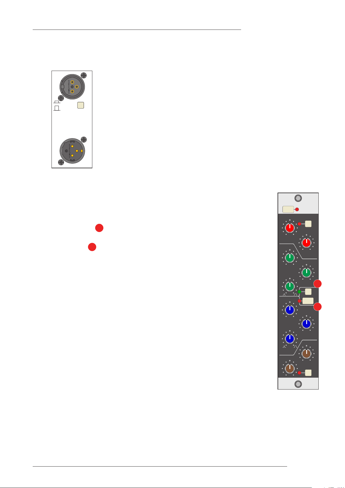
K.1 Connection
The module input and output gains can be set to operate at a nominal level of either
+4dBu or –10dBV, using a switch on the connector panel. To select the appropriate
level for the equipment you are connecting to, please check the operating manual for
your mixer or DAW. The switch should be released for +4dBu operation: push it in for
–10dBV operation.
K.2 Operation
The X-Rack E Series EQ module is a re-implementation of two of the classic SSL EQ
circuits. The module defaults to the original ‘Brown Knob’ circuit that was standard
on all early production E Series consoles but can be switched to emulate the later
‘Black Knob’ circuit.
X-Rack E Series EQ Module
The BLK button switches the module from the default ‘Brown Knob’ EQ to
1
‘Black Knob’ EQ.
The IN button switches the entire section in and out of circuit.
2
K.2.1 ‘Brown Knob’ EQ
With the BLK button out, the two parametric mid-band sections feature SSL’s classic
logarithmically symmetric design that ensures that the ±3dB up/down points retain
the same musical interval from the centre frequency regardless of frequency and
amplitude settings. The two shelving sections are traditional 6dB/octave designs
1
with an option for a fixed Q parametric response (Bell). The ‘02’ EQ, to give it its
correct name, was used on countless recordings and mixes in the early eighties.
K.2.2 ‘Black Knob’ EQ
In 1983 a new ‘242’ EQ circuit was developed in conjunction with the legendary
George Martin for the first SSL console to be installed in AIR studios. The ‘Black
Knob’ EQ, as it became known, featured enhanced cut and boost ranges (±18dB
instead of ±15dB) together with a different control law and a steeper 18dB/octave
high pass filter for tighter control of low frequencies. It is this design which is
retained today as the ‘E Series’ EQ option of the AWS 900 and Duality consoles. It is
also to be found in use in the X-Rack XR625 EQ module which features this design
alongside an implementation of the ‘G Series’ EQ.
2
Page K-1
Page 4

X-Rack Owner’s Manual
Page K-2
Page 5

X-Rack E Series EQ Module
K.3 Performance Specification
The following pages contain audio performance specification figures for the X-Rack E Series EQ Module.
o other Solid State Logic products are covered by this document and the performance of other Solid State
N
ogic products can not be inferred from the data contained herein.
L
.3.1 Measurement Conditions
K
or each set of figures on the following pages, the specific unit and test setup will be stated at the
F
beginning of that section. Any changes to the specified setup for any particular figure(s) will be detailed
eside the figures to which that difference applies.
b
K.3.2 Measurement References
Unless otherwise specified the references used in this specification are as follows:
• Reference frequency: 1kHz
• Reference level: 0dBu, where 0dBu ≈ 0.775V into any load
• Source impedance of Test Set: 50Ω
• Input impedance of Test Set: 100kΩ
• All unweighted measurements are specified as 22Hz to 22kHz band limited RMS and are expressed in
units of dBu
• All distortion measurements are specified with a 36dB/Octave low pass filter at 80kHz and are
expressed as a percentage
• The onset of clipping (for headroom measurements) should be taken as 1% THD
• Unless otherwise quoted all figures have a tolerance of ±0.5dB or 5%
• All measurements are made with the operating level switch set for +4dBu
K.3.3 Performance
Signal applied to Input and measured at Output. EQ switched In. All EQ controls set centre as appropriate.
THD + N < 0.003% at +20dBu 1kHz
< 0.003% at +20dBu 10kHz
Frequency Response ±0.5dB from 20Hz to 20kHz
–6dB at 100kHz
Output Headroom > +26dBu at onset of clipping
Noise < –80dBu (+4dBu operating level)
< –92dBu (–10dBV operating level)
Page K-3
Page 6

X-Rack Owner’s Manual
.3.4 Controls
K
This is a four band equaliser that can be switched between two different sets of curves; one based on SSL’s
‘02’ (‘Brown Knob’) EQ and the other based on the latest version of the classic ‘242’ E Series (‘Black Knob’)
EQ.
HF Band controls:
Frequency Variable from 1.5kHz to 16kHz
ain Variable between ±15dB (‘Brown’)
G
Variable between ±18dB (‘Black’)
‘Q’ (on ‘BELL’ setting) 0.8 (‘Brown’)
1.3 (‘Black’)
HMF Band controls:
Frequency Variable from 600Hz to 7kHz
Gain Variable between ±15dB (‘Brown’)
Variable between ±18dB (‘Black’)
‘Q’ Variable from 0.5 to 2.5 (‘Brown’)
Variable from 0.5 to 4 (‘Black’)
LMF Band controls:
Frequency Variable from 200Hz to 2.5kHz
Gain Variable between ±15dB (‘Brown’)
Variable between ±18dB (‘Black’)
‘Q’ Variable from 0.5 to 2.5 (‘Brown’)
Variable from 0.5 to 4 (‘Black’)
LF Band controls:
Frequency Variable from 30Hz to 450Hz
Gain Variable between ±15dB (‘Brown’)
Variable between ±18dB (‘Black’)
‘Q’ (on ‘BELL’ setting) 0.8 (‘Brown’)
1.3 (‘Black’)
Page K-4
Page 7

X-Rack E Series EQ Module
K.4 Calibration Information
The X-Rack E Series EQ module is factory calibrated and should only need calibration if a potentiometer
r other component has been replaced or if it is suspected that there is a problem with calibration.
o
In each of the following instructions it is assumed that the lid of the X-Rack has been removed and that
power has been applied. It is also assumed that unless otherwise specified, all switches are released and
all front panel potentiometers are at unity or minimum position as appropriate. The required accuracy for
each adjustment will be specified along with the target value. All level and distortion measurements
should be made with audio-band 20Hz to 20kHz filters unless otherwise specified.
ll presets are accessible from the top of the unit.
A
Note. The unit should be allowed to warm up with power applied for at least 15 minutes prior to making any adjustments.
K.4.1 EQ Alignment
Equipment Required: Calibrated audio oscillator and audio level meter
Test Signal: Sine wave @ 0dBu, frequencies as specified below
Input and Output: Oscillator to Input, Output to the audio level meter
Unit Setup: 1. Switch the EQ IN and release all other EQ switches.
2. Release the +4dBu/–10dBV switch on the rear panel.
3. Set all of the Q and Frequency controls fully anti-clockwise and all Gain
controls to their centre indent.
HF EQ – Maximum Gain
Adjustment: 1. Ensure that the BLK switch is released.
2. Set HF Gain to maximum and select HF BELL. Set the audio oscillator for
12kHz and adjust HF Frequency to find the maximum level on the audio
level meter.
3. Adjust VR11 for +15dBu ±0.25dB.
4. Switch BLK in and re-adjust HF Frequency for maximum level.
5. Adjust VR12 for +18dBu ±0.25dB.
6. Reset HF Gain to its centre indent position, de-select HF BELL and release
the BLK switch. Re-check the audio level meter for 0dBu.
HMF EQ – Maximum Gain
Adjustment: 1. Ensure that the BLK switch is released.
2. Set HMF Gain to maximum and HMF Q fully anti-clockwise. Set the
audio oscillator for 3kHz and adjust HMF Frequency to find the
maximum level on the audio level meter.
3. Adjust VR13 for +15dBu ±0.25dB.
4. Switch BLK in and re-adjust HMF Frequency for maximum level.
5. Adjust VR14 for +18dBu ±0.25dB.
6. Reset HMF Gain to its centre indent position and release the BLK switch.
Re-check the audio level meter for 0dBu.
LMF EQ – Maximum Gain
Adjustment: 1. Ensure that the BLK switch is released.
2. Set LMF Gain to maximum and LMF Q fully anti-clockwise. Set the audio
oscillator for 1kHz and adjust LMF Frequency to find the maximum level
on the audio level meter.
3. Adjust VR15 for +15dBu ±0.25dB.
(continued)
Page K-5
Page 8

X-Rack Owner’s Manual
5K01**
5K01**
2
3
1
2
3
1
0V
+
–
0V
+
–
To measuring
equipment
From unit
under test
1
2
1
Resistor tolerance should ideally be 0.01%
Absolute level measured will depend upon the input
impedence of the measuring equipment.
1.
2.
Note
. Switch BLK in and re-adjust LMF Frequency for maximum level.
4
5. Adjust VR16 for +18dBu ±0.25dB.
6. Reset LMF Gain to its centre indent position and release the BLK switch.
Re-check the audio level meter for 0dBu.
LF EQ – Maximum Gain
Adjustment: 1. Ensure that the BLK switch is released.
2. Set LF Gain to maximum and select LF BELL. Set the audio oscillator for
0Hz and adjust LF Frequency to find the maximum level on the audio
8
level meter.
3. Adjust VR17 for +15dBu ±0.25dB.
4. Switch BLK in and re-adjust LF Frequency for maximum level.
5. Adjust VR18 for +18dBu ±0.25dB.
6. Reset LF Gain to its centre indent position, release the BLK switch and deselect LF BELL. Re-check the audio level meter for 0dBu.
K.4.2 Output Balance
Equipment Required: Calibrated audio oscillator, audio level meter and a ‘balance’ adaptor (see
below).
Test Signal: 1kHz sine wave at +24dBu.
Input and Output: Oscillator to the Input of the channel being tested, Output to the level
meter via the ‘balance’ adaptor.
Unit Setup: Ensure that all front panel switches are off and all controls are set fully
anti-clockwise.
Adjustment: Connect the test equipment to the each channel in turn and adjust VR19
(BAL) for minimum level (< 55dBr).
K.4.3 ‘Balance’ Adaptor
For the output balance adjustment, a ‘balance’
adaptor such as that illustrated here will be
required. This adaptor consists of a pair of
close tolerance resistors in an in-line cable and
is used to sum together a balanced output in
order to correctly adjust the level balance of the
measured output; perfect balance should result
in complete signal cancellation.
Page K-6
Page 9

K.5 Connector Details
X-Rack E Series EQ Module
Audio Input
Location: Rear Panel
Conn’ Type: XLR Female
in
P
1 Chassis
2 Audio +ve
3 Audio –ve
escription
D
Audio Output
Location: Rear Panel
Conn’ Type: XLR Male
in
P
1 Chassis
2 Audio +ve
3 Audio –ve
escription
D
K.6 Physical Specification
Depth: 200mm / 7.9 inches including front panel knobs, excluding connectors
275mm / 10.9 inches including front panel knobs and connectors
Height: 171mm / 6.75 inches
Width: 35mm / 1.4 inches front/rear panels
49mm / 1.9 inches overall width (front and rear panels are offset)
Weight: 260g / 9.5 ounces
Boxed size: 190mm x 290mm x 70mm / 7.5" x 11.5" x 2.5"
Boxed weight: 460g / 16.5 ounces
* All values are approximate
K.7 Environmental Specification
As per X-Rack – see page 19.
Page K-7
Page 10

X-Rack Owner’s Manual
Page K-8
 Loading...