

Page 1

www.solidstatelogic.com
Duende Native
User Guide
Duende Native. This is SSL.
Page 2

Document History
December 2010 82BDNM01A Initial Release
Page 3

Table of Contents
IInnttrroodduuccttiioonn 11
elcome to the World of SSL
W
About This Manual 1
Plug-in Tutorials and Support 1
About the SSL plug-in range 2
Channel Strip 2
tereo Bus Compressor
S
X-Comp 3
X-EQ 4
Vocalstrip 5
Drumstrip 6
X-Verb 7
11.. SSooffttwwaarree SSeettuupp 99
Overview 9
System Requirements 10
Windows 10
Macintosh 10
Host Applications 10
Downloading the Software 11
Problems Downloading? 11
Installing the Software (Macintosh) 12
Installing the Software (Windows) 13
Creating an SSL Profile 14
Logging into the SSL website 14
Buying Plug-ins 15
Applying Activation Codes to your Profile 16
CD Activation Codes 16
Free Demo Activation Codes 16
Activating Plug-ins 17
1
2
22.. EEQQ && DDyynnaammiiccss CChhaannnneell SSttrriipp 1199
Introduction 19
Interface Techniques 20
Automation 20
Input Section 20
Filter Section 20
Equaliser Section 21
Dynamics Section 22
Compressor/Limiter 22
Expander/Gate 22
Dynamics Values 23
Side Chain Processing Order 23
Channel Processing Order 23
Output Section 23
Page 4

33.. SStteerreeoo BBuuss CCoommpprreessssoorr 2255
Introduction 25
nterface Techniques
I
Control Parameters 25
2
44.. XX--CCoommpp 2277
ntroduction
I
Interface Techniques 27
utomation
A
Control Parameters 28
Plug-in Bypass 28
Presets 28
A-B comparisons 28
Knee 28
Max GR 28
Bleed 29
Auditioning Bleed Bands 29
Compressor Values 29
Input and Output Sections 30
Compression Law Graph 30
Bleed Graph 30
I/O Diff Graph 30
GR History 30
Colour of knobs 30
2
2
5
7
7
55.. XX--EEQQ 3311
Introduction 31
Interface Overview 31
EQ Graph Display 31
Input and Output Sections 32
Interface Techniques 32
Automation 32
EQ Configuration 33
Plug-in Bypass 33
Presets 33
A-B comparisons 33
Analyse 33
Parallel 34
EQ Parameter Values 34
EQ and Filter Shapes 35
Bell Shapes 35
Shelving Bands 36
Filter Shapes 36
EQ History 37
An Audio Engineer’s Best Friend 37
The Best of the Analogue and Digital Worlds 37
Analogue Parametric EQ Modelling 37
Page 5

Non Linear-phase EQ 38
Parallel Passive EQ 38
66.. VVooccaallssttrriipp 3399
Introduction 39
Interface Overview 39
lug-in Bypass
P
Presets 40
-B Comparisons
A
Automation 40
Input and Output Sections 40
Vocalstrip Modules 40
De-esser 40
De-ploser 41
Equaliser 41
Compander 42
Processing Order 42
3
4
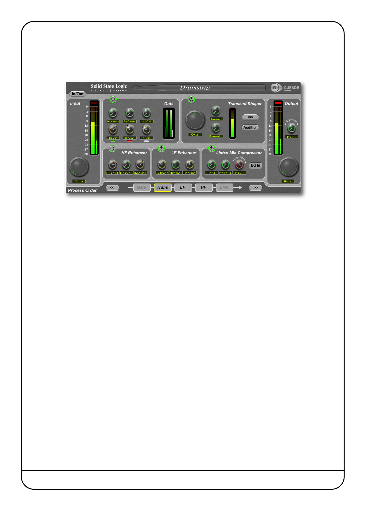
77.. DDrruummssttrriipp 4433
Introduction 43
Interface Overview 43
Plug-in Bypass 43
Automation 43
Input and Output Sections 44
Drumstrip Modules 44
Gate 44
Transient Shaper 45
HF and LF Enhancers 46
Listen Mic Compressor 46
Processing Order 46
9
0
88.. XX--VVeerrbb 4477
Interface Overview 47
Plug-in Bypass 47
Automation 47
Presets 48
A-B Comparisons and Morphing 48
The Graph Display 48
Input and Output Levels 49
Mix Levels 49
Image Control 50
X-Verb Configuration 51
Kill Tail Button 51
1. Select an Algorithm or Preset. 51
2. Adjust the Primary Parameters 52
3. Adjust the Detail Parameters 53
Detail Parameter Ranges and Descriptions 56
ER Menu 56
Page 6

REV Menu 57
AAppppeennddiixx:: CCrroossss--ggrraaddee 5599
ross-grade Eligibility Conditions
C
Additional Conditions 59
Who Gets What? 59
here is the Catch?
W
FAQs 60
uende Native Cross-grade Installation
D
5
6
6
9
0
1
Page 7

Introduction
WELCOME TO THE WORLD OF SSL
Congratulations on purchasing SSL’s Duende Native plug-ins. Duende Native delivers a taste of the SSL mix experience –
powerful channel and dynamics processing, the legendary Stereo Bus Compressor, plus a variety of contemporary audio
tools developed by SSL to provide you with extensive processing versatility.
SSL is a company that has built its considerable reputation on excellence in audio production. With the rise in popularity of
DAWs, there was an increasing demand to bring SSL’s values and sonic signature to the world of plug-ins. Duende was our
response to that demand. Duende was the result of our unique understanding of SSL’s sonic heritage coupled with years of
DSP development in SSL's digital console range.
Initially to bring Duende to life, we took the DSP heart of our acclaimed C-Series consoles and transplanted it into a hardware
plug-in host. As native processing has become faster, the ability to run the sophisticated Duende plug-in algorithms efficiently
in the host CPU has removed the need for additional DSP, while still leaving the DAW to deliver smooth workflow. Duende
Native plug-ins deliver the same acclaimed sonic performance as their hardware DSP predecessors, but also offer the
convenience and reliability of a complete ‘in the box’ solution.
Duende is a term used in flamenco connected to magic, spirit and passion, it’s a name that evokes all that we've achieved
with this product – and all we hope it will inspire its users to achieve.
ABOUT THIS MANUAL
This manual starts with a complete overview of the processes involved in installing and authorising your plug-ins then going
on to a detailed description of all seven of the plug-ins in the Duende Native range.
Please note that the procedures involved in using plug-ins within your host application are not covered in this manual. Please
refer to your host application’s user guide for more information on how to use plug-ins in general.
If you are reading this on-screen, you will find that a number of helpful hyperlinks have been included, providing easy
navigation around the manual, as well as quick access to key parts of the SSL website.
PLUG-IN TUTORIALS AND SUPPORT
If you would like any advice or support about your SSL plug-ins, the SSL website has an extensive support FAQ section:
www.solidstatelogic.com/support
SSL have created a number of tutorials which provide plug-in users with clear explanations and expert advice
on signal processing techniques. They include Pro Tools, Logic and Cubase/Nuendo project files which allow
you to experience real-life examples of the techniques within the Duende plug-ins. These are located within
the Duende Product section of the SSL website:
www.solidstatelogic.com/music/duende native/tutorials.asp
You can access these tutorials by clicking the Tutorial icon on the right – these icons are also found throughout the manual.
?
click here for
on-line
tutorials
Duende Native User Guide Page 1
Page 8
ABOUT THE SSL PLUG-IN RANGE
Channel Strip
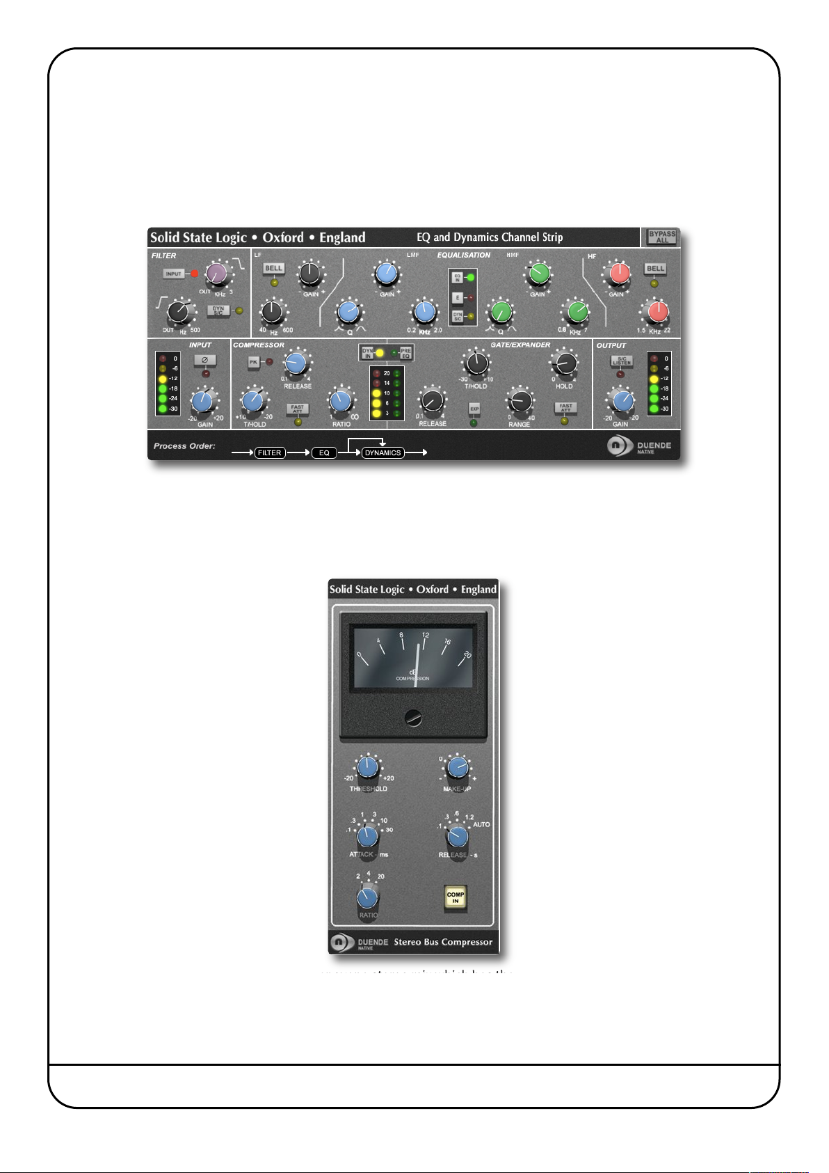
The EQ and Dynamics Channel Strip plug-in is based on the EQ and compressor sections of the XL 9000 K Series console. SSL
were the first mixing console manufacturer to feature dynamics and EQ on every channel on an in-line console with the
SL 4000 B Series in 1977. The plug-in includes separate high and low pass filters, an independent compressor/limiter and
gate/expander, a four band parametric equalizer which is assignable to the dynamics sidechain, variable processing order
as well as input and output gain adjustment and phase inversion.
Stereo Bus Compressor
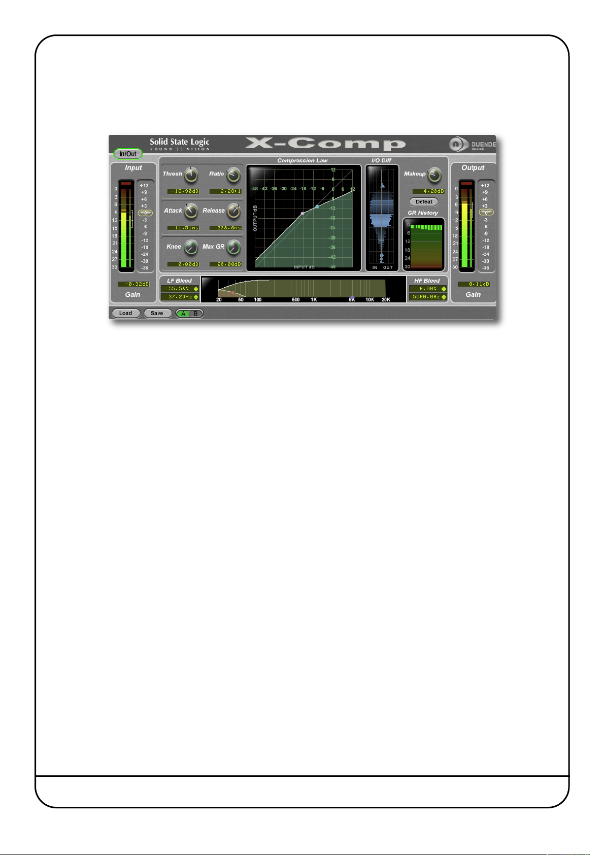
The Stereo Bus Compressor plug-in is a stereo version of the legendary centre section stereo bus compressor found on the
XL 9000 K Series console. It provides high quality stereo compression, giving you critical control over the dynamic range of
audio signals.
Uses may include inserting the bus compressor over a stereo mix which has the effect of ‘gluing’ the mix together whilst still
maintaining a big sound. The dynamics of drum overheads or whole drum kits can be controlled very effectively with the bus
compressor. As it is available as either a stereo or mono plug-in the bus compressor can be used for practically any application
that requires superior compression.
Page 2 Duende Native User Guide
Page 9
-Comp
X
-Comp can deliver the transparent audio finesse of a mastering grade stereo compressor or be driven to inject character and
X
aw power to rival the SSL Listen Mic Compressor. In X-Comp we haven’t just modelled a particular compressor, but have
r
rovided a set of features and controls that allow the emulation of many vintage and modern compression designs based on
p
well loved SSL feed forward compressor algorithm.
a
Key Features
• Dual symmetrical knee design allows detailed shaping of the compression characteristic
• Advanced side chain architecture using 1st order filters delivers user friendly Frequency Dependant Parallel Compression
• Amplitude Histogram and Gain Reduction history displays provide advanced real time pre/post signal analysis
• Max Gain Reduction control provides genuine vintage compressor characteristics
• Intuitive user interface with drag and move graphic, mouse wheel and numeric editing
• A/B facility for instant comparison of two different compression set ups
• Proprietary preset management functions providing compatibility between all DAW platforms
• Global latency free bypass
• Superb mastering grade audio quality delivered by Duende’s 64-bit floating point engine
• Preset library based on settings used by some of the worlds top mixing engineers
Duende Native User Guide Page 3
Page 10
-EQ
X
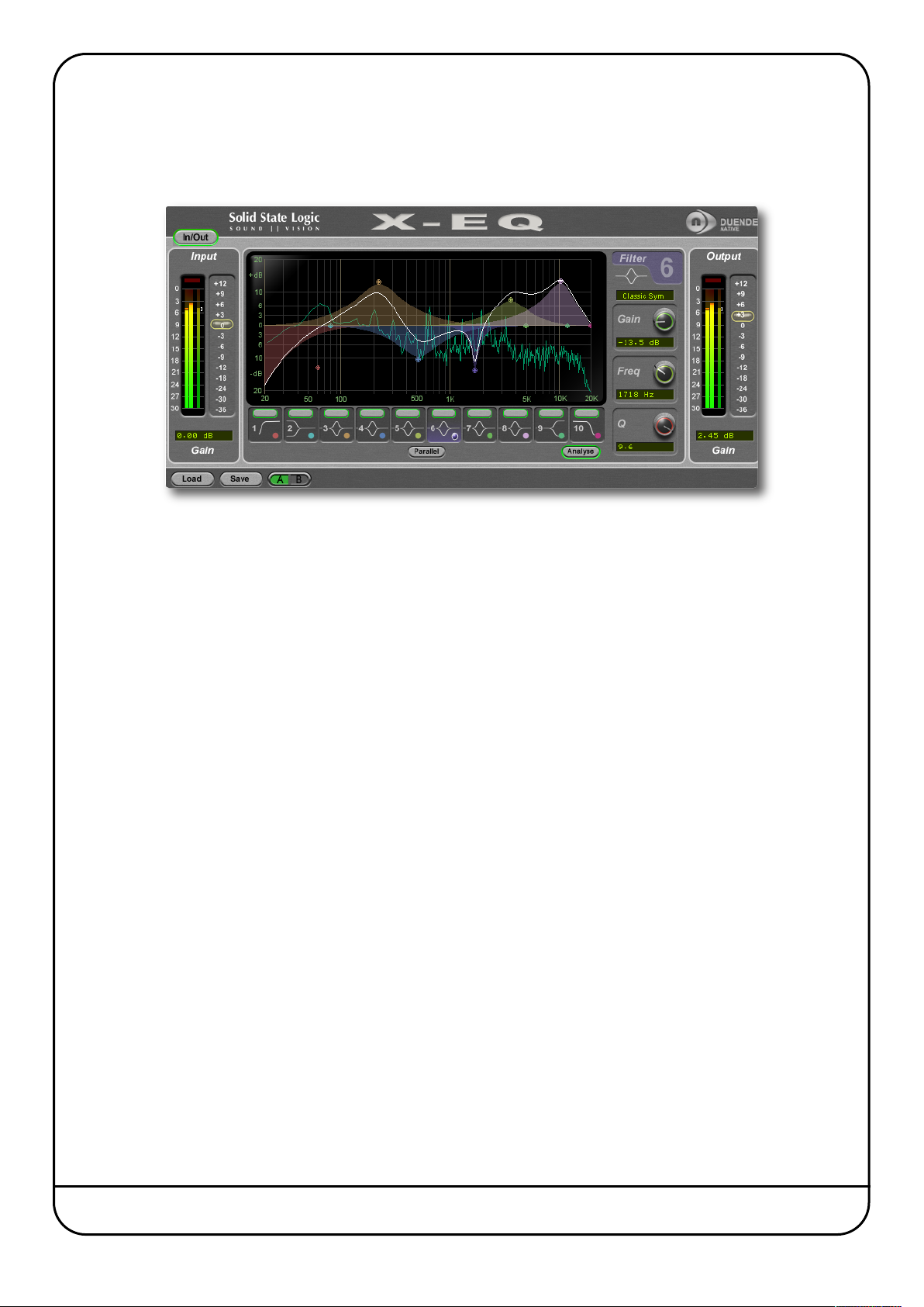
-EQ is a versatile and comprehensive mastering grade parametric EQ plug-in built from the ground up for Duende. It has an
X
nprecedented clarity, smoothness, and excellent high-frequency response. A total of 10 EQ bands are provided, split into
u
edicated HP and LP filters, LF and HF shelves and 6 bell bands. A Parallel EQ mode is also provided which recreates the
d
haracteristic sound of an old parallel passive PEQ circuit built with inductors and capacitors.
c
Key Features
• 10 band fully parametric high quality digital EQ
• A total of 16 different filter types: 5 different cut filters, 9 bell shapes, shelving filters and a parallel mode
• Extensive control options including dragable EQ graph nodes, mouse wheel adjustment and numerical data entry
• Extremely low noise and low non-linear distortion filter algorithms resulting in the residual THD+N significantly lower
than 24-bit quantisation noise
• Comprehensive stereo/mono peak (with clip-hold), RMS and dynamic history metering at input and output
• Different bell filter types are all normalised to look identical at +6dB boost allowing for quick comparison between filter
types
• Proprietary preset management functions providing compatibility between all major DAW platforms
• A/B functionality for easy comparison of any two settings
• Individual band bypass
• Global latency free bypass
• Real-time FFT Analyser showing the result of the EQ processing on the audio spectrum
• Superb mastering grade audio quality delivered by Duende’s 64-bit floating point engine
• Preset library based on settings used by some of the worlds top mixing engineers
Page 4 Duende Native User Guide
Page 11
ocalstrip
V
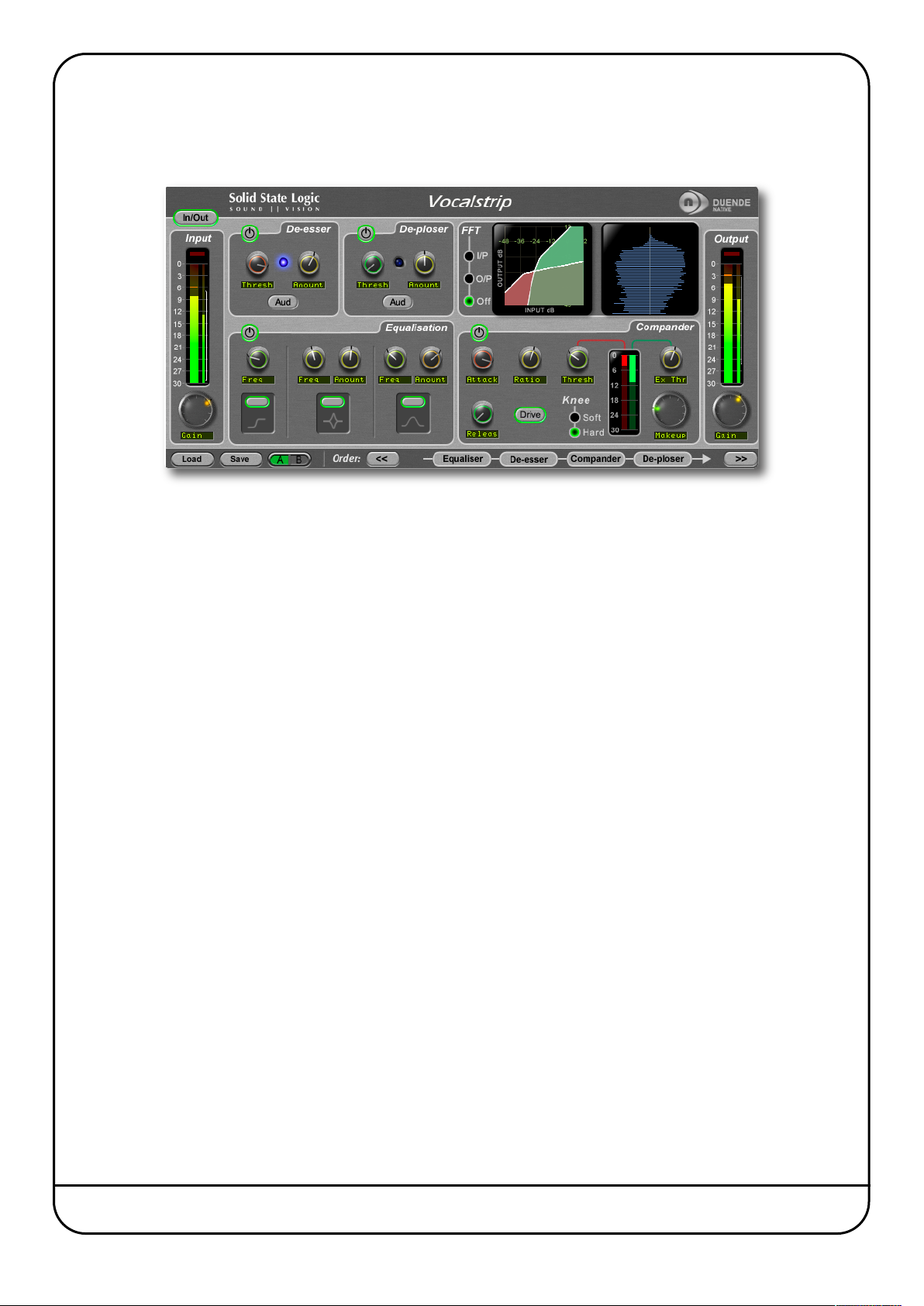
ocalstrip is a one stop solution for superior vocal processing, with all the tools you need to take your vocal sound into the
V
ajor league. Vocalstrip features 4 configurable processing blocks to take care of unwanted artefacts, dynamics and
m
qualisation and extensive metering and visual feedback give you invaluable information during your work.
e
Key Features
• Intelligent De-esser
• Intelligent De-ploser
• 3 band EQ
• Compander featuring compression, downwards expansion and output drive
• Extensive visual feedback including a real-time FFT analyser showing the result of the EQ processing on the audio
spectrum
• Complete control over process order
• Extensive control options including mouse wheel adjustment and numerical data entry
• Proprietary preset management functions providing compatibility between all DAW platforms
• A/B functionality for easy comparison of any two settings
• Global latency free bypass
• Superb mastering grade audio quality delivered by Duende’s 64-bit floating point engine
• Preset library based on settings used by some of the worlds top mixing engineers
Duende Native User Guide Page 5
Page 12
rumstrip
D
he Drumstrip plug-in for Duende brings a unique blend of tools to the Duende Native platform, which provides an
T
nprecedented amount of control over the transient and spectral elements of drum and percussion tracks. Manipulation
u
hich previously may have been time-consuming or impossible with traditional EQ and dynamics processing becomes elegant
w
nd rewarding with SSL Drumstrip.
a
Key Features
• Transient shaper capable of drastically changing the attack characteristics of rhythmic tracks. An audition mode makes
for easy setup
• Highly controllable Gate featuring both open and close thresholds, attack, hold, release and range control
• SSL Listen Mic Compressor – as featured in the LMC-1 plug-in – with extra functionality
• Separate high and low frequency enhancers provide spectral control not achievable with traditional EQ
• Peak and RMS metering on both input and output
• Wet/dry controls on both the main output and the LMC, allow parallel processing to be easily dialled in
• Process order control over all five sections gives complete flexibility over the serial signal chain
• Latency-free bypass of all processing
Page 6 Duende Native User Guide
Page 13
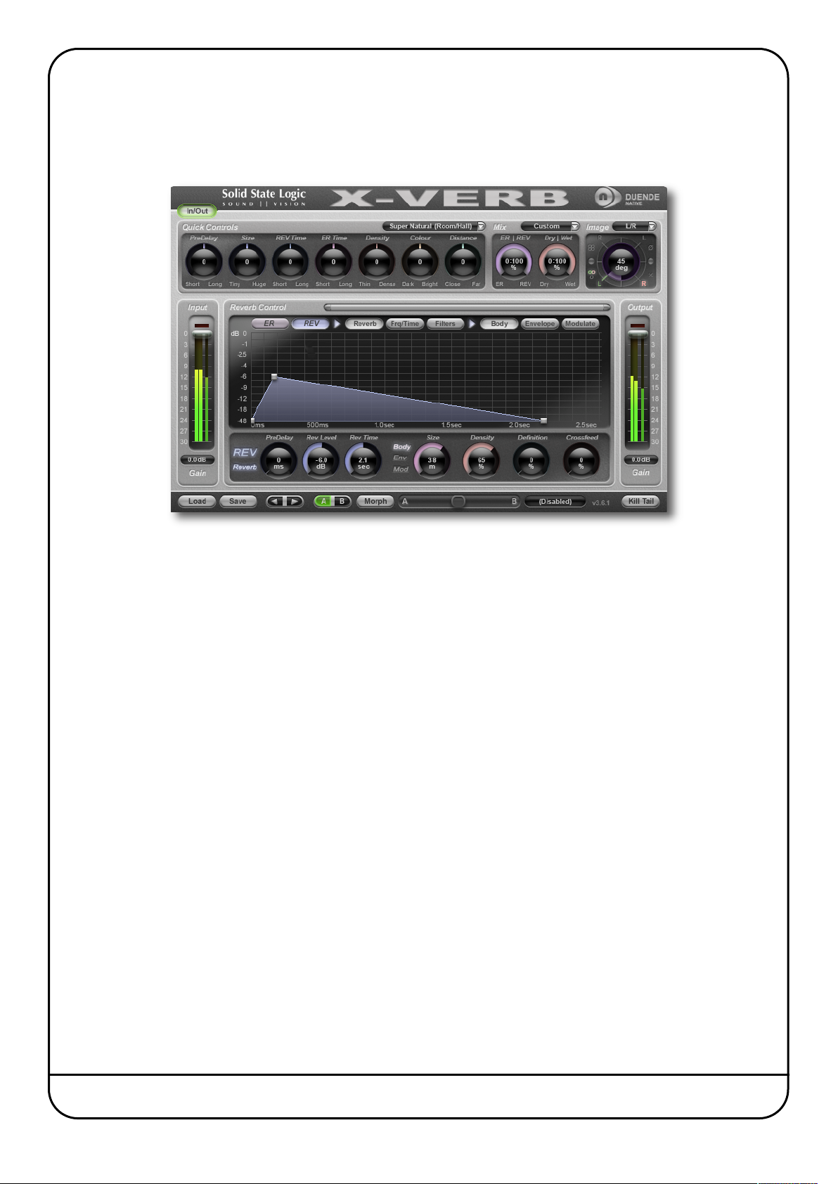
-Verb
X
-Verb is a versatile and comprehensive studio grade reverberation plug-in, delivering the density, warmth, depth and
X
tunning detail usually only associated with high class hardware reverb units. The use of innovative Diffusion Engines and
s
nnovative processing design provides superior performance that surpasses other Reverb Plug-Ins in both artistic freedom,
i
epth and sonic quality. This plug-in may well provide all the different Reverb options you will ever need.
d
Key Features
• Unique and modular SSL HiD Reverb Algorithm Engine
• 4 Core Algorithms create a complete collection of processors
• Quick Controls panel to easily alter the superb Presets
• Stunning Graphical User Interface to access the detailed parameter set
• Automatable Morphing feature to dynamically morph from one preset to another
Duende Native User Guide Page 7
Page 14

Blank page – well, nearly.
Page 8 Duende Native User Guide
Page 15
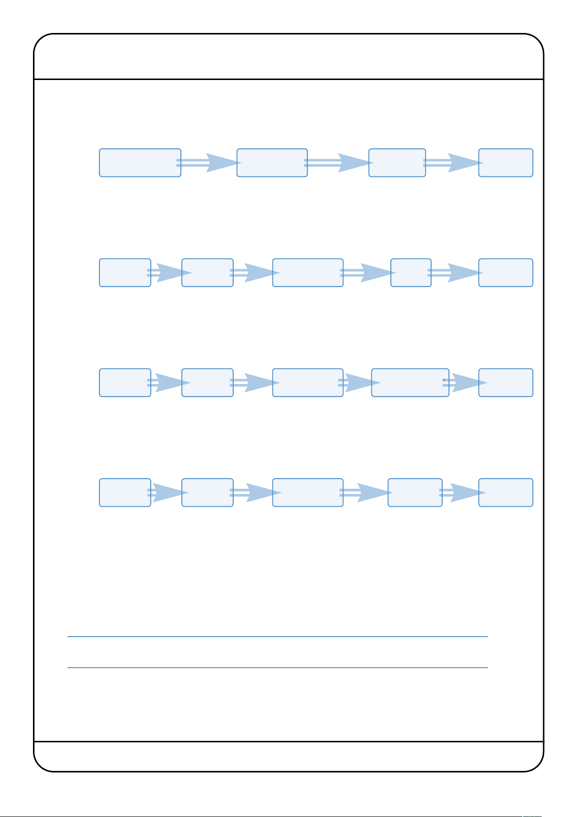
1. Software Setup
OVERVIEW
In order to get your SSL software working, here are the steps you will need to go through:
With a CD
Without
a CD
Free Demo
Install the software
from the CD
Download
the software
Download
the software
Install
the software
Install
the software
Create an SSL
Profile and log in
Create an SSL
Profile and log in
Create an SSL
Profile and log in
Apply Licence
to your Profile
Buy your
plug-ins
Apply demo licence
to your Profile
Activate your
plug-ins
Activate your
plug-ins
Activate your
plug-ins
Duende
Cross-grade
Download
the software
Install
the software
Log into your
SSL Profile
Cross-grade
your plug-ins
Re-activate
your plug-ins
Each of these steps will be covered over the following pages. There is a good chance that you are already some way through
this process – feel free to jump to the appropriate section.
You can navigate to any of the sections by clicking on the appropriate blue box. If you would like more information on any
stage of the setup process, please refer to the Duende Native area of the SSL website.
Cross-grade: This option is for users who already have a Duende unit and wish to take advantage of the
free cross-grade offer. Please see the Appendix for details, terms and conditions.
Duende Native User Guide Page 9
Page 16

SYSTEM REQUIREMENTS
efore starting the process, you may want to confirm that no upgrades to your computer or its software are required to run
B
uende Native:
D
Windows
- Windows XP, Vista or 7 (32- or 64-bit versions)
- Intel Core2 (or comparable) CPU running at 2GHz or higher
- 2GB of RAM minimum
Duende Native does not support Pentium or Celeron CPUs
Macintosh
- Intel Macintosh running at 1.83 GHz or higher
- OSX 10.5.8 or higher
- 2GB of RAM minimum
Duende Native does not support Power PC Macintosh.
Host Applications
Duende Native is designed to run within the following host applications:
- SSL Soundscape v6
- Steinberg Cubase v5.5
- Steinberg Nuendo v5
- Apple Logic v9
- Pro Tools v8
- Ableton Live v8.1
- Sonar v8
- Reaper v3
- Studio One
Duende Native has been tested in the above applications and is compatible. However, it will work with
virtually any VST/AU host, including those which have not been tested. Please refer to the Duende Native
FAQs for updated compatibility information.
Page 10 Duende Native User Guide
Page 17
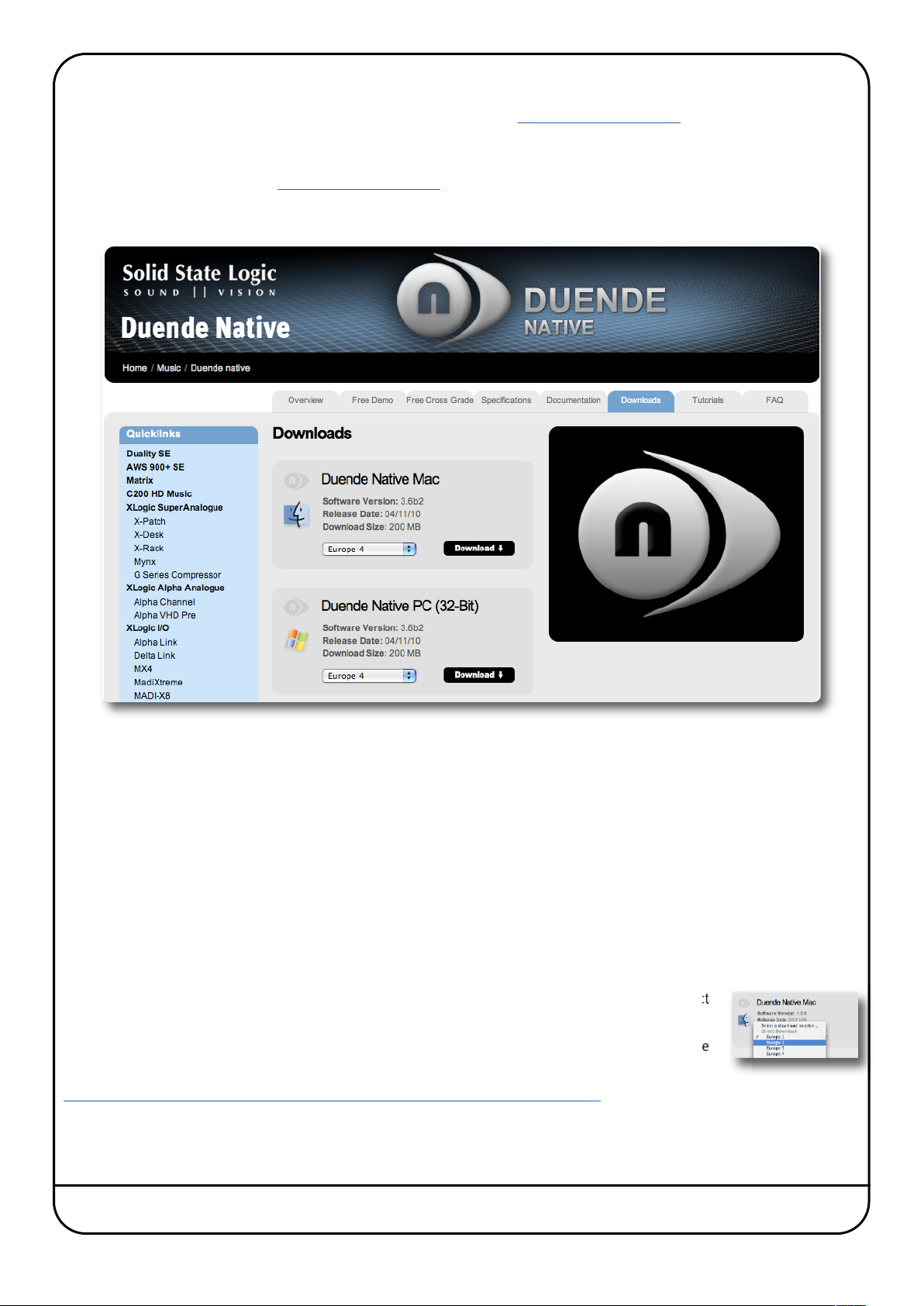
DOWNLOADING THE SOFTWARE
f you do not have a Duende CD, you can download the software from www.solidstatelogic.com. Note that you do not need
I
o buy plug-ins to download , though you will need to register on the SSL website before you can use them. To use them for
t
ore than one month, you will need to buy authorisation, as described on Page 19.
m
To download the software, go to www.solidstatelogic.com
by the MUSIC entry in the drop-down which appears, and click on Duende Native in the second drop-down which appears.
Select the Downloads tab to be taken to the page shown below. Alternatively, just click on the page displayed here in the pdf:
, hover over the PRODUCTS tab (at the top of the page) followed
There are three download boxes, for Macintosh, 32-bit Windows machines and 64-bit Windows machines. Click on the
Download label within the appropriate download box, and the download will start automatically.
It is important that Windows users install the correct software version – please refer to your PC’s User Guide to establish
which of the following host/OS permutations applies to you:
32-bit Windows, 32-bit Host: 32-bit installer required (the 64-bit installer will not run on 32-bit Windows);
64-bit Windows, 32-bit Host: 32-bit installer required (the installer detects that Windows is 64-bit and installs 64-bit
CodeMeter, but installs 32-bit plug-ins – see next page for more explanation);
64-bit Windows, 64-bit Host: 64-bit installer required;
64-bit Windows, Separate 32-bit and 64-bit Hosts: both installers required!
Problems Downloading?
If the download is very slow, click on the drop-down box at the bottom of the download box, and select
a different location number (1, 2, 3 or 4) within your geographical area (see right).
If the download doesn’t work, check that your computer meets the system requirements on the
following page, and check that you have downloaded the correct version.
Note that the SSL website has a support FAQ section. Click here to be taken there…
Duende Native User Guide Page 11
Page 18
INSTALLING THE SOFTWARE (MACINTOSH)
nstallation on Macintosh requires that CodeMeter be installed before Duende Native. Locate the Duende Native installer.
I
• If you have a Duende Native CD, both installers will be found on the CD.
• If you have downloaded Duende Native from the SSL Website, the installers will both be contained within the Duende
Native disk image file that you downloaded; double click this file to mount the disk image.
Run the CodeMeter Installer by double-clicking the CodeMeter Runtime package. Follow the instructions within
the installer. You will then need to restart your computer.
Once your computer has restarted, open once again either the CD or the disk image file and locate
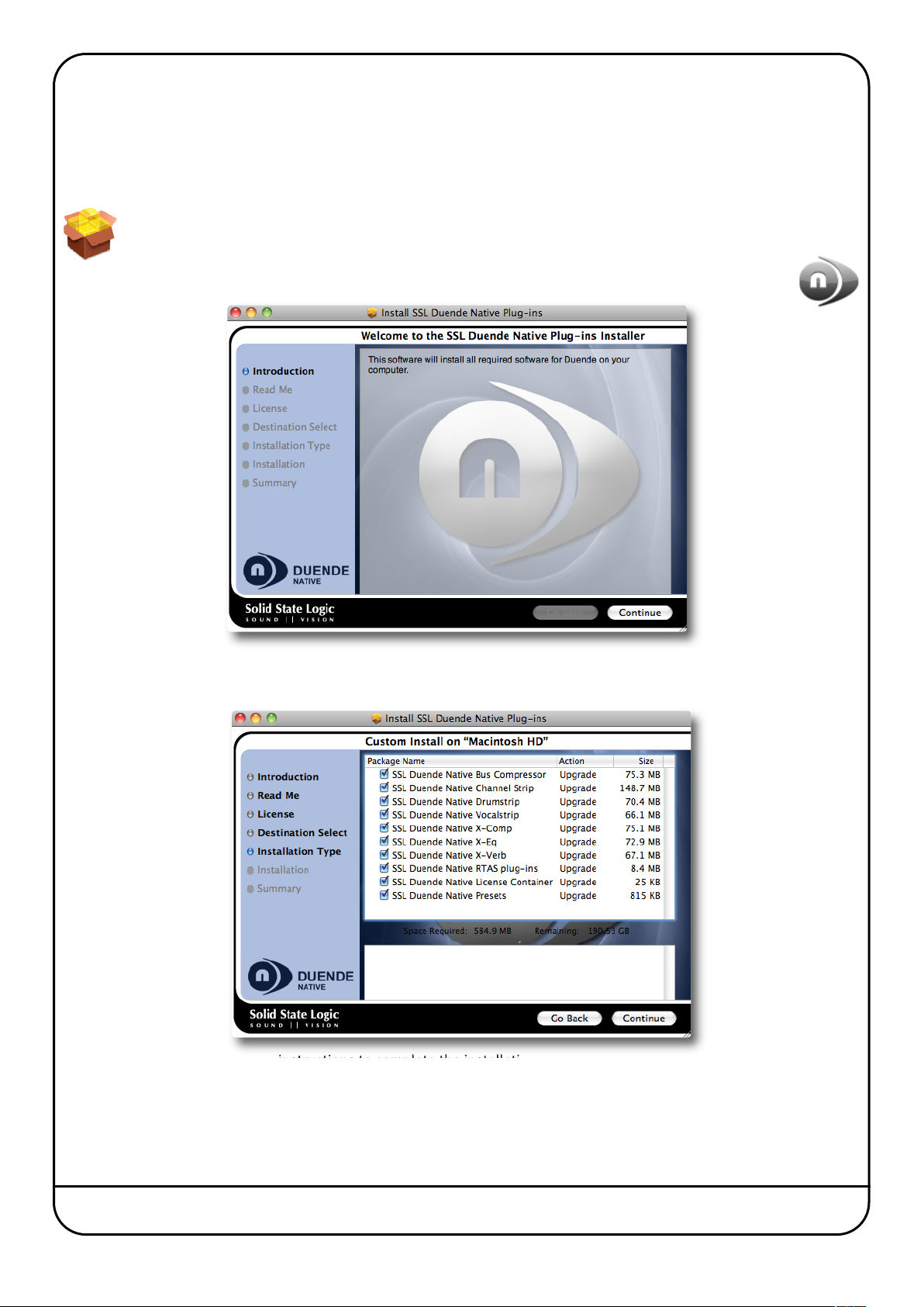
the Duende Native Plug-ins package. Double-click this package to run the installer:
You will be taken through a number of screens, eventually reaching one which lists the Duende Native plug-ins. Uncheck any
of them which you do not wish to install:
Continue to follow the on-screen instructions to complete the installation.
Page 12 Duende Native User Guide
Page 19
INSTALLING THE SOFTWARE (WINDOWS)
ocate the Duende Native installer, either on the Duende Native Installer CD, or in your computer’s downloads
L
older. The installer application is named Duende Native Setup 32-bit for 32-bit Digital Audio Workstations, or
f
uende Native Setup 64-bit for 64-bit Digital Audio Workstations.
D
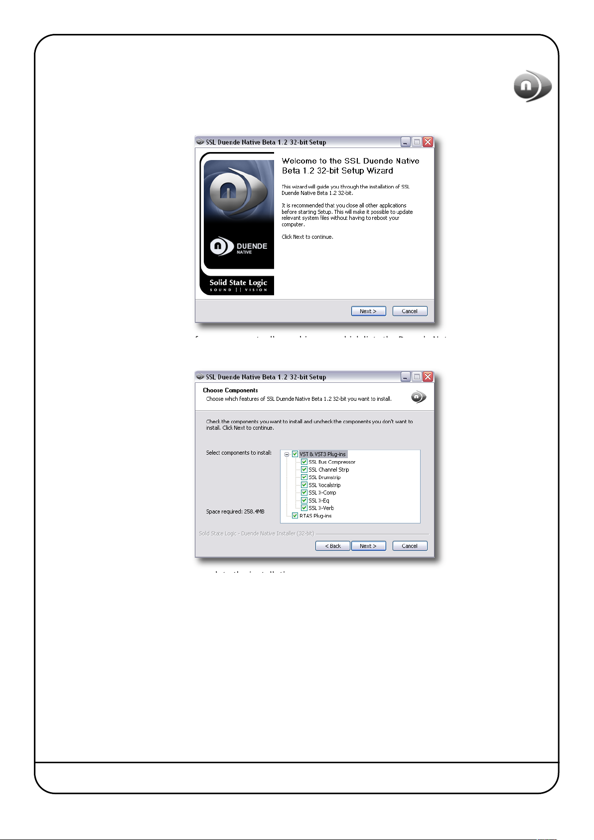
Double-click on the icon, and an installer window will open:
You will be taken through a number of screens, eventually reaching one which lists the Duende Native plug-ins. Uncheck any
of them which you do not wish to install:
Follow the on-screen instructions to complete the installation.
Duende Native User Guide Page 13
Page 20
CREATING AN SSL PROFILE
n order to authorise your SSL software, you need to create an SSL profile:
I
Go to www.solidstatelogic.com
on the picture below will take you there:
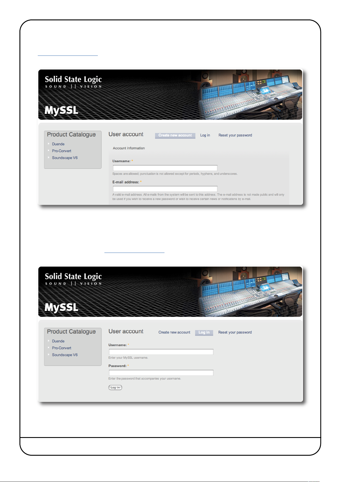
Fill in your details and click on the Create New Account button at the bottom of the page.
and click on REGISTER, located in the top right-hand corner of the SSL home page. Clicking
You will be sent a password by email. Once you have received this email, you are ready to continue.
LOGGING INTO THE SSL WEBSITE
To log into the SSL website, go to www.solidstatelogic.com and click on LOG IN in the top right-hand corner. Clicking on the
picture below will take you there:
Type your username you created and the password sent to you by email, and click on the Log in button below the password.
Page 14 Duende Native User Guide
Page 21
BUYING PLUG-INS
ou must have an SSL profile and be logged into the SSL website to buy plug-ins. Please refer to the previous page for
Y
nformation about creating and logging into a profile.
i
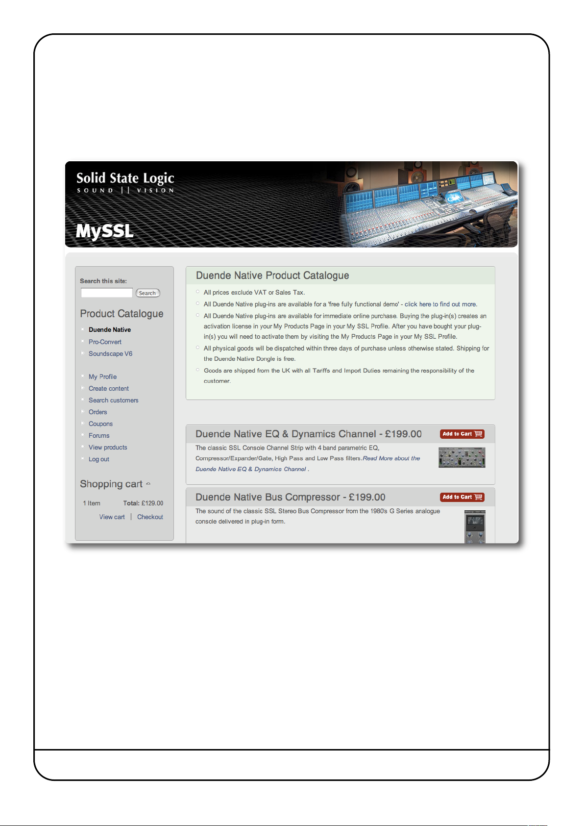
When you log into the website, you are automatically taken to the MySSL area. To navigate there from elsewhere in the
website, click on your name in the top right-hand corner of the screen.
In the Product Catalogue down the left-hand side of the MySSL area, click on Duende Native to be taken to the Duende
Native store:
Select the plug-ins you wish to purchase by clicking on their Add to Cart buttons and complete the check-out and purchase
processes. You will automatically be taken to the My Products section of MySSL to activate your plug-ins.
Duende Native User Guide Page 15
Page 22
APPLYING ACTIVATION CODES TO YOUR PROFILE
CD Activation Codes
If you bought your plug-ins on CD, you must apply your activation codes to your profile before you can activate them. To do
this, log into your profile then go to www.solidstatelogic.com/duendenativepacks and follow the on-screen instructions.
To locate your activation code, open your CD sleeve and you will find it on a sticker on the left-hand panel. It is 18 to 20
characters long, in the format: XXXXX–XXXXX–XXX–XXXXX (note that the third set of digits may be three, four or five digits).
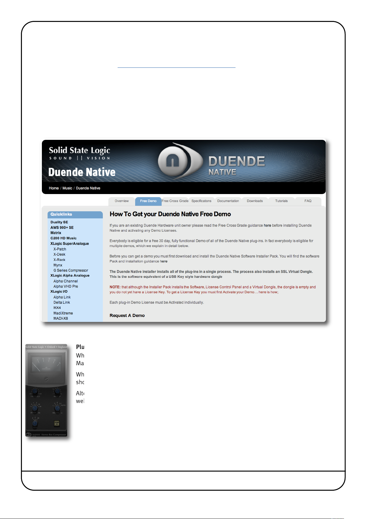
Free Demo Activation Codes
Before you can activate any free demos you have downloaded, you need to apply them to your SSL Profile. To do this, log
into the SSL website, as described on Page 18. Then hover over the PRODUCTS tab (at the top of the page) followed by the
MUSIC entry in the drop-down which appears, and click on Duende Native in the second drop-down which appears. Select
the Free Demo tab to be taken to the page shown below. Alternatively, just click on the page displayed here in the pdf:
Read the on-screen instructions and click on the I Want A Demo button. This will send free demo licences to your Profile.
Plug-in Expiration
When your plug-in demo period comes to an end, the plug-in will stop working. When this occurs on
Macintosh the plug-in will appear glassed over – as shown left for the Stereo Bus Compressor.
When this happens, you will be eligible for another 7 day free demo after 30 days. Go to the web page
shown above for full details of further free demo licences.
Alternatively, you can re-activate your plug-ins permanently by going to the MySSL area of the SSL
website and purchasing full licences, as described on the previous and following pages.
Page 16 Duende Native User Guide
Page 23
ACTIVATING PLUG-INS
ote that if you have purchased your plug-ins on CD or are using a free demo, you will need to apply activation codes to your
N
rofile before activating them, as described on the previous page.
p
You must be logged into your Profile on the SSL website to authorise your plug-ins. Please refer to Page 18 for information
about creating and logging into a profile.
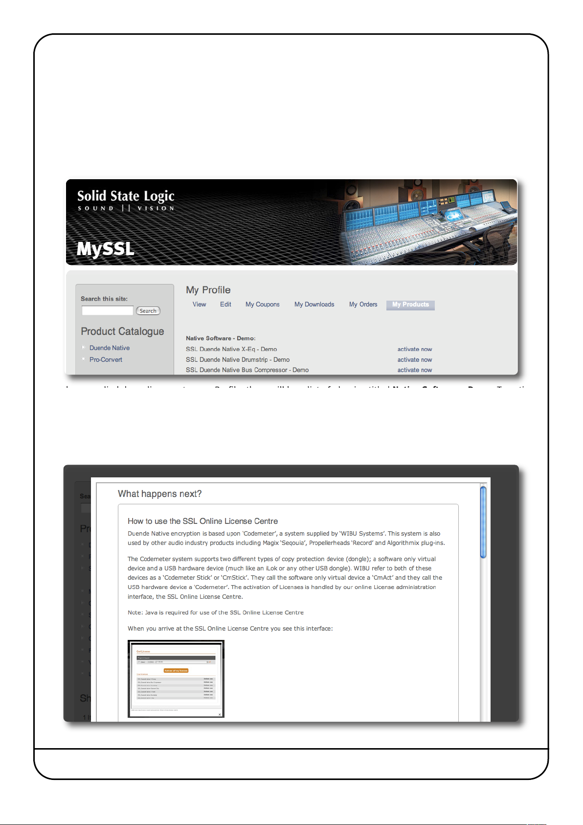
When you log into the website or complete a plug-in purchase, you are automatically taken to the MySSL area. To navigate
there from elsewhere in the website, click on your name in the top right-hand corner of the screen.
Go to the My Products tab within your profile, which will look similar to the below:
If you have applied demo licences to your Profile, there will be a list of plug-ins titled Native Software - Demo. To activate
your free demo periods on any plug-ins, click on the activate now label for one of the plug-ins in the list.
If you have applied full licences to your Profile, there will be a list of plug-ins titled Native Software. To activate your purchased
plug-ins, click on the activate now label for one of them in the list.
You will be taken to the SSL Online Licence Centre:
Duende Native User Guide Page 17
Page 24
Note that the Duende Native encryption is based upon ‘CodeMeter’. You may have other products licenced under CodeMeter,
and you may have a USB hardware CodeMeter dongle.
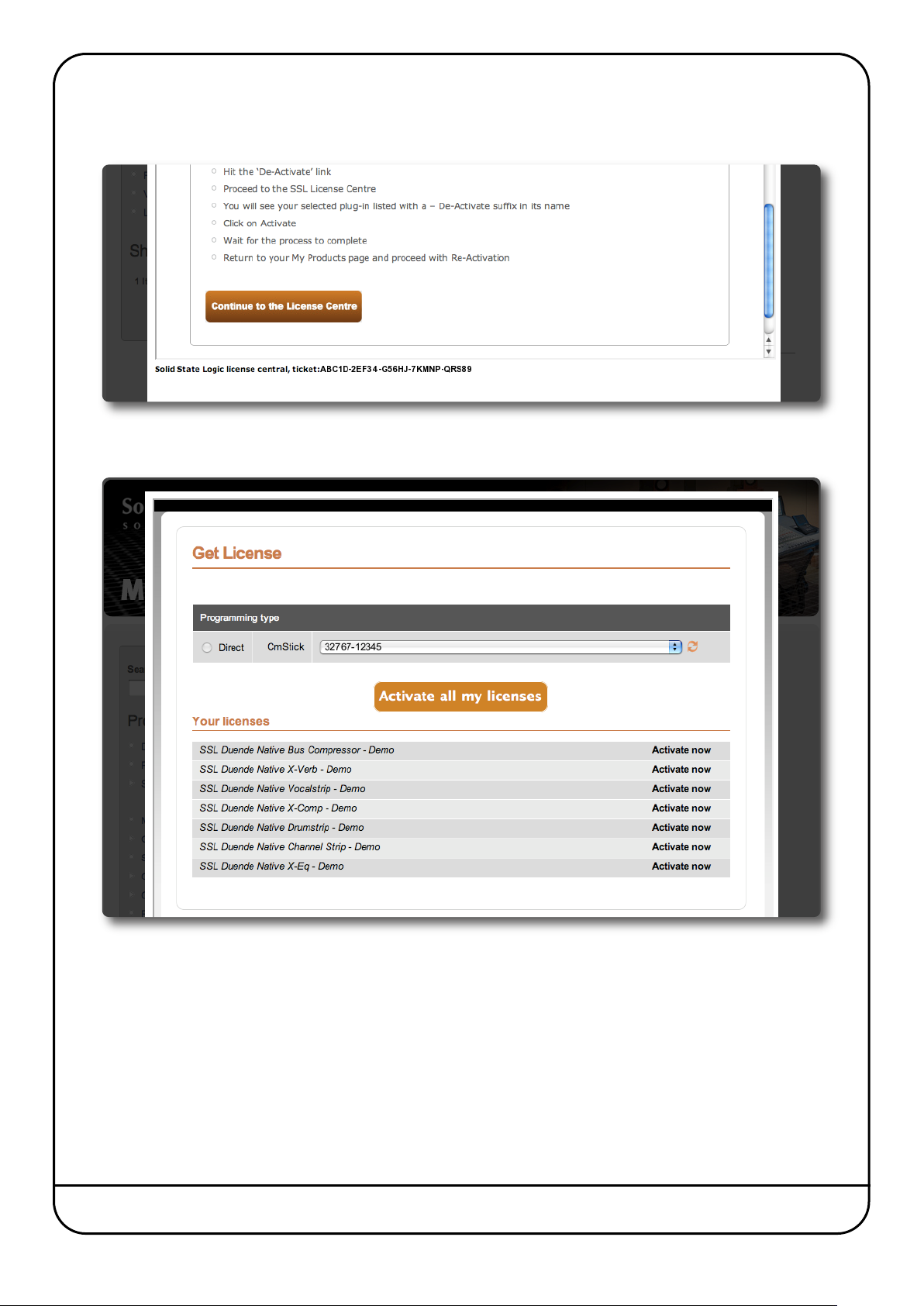
t is important to read the on-screen instructions before clicking on Continue to the Licence Centre at the bottom of the page:
I
A list of plug-ins will appear. Click on the individual Activate Now labels to complete the activation process. If you are ready
to activate all of the licences listed, click on Activate all my licences.
Your plug-ins should now be installed and activated, and should appear in the plug-in list within your host application. You
can run Duende plug-ins simultaneously with your other plug-ins in any combination. Below are the locations of Duende
plug-ins in common audio applications:
Logic: Audio Units > SSL
Cubase/Nuendo: Solid State Logic
Pro Tools: Wrapped Plug-ins
Page 18 Duende Native User Guide
Page 25
2. EQ & Dynamics Channel Strip
INTRODUCTION
The EQ & Dynamics Channel Strip plug-in provides a complete SSL channel strip, modeled on the XL 9000 K Series console,
and includes high and low pass filters, a four band equalizer, compressor/limiter and gate/expander. The channel strip can
run in mono or stereo.
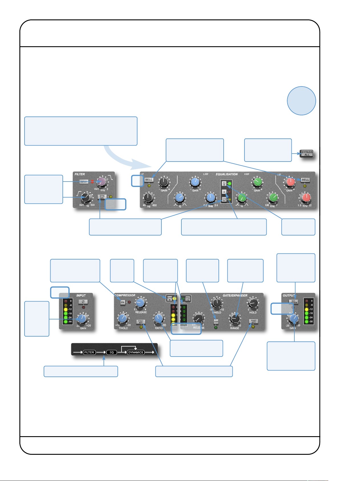
Before examining the plug-in in detail, the diagram below provides an operational overview. If you are
unfamiliar with any of the operations described, you may also want to view SSL’s on-line tutorials (See Page
5 for details). Click on any section of the plug-in to be taken to its description:
Above the main plug-in window is a set of controls
which are specific to your host application.
Please refer to your host application’s user guide
or guidelines on using these controls
f
Turn filter knobs
up to engage.
Black filters LF,
Purple filters HF.
EQ
BELL switches low and
high EQ bands from shelf
to parametric mode.
Internal plug-in
bypass for smoother
A/B comparisons
Filters
DYN S/C assigns Filters and/or
EQ to dynamics side chain.
E switches EQ characteristics between
SSL E and G Series consoles
?
click here for
on-line
tutorials
EQ IN
activates EQ
Turn up
input gain
to a
suitable
level
PK switches signal
detection between
Peak and RMS modes
Input
Signal Processing Order display
DYN IN
engages
Dynamics
Compression
and Expansion
meters
EXP switches
between Gate
and Expander
Dynamics
To activate Compressor
turn up RATIO
FAST ATT introduces a fast attack
To activate
Gate/Expander
turn up RANGE
S/C LISTEN
routes Dynamics
side chain to
channel output
Output
When adjustments
are complete, correct
the output gain to a
suitable level.
Duende Native User Guide Page 19
Page 26

INTERFACE TECHNIQUES
To press a switch in a plugin, simply click on it.
•
To turn a knob, click on it, and drag it up and to the right (as shown right). If your mouse has a scroll
•
heel, you can also turn knobs by hovering over them and turning the scroll wheel.
w
C
+ Drag
lick
• To turn a knob slowly for fine adjustments, hold
• To reset a knob to its default value, click on it whilst holding Ctrl (Windows) or ⌘(Macintosh).
• To view the value for any knob, hover over the knob cap with the mouse.
The current value will appear immediately above the knob (shown right).
Shift on your keyboard whilst turning.
Place mouse
over knob
Value will
appear above
Automation
Every plug-in parameter can be automated in host applications which support automation. The method for recording and
editing automation varies from host to host. For specific instructions on using automation within the host, consult the host
application documentation.
INPUT SECTION
Turn the GAIN knob to control the level of the incoming audio signal. The post-gain signal level is shown
to its left. As a rough guide, the ‘-6’ yellow indicator should occasionally comes on but the red ‘0’
indicator should remain off.
Press Ø to invert the phase of the input signal.
FILTER SECTION
There are two filters in the Filter section:
• The black knob controls an 18dB/Octave high pass filter (20Hz to 500Hz).
• The purple knob controls a 12dB/Octave low pass filter (3kHz to 22kHz ).
Filters are inactive when turned fully left (OUT). Turn them clockwise to move the filter frequency in
from its extremity.
To place the Filters straight after the input control, press INPUT (see previous page), and to switch the Filters into the
Dynamics sidechain, press DYN SC (see Page 27 for more info). Note that these switches cancel each other out.
Page 20 Duende Native User Guide
Page 27

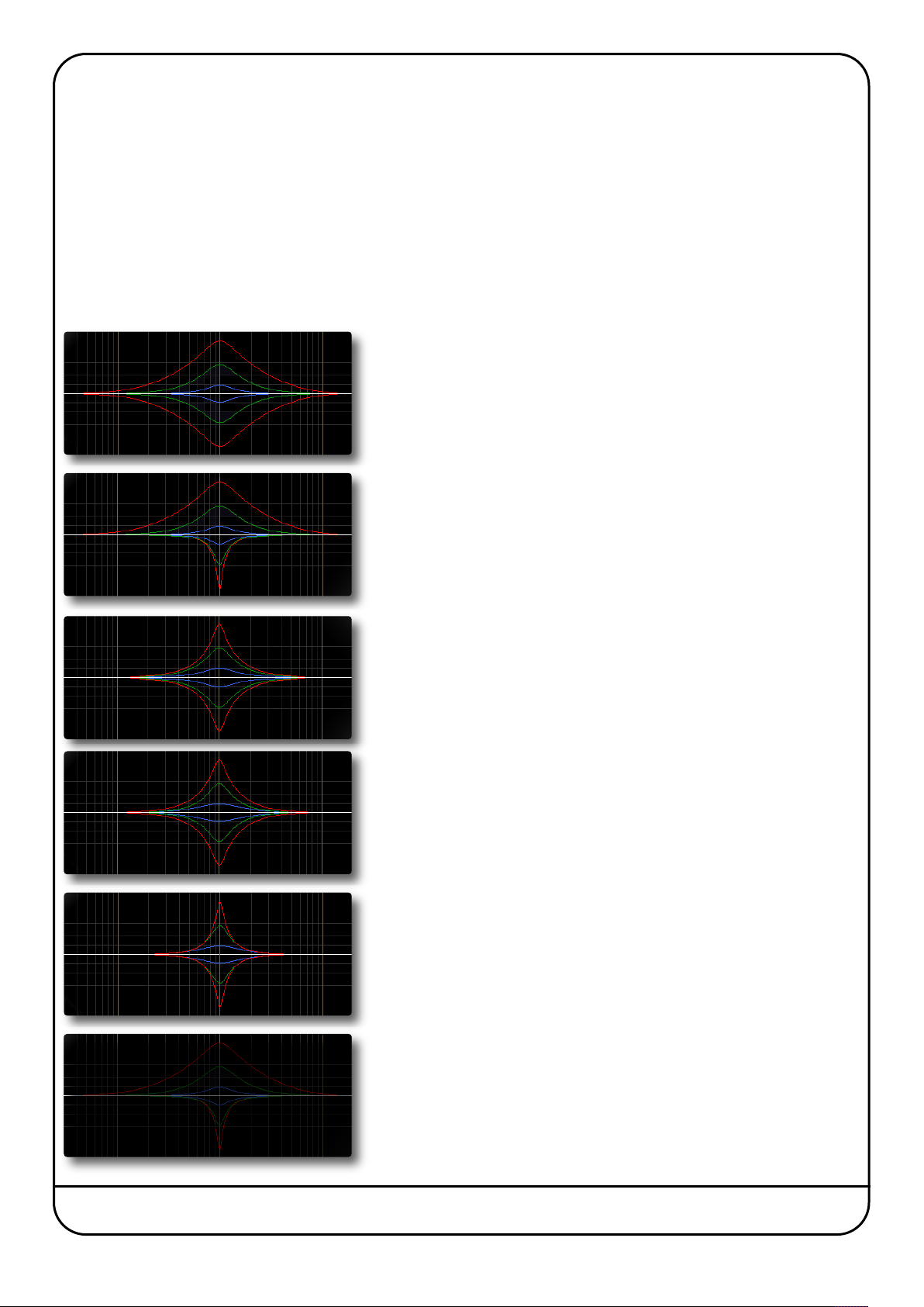
EQUALISER SECTION
10 100 1k 10k 20k
-5.0
0.0
5.0
10.0
15.0
20.0
2
5.0
Amplitude (dBr) v Frequency (Hz)Channel Equaliser Curves
'G type'
'E type'
Both
0.0
25.0
20 100 1k 10k 100k
-5.0
5.0
10.0
15.0
2
0.0
Amplitude (dBr) v Frequency (Hz)Channel Equaliser Curves
'
G type"
'E type'
o use the EQ, switch it into circuit by pressing the EQ IN switch.
T
The EQ section has four bands, each with it’s own knob colour. All bands have gain and frequency control. The low (LF) and
high (HF) bands are shelved by default (as shown below) but can be switched to a bell shape (parametric) by pressing the
BELL button. The low-mid (LMF) and high-mid (HMF) bands also have Q control:
Band LF LMF HMF HF
Frequency
range
Gain range
Q range
40Hz – 600Hz 200Hz – 2kHz 600Hz – 7kHz 1.5kHz – 22kHz
±16.5dB ±20dB ±20dB ±20dB
– 0.5 – 2.5 0.5 – 2.5 –
Press the E to switch the EQ emulation from G Series to E Series consoles.
The diagrams to the right display the difference between them:
G Series: The bell curve has a more rounded shape at low gains, and the shelf
curve overshoots zero slightly at the base of the curve.
G Series EQ is more subtle and is generally more suited to instruments
and vocals.
E Series: The bell curve is slightly more pointed, and there is no overshoot on the
shelf curve.
E Series EQ is more aggressive and is therefore better for removing
problem frequencies. It is generally more suited to drums.
Note. At full boost or cut both curves are identical.
To switch the EQ into the Dynamics sidechain, press DYN SC (see Page 27 for more
info).
Duende Native User Guide Page 21
Page 28

DYNAMICS SECTION
he Dynamics section comprises a Compressor/Limiter and an Expander/Gate. Both sections work
T
ndependently but can be operational at the same time, providing sophisticated control of signal levels. The
i
iagrams down the right-hand side of the page give a simplified overview what each control represents – If
d
ou are unfamiliar with any of the operations described, you may want to view SSL’s on-line tutorials (See
y
age 5 for details).
P
Press DYN IN to switch the Dynamics into circuit. To place the Dynamics before the EQ in the signal chain, press the PRE EQ
switch (See Page 27 for more info on processing order).
Compressor/Limiter
To activate the Compressor/Limiter, turn the RATIO knob
so that it’s ratio is no longer 1:1.
To turn the compressor into a ∞:1 limiter, turn the knob
fully to the right.
input level
Threshold
?
click here for
on-line
tutorials
full scale
Ratio
There is no gain makeup control as the T/HOLD
(threshold) knob controls both the level at which gain reduction is introduced and the
gain make-up, keeping the output level steady regardless of the compression.
RELEASE controls how quickly the level returns to normal after the input level has
dropped below the threshold (measured in seconds). The attack time is adjusted
automatically to match the audio. To choose a constantly fast attack time, press the
FAST ATT switch.
Press the PK button to switch from RMS to peak signal detection. In normal RMS mode
the compressor reacts to the average signal level, and has a soft knee characteristic.
When switched to peak mode, it responds to peak signal level and introduces a hard
knee characteristic, resulting in more dramatic compression.
The level of compression being introduced is shown in the left-hand of the two meters
in the centre of the Dynamics section.
Expander/Gate
To activate the Expander/Gate, turn the RANGE
knob so that it’s range is no longer zero. The
green indicators in the right-hand of the two
meters in the centre of the Dynamics section
show the amount of gain reduction being
introduced.
By default, the Expander/Gate section functions as a gate. To switch to the expander,
press the EXP switch.
The THRESHOLD function uses different levels to ‘open’ the gate to audio and to ‘close’
it again –the level at which the expander opens is higher than the level at which it closes
again. In other words, when the expander is opened, it stays open until the signal level
crosses the quieter ‘close’ threshold. This is known as hysteresis and is very useful as
it allows instruments to decay more naturally. The word ‘Threshold’ normally refers to
the ‘open’ threshold.
Attack
Release
change in 0utput level
input level
Threshold
Higher ratio
(steeper)
for gates
1:1 ratio
below and
above range
Gradient is
shallow or flat
for limiters
output level
time
Full scale
Range
Ratio
output level
HOLD controls the delay before the signal level starts reducing again, and RELEASE
controls how quickly the level then reduces. Note that the RELEASE interacts with the
RANGE, which determines the depth of gain reduction.
The attack time (the time taken for the Expander/Gate to ‘recover’ once the signal level
is above the ‘deactivate’ threshold) is normally set to 1.5ms per 40dB. Press the FAST
ATT switch to introduce a faster attack time of 100µs per 40dB. This is useful when
gating signals with a steep rising edge, such as drums.
change in 0utput level
Hold
Attack
Page 22 Duende Native User Guide
time
Release
Page 29

ynamics Values
D
he value ranges associated with the dynamics controls are as follows:
T
Ratio Threshold / Range Release time Attack time
Compressor 1:1 to ∞:1
Expander
Gate: 40:1
xpander: 2:1
E
–20dB to +10dB 0.1s to 4s
30dB to +10dB
ange: 0dB to 40dB
R
hold 0s to 4s
elease 0.1s to 4s
r
3ms to 30ms (automatic)
3ms in Fast Attack
1.5ms /40dB
00µs /40dB in Fast Attack
1
Side Chain Processing Order
The EQ and filter sections can be assigned to the Dynamics sidechains, allowing for advanced processes like de-essing. This
is done using the DYN S/C switches in the respective sections.
The Process Order display at the base of the plug-in window indicates the sidechain
assignments, as shown to the right. Both EQ and filter sections can be assigned to
the sidechain together, in which case the EQ precedes the filter.
To listen to the signal feeding the side chain, press the S/C LISTEN button in the Output section to route the side chain signal
to the channel output.
Note. Remember to cancel the S/C LISTEN button once you have finished auditioning the side chain!
CHANNEL PROCESSING ORDER
Signal processing order is shown in the graphic at the bottom of the plug-in window.
The default plug-in order is Filters ® EQ ® Dynamics.
To place the after the EQ section, deactivate the INPUT switch in the Filters section
The INPUT indicator should go off.
To place the Dynamics before the EQ, press the PRE EQ switch in the Dynamics
section.
When the INPUTand PRE EQ switch are active simultaneously, the processing order
becomes Filters ® Dynamics ® EQ.
OUTPUT SECTION
The Output section allows you to ensure that the signal retains a good level after all the signal processing.
The signal level is shown to the right of the knob. As a rough guide, the ‘-6’ yellow indicator should
occasionally comes on but the red ‘0’ indicator should remain off.
S/C LISTEN routes the sidechain directly to the output, so you can monitor the sidechain signal.
Duende Native User Guide Page 23
Page 30

Blank page – well, nearly
Page 24 Duende Native User Guide
Page 31

3. Stereo Bus Compressor
INTRODUCTION
The Stereo Bus Compressor plug-in is a stereo version of the legendary centre section stereo bus compressor found on the
XL 9000 K Series console. It provides high quality stereo compression, giving you critical control over the dynamic range of
audio signals.
The compressor can be run in mono or stereo modes and can be used for practically any application that requires superior
compression. For example, place it over a stereo mix to ‘glue’ the mix together whilst still maintaining a big sound, or use it
on drum overheads or whole drum kits for very effective control of drum dynamics.
INTERFACE TECHNIQUES
• To press a switch in a plugin, simply click on it.
• To turn a knob, click on it, and drag it up and to the right (as shown right). If your mouse has a scroll
wheel, you can also turn knobs by hovering over them and turning the scroll wheel.
• To turn a knob slowly for fine adjustments, hold Shift on your keyboard whilst turning. To reset a knob to
its default value, click on it whilst holding Ctrl (Windows) or ⌘(Macintosh).
• To view the value for any knob, hover over the knob cap with the mouse. The current value will appear
immediately above the knob (shown left).
Every plug-in parameter can be automated in host applications which supports automation. The method
for recording and editing automation varies from host to host. For specific instructions on using automation
with the host consult the host application documentation.
k + Drag
lic
C
Value
appears here
when mouse
is over knob
?
click here for
on-line
tutorials
CONTROL PARAMETERS
Below is a description of the Stereo Bus Compressor’s parameters, as shown in the diagrams
to the right. If you are unfamiliar with how to use any of the parameters described, please
refer to SSL’s on-line tutorials (See Page 5 for details).
Compression Meter
Shows gain reduction in dB
THRESHOLD
Controls level at which gain
reduction is introduced.
Continuously variable:
–20dB to +20dB.
ATTACK
Controls response time
when Threshold is crossed.
Choose between:
0.1, 0.3, 1, 3, 10 and 30ms.
RATIO
Controls the degree of
compression.
Choose between:
2:1, 4:1 and 20:1.
MAKE-UP
Controls level
compensation to offset
compressor action.
Continuously variable:
–5dB to +15dB.
RELEASE
Controls how quickly
level returns to normal.
Choose between
0.1, 0.3, 0.6, or
1.2 seconds, or Auto.
Auto: release time is
dependant upon
duration of signal peak.
COMP IN
Switches the
compressor in and out
of the signal path.
input level
Make-up
Attack
change in 0utput level
full scale
Threshold
Ratio
Gradient is
shallow or flat
for limiters
output level
Release
time
Duende Native User Guide Page 25
Page 32

Blank page – well, nearly
Page 26 Duende Native User Guide
Page 33
4. X-Comp
INTRODUCTION
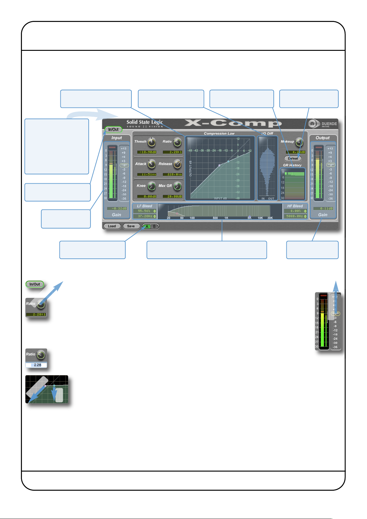
The illustration below gives an overview of some of the X-Comp features which are described in full over the following pages.
Click on the blue boxes to be taken to fuller descriptions of their contents.
Interactive compressor
display with draggable nodes
Above the main plug-in
window is a set of controls
which are specific to your
ost application.
h
Please refer to your host
application’s user guide
for guidelines on using
these controls
Internal bypass for smooth
in/out comparisons
Input level metering
and control
Switch between main and
alternative plug-in settings
IO Diff display displays the
signal’s dynamic range.
Bleed section allows LF and HF bands to bypass
the compressor. Display includes draggable nodes
GR History displays gain
reduction over last second
Defeat button for
auditioning bleed signal
Output level
metering and control
INTERFACE TECHNIQUES
To press a switch in a plugin, simply click on it. A green surround indicates that the switch
is in its active state.
Click + Drag
Threshold
Automation
Every plug-in parameter can be automated in host applications which support automation. The method for recording and
editing automation varies from host to host. For specific instructions on using automation within the host, consult the host
application documentation.
To turn a knob, click on it, and drag it up and to the right. If your mouse has a scroll wheel,
you can also turn knobs by hovering over them and turning the scroll wheel.
To control Input and Output levels, click and drag upwards (see right).
To move any control slowly for fine adjustments, hold Shift on your keyboard whilst turning.
To reset a knob to its default value, click on it whilst holding Ctrl (Windows) or ⌘(Macintosh).
To enter a precise value for any parameter, double-click on its value display, enter a value
on your computer keyboard, and press the Return key.
Threshold and Ratio values can also be controlled directly within the Compression Law display. Move the
pink node along its line to control the Threshold, and move the blue node up and down to control the
ratio.
Ratio
The bleed bands can be adjusted in a similar way, as described on Page 33.
Click + Drag
Duende Native User Guide Page 27
Page 34
CONTROL PARAMETERS
Plug-in Bypass
The In/Out switch located above the Input section provides an internal plug-in bypass. This allows for smoother
In/Out comparisons by avoiding the latency issues associated with the host application’s Bypass function.
The button must be ‘lit’ for the compressor to be in circuit (as shown right).
Presets
The Load and Save buttons at the base of the screen provide quick access to the host application’s Import
and Save Settings functions. For specific instructions on using presets within the host, consult the host
application documentation. Presets use a standard file format which allows them to be moved between a variety of platforms
and host applications.
A file of ready-made X-Comp presets are included in the plug-in installation. These provide starting points for a variety of
instruments and effects. To load SSL presets, click on the Load button and navigate as follows:
Macintosh:
Windows:
/Applications/Solid State Logic/Presets/X-Comp
c:\program files\solid state logic\presets\X-Comp
A-B comparisons
The A B button at the base of the screen allows you to load two completely independent set ups and compare
them quickly. When the plug-in is opened, setting A is selected by default, as shown right. Pressing the A B button
will switch between setting A and setting B.
You may wish to use this function to compare two very similar settings or to keep a ‘maybe’ setting in reserve if your current
one does not work out.
Common Compressor Parameters
?
click here for
on-line
tutorials
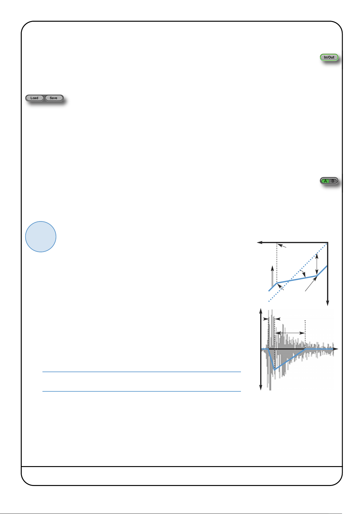
Knee
The Knee controls how focussed the threshold level is:
- With a hard knee (knob at minimum) the compressor’s parameters all come into
force at precisely the point at which the threshold is crossed. In the Compression
Law diagram, this is shown by a sharp change in gradient at the threshold.
- With a soft knee, the ratio is introduced gradually, starting below the threshold
and reaching its full value above the threshold. In the Compression Law graph,
this is shown by a curve in the gradient around the threshold.
The diagrams down the right-hand side of the page give a simplified
overview what each control represents, as shown in the Compression
Law display in the centre of the plug-in window. If you are unclear
about how the Thresh (threshold), Ratio, Attack, Release and Make up
work, please refer to SSL’s on-line tutorials (See Page 5 for details).
input level
Make-up
Attack
full scale
Thresh
Max GR
Ratio
Hard knee: sharp
Soft knee: curved
Release
output level
The Knee control affects both the main threshold point and the Max GR point (see
below) in equal measure.
Operational tip. A hard knee allows for greater precision, but can sound more
obvious. A soft knee generally provides a more transparent result.
change in 0utput level
time
Max GR
The Max GR (Maximum Gain Reduction) allows you to set a limit on how much gain reduction can be introduced, replicating
the performance of older optical compressors (as shown in the upper diagram to the right). With a Max GR of 20dB, for
example, any signals that would normally be reduced by more than 20dB will be attenuated by 20dB. By only compressing
the middle of the dynamic range, you can exert some general dynamic control whilst still preserving the affect of a signal’s
peaks.
Page 28 Duende Native User Guide
Page 35
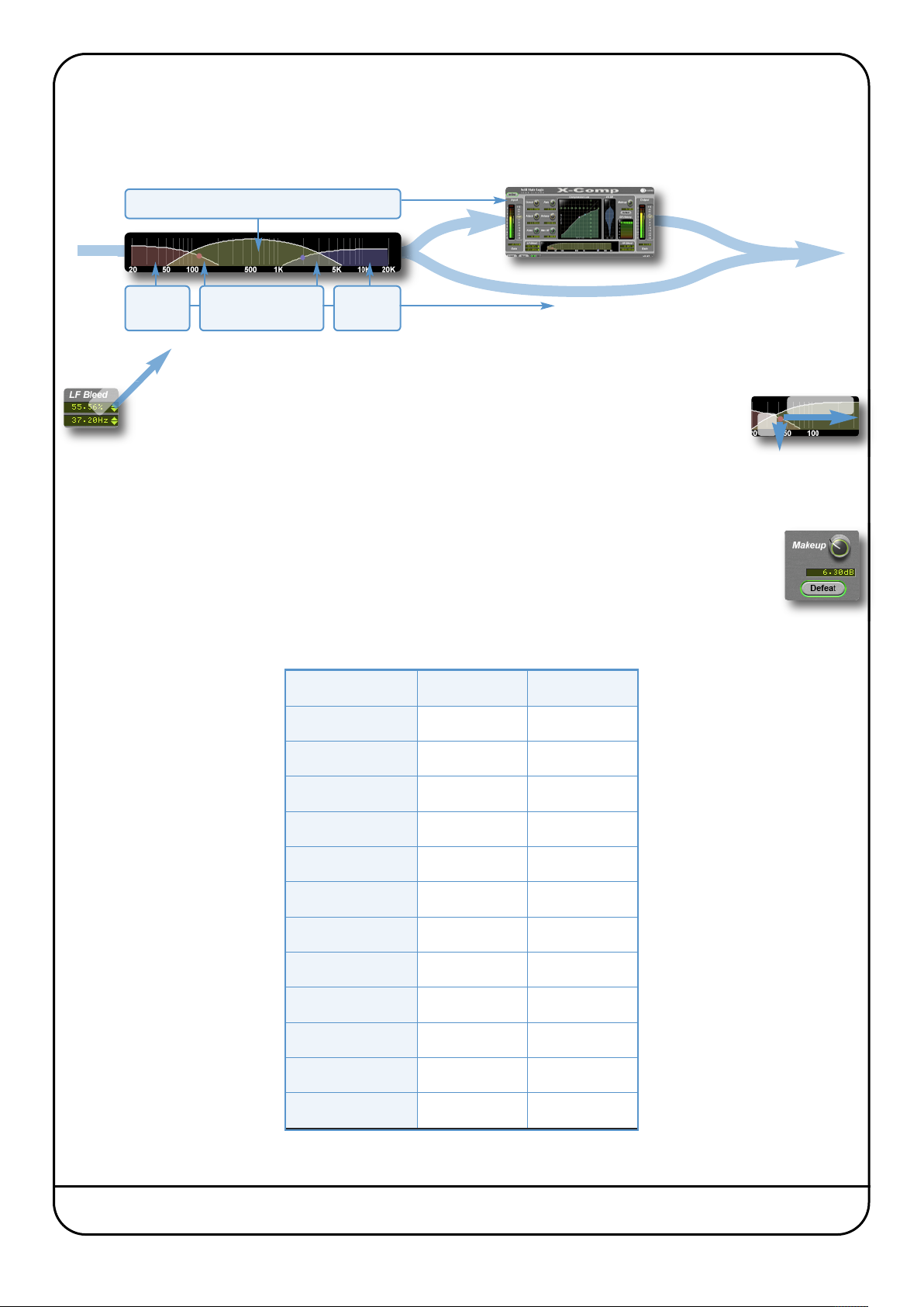
leed
B
he Bleed controls, located at the bottom of the X-Comp plug-in window, allow you to remove the compressor’s effect from
T
igh and low frequencies. Frequencies outside the mid-band bypass the compressor and are recombined with the compressed
h
ignal at the output. Note that the bypassed signal is not affected by the Make up gain.
s
Mid-band is compressed in the normal way
input
Click
LF bypass
region
g
a
Dr
+
‘Cross-fade’ regions
defined by bleed %
HF bypass
region
bypass
The frequencies and slope of the bleed-band filters are indicated either side of the graph; LF to the left
and HF to the right. The slope is measured in percentage.
The bleed bands can be adjusted by clicking on the values in the displays and
dragging up and right in the usual way. Alternatively, they can be adjusted directly
using the nodes in the display – brown for low frequencies and blue for high
frequencies. Move the nodes horizontally to control frequency and vertically to
control percentage
Auditioning Bleed Bands
To listen to the bleed bands on their own, press the Defeat button, located below the Make up gain.
This mutes the compressed signal, so only the bypass portion of the signal is heard.
COMPRESSOR VALUES
The table below lists the ranges of all of X-Comp’s parameters:
output
Frequency
%
Parameter Min Max
Input gain –36db +12dB
Threshold –48dB +12dB
Ratio 1:1 50:1
Knee 0dB 40dB
Max GR 20dB 60dB
Attack time 0.5ms 100ms
Release time 1ms 2000ms
Make up gain –6dB +36dB
LF Bleed 30Hz 300Hz
HF Bleed 2kHz 12kHz
Bleed slopes 0% 100%
Output gain –36db +12dB
Duende Native User Guide Page 29
Page 36
nput and Output Sections
I
he input and output sections at either side of the plug-in window provide input and output gain control, along with displays
T
f the following information:
o
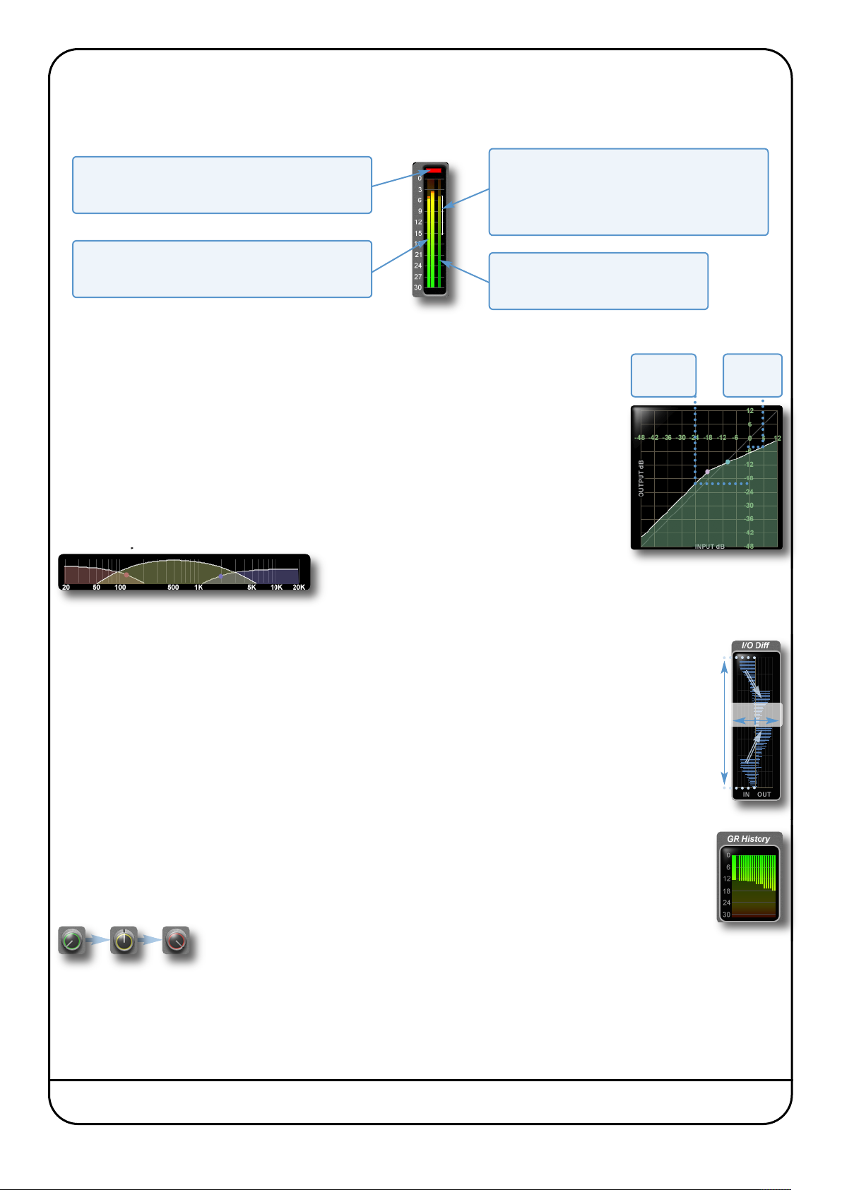
ange Meter
Clip Light
Indicates that the signal is clipping. It clears after 1
econd, or click on it to clear manually.
s
The thin white bracket indicates the signal’s recent
dynamic range. Longer brackets indicate a larger
ynamic range. If the bracket edges are moving
d
quickly, this implies an ‘energetic’ signal.
R
Peak Meter
Allows you to observe the exact level at any point in
time. There are two meters in stereo and one in mono.
The thinner bar to the right shows the
RMS (average) level over time.
RMS Meter
Compression Law Graph
The display in the centre of the plug-in window compares the input and output signals given the
current compressor settings. The thicker white line indicates the relationship between input
and output across the range of levels, while the faint line indicates a 1:1 relationship. In the
example to the right, an input level of –24dB results in an output level of –20dB (as this is below
the threshold, this indicates a Make-up gain of 4dB), while an input level of +6dB results in an
output level of –4dB.
Threshold and Ratio can be defined by moving the nodes within the display: Move the pink
node along its line to control the Threshold, and move the blue node up and down to control the
ratio.
In: -24dB
Out: -20dB
Bleed Graph
The bleed graph indicates the frequencies which
are bypassing the compressor, as described on
the previous page.
I/O Diff Graph
The I/O Diff meter to the right of the Compression Law graph shows how often each level occurs within
the input and output signals. The input is shown on the left and the output on the right.
In: 6dB
Out: -4dB
0dB
The vertical scale is amplitude, with 0dB at the top and –∞ at the bottom. The length of each line
protruding from the centre represents the number of incidents of that amplitude over a period of seconds.
In the graphic to the right, the input signal displays a mixture of very loud and very quiet, indicating that
the signal has a large dynamic range which is changing very quickly. The output signal indicates that this
dynamic range has been made smaller, with the loud bars being reduced in level and the quiet bars
being increased.
GR History
The GR History (Gain Reduction History) meter shows the current gain reduction and how it has fluctuating.
The thicker line towards the left of the display shows how much gain reduction is currently being used,
while the thinner lines to its right show how this has been changing over the past second.
Colour of knobs
You may also notice that the colour of the knob surrounds change to indicate
their level – green for low, yellow for mid, red for high.
Incidence
Amplitute
–∞
Page 30 Duende Native User Guide
Page 37
5. X-EQ
INTRODUCTION
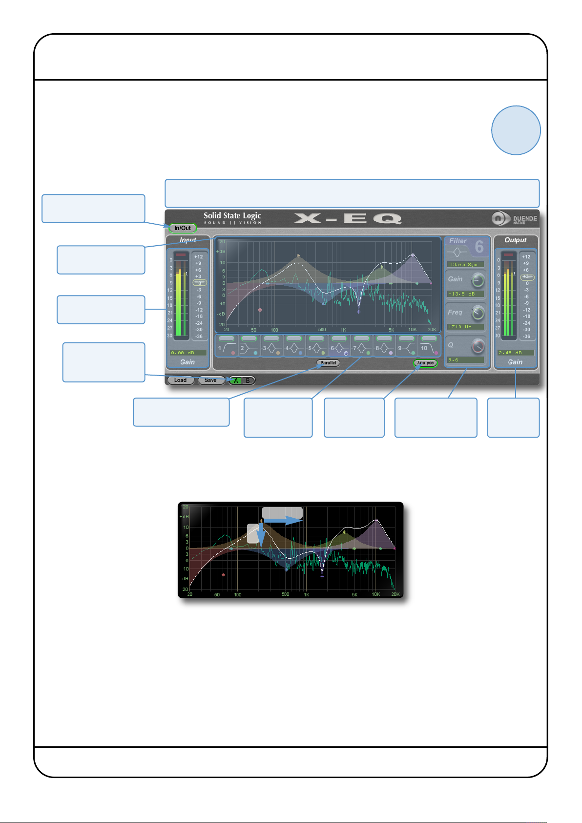
X-EQ is a 10-band highly configurable EQ plug-in. The six central bands have bell curves, the second and ninth
bands are shelf bands, while the first and last bands are filters. The illustration below introduces some of the
X-EQ plug-in features which are described in full over the following pages. Click on the blue boxes to be taken
to fuller descriptions of their contents. If you are unclear on how to use an EQ, then it may be worth starting
with the SSL on-line tutorials (See Page 5 for details).
Above the main plug-in window is a set of controls which are specific to your host application.
lease refer to your host application’s user guide for guidelines on using these controls
Internal bypass for smooth
in/out comparisons
Interactive EQ display
with draggable nodes
Input level metering
and control
P
?
click here for
on-line
tutorials
Switch between
main and alternative
plug-in settings
Switches between Serial
and Parallel signal-flow
Activates bands
and assigns
them to Edit area
Displays graph
of frequency
content
INTERFACE OVERVIEW
EQ Graph Display
The EQ graph provides visual feedback for a number of things:
Frequency
Gain
The white line across the graph shows the frequency response of the current EQ settings.
Edit area for the
band selected below
the main graph
Output level
metering
and control
The nodes represent the settings of each individual band, and can be dragged to change the settings:
- For the eight central EQ bands, move the nodes left and right to control Frequency, or up and down to control Gain.
- For the filter bands (Bands 1 and 10), move the nodes left and right to control Frequency, or up and down to control Slope.
Each band is colour coded, with the graph node colour matching the coloured dots in their band box below the graph. Each
coloured shade area represents the impact of the node with that colour.
The real-time frequency content of the processed signal can be displayed by clicking on the Analyse button below the display.
Duende Native User Guide Page 31
Page 38
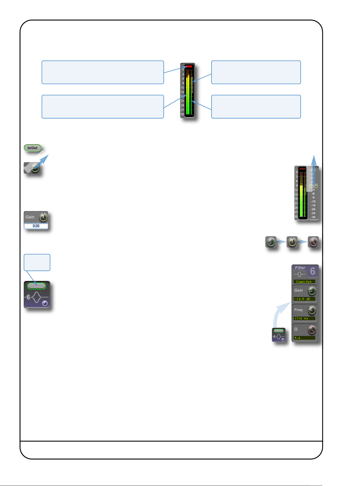
nput and Output Sections
I
he input and output sections at either side of the plug-in window provide input and output gain control, along with displays
T
f the following information:
o
Indicates that the signal is clipping. It clears after 1
second, or click on it to clear manually.
Allows you to observe the exact level at any point in
time. There are two meters in stereo and one in mono.
Interface Techniques
To press a switch in a plugin, simply click on it. A green surround indicates that the switch is in its active state.
g
a
Dr
+
ck
i
Cl
To turn a knob, click on it, and drag it up and to the right. If your mouse has a scroll wheel,
you can also turn knobs by hovering over them and turning the scroll wheel.
To control Input and Output levels, click and drag upwards (see right).
To move any control slowly for fine adjustments, hold Shift on your keyboard whilst
turning.
To reset a knob to its default value, click on it whilst holding Ctrl (Windows) or ⌘(Macintosh).
To enter a precise value for any parameter, double-click on its value display, enter a value
on your computer keyboard, and press the Return key.
lip Light
C
Peak Meter
ange Meter
R
The thin white bracket indicates the
signal’s recent dynamic range.
RMS Meter
The thinner bar to the right shows the
RMS (average) level over time.
Click + Drag
You may notice that the colour of the knob surrounds change to indicate their level:
green for low, yellow for mid, red for high.
Band ‘on’
switch
To switch each band on, click on the oblong switch at the top of each band box.
The edit controls to the right of the EQ graph control one of the 10 EQ bands. The band
being controlled is selected by clicking on the appropriate band box, located in a row
underneath the graph, or by clicking on the band’s node in the EQ graph.
The band assigned to the edit controls is indicated by the band box being ‘lit’ with its
band colour, and by the band number and colour appearing at the top of the edit
controls, as shown right for band 6.
Automation
Every plug-in parameter can be automated in host applications which support automation. The method
for recording and editing automation varies from host to host. For specific instructions on using
automation within the host, consult the host application documentation.
Page 32 Duende Native User Guide
Page 39
EQ CONFIGURATION
hen one of the band boxes below the EQ graph is selected, it’s band is assigned to the band editing controls to the right of
W
he graph.
t
- Freq (frequency) control is provided for each band.
- Gain and Q control is provided for all bands apart from the filter bands (Band 1 and 10).
The filter bands have slope control in place of the Q control.
-
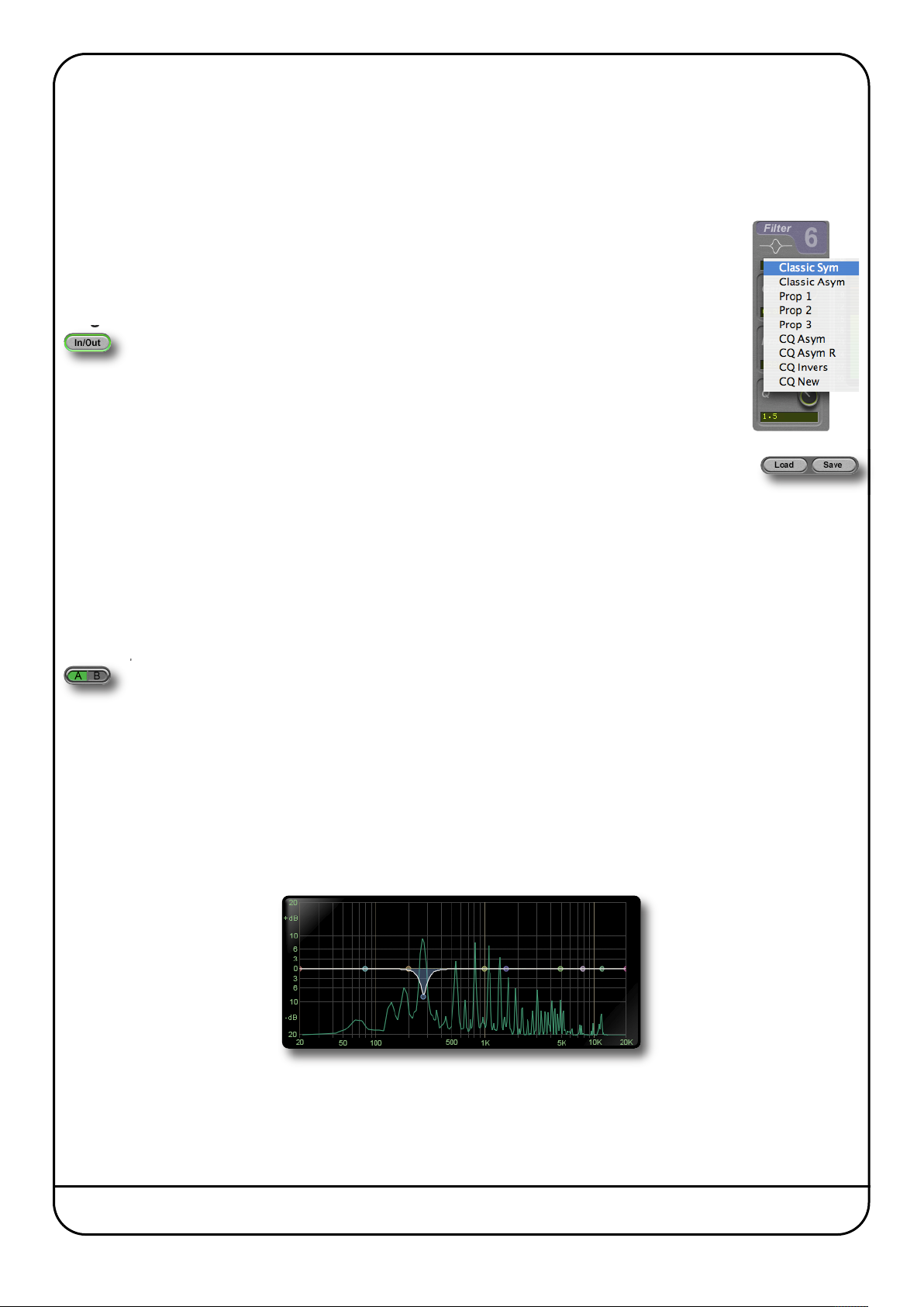
- In addition, you can select from a number of filter shape types by clicking on the text box above the
gain control and selecting a shape from the drop-down list which appears. These shapes are described
on Page 39 and following. Note that there are no shape types available for the shelving bands (Bands
2 and 9).
Plug-in Bypass
The In/Out switch located above the Input section provides an internal plug-in bypass. This
allows for smoother In/Out comparisons by avoiding the latency issues associated with the
host application’s Bypass function.
The button must be ‘lit’ for the compressor to be in circuit (as shown left).
Presets
The Load and Save buttons at the base of the screen provide quick access to the host application’s Import
and Save Settings functions. For specific instructions on using presets within the host, consult the host
application documentation. Presets use a standard file format which allows them to be moved between
a variety of platforms and host applications.
A file of ready-made X-EQ presets are included in the plug-in installation. These provide starting points for a variety of
instruments and effects. To load SSL presets, click on the Load button and navigate as follows:
Macintosh:
Windows:
/Applications/Solid State Logic/Presets/X-Eq
c:\program files\solid state logic\presets\X-Eq
A-B comparisons
The A B button at the base of the screen allows you to load two completely independent set ups and compare
them quickly. When the plug-in is opened, setting A is selected by default, as shown right. Pressing the A B button
will switch between setting A and setting B.
You may wish to use this function to compare two very similar settings or to keep a ‘maybe’ setting in reserve if your current
one does not work out.
Analyse
If the Analyse button is pressed, a display of the input signal’s frequency response is shown within the EQ graph.
This allows problem frequencies to be pinpointed visually and filtered out by moving the nodes within the graph, such as in
the example below. As the analyser is placed post-EQ, you can see what effect the processing has on the frequency spectrum.
Duende Native User Guide Page 33
Page 40
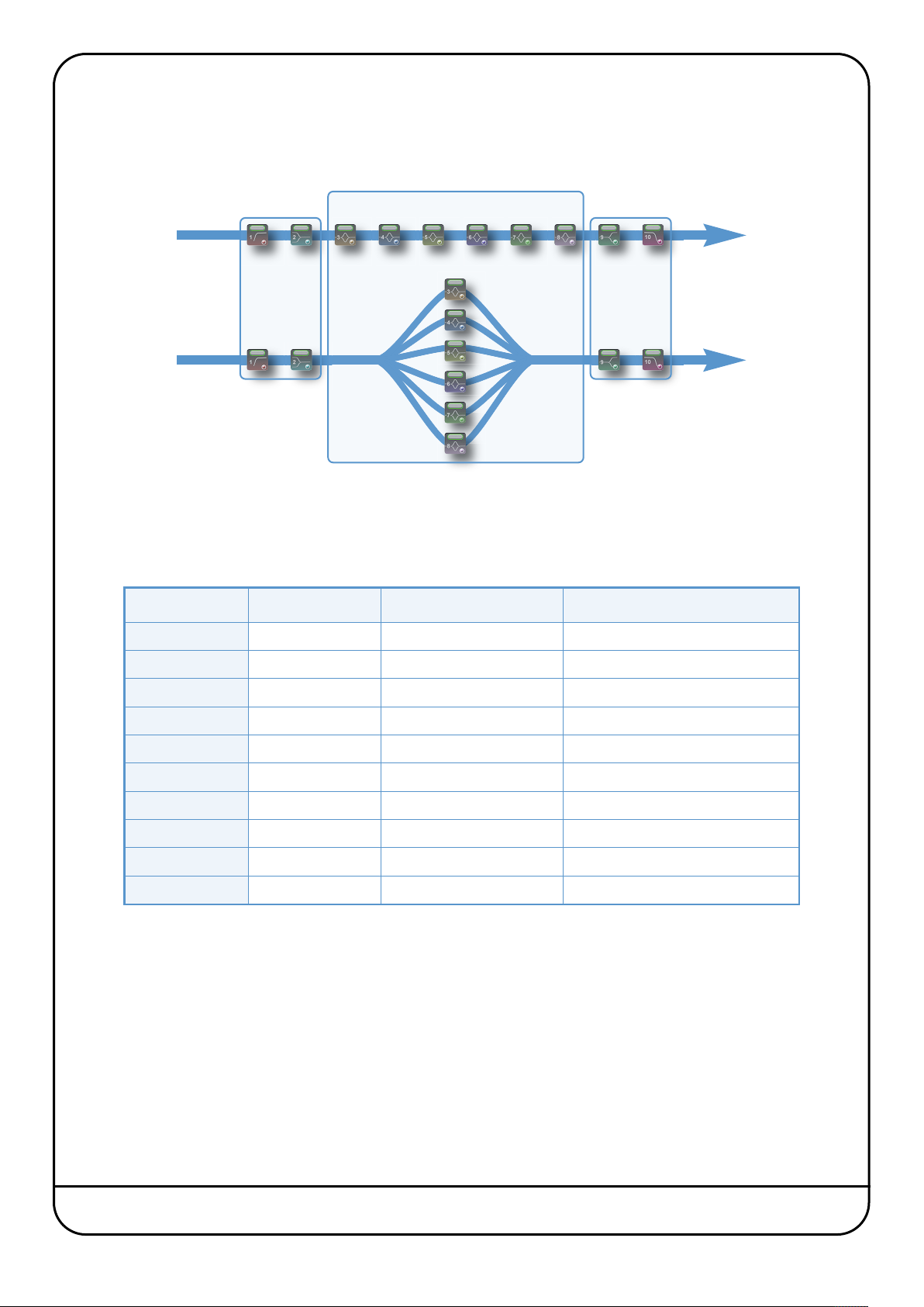
arallel
P
he parallel button changes the order in which the six central bell-shaped bands are processed. In normal (serial) mode, they
T
re processed one after the other. In parallel mode, once the signal has passed through the LF filter and shelf bands, it is split
a
ff and routed through each bell band simultaneously, before being combined again for the HF shelf and filter bands:
o
6 Bell Bands
Serial
Parallel
LF Filter
nd Shelf
a
EQ
HF Shelf
Q and
E
Filter
The parallel EQ is modelled on the old ‘Parallel Passive’ EQ units, and the different style of band interaction means that the
EQ performs quite differently. See the EQ History section on Page 41 for more information.
EQ PARAMETER VALUES
Band Gain Frequency Q
HP Filter n/a 20Hz – 1020Hz 0 – 48dB/oct in 6dB steps
Low Shelf ±20dB 20Hz – 1020Hz 0.3 – 10.3
Midband 1 ±20dB 20Hz – 20kHz 0.3 – 10.3
Midband 2 ±20dB 20Hz – 20kHz 0.3 – 10.3
Midband 3 ±20dB 20Hz – 20kHz 0.3 – 10.3
Midband 4 ±20dB 20Hz – 20kHz 0.3 – 10.3
Midband 5 ±20dB 20Hz – 20kHz 0.3 – 10.3
Midband 6 ±20dB 20Hz – 20kHz 0.3 – 10.3
High Shelf ±20dB 500Hz – 20kHz 0.3 – 10.3
LP Filter n/a 500Hz – 20kHz 0 – 48dB/oct in 6dB steps
Page 34 Duende Native User Guide
Page 41
EQ AND FILTER SHAPES
Bell Shapes
Q Definitions:
P – 3dB Classical definition that means Q is measured 3dB below peak for boost or 3dB above peak for cut.
– 3dB Definition used for bells in some US products, the bandwidth for Q calculation is measured 3dB below 0dB
0
ine for cut or 3dB above for boost. Q in both definitions correct only for +6dB boost/cut.
l
P/2 New ‘musical’ definition based on the bandwidth measurement in the middle of a bell filter, between peak
and 0dB line.
Normalisation 12 equalisers are normalised to have exactly the same bell shape for +6dB boost.
Classic Symmetrical (Classic Sym)
The most popular parametric EQ shape used in various mixing consoles and
outboard gear. Almost constant Q characteristic.
P – 3dB
Classic Asymmetrical (Classic Asym)
Often features in older equalisers. Boost as above but much narrower cut
characteristic.
P – 3dB boost
0 – 3dB (x2) cut
Proportional 1 (Prop 1)
Proportional equalisers are recognised as being more ‘musical’ than Constant
Q. The bells are wider below +6dB and narrower above +6dB (or –6dB for cut).
Proportional 2 (Prop 2)
Like Proportional 1 but with larger changes below and above +6dB peak
(or –6dB for cut).
P –3dB
Proportional 3 (Prop 3)
Like Proportional 1 but with extra widened bells between 0 and +3dB
(or –3dB for cut).
P – 3dB
Constant Q Asymmetrical (CQ Asym)
Used in some US products and mixers. The boost characteristics are defined
according to 0 – 3dB formula. Extra widened between –3dB and 0dB.
P – 3dB boost, 0 – 3dB cut
Duende Native User Guide Page 35
Page 42

Constant Q Asymmetrical Reverse (CQ Asym R)
xactly like above but with mirrored boost and cut characteristics.
E
Constant Q Invert (CQ Invers)
Both boost and cut characteristics are both defined according to 0 – 3dB
formula.
0 – 3dB
Constant Q New (CQ New)
Defined Q is always perfectly maintained independent of bell gain (also
below 6dB). In terms of P – 3dB definition of this equaliser can be classified
as proportional.
P/2
Parallel
Note this is accessed via the Parallel switch, not the drop-down menu.
Recreates the passive LC parallel equaliser with all its advantages (sound)
and disadvantages (band interaction, asymmetry). As found in graphic
equalisers.
Shelving Bands
Filter Shapes
3dB boost, 0 – 3dB (x2) cut
Low and High shelves
Q value is used to control overshoot characteristic. On the left is the Low
shelf filter with a low Q value, on the right the High shelf filter exhibits
overshoot with a large Q value.
Note that there are no alternative shapes for shelving bands
Critical
‘Critical Damped’ filters simulate a chain of passive analogue RC (for highcut) and CR (for low-cut) stages fixing a behaviour similar to a series of RC
elements in vintage analogue equipment.
Bessel
Linear phase behaviour leads to no overshoot or ringing resulting from a
sudden transition between signal levels. The drawback is a sluggish roll-off
rate.
Page 36 Duende Native User Guide
Page 43

EQ HISTORY
Gaussian
o ringing or overshoot in the time domain, but slow roll-off in the frequency
N
omain.
d
Butterworth
Characterised by having a maximally flat magnitude response, ie. no
amplitude ripple in the passband.
Chebychev
Characterised by having an equiripple magnitude response, meaning the
magnitude increases and decreases regularly from DC to the cutoff
frequency.
An Audio Engineer’s Best Friend
The equaliser is the oldest and the most popular sound processing tool. From the earliest days, its main function has been
to correct or enhance sound by boosting or cutting certain frequency ranges. Engineers have developed countless equalisers
for over 50 years and some of them became legendary and were considered bench marks. The most popular type of EQ in
recording and post-production studios is the parametric equaliser or PEQ. It offers maximal flexibility due to direct access to
all relevant filter parameters. Properly used the PEQ is a very powerful tool and the best friend of every sound engineer in the
battle for perfect sound. If misused, it can be the greatest enemy of any recording.
The Best of the Analogue and Digital Worlds
X-EQ is a creative equalising tool combining the best of both the analogue and digital worlds. We recreated the most legendary
analogue equalisers and added a few experimental characteristics only possible the in digital domain. By using proprietary
filter algorithms, we have achieved a huge dynamic range as well as extremely low noise and distortion level, and thus
unparalleled sound purity; impossible with any analogue circuitry.
Analogue Parametric EQ Modelling
In today’s era of digital audio workstations, hundreds of software parametric equalisers are available. Many of them are
intended to be “THE best sounding equaliser ever”. The truth is that only few of them are recognised and adored by the
experts. You may ask why one equaliser sounds great while another does not. This question is almost as old as the equaliser
itself and still is not completely answered. On the one hand there are some obvious rules which must be followed when
designing a good sounding PEQ, on the other hand some never really proven esoteric claims driven by marketing departments
or self-nominated audio evangelists. Especially treasured analogue equalisers are considered by some people as being
absolutely unique and unmatched by any ‘dirty’ digital equaliser. The truth is that with a properly designed, fully parametric
analytic EQ every amplitude and phase characteristic of any other equaliser setup can be recreated. Of course, the contribution
of distortions to the specific sound of a particular analogue equaliser caused by the respective electronics has to be
considered. If the distortions are ‘good’, they may make certain applications sound better. Usually however, ‘bad’ non linear
distortions and other deficiencies like limited dynamic range are surely not responsible for a ‘magic’ sound. Therefore our
policy in digital PEQ design has always been to make the equaliser filters as precise and clean as possible. For controlled
generation of distortions we recommend using enhancers or any other specialised processors with proper built-in anti-aliasing
technology.
Duende Native User Guide Page 37
Page 44

on Linear-phase EQ
N
hase shift in equipment is probably one of the most misunderstood topics in audio. Phase shifts often get blamed for
P
nything that is not classed as typical distortion. The reality is that all analogue EQs produce a deviation from linear phase
a
hich is specifically related to the shape of the EQ curve, and it is precisely these phase changes which produce the required
w
ain reductions. This is a very natural process which can be found in the audio characteristics of rooms, materials and
g
lsewhere.
e
Though it is not possible for us to detect phase in isolation, the phase shift of an EQ can often be the cause of the ‘magical’
sound of that device once the EQ signal is added back into the mix. For example, the Duende channel EQ derived from the
SSL analogue consoles – plenty of phase shift and plenty of magic!
In contrast, a linear-phase EQ delays all frequencies by the same amount. This can only be achieved in the digital domain by
using special techniques. While this process is very effective in certain situations (eg. ‘surgically’ removing troublesome
frequencies), it should not be considered as a superior tool for the majority of EQ tasks.
Linear-phase equalisers have become popular over the past few years due to the proliferation of powerful digital processors.
We decided not to go down that route with X-EQ and we think you’ll agree with that decision. Maybe linear-phase EQ is
something we will explore in the future but… who knows? An equaliser not only changes the relative frequency balance of a
signal but also its phase. If you EQ a sound until it sounds right or natural, then the chances are that you are EQing to make
it sound in phase with the rest of the mix. We need say no more on this subject.
Parallel Passive EQ
Parallel EQ exhibits quite different sonic properties to the familiar serial parametric EQ. We are generally used to hearing the
effect of one EQ band superimposed on another, as opposed to the band interaction inherent to a parallel EQ. Because the
bands are placed in a parallel configuration, phase cancellations and re-enforcements happen which is not always obvious
when first encountered.
Passive EQ is something that is found in old equaliser units and is generally known for its transparent and natural sound, but
has some problems associated with it. However, in the digital domain these shortcomings do not have such an influence.
A passive EQ does not have any gain elements, but can still have controls to seemingly boost frequencies as well as cut.
What actually happens is that the entire signal is cut by an amount, but the frequencies which are apparently ‘boosted’ are
simply not cut as much. Therefore the unit must attenuate either the input, the output, or both to allow enough headroom.
Unfortunately in the analogue domain, a 20dB reduction in signal level produces a 20dB increase in the noise floor. Luckily,
in the digital domain with a 64-bit floating point DSP, these issues do not remain.
In X-EQ – when the ‘parallel’ button is engaged – you are presented with a parallel passive EQ model which the original
designers of these devices could only have dreamed of. The noise floor can be disregarded due to the huge resolution
available in Duende plug-ins.
You may find yourself entering this mode more and more as you become familiar with the sonic signature. Larger gain changes
are possible without colouration, and boost starts to become something that is useable to a significant degree in a digital EQ!
Parallel EQ does however exhibit asymmetry in its boost and cut characteristics. But this is not such a bad thing as most
engineers would agree that boost is best done with low (wide) Q values and cut with a higher (narrower) Q.
Page 38 Duende Native User Guide
Page 45

6. Vocalstrip
INTRODUCTION
Vocalstrip is a one stop solution for superior vocal processing, providing tailor-made tools for fixing and
polishing your vocal sound. The illustration below introduces the main Vocalstrip plug-in features which are
described in full over the following pages. Click on the blue boxes to be taken to fuller descriptions of their
contents. If you are unclear on how to use the tools provided by Vocalstrip it may be worth starting with the
SSL on-line tutorials (see Page 5 for details).
?
click here for
on-line
tutorials
bove the main plug-in
A
window is a set of
controls which are
pecific to your host
s
application.
Please refer to your
ost application’s user
h
guide for guidelines on
using these controls
Internal bypass for
smooth in/out
comparisons
Input level metering
and control
EQ module
INTERFACE OVERVIEW
To press a switch in a plugin, simply click on it. A green switch surround indicates that the switch is in its active
g
state.
e-esser module, for
D
removing excess sibilance
Switch between main and
alternative plug-in settings
e-ploser module, for removing
D
low frequency wind noise
Processing
order controls
Expansion and
Compression module
raphic Display, shows EQ
G
and dynamics information
Output level
metering and control
Click + Dra
knobs by hovering over them and turning the scroll wheel.
To move any control slowly for fine adjustments, hold Shift on your keyboard whilst turning.
To reset a knob to its default value, click on it whilst holding Ctrl (Windows) or ⌘(Macintosh).
To view the value associated with a knob, hover over it with the mouse – the text box underneath the knob
will switch from displaying its parameter to displaying its value.
You may notice that the colour of the knob surrounds change to indicate their
level – green for low, yellow for mid, red for high.
To enter a precise value for any parameter, double-click on its value display, enter a value on your computer
To turn a knob, click on it, and drag it up and to the right. If your mouse has a scroll wheel, you can also turn
keyboard, and press the
Return key.
Plug-in Bypass
The In/Out switch located above the Input section provides an internal plug-in bypass. This allows for smoother
In/Out comparisons by avoiding the latency issues associated with the host application’s Bypass function.
The button must be ‘lit’ for the compressor to be in circuit (as shown left).
Duende Native User Guide Page 39
Page 46

resets
P
he Load and Save buttons at the base of the screen provide quick access to the host application’s Import
T
nd Save Settings functions. For specific instructions on using presets within the host, consult the host
a
pplication documentation. Presets use a standard file format which allows them to be moved between
a
variety of platforms and host applications.
a
A file of ready-made Vocalstrip presets are included in the plug-in installation. To load SSL presets, click on the Load button
and navigate as follows:
Macintosh:
indows:
W
/Applications/Solid State Logic/Presets/Vocalstrip
:\program files\solid state logic\presets\Vocalstrip
c
A-B Comparisons
The A B button at the base of the screen allows you to load two completely independent set ups and compare
them quickly. When the plug-in is opened, setting A is selected by default, as shown right. Pressing the A B button
will switch between setting A and setting B.
Automation
Every plug-in parameter can be automated in host applications which support automation. The method for recording and
editing automation varies from host to host. For specific instructions on using automation within the host, consult the host
application documentation.
INPUT AND OUTPUT SECTIONS
The input and output sections at either side of the plug-in window provide input and output gain control, along with displays
of the following information:
Clip Light
Indicates that the signal is clipping. It clears
after 1 second, or click on it to clear manually.
Peak Meter
Allows you to observe the exact level
at any point in time.
The thin white bracket indicates
the signal’s recent dynamic range.
The thinner bar to the right shows
the RMS (average) level over time.
Range Meter
RMS Meter
VOCALSTRIP MODULES
De-esser
Sibilance is a resonance often found in vocal recordings which can result in ‘S’ consonants becoming too
pronounced. The Vocalstrip De-esser can detect and remove sibilance.
Switch the De-esser on by clicking on the power button in its top left-hand corner. The blue indicator
between the controls ‘glows’ to show that it is working.
• Move the Amount knob to control how much sibilance is removed.
• Move the Thresh (threshold) control to set the detection level, so that the De-esser can distinguish between ‘S’ and ‘non-S’
sounds.
To listen only to the sibilance that is being removed, press the Aud button. This can be particularly helpful in ensuring that
the threshold is correctly set.
Page 40 Duende Native User Guide
Page 47

e-ploser
D
losives are bursts of low frequency energy in a signal which can cause compressors to sound
P
npleasant. They are most often caused by the breath of a singer standing too close to the microphone.
u
he Vocalstrip De-ploser detects these artefacts and lets you manage their level. The De-ploser’s controls
T
re very similar to those of the De-esser:
a
Switch the De-ploser on by clicking on the power button in its top left-hand corner. The blue indicator
between the controls ‘glows’ to show that it is working.
• Move the Amount knob to control how much plosive is removed.
• Move the Thresh (threshold) control to set the detection level, so that the De-ploser can distinguish between plosives
and normal low frequency sounds.
To listen only to what is being removed, press the Aud button. This can be particularly helpful in ensuring that the threshold
is correctly set.
Equaliser
Switch the EQ on by clicking on the power button in its top left-hand corner.
Three popular EQ types are provided to allow you to cut low frequencies, find and
attenuate resonances and shape the top end of the signal. Switch each band on by
clicking on the oblong switch above the band’s curve graphic.
The low cut filter operates in the range of 30Hz to 300Hz , with a slight boost
around its cut-off frequency.
The notch filter operates in the range 200Hz to 10kHz and offers 12dB of boost and 36dB of attenuation with a high
Q value.
The high band EQ offers 12dB of boost/attenuation over the range of 1kHz to 20kHz with a low Q value.
EQ Display
When any controls within the EQ section are moved, the display in the top right-hand quarter of the window becomes an EQ
graph:
- The white line across the graph shows the frequency response of the current EQ
settings.
- The brown shaded area represent the impact of each of the three EQ bands.
- A display of the signal’s frequency response is shown in green. The signal
displayed can be switched between the plug-in input and output and can be
switched off, all using the FFT buttons to the left of the graph.
EQ Tip: Finding and Attenuating a Resonance
!
A vocal recording may contain a resonant frequency caused by a number of factors, including bad mic placement,
room modes, or even unpleasant resonances caused by the singer’s skull!
These can be detected and reduced in the following way:
• Switch off the low cut filter and high band EQ
• Set the notch filter gain to between about +10dB
• Sweep the frequency slowly up range, listening out for ringing
• Once you have found the offending frequency, bring the gain down to a significant negative value
Another technique is to use the green frequency response line in the EQ graph and locate resonances visually.
Duende Native User Guide Page 41
Page 48
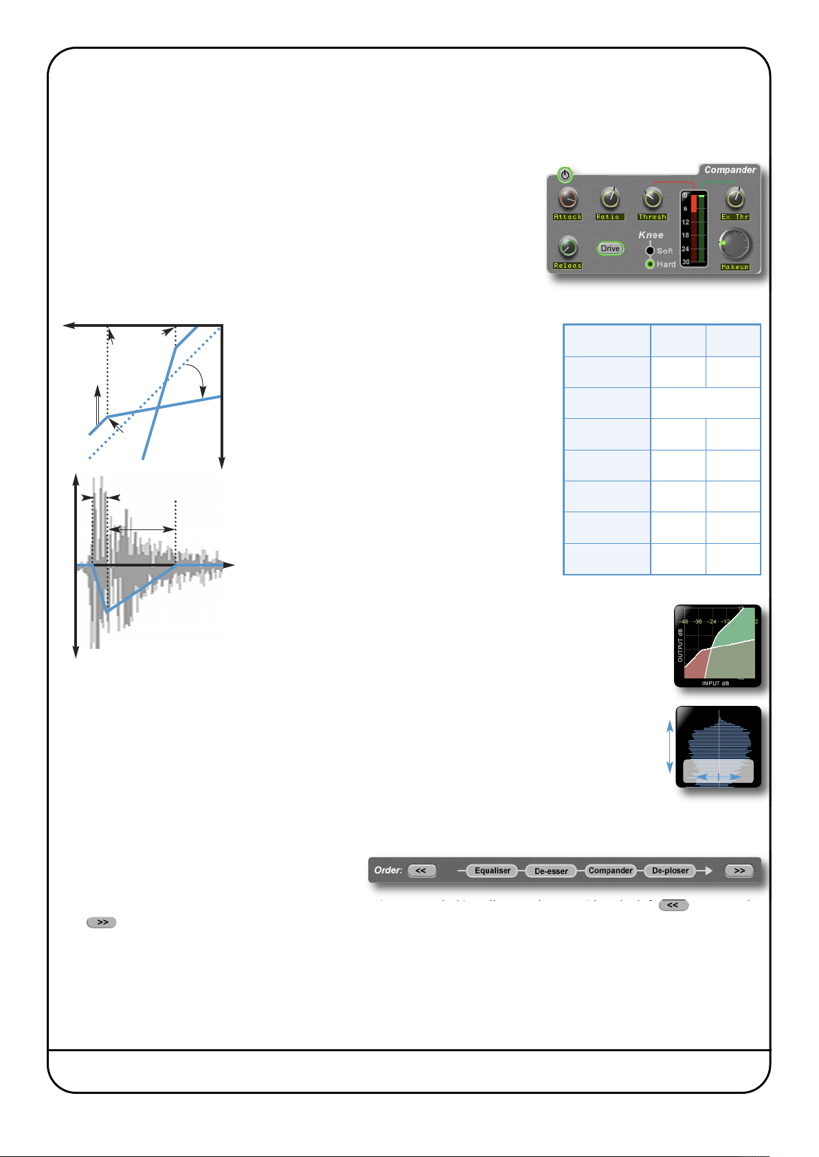
ompander
C
he Vocalstrip Compander is a hybrid Compressor and Expander. Switch it on by clicking on the power button in its top left-
T
and corner.
h
Expander
First the signal enters a fixed ratio downwards expander, designed to reduce room
ambience, spill or breath noise that is often brought up by the subsequent
compression.
To set the level at which the level reduction is introduced, turn the Ex Thr (Expander
Threshold), located on the Compander’s right-hand side. Turn the threshold to
minimum to turn the expander off. The amount of level reduction introduced is
shown in the green bar to the left of the Ex Thr knob.
input level
Make-up
Attack
full scale
Ex Thr
Thresh
(compress)
Ratio
Hard knee: sharp
Soft knee: curved
Compressor
The compressor offers both hard and soft knee
modes alongside fully variable Ratio, Thresh
(threshold), Attack, Releas (release) and
Makeup controls, along with a choice of Hard or
Soft Knee.
The output stage which is sourced after the
make-up gain features an optional Drivefeature,
output level
which introduces harmonic characteristics to the
signal. Its intensity is increase with the Makeup
gain. If you use a lot of make-up gain to drive the
Parameter Min Max
Ex Thr –96dB 0dB
Ex Ratio Fixed: 1.5:1
Comp Thr –48dB 0dB
Comp Ratio 1:1 50:1
Attack 0.1ms 100ms
circuit, the level can be reduced again using the
Release
Output level control. The amount of level
Release 0.5ms 2s
reduction introduced is shown in the red bar to
the right of the compressor controls.
Makeup 0dB 48dB
time
Compander Display
When any controls within the Compander section are moved, the
change in 0utput level
display in the top right-hand quarter of the window shows two
different graphs:
The left-hand graph is a gain-law display, showing the relationship between input and output levels,
as illustrated in the graph above-left.
The right-hand graph is an IO difference display, showing how often each level occurs within the input
0dB
and output signals. The input is shown on the left and the output on the right.
The vertical scale is amplitude, with 0dB at the top and –∞ at the bottom. The length of each line
Incidence
protruding from the centre represents the number of incidents of that amplitude over a period of
seconds.
–∞
Amplitute
Note that the FFT controls are for the EQ display, not the Compander display.
Processing Order
The processing order is controlled at the base of the
plug-in window.
To move a module within the order, highlight it so that it is surrounded in yellow, and press either the left arrow or the
right arrow.
Page 42 Duende Native User Guide
Page 49
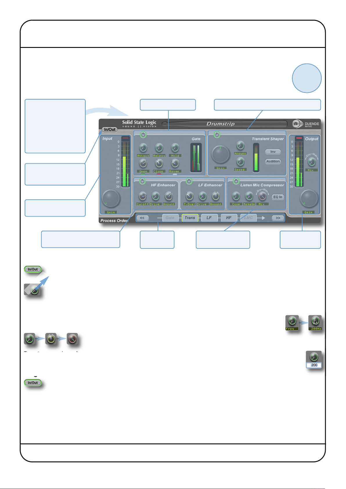
7. Drumstrip
INTRODUCTION
Drumstrip is a one stop solution for superior drum processing, providing tailor-made tools for fixing and
polishing your drum sounds. The illustration below introduces its features which are described in full over the
following pages. Click on the blue boxes to be taken to fuller descriptions of their contents. A good place to
start with Drumstrip may be the SSL on-line tutorials (See Page 5 for details).
?
click here for
on-line
tutorials
Above the main plug-in
window is a set of controls
which are specific to your
host application.
Please refer to your host
application’s user guide
for guidelines on using
these controls
Internal bypass for
smooth in/out
comparisons
Input level metering and
control
HF and LF Enhancers, for enriching
high and low frequencies
INTERFACE OVERVIEW
To press a switch in a plug-in, simply click on it. A green surround indicates that the switch is in its active state.
g
To turn a knob, click on it, and drag it up and to the right. If your mouse has a scroll wheel, you can also turn
Click + Dra
knobs by hovering over them and turning the scroll wheel.
To move any control slowly for fine adjustments, hold Shift on your keyboard whilst turning.
Gate for removing spill
Processing
order controls
Transient Shaper for increasing transient attack
Compressor with Listen
Mic characteristics
Output metering
and control
To reset a knob to its default value, click on it whilst holding Ctrl (Windows) or ⌘(Macintosh).
To view the value associated with a knob, hover over it with the mouse – the text box underneath the knob
will switch from displaying its parameter to displaying its value.
You may notice that the colour of the knob surrounds change to indicate their
level – green for low, yellow for mid, red for high.
To enter a precise value for any parameter, double-click on its value display, enter a value on your computer
keyboard, and press the
Return key.
Plug-in Bypass
The In/Out switch located above the Input section provides an internal plug-in bypass. This allows for smoother
In/Out comparisons by avoiding the latency issues associated with the host application’s Bypass function. The
button must be ‘lit’ for the compressor to be in circuit (as shown left).
Automation
Every plug-in parameter can be automated in host applications which support automation. The method for recording and
editing automation varies from host to host. For specific instructions on using automation within the host, consult the host
application documentation.
Duende Native User Guide Page 43
Page 50
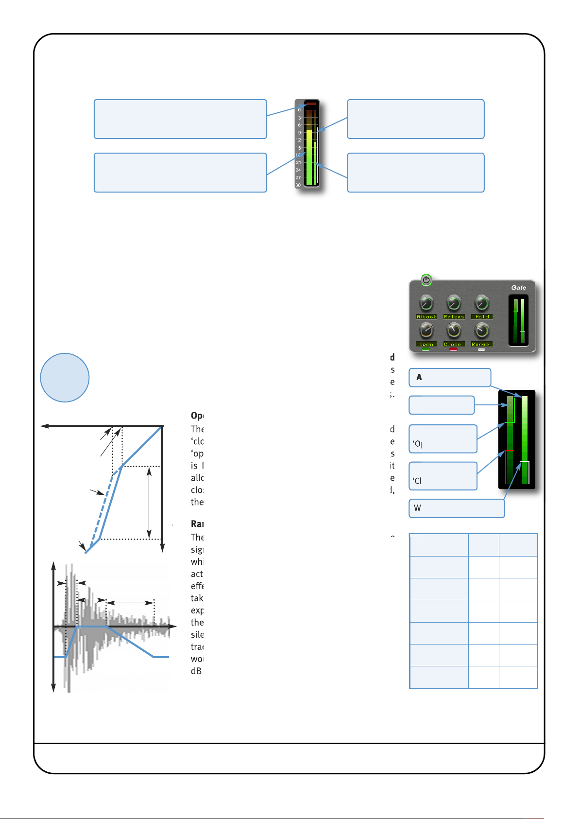
INPUT AND OUTPUT SECTIONS
he input and output sections at either side of the plug-in window provide input and output gain control, along with displays
T
f the following information:
o
Clip Light
Indicates that the signal is clipping. It clears
after 1 second, or click on it to clear manually.
Peak Meter
Allows you to observe the exact level
t any point in time.
a
The thin white bracket indicates
the signal’s recent dynamic range.
The thinner bar to the right shows
he RMS (average) level over time.
t
Range Meter
RMS Meter
In addition, the Output area provides a Mix control, for adjusting the mix between the processed (‘Wet’) signal and
unprocessed (‘Dry’) signal.
DRUMSTRIP MODULES
Gate
The gate is suitable for many applications, including:
• Shortening drum hits to obtain a ‘tighter’ sound
• Controlling ambience on live drums tracks
• Manipulating attack and decay characteristics
Switch the Gate on by clicking on the power button in its top left-hand corner.
?
click here for
on-line
tutorials
input level
Close Threshold
Open Threshold
Return path
via lower
threshold
1:1 ratio
above and
below range
Attack
change in 0utput level
The Gate provides controls for the Attack, Releas (release) and Hold
times, as well as Open and Close thresholds and Range levels, as
illustrated in the diagrams below left. If you are unclear about these
parameters, please refer to SSL’s on-line tutorials, introduced on Page 5.
full scale
Open and Close Thresholds
The levels for ‘opening’ the gate to audio and
‘closing’ it again are set separately. Generally, the
‘open’ level is set higher than the ‘close’ level. This
is known as hysteresis and is very useful as it
allows instruments to decay more naturally. If the
close threshold is higher than the open threshold,
the close threshold is ignored.
Range
Range
output level
The range is the depth of attenuation applied to the
signal when the gate is closed, as indicated by the
white line in the right hand column. For a true gating
action the range should be set to –80dB, which is
effectively silence. By reducing the range, the gate
takes on some of the characteristics of a downward
Hold
Release
expander where the signal is lowered in level set by
the range amount, rather than being completely
time
silenced. This can be useful in cleaning up a drum
track containing reverb, where silencing the reverb
would sound too artificial but attenuating it by a few
dB would push it down to an acceptable level.
Attenuation level
Input level
Green line:
‘Open’ threshold
Red line:
‘Close’ threshold
White line: Range value
Parameter Min Max
Open Thr 0dB –30dB
Close Thr 0dB –30dB
Range 0dB –80dB
Attack 0ms 0.1ms
Hold 0s 4s
Release 0s 1s
Page 44 Duende Native User Guide
Page 51
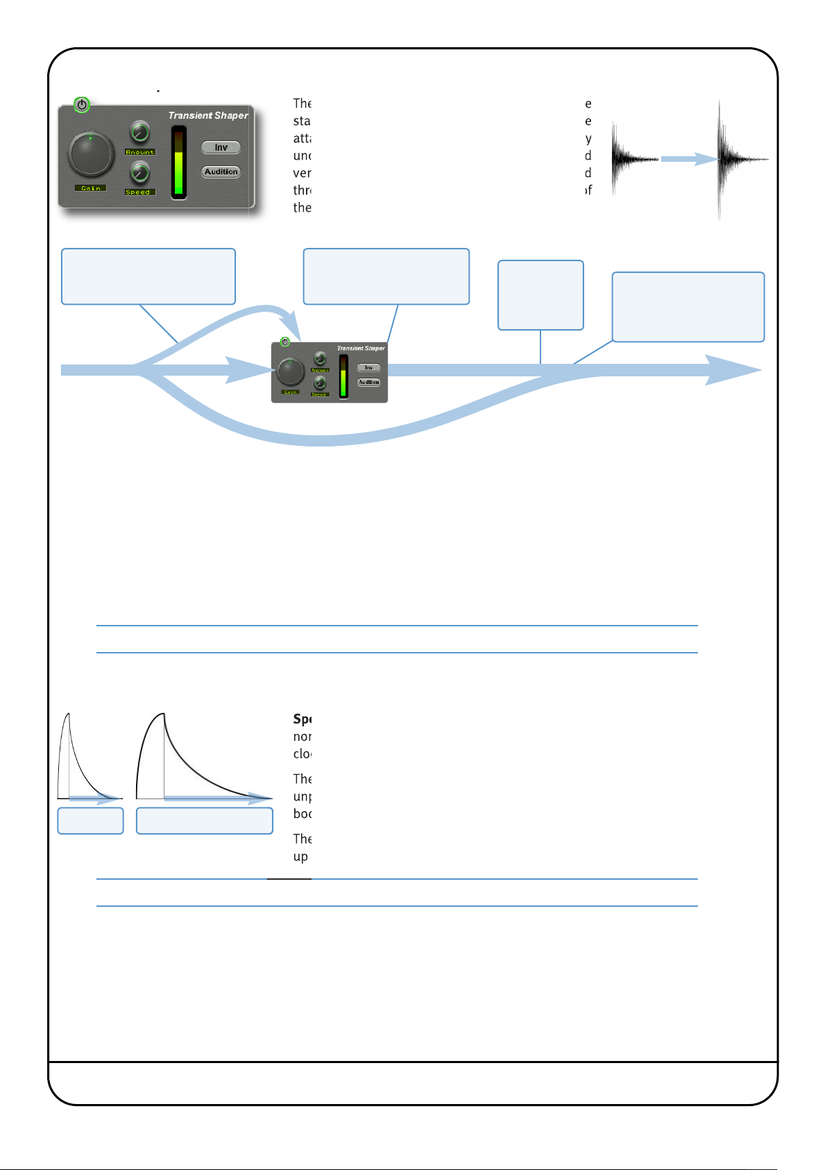
ransient Shaper
T
he Transient Shaper allows you to add attack to the
T
tart of a drum hit by increasing the amplitude of the
s
ttack portion of the signal whilst leaving the decay
a
nchanged. The right hand waveform is a processed
u
ersion of the one on the left. It has been passed
v
hrough the transient shaper where the amplitude of
t
he attack portion has been increased.
t
The Shaper uses a control
signal to detect transients. Gain
controls the level of this signal.
You can adjust the Speed of
the signal’s return to normal.
You can also Invert the signal
ress Audition
P
to listen to
processed
ignal
s
Processed signal is added
to unprocessed signal.
Amount controls how much
processed signal is added
Switch the Shaper on by clicking on the ‘power’ button in its top left-hand corner. The central meter gives visual feedback on
how much attack is being added using the Gain and Amount controls. If this rises to the top red section then reduce the
effect.
Gain controls the detection level of the controller signal, and should be set so that only the transients you want to shape are
detected. If this is set too low then the Shaper will do nothing; if it is set too high then the Shaper will detect too many
transients, resulting in an exaggerated process, and the attack appearing too long. The default setting of 0dB should be a good
starting point.
Note that Gain doesn’t directly affect the output signal’s gain.
Amount controls the amount of the processed signal added to the unprocessed signal. This process can increase the peak
level of a signal significantly so watch the output meter carefully.
Speed controls the length of time the added attack takes to fall back down to the
normal signal level once it has reached the top of the attack phase. Turn the knob
clockwise for a slower speed, and longer transient.
The Inv switch inverts the processed signal so that it is subtracted from the
unprocessed signal. This has the effect of softening the attack, resulting in more
Speed = 0 Speed = 1
body in the drum sound.
The Audition switch allows you to listen to the processed signal, to assist in the set
up process.
Note that when the Inv and Audition buttons are both pressed, the signal will not be inverted.
Duende Native User Guide Page 45
Page 52
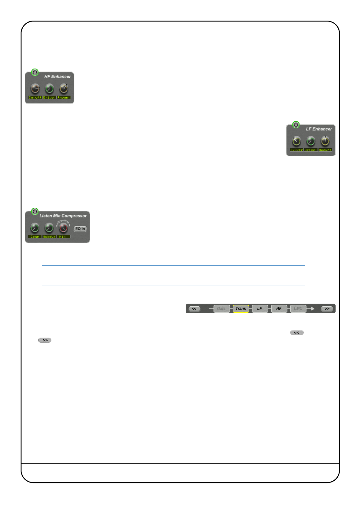
F and LF Enhancers
H
he HF and LF enhancers respectively enrich the high and low frequencies of the input signal. Whereas a standard EQ simply
T
aises the level of certain frequencies, the Enhancer adds a combination of 2nd and 3rd harmonics to those frequencies,
r
roducing a more pleasing effect.
p
Switch each Enhancer on by clicking on the power button in its top left-hand corner. No effect
is heard until an Enhancer’s Drive and Amount are turned up.
HF Cutoff sets the frequency above which the HF Enhancer generates harmonics. It ranges from
2kHz up to 20kHz – To add air or sparkle to a signal, push this frequency towards the higher end
of the range. To give more presence to a signal, use the lower end of the range. Note that the
effect is barely audible in the 15kHz to 20kHz range.
LF T.Over (turnover) sets the frequency below which the LF Enhancer generates harmonics. It ranges
from 20Hz up to 250Hz. The LF Enhancer is great for adding depth and weight to kick drums, snare or
toms.
Each Enhancer has its own Drive and Amount controls:
• Drive (or overdrive) controls the density and amount of harmonic content, from 0 to 100%.
• Amount is the amount of Enhanced signal that is mixed into the unprocessed signal, from 0 to 100%.
Listen Mic Compressor
The Listen Mic Compressor was first found in the classic SL 4000 E Series console. The Drumstrip edition includes a narrowband EQ by-pass and a wet/dry Mix control.
Comp controls the amount of compression, from 0 to 100%.
MakeUp controls the level compensation for the gain reduction and Mix controls the balance
of the compressed (‘Wet’) to uncompressed (‘Dry’) signal. Note that MakeUp only acts on the
‘wet’ part of the signal.
To simulate the original narrow-band listen mic characteristic, activate the EQ In button – to
use the compressor on the full frequency range, leave EQ In deactivated.
Note that Listen Mic Compressor features very quick fixed time constants. This means it is easily capable
of producing distortion on low frequency material.
Processing Order
The five processing blocks in Drumstrip can be configured in
any order, as defined by the Process Order blocks at the base
of the plug-in window.
To move a module within the order, highlight it so that it is surrounded in yellow, and press either the left arrow or the
right arrow.
Typically, the gate is first in the chain so that it is able to act on the full dynamic range of the signal before the signal is
processed by the Listen Mic Compressor.
Page 46 Duende Native User Guide
Page 53
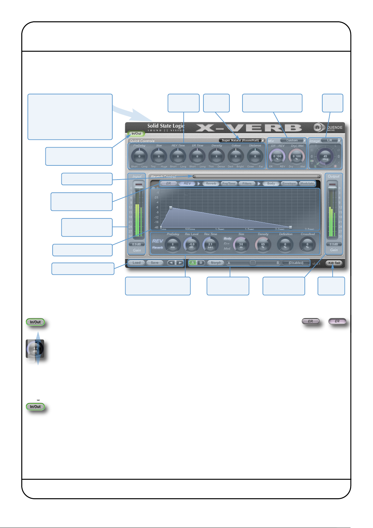
8. X-Verb
X-Verb is a versatile and comprehensive studio grade reverberation plug-in which delivers the density, warmth, depth and
stunning detail usually only found in top-end hardware reverb processors. The primary parameters provide conventional
reverb manipulation, while nearly 100 detail parameters allow an exceptional level of fine-tuning. Click on the blue boxes to
be taken to fuller descriptions of their contents.
Above the main plug-in window is
a set of controls which are specific
to your host application.
Please refer to your host
application’s user guide for
guidelines on using these controls
nternal bypass for smooth
I
in/out comparisons
Scroll/Zoom display
Select parameter set for
display and fine controls
Input level metering
and control
Interactive reverb graph
Create and select presets
Edit primary
parameters
Select
lgorithm
A
Adjust Early Reflections,
Reverb and Dry mix
Adjust
Image
Fine controls for adjusting
selected paramters
Compare or mix
A and B settings
Output metering
and control
Silence
reverb tail
INTERFACE OVERVIEW
To press a switch in a plug-in, simply click on it. The active state is sometimes indicated by a
green surround (shown left), and sometimes indicated by a shadow at the top rather than
the bottom, (shown right).
To turn a knob, click on it, and drag it up or down. If your mouse has a scroll wheel, you can also turn knobs by
Click + Drag
To move any control slowly for fine adjustments, hold
hovering over them and turning the scroll wheel. The value for each parameter is displayed in the centre of the
knob.
Shift on your keyboard whilst turning. To reset a knob to its default value,
click on it whilst holding Ctrl (Windows) or ⌘(Macintosh).
Plug-in Bypass
The In/Out switch located above the Input section provides an internal plug-in bypass. This allows for smoother
In/Out comparisons by avoiding the latency issues associated with the host application’s Bypass function. The
button must be ‘lit’ for the compressor to be in circuit (as shown left).
Automation
Every plug-in parameter can be automated in host applications which support automation. The method for recording and
editing automation varies from host to host. For specific instructions on using automation within the host, consult the host
application documentation.
inactive active
Duende Native User Guide Page 47
Page 54
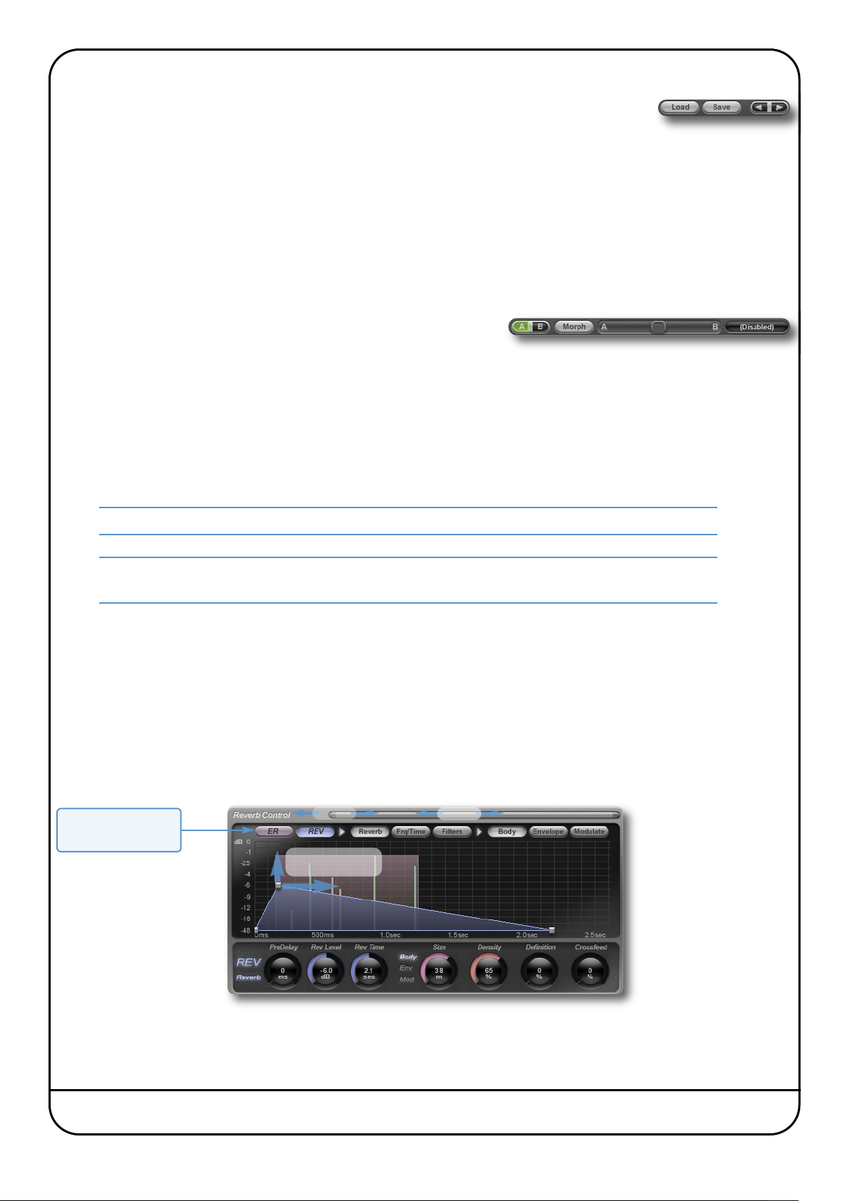
resets
P
he Load and Save buttons at the base of the screen provide quick access to the host application’s
T
mport and Save Settings functions. The arrow buttons to the right of the Load and Save buttons
I
an be used to cycle through all of the stored presets within the same folder.
c
For specific instructions on using presets within the host, consult the host application documentation. Presets use a standard
file format which allows them to be moved between a variety of platforms and host applications.
A file of ready-made X-verb presets are included in the plug-in installation. These provide starting points for a variety of
instruments and effects. To load SSL presets, click on the Load button and navigate as follows:
Macintosh:
indows:
W
/Applications/Solid State Logic/Presets/x-verb
:\program files\solid state logic\presets\x-verb
c
A-B Comparisons and Morphing
The A B button at the base of the screen allows you to load two
completely independent set ups and compare them quickly. When the
plug-in is opened, setting A is selected by default, as shown right. Pressing the A B button will switch between setting A and
setting B.
It is also possible to mix between the settings: Press the Morph button to the right of the A B button and use the slider to its
right to morph between A and B. The display to the right of the slider displays ‘(Disabled)‘ when Morph is off, and displays
the A to B ratio when Morph is on.
Every parameter is morphed with the exception of the Algorithm and the Size, which are taken from whichever setup is
indicated as active in the A B button.
Note that the Morph function is automatically deactivated when a parameter is moved.
Note also that automating Morphs will result in unpleasant artefacts if any time constants are different
between setups A and B
The Graph Display
The graph in the centre of the plug-in window displays the impact of the settings currently selected in the controls above and
below it. The row of buttons immediately above the graph (with ER [Early Reflections] and REV [Reverb] at their left-hand
end) determine what information is displayed, and also which controls appear beneath the graph.
The bar to the right of the Reverb Control label can be used to scroll and zoom the graph’s time axis: click and drag the
handles on either end of the scroll bar to zoom in and out, or click and drag the main scrollbar to scroll left or right. The graph
also auto-zooms to ensure that all of the important information remains visible.
The graph is interactive: move the grey nodes to adjust their associated parameters.
These buttons define
contents of display
The parameters displayed in the graph are described on Page 60.
Page 48 Duende Native User Guide
Zoom
Move nodes to
adjust values
Scroll
Page 55
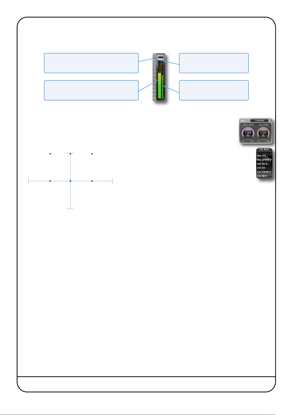
nput and Output Levels
I
he input and output sections at either side of the plug-in window provide input and output gain control, along with level
T
etering and clip lights:
m
Clip Light
Indicates that the signal is clipping. It clears
after 1 second, or click on it to clear manually.
Peak Meter
Displays the signal level. Input meter is pre-input
fader, Output fader is post-outputdaer
Move the semi-transparent bar up
The thinner bar to the right shows
the RMS (average) level over time.
Level Controller
and down to control the level
RMS Meter
Mix Levels
The Mix area towards the top right-hand corner of the display controls the mix between Early Reflections
(ER) and reverb (REV), as well as the mix between the un-processed (Dry) and processed (Wet) signals.
A number of presets are available – click on the box to the right of the Mix label and select one from the
drop-down menu.
Wet
Bus REVBus ER/REVBus ER
CH REVCH ER/REVCH ER
100% REV100% ER
The Bus and CH prefixes indicate the Dry – Wet mix:
Bus presets have a 100% Wet mix, for when X-Verb
is being used in an auxiliary bus where it has an
independent level control.
CH presets default to a 50-50 mix. Use CH when
X-Verb is being used within a track, and you need to
mix a smaller amount of the reverb signal with the
original.
Dry
In the ER/REV presets, both ER and REV signals are
at full. In the ER presets, the level of the REV signal
is halved, and in the REV presets, the level of the ER
signal is halved.
Duende Native User Guide Page 49
Page 56
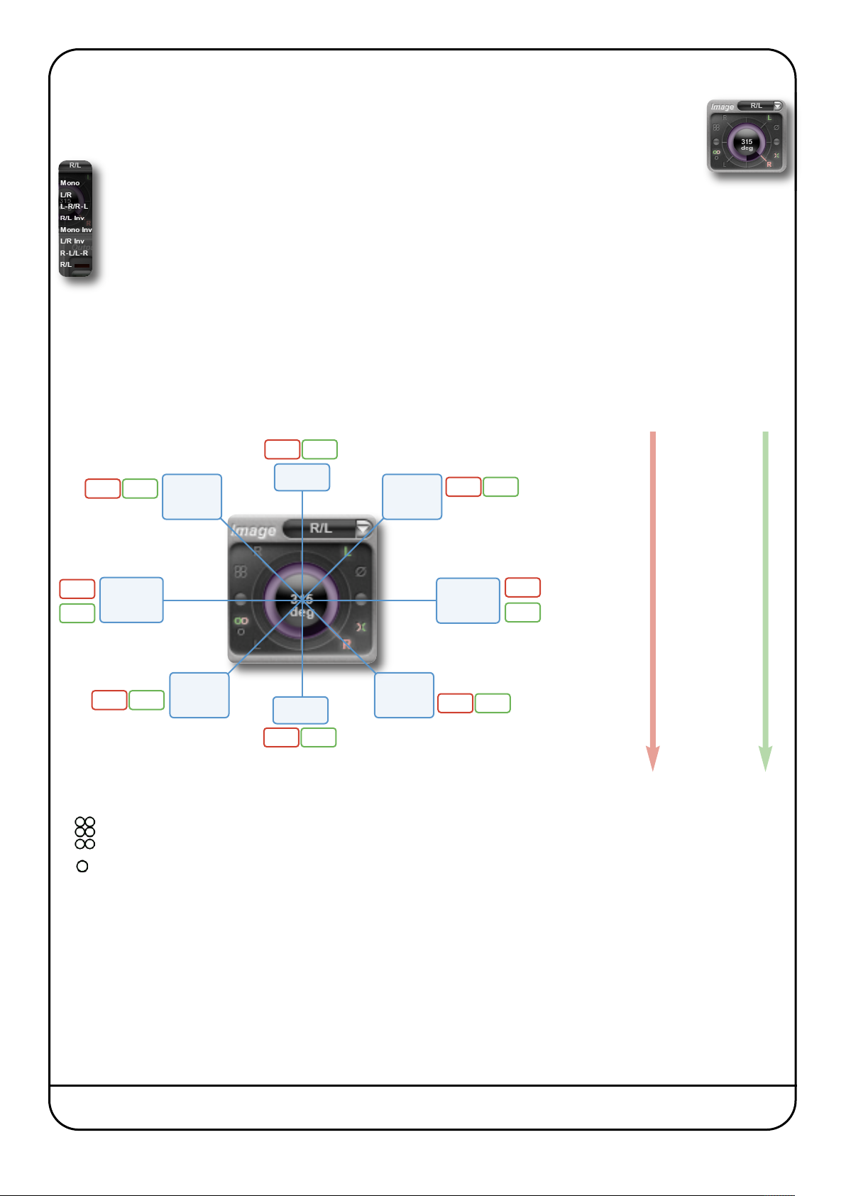
mage Control
I
-Verb comes with an innovative Stereo Image interface which performs Stereo width, Phase, Left/Right
X
hannel swapping, and Surround Processor compatible L-R – R-L operations. The control is located in the top
c
ight-hand corner of the window.
r
The image can be rotated by 360° in either direction. A number of image presets are included – click
on the box to the right of the Image label and select one from the drop-down list which appears
(shown left).
Note that the angle of the Image controller is not the position of the signal within the spectrum. In
essence, the display works as follows:
As the Image controller moves left, the level of the Left signal is reduced in the Right component,
and vice versa. As the image moves up, the level of the Left signal in the Left component is reduced, as is the level
of the Right signal in the Right component.
The diagram below illustrates the ‘angle’ associated with each preset, and the subsequent stereo/surround imaging. The blue
boxes indicate the stereo image, the red and green boxes indicate the actual signals on the left and right channels
respectively, and the image preset name is shown in bold. The diagram to the right indicates what is happening as you turn
the image controller clockwise.
Left stem Right stem
-R-L -L-R
0 L+R R+L
less R less L
-R -L
Stereo
L/R swap
R/L Inv
Mono
Mono Inv
Stereo
Normal
L/R Inv
-L -R
45 LR
less R less L
90 L-R R-L
less L less R
135 -R -L
L-R
R-L
Surround
Normal
L-R / R-L
R-L / L-R
Surround
L/R Swap
-L+R
-R+L
less L less R
180 -L-R -R-L
more R more L
225 -L -R
more R more L
270 -L+R -R+L
more L more R
315 RL
more L more R
L R
L/R
Stereo
Normal
Mono
Mono
L+R R+L
R/L
Stereo
L/R swap
R L
360 L+R L+R
The symbols surrounding the image control indicate the following:
Surround image
Stereo image
Mono image
Note that often two of these symbols will be ‘lit’, as the image moves between them.
X
L/R swap
L/R L and R symbols represent the phase of the left and right signals in the left component: The lower ones indicate
when that component of the signal is in phase, and the upper ones indicate when it out of phase. In other words,
the signals are in phase with each other when they are in the same row, and out of phase when they are in the
same column.
Ø Signals are more out-of-phase than in-phase
Page 50 Duende Native User Guide
Page 57
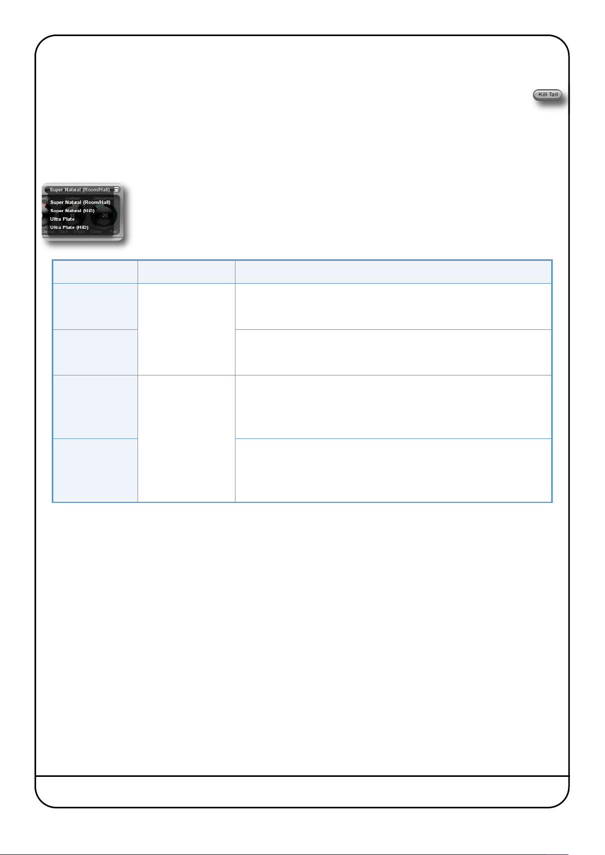
X-VERB CONFIGURATION
Kill Tail Button
Whenever you are auditioning changes in your configuration, and don’t want to wait for the reverb tail to die away
completely, click on the Kill Tail button in the bottom right-hand corner of the window.
1. Select an Algorithm or Preset.
It is often a good idea to begin setting up your reverb by loading a preset as a starting point as described on the previous page.
When starting from scratch, the algorithm on which you are going to build the reverb needs to be selected first: click on the
algorithm box, located top-centre in the plug-in window, and select an algorithm from the drop-down list which appears.
When algorithms are changed, other current settings remain as they were, making it easy to compare
similar settings with different algorithms, though some parameters may change their behaviour or
range. Bear in mind that changing the algorithm may lead to a short audio interruption.
Here is an overview of each algorithm:
ALGORITHM SUGGESTED USES DESCRIPTION
Super Natural
Super Natural HiD
Ultra Plate
Ultra Plate HiD
Rooms and Halls
Plates,
Larger Rooms
Produces real sounding rooms and halls of any size, with a rich diffusion
and natural sounding reverb envelope.
Produces higher density diffusion and refraction, for even more natural
and smooth sounding spaces.
A rich, silky, warm reverb, providing a more traditional sound with mainly
static and predictable refraction and diffusion. Ideal for making
instruments and vocals stand out in a mix, and for sound designers and
film composers who need huge reverbs.
Adds more density, shine and depth, somewhere between digital
reverberation and a real room.
Duende Native User Guide Page 51
Page 58

. Adjust the Primary Parameters
2
he seven controls across the top left of the plug-in window provide
T
ccess to the primary reverb parameters. Each of these parameters
a
epresent an interaction between a number of more detailed
r
arameters which can also be adjusted (see next page).
p
The following table explains what each primary parameter does, and what detail parameters are linked to it:
PARAMETER DESCRIPTION LINKED PARAMETERS
PreDelay
(Short-Long)
Size
(Tiny-Huge)
REV Time
(Short-Long)
ER Time
(Short-Long)
Density
(Thin-Dense)
Colour
(Dark-Bright)
Controls delay before reverb is heard, emulating the time
it takes for the sound to bounce back from the closest
walls.
Emulates the size of the room, altering the quantity and
speed of the reflections.
The time it takes for the reverb to die away.
The speed of the early reflections. These are the
reflections which bounce back early enough to be heard
individually. Reflections quickly become too dense to be
separated, at which point they become ‘reverb’.
The level of focus and definition in the reflections. The
more dense, the harder it is to discern individualy
reflections.
Alters the harmonic colour of the reflections, to emulate
the materials the sound might be bouncing off.
ER Master Delay
REV PreDel
Size
ER MasterTime
ER Tap Rebound
REV Time
REV Shape
REV PreDel
ER Master Time
ER Master Delay
Density
Definition
Attack
9 linked parameters, including:
ER Tap Filters,
REV Shelve Filters and Freq Times
Distance
(Close-Far)
Page 52 Duende Native User Guide
Emulates the distance between the sound and the listener.
ER Time, Delay and Level Masters;
REV PreDel, Master Level, Definition,
Density, Shape, Attack and Mode
Page 59

. Adjust the Detail Parameters
3
etail parameters are adjusted in the Reverb Control area of the window, located between the Input and Output areas. The
D
R and REV buttons in the top left-hand corner of the display define whether the ER (Early Reflections) or REV (Reverb)
E
arameters, graphs and sub-menus are displayed.
p
ER
If ER is selected, the ER Master Del (delay), Master Lev (level) and Master Time knobs appear below the graph and to the left.
In addition, six buttons appear to the right of the ER button, labelled L1, L2, L3, R1, R2 and R3. These define which of the six
Left and Right early reflection ‘taps’ are being edited using the three further buttons which further to the right: Main, Mod
and Filter. By selecting one of these three buttons, the controls for their parameters appear below the graph and to the right.
The area between the ER controls and the Main, Mod or Filter controls indicate which ER ‘tap’ is being edited, and which set
of parameters are displayed to the right – the appropriate symbols light up.
The following diagram illustrates which controls are available when each button is selected. Each parameter is defined in the
table on Page 60. The table on Page 56 indicates which of these parameters are affected by the Primary parameters.
ER
Main controls
L1
L2
Delay, Level, Phase, Pan
ER
Master Controls
Master Del, Lev, Time Cho Rate, Cho Depth
L3
R1
R2
R3
When ER parameters are active, the graph displays the
ER Box in pink. This represents the loudest and longest
ER taps. Each tap (L1, L2, L3 and R1, R2, R3) has a
handle which can be clicked/dragged horizontally to
adjust the Delay time, or vertically to adjust the tap’s
Level. The stem beneath each node is coloured red for
left, or green for right.
The handle half way along the top of the ER Block
adjusts the Master Level (increasing/decreasing the
individual taps levels relatively), the handle half way
down the right side of the ER Block adjusts the Master
Time (increasing/decreasing the individual taps delays relatively).
ER
Mod controls
ER
Filter controls
ER Rebound, Cutoff Freq
While the ER Box is displayed, the REV triangle is always visible in the background. Clicking on the REV triangle will switch
the Reverb Control area to REV and the sub page to Reverb.
Duende Native User Guide Page 53
Page 60

REV
f REV is selected, three buttons appear to the right of the REV button, labelled Reverb, Frq/Time and Filters. When each of
I
hese is selected, their parameters appear below the graph.
t
When the Reverb button is selected, a further sub-menu appears to its right, labelled Body, Envelope and Modulate. By
selecting one of these three buttons, the controls for their parameters appear below the graph and to the right (the three lefthand parameters – PreDelay, Rev Level and Rev Time – are displayed whenever Reverb is active). The area between the
left-hand master Reverb controls and the Body, Envelope or Modulate controls indicate which set of parameters are displayed
to the right – the appropriate symbols light up.
The following diagram illustrates which controls are available when each button is selected. Each parameter is defined in the
table on Page 60. The table on Page 56 indicates which of these parameters are affected by the Primary parameters.
REV Reverb
Body controls
Size, Density, Definition, Crossfeed
REV Reverb
Env controls
Shape, Attack, Rev Mode
REV
Reverb
PreDelay, RevLevel, RevTime
REV Reverb
Mod controls
REV
ChoRate, ChoDepth, Lifelyness, Float’n
REV
Frq/Time
Low Time and XOver, Mid Time, High Time and XOver
REV
Filters
Freq, Shelve Gain and In/Out (Low and High)
Page 54 Duende Native User Guide
Page 61

When REV is selected, the graph display is dependent
on which sub-menu is active.
hen Reverb is selected, the REV Triangle is displayed.
W
he left handle on the bottom adjusts the reverb
T
redelay (horizontal), the handle on the top adjusts the
p
everb level (vertical) and the right bottom handle
r
hanges the reverb time.
c
The ER block is visible in the background and clicking
on it will switch the Reverb Control area to ER.
When Freq/Time or Filters is selected, the graph
changes to display the Frequency/Time blocks and
High/Low Shelving filter curves. Both graphs are
overlaid with the active graph being in focus (on top).
Inside the Frq/Time graph, the left handle allows the
low reverb time factor (vertical) and low crossover
frequency (horizontal) to be altered. The mid handle
adjusts the mid frequency time factor (vertical) and
the right handle changes the high reverb time factor
(vertical) and high crossover frequency (horizontal).
In the Filters sub page a graph is only displayed when
there is an active filter. Each filter has a handle to
adjust the frequency (horizontal) and cut slope
(vertical).
Duende Native User Guide Page 55
Page 62

DETAIL PARAMETER RANGES AND DESCRIPTIONS
ER Menu
Menu Parameter Range Description
ER Master Controls
Sub menus
for each Tap
Main
Modulate
Filters
Master Delay 0 - 1500ms
Master Level 0 - 400%
aster Time
M
Delay 0 - 2500ms Tap Delay
Level –∞ to 0dB Tap Level
Phase On or Off Inverts phase of tap
Pan
Cho Rate 0 - 4Hz
Cho Depth 0 - 100%
ER Rebound 0 - 100%
Cutoff Freq 25Hz - 24kHz
- 400%
0
–100 (L) to
+100 (R)
Adds a Pre-Delay to the whole ‘ER Block’ so all individual
Taps move to the right.
Adjusts the level of all Taps, counter-clockwise to decrease,
clockwise to increase all tap levels.
djusts the delay of all Taps, counter-clockwise to decrease,
A
clockwise to increase all delay times.
Places tap in stereo spectrum
Adds a Chorus to the Tap to thicken and blur the reflection. At
0.00Hz the Chorus is switched off.
Adjusts the modulation depth of the Chorus. At 0% the
Chorus is switched off.
Adds a modulated Feedback Loop to the delay line of a Tap to
create complexity inside the Reflection.
Adjusts the Cut off Frequency of a smooth Low Pass Filter to
dampen the reflection and the rebounds.
Page 56 Duende Native User Guide
Page 63

EV Menu
R
enu
M
Reverb Master Controls
Body
Reverb
sub menus
arameter
P
PreDelay 0 - 1500ms Adds a Pre-Delay to the reverb tail, moving the Triangle right.
Rev Level –∞ to 0dB Adjusts the level of the reverb tail
Rev Time Varies
Size 0 - 60m
Density 0 - 100%
Definition 0 - 100%
Crossfeed 0 - 100%
Shape 0 - 255
ange
R
escription
D
Determines the time for the reverb level to fall below 60dB
(RT 60). Dependant on the Size, Shape, Attack and Algorithm.
Adjusts room size by altering the reverb delay structure, the
diffusion engine and the complexity approximation.
IMPORTANT: Changing the Size can result in audible artefacts.
Adjusts the density in the diffusion and refraction engine and
complexity approximation. Higher values smoothen the reverb
tail and individual ‘refractions’ or ringing echoes disappear.
Adds defined and randomly modulated reflections to the
beginning of the reverb tail. Can add clarity but may reduce
density. In Ultra Plate, Definition also modulates the Density in
relation to Input Level to create a more natural decay.
X-Verb has separate diffusion engines for left and right. Crossfeed
introduces the left input to the right channel and vice versa,
reducing the stereo image but adding the impression of distance.
Alters the Shape of the Reverb Triangle. At higher values the
reverb build up phase (Attack) becomes longer, while the tail fade
out phase becomes shorter.
Envelope
Modulate
Freq/Time Controls
Filters Controls
Expands the time of the Attack. At higher values the reverb build
Attack 0 - 255
Rev Mode -9 to +9
Cho Rate 0-4Hz Adds Chorus to the tail to thicken and smoothen the reverb.
Cho Depth 0-100% Adjusts the modulation depth of the Chorus.
Lifelyness 0-48
Floatation 0-22ms
Time (Low,
Mid, High)
XOver
(Low, High)
Freq
Shelve Gain –∞ to 0dB Sets gain reduction for Low and High filters
0.1-4
25Hz 24kHz
25Hz 24kHz
up time can take up to 700 ms. Note that when Shape is set to 0,
Attack is inactive.
Allows less natural-sounding reverb. At 0, reverb sounds most
natural – positive values compress tail. LF energy may lead to
artifacts – lower Input level or set RevMode to 0 to eliminate.
Adds natural sounding random time modulation to refractions in
Diffusion engine. For Ultra Plate, adds modulation to Chorus
Determines the maximum range of ‘Lifelyness’ time fluctuation.
Not available in the Ultra Plate Algorithms.
Factor for the RevTime multiplier of each band. Turn clockwise to
lengthen. Since high frequencies have the least energy the HF
default factor is 0.2.
Adjusts the crossover frequency between Low and Mid bands,
and between Mid and High bands.
Sets filter frequency for Low and High filters
In/Out In/Out Switches each filter in and out of circuit.
Duende Native User Guide Page 57
Page 64

Blank page – well, nearly
Page 58 Duende Native User Guide
Page 65

Appendix: Cross-grade
It is easy to see that a customer who has previously invested in a hardware Duende DSP unit might want to continue to
benefit from ongoing support and development of new Duende plug-ins. In recognition of this SSL is offering every registered
Duende DSP owner a free ‘cross-grade’ to Duende Native. This page describes the terms and conditions for eligibility to a free
cross-grade, it describes what we are offering and how to go about applying for a cross-grade.
CROSS-GRADE ELIGIBILITY CONDITIONS
- If your hardware Duende DSP unit was registered in your Profile at the SSL web site on or before 1st November 2010 you
are eligible to claim free Duende Native licences equivalent to any Duende plug-ins you own for your Duende DSP unit.
- If you register a hardware Duende DSP unit which has not previously been registered with the SSL web site, you are eligible
to claim free Duende Native licences equivalent to any Duende plug-ins you own for your Duende DSP unit. There is no time
limit on this.
- If you own a hardware Duende DSP unit which had already been registered with the SSL web site on or before 1st November
2010 you will not be able to re-register it and will not be eligible for a free cross-grade.
- If you have bought any of the optional plug-ins (Drumstrip, Vocalstrip, X-Comp, X-EQ or X-Verb) for any model of hardware
Duende DSP unit or the Bus Compressor Upgrade for a Duende Mini, the Duende DSP unit will be eligible for a free cross-grade.
ADDITIONAL CONDITIONS
- By accepting the free cross-grade offer you agree that SSL will no longer support your hardware unit.
- If you sell your existing Duende hardware unit, the new owner will not be able to register it, or be eligible for support or
be eligible for a free cross-grade.
- The Duende Native copy protection system examines your computer and builds a unique profile of it. As part of the product
activation process this information is returned to the SSL Online Licence Centre to be used in the generation of a Product
Licence that is unique to your computer. By accepting these Terms & Conditions you agree to SSL examining your computer
system and holding information about it. If you are unwilling to have your computer profiled in this way you should not
install Duende Native. SSL does not examine any personal data, other software installed or any computer use behaviour.
SSL will not share any of your data with any third parties.
- Each Duende hardware unit and all associated plug-ins will be cross-graded as a ‘bundle’ in a single transaction. If the
Duende Native plug-ins created as part of the cross-grade are ‘deactivated’ at a later date they will all be deactivated as
a bundle.
- When you cross-grade a specific unit, you cross-grade the unit and all plug-ins associated with it. You cannot cross-grade
individual plug-ins separately. Note that you do not have to install all of the Duende Native plug-ins; during the installation
process you can choose which individual Duende Native plug-ins you wish to actually use.
WHO GETS WHAT?
Subject to eligibility and agreement to our Terms & Conditions a free cross-grade means:
- Duende Mini, Classic & PCIe units included the ‘EQ & Dynamics Channel’ plug-in as standard so owners of all eligible units
can claim a free ‘Duende Native Channel’ licence.
- Duende Classic and Duende PCIe units included the ‘Stereo Bus Compressor’ plug-in as standard so owners of all eligible
units can claim a free ‘Duende Native Bus Compressor’ licence.
- Owners of optional plug-ins (Drumstrip, Vocalstrip, X-EQ, X-Comp, X-Verb, Bus Compressor for Duende Mini) for eligible
units can claim a free Duende Native equivalent licence.
- If you bought one of our Studio or Expanded Packs and your unit is still eligible you can claim a Duende Native licence for
each of the plug-ins in your bundle.
- If you own more than one hardware Duende DSP unit, providing each individual unit is eligible, you get a free cross-grade
for each unit. If you have multiple optional plug-ins registered (ie. one for each hardware unit) you can claim a free
cross-grade for each registered instance of each optional plug-in. So if you own two PCIe units, with all 5 optional plugins registered for both units… and both units are eligible… you can claim two complete sets of Duende Native licences
- In short; everybody who owns an eligible Duende DSP unit gets an equivalent Duende Native plug-in pack 100% for free
and gets to keep their Duende DSP. Everybody who owns multiple eligible Duende units gets multiple plug-in packs.
Duende Native User Guide Page 59
Page 66

WHERE IS THE CATCH?
here isn’t one. We have changed our future development strategy and think it is the right and proper thing to do to provide
T
ur existing customers with an opportunity to benefit from future development. You are not obliged to switch, you can carry
o
n using your Duende DSP but you deserve the choice. It also feels good to reward customer loyalty.
o
FAQS
Can I run demo versions of the Duende Native plug-ins before I choose to cross-grade?
Yes you can. Everybody can get a free 30 day demo licence for each Duende Native plug-in. Note however that when you
choose to install the Native version of a Duende DSP plug-in that is already installed on your system, the Native plug-in will
overwrite the DSP version. You can perform a system roll back easily though if you wish as described below. Demos are
limited to one per host computer.
Will the new Native plug-ins load into my old projects and recognise my saved settings?
Yes. The Duende Native plug-ins appear to your system as ‘exactly’ the same plug-ins as your DSP versions… Your DAW sees
your Native plug-in as though it is your old DSP plug-in and loads the saved settings.
Can I use the Duende Native and Duende DSP versions of a plug-in at the same time?
The short answer is no you can’t… but you can use different Duende Native and Duende DSP plug-ins alongside each other
on a single system. When you run the Duende Native installer you are prompted to select which Native plug-ins you wish to
install. If you choose to install the Native version of a Duende DSP plug-in that is already installed on your system the Native
plug-in will overwrite the DSP version.
So can I run a hybrid system with some Duende Native and some Duende DSP plug-ins running side by side?
Yes you can. For users owning older, less powerful computers this may be a sensible approach to take. When you are installing
Duende Native simply choose to only install the plug-ins you wish to run as Native versions.
So my Duende hardware will continue to work even after I have cross-graded?
Yes it will. But as part of the Terms & Conditions of the cross-grade you must agree that, after the cross-grade, you relinquish
any warranty terms, your old hardware unit is not eligible for support or repairs, no new upgrades or plug-ins can be purchased
for it and while you can keep the unit for personal use, you will not give or sell the unit to a 3rd party.
Can I change my mind and go back to using my Duende DSP after going Native?
Yes you can. You would need to uninstall the Duende Native version and re-install the Duende DSP version. Note that the
Duende DSP installer overwrites all of the plug-ins to perform a complete system roll back. If you then wish to re-run the
Duende Native installer once again and select only the plug-ins you wish to run Natively you can.
So does that mean I can choose to only cross-grade some of my plug-ins?
No. When you cross-grade you cross-grade the individual hardware unit and all plug-ins associated with it. Although you can
then choose which of the Native plug-in versions to Install and Activate you must agree to cross-grade your unit as a bundle.
I have bought a Duende Mini DSP Upgrade or a Duende V3 64 or 128 Channel Upgrade… is that cross-graded too?
Duende Native has no channel count limits. How many plug-in instances you can run simultaneously on a single system is
limited only by the power of your computer. In recognition of your financial investment in channel count for your Duende we
are also offering, for a limited time, an additional reward offer to all owners of Channel Upgrades. If you have previously
purchased one of these upgrades we will contact you directly with details of this offer..
Can I move my Duende Native plug-ins from one computer to another?
You can only use Duende Native plug-ins on one computer at a time. If you use a software only ‘Virtual Dongle’ you cannot
easily move your Duende Native licences from one computer to another. If you need to move your licences because you are
changing computer or have suffered a catastrophic failure and need to completely re-build your computer, please contact
support@solidstatelogic.com. If you require licence portability; ie. you wish to install the software on multiple computers and
transfer your licence between them at will (eg. you have a desktop computer in your studio and a laptop you use when
travelling) then you should buy a Duende Native Hardware Dongle. The Duende Native Hardware Dongle enables full licence
portability across an unlimited number of computers. You may install the Duende Native plug-ins on as many computers as
you like and simply move your dongle to the machine you wish to work on. You can only buy one dongle per set of Duende
Native Licences; you cannot install a single licence on multiple dongles. The Duende Native Hardware Dongle is available
exclusively from the SSL online store.
Page 60 Duende Native User Guide
Page 67
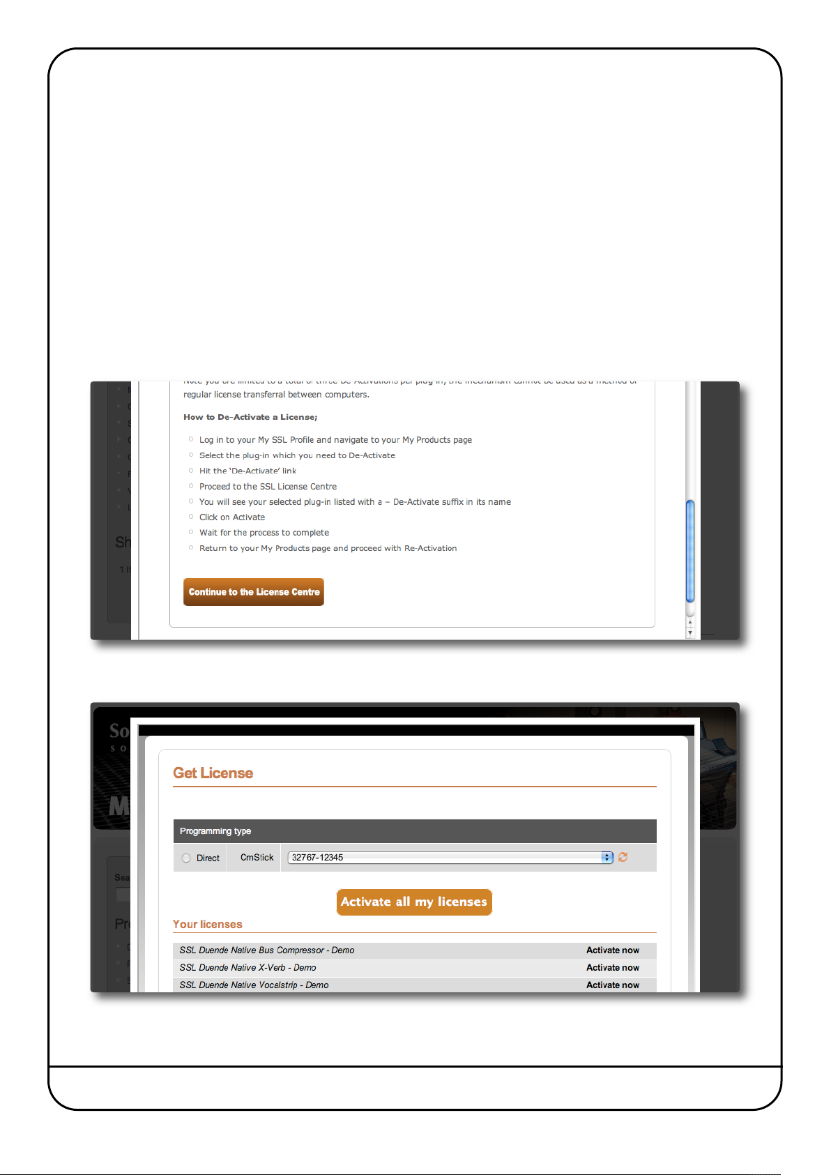
DUENDE NATIVE CROSS-GRADE INSTALLATION
lease follow the software download and installation instructions laid out in Section 1 of this manual.
P
Section 1 also includes information about registering on the SSL website, if you have not already done so. This is a necessary
part of the activation process.
Having logged into the website, go to the My Products tab, where all registered Duende hardware will be listed. If you need
to register a unit, use the registration section at the top of the screen.
Click on the Cross-grade label next to each Duende hardware unit, then confirm that you have read and agree to the terms
and conditions and are sure you wish to cross grade.
This will create a Duende Native Products section within your Product list, containing an item labelled Free Duende
Cross-grade – Unit #x (where x is the unit serial number), followed by a 32 character activation code. You will also see the
plug-ins included in the Upgrade listed.
Click on the Activate label beside the activation code and the SSL Online Licence Centre will open in a new web browser
window.
Read the instructions, then click where indicated at the bottom of the page:
A list of plug-ins will appear. Click on the individual Activate Now labels to complete the activation process. If you are ready
to activate all of the licences listed, click on Activate all my licences.
Duende Native User Guide Page 61
Page 68

Blank page – well, nearly
Page 62 Duende Native User Guide
Page 69

Index
A
A-B (Vocalstrip) 40
A-B (X-Comp) 28
A-B (X-EQ) 33
-B (X-Verb) 48
A
Analyse button (X-EQ) 33
Aud button (Vocalstrip) 40
Authorising Your Plug-ins 16
Automation (Channel Strip plug-in) 20
Automation (Drumstrip) 43
Automation (Vocalstrip) 40
Automation (X-Comp) 27
Automation (X-EQ) 32
Automation (X-Verb) 47
B
BELL (Channel Strip plug-in) 19
Bleed (X-Comp) 29
Bleed Graph (X-Comp) 30
Bypass (Drumstrip) 43
Bypass (Vocalstrip) 39
Bypass (X-Comp) 28
Bypass (X-EQ) 33
Bypass (X-Verb) 47
C
Channel Strip plug-in 19
Compander (Vocalstrip) 42
Compression Law Graph (X-Comp) 30
Compressor (Channel Strip plug-in) 22
Compressor (Vocalstrip) 42
Creating an SSL Profile 13
Cross-grade 59
D
De-esser (Vocalstrip) 40
De-ploser (Vocalstrip) 41
Display (Vocalstrip) 41, 42
Display (X-Comp) 30
Display (X-EQ) 31
Display (X-Verb) 48
Drum Strip 43
DYN IN (Channel Strip plug-in) 19
DYN S/C (Channel Strip plug-in) 19
Dynamics (Channel Strip plug-in) 22
E
E switch (Channel Strip plug-in) 21
EQ & Dynamics Channel Strip 19
EQ History 37
Q IN switch (Channel Strip plug-in) 21
E
EQ Shapes (X-EQ) 35
Equaliser (Channel Strip plug-in) 21
Equaliser (Vocalstrip) 41
ER (X-Verb) 53, 56
EXP button (Channel Strip plug-in) 19, 22
Expander (Channel Strip plug-in) 22
Expander (Vocalstrip) 42
F
FAQ 1
FAST ATT (Channel Strip plug-in) 19, 22
Filter (Channel Strip plug-in) 20
Filter Shapes (X-EQ) 36
G
Gate (Channel Strip plug-in) 22
Gate (Drumstrip) 44
GR History (X-Comp) 30
H
HF Enhancer 46
I
I/O Diff Graph (X-Comp) 30
Image (X-Verb) 50
Input (Channel Strip plug-in) 20
Input (Drumstrip) 44
Input (Vocalstrip) 40
Input (X-Comp) 30
Input (X-EQ) 32
Input (X-Verb) 49
K
Kill Tail Button 51
Knee (X-Comp) 28
L
LF Enhancer 46
Limiter (Channel Strip plug-in) 22
Listen Mic Compressor 46
Duende Native User Guide Page 63
Page 70

M
ax GR (X-Comp) 28
M
Mix (X-Verb) 49
Morph button 48
O
Output (Channel Strip plug-in) 23
Output (Drumstrip) 44
utput (Vocalstrip) 40
O
Output (X-Comp) 30
Output (X-EQ) 32
Output (X-Verb) 49
P
Parallel button (X-EQ) 34
Parameters (X-Verb) 53, 56
PK button (Channel Strip plug-in) 19, 22
PRE EQ switch (Channel Strip plug-in) 22, 23
Presets (Vocalstrip) 40
Presets (X-Comp) 28
Presets (X-EQ) 33
Presets (X-Verb) 48
Primary Parameters (X-Verb) 52
Processing Order (Channel Strip plug-in) 23
Processing Order (Drumstrip) 46
Processing Order (Vocalstrip) 42
Profile 13
X
-Comp 27
X
X-EQ 31
X-Verb 47
R
REV (X-Verb) 54, 57
RMS (Channel Strip plug-in) 22
S
S/C LISTEN (Channel Strip plug-in) 19, 23
Side Chain (Channel Strip plug-in) 23
SSL profile 13
Stereo Bus Compressor 25
Support 1
T
Transient Shaper (Drumstrip) 45
Tutorials 1
V
Vocal Strip 39
Page 64 Duende Native User Guide
Page 71

Notes
Duende Native User Guide Page 65
Page 72

www.solidstatelogic.com
Visit SSL at: www.solidstatelogic.com
82BDNM01A
© Solid State Logic
All Rights reserved under International and Pan-American Copyright Conventions
Duende, Duende Native, Drumstrip, Vocalstrip, X-Comp, X-EQ, and X-Verb
are trademarks of Solid State Logic
All other product names and trademarks are the property of their respective owners and are hereby
acknowledged
No part of this publication may be reproduced in any form or by any means, whether mechanical or
electronic, without the written permission of Solid State Logic, Oxford, OX5 1RU, England
As research and development is a continual process, Solid State Logic reserves the right to change the
features and specifications described herein without notice or obligation.
Solid State Logic cannot be held responsible for any loss or damage arising directly or indirectly from
any error or omission in this manual.
E&OE
 Loading...