

Page 1
www.solidstatelogic.com
Nucleus
User Guide
2
Nucleus2. This is SSL.
Page 2

Document History
82BN0M01C September 2016 Initial Release
82BN0M01D October 2016 Minor changes
Page 3

Table of Contents
Introduction 1
2
ucleus
N
How to use this Manual 2
. Nucleus
1
Channel Strip and Mode Switches 3
Centre Section and Analogue Control 4
Nucleus
2. Nucleus
3. Software Installation 9
1
onventions 2
C
lossary 2
G
oftware Versions 2
S
elp! 2
H
2
verview 3
O
2
Remote 4
2
Configurations 5
DAWs With Proprietary Soundcards 5
DAWs Without Proprietary Soundcards 7
Multiple DAWs 8
Software Installation – Mac 9
Software Installation – Windows 10
4. Connection and Software Configuration 13
Physical Connections 13
Audio Connections 13
Data Connections 13
Configuring Network Connections 14
Network Wiring 14
2
Assigning the Nucleus
IP Address 14
Direct Network Connection Configuration (Mac) 15
Wider Network Connection Configuration (Mac) 15
Direct Network Connection Configuration (Windows) 15
Wider Network Connection Configuration (Windows) 15
Connecting Nucleus2to Multiple Computers 16
ipMIDI Configuration 17
MIDI Port Mapping 17
Pro Tools 17
Logic Pro 18
Dante Soundcard Configuration 19
Setup 19
Sample rate 20
Stand-alone System vs Wider Dante Network 20
SPDIF I/O & External Soundcard 20
5. Nucleus
2
Remote 21
Establishing the Remote Connection 21
Remote Tabs 22
The DAW Tab 22
The Network Setup Tab 22
The About Tab 22
Remote Layer Selection 23
Nucleus2User Guide Page III
Page 4

Layer Profile Configuration 23
rotocols 23
P
reating Profiles – Method 1 23
C
reating Profiles – Method 2 24
C
electing a Profile 24
S
anaging Profiles 25
M
Timeline Functions 26
Transport Master 26
Jog Wheel Function 26
Automation Display (HUI Only) 26
oft Key Configuration 27
S
Default Soft Keys 27
User 1, User 2 Soft Keys 27
Transport / Utility Soft Keys 28
Assigning Soft Key Functions 28
DAW Protocol Commands 29
DAW Keyboard Shortcuts 30
Soft Key Menus 31
Renaming Softkey Assignments 32
Assigning Modified Functions to Soft Keys 32
Removing and Replacing Soft Key Assignments 32
Configuring Continuous Controller Layers 33
6. DAW Operations 35
Layer Select 35
Soft Keys 35
Channel Control 36
Channel Scrolling 36
Basic Channel Parameters 36
Channel Metering 36
Track Arming 36
Automation Control 36
V-Pot and V-Sel Control 37
Plug-in Control (Pro Tools Only) 38
Master Control 39
Basic Transport 39
Navigation Controls 39
Additional Master Controls 39
MODE Display (MCU Only) 39
User Keys 40
7. Analogue Operations 41
Recording Sources 41
Monitoring 41
Talkback 42
Metering 42
Appendix 43
Transport/Utility Function Map 43
DAW Protocol Command Soft Key Labelling 44
Pro Tools 44
Logic 45
Nuendo 46
Index 47
Page IV Nucleus2User Guide
Page 5
Introduction
Nucleus
Welcome to Nucleus2, SSL’s integrated DAW controller and soundcard for the Dante audio-over-IP network. Nucleus
allows you to record audio and monitor your studio software through SSL’s legendary analogue circuitry and converters,
while placing full control of your session underneath your fingertips. While the basic configurations created by SSL’s studio
engineers allow you to get working with Nucleus2 straight out of the box, the functions assigned to much of the control
surface can be adapted to suit the specifics of your working environment, as configured within the Nucleus2 Logictivity
Remote software.
2
2
DAW Control Principles
A DAW controller is part mixing console and part computer keyboard. It is a mixing console insofar as it uses channel
strips and faders etc. to mix and manipulate audio. It is a computer keyboard insofar as, rather than affecting any audio
electronics within it, it simply sends (and receives) commands to a computer program.
Of course, Nucleus2’s two analogue channels makes it more than a DAW controller.
Nucleus2 can be used to control DAW software using either HUI or MCU protocols. These are the standardised control
‘languages’ used by the majority of DAW software on the market today: HUI is used by ProTools, MCU by Logic and Nuendo.
Please refer to your DAW software’s user guide if you are unclear which protocol you use.
The Nucleus
‘command’,
connections to control DAW sessions: ipMIDI (a conventional MIDI signal, sent over Ethernet) for HUI or MCU control, and
USB for standard keyboard commands.
Using Nucleus
controlled at one time.
Because each DAW is different and the precise application of HUI and MCU protocols is specific to the DAW software being
used, this manual does not provide detailed descriptions of specific DAW operations. Please refer to your DAW User Guide
for information about how to apply the control offered by Nucleus
2
control surface also replicates a number of computer keyboard keys, such as modifiers (
<Ctrl>, <Alt>
2
’s Layer structure, different DAW programs can be connected simultaneously, although only one can be
),
<Enter>
and
<Esc>
keys, and shortcuts such as ‘Save’ and ‘Undo’. Nucleus2 uses two
2
.
<Shift>
, ⌘ or
Nucleus2 User Guide Page 1
Page 6

HOW TO USE THIS MANUAL
fter this introduction, you will find a quick overview of Nucleus
A
se of the Nucleus
u
onventions
C
2
ogictivity Remote, and general Nucleus
L
Throughout this manual, the following conventions will be used:
2
• Labels found on the Nucleus
control surface are indicated in capitals LIKE THIS.
• Labels and text shown in the Nucleus2 Remote or other computer dialogues are indicated in bold Like This.
The few instances where we refer directly to computer filenames etc. will be shown Like This
•
Where necessary, DAW computer keyboard key strokes will be shown like thiswhilst function keys (as opposed to
•
normal numbers, symbols and characters) such as the ‘Control’ key will be shown with ‘angle’ brackets such as
• Where DAW protocol commands appear, the command or function will be shown with ‘curly’ brackets {
Notes and additional information appear like this.
• The Nucleus
• The Nucleus
2
Logictivity Remote app will in some cases be abbreviated to just ‘Remote’.
2
itself may be refered to either by name, as the ‘DAW controller’ or as the ‘control surface’.
Please be aware that screenshots shown may differ slightly in appearance from their on-screen equivalents.
Glossary
The following terms are either concerned with general DAW control, or specific Nucleus2 operations:
2
followed by more detailed sections covering installation,
,
2
peration.
o
.
like_this}
<Ctrl>
.
.
CC Layer A Continuous Controller (‘CC’) Profile for use with MIDI devices.
Dante Digital Audio Network Through Ethernet. A combination of software, hardware, and network protocols that
deliver uncompressed, multi-channel, low-latency digital audio over a standard Ethernet network.
DAW Digital Audio Workstation. Software which emulates a recording studio, such as ProTools, Logic and Nuendo.
ipMIDI MIDI control data sent over Ethernet.
HUI Human User Interface. The DAW control protocol used by ProTools and others.
Layers Different DAW programmes, one of which can be controlled by Nucleus
2
at a time, though all transports can
be activated simultaneously from one transport master.
MCU Mackie Control Unit. The DAW control protocol used by Logic, Nuendo and others.
2
SD Card An SD memory card fitted to the rear of Nucleus
for Profile storage.
Soft Keys Many switches on Nucleus2 can be programmed through the Nucleus2 Remote to perform DAW specific
functions. These switches are grouped together as ‘soft key sets’.
USER The USER and USER switches located in the centre section area of Nucleus2 are used to apply soft key
sets to the switches above and below the scribble strip displays.
V-Pot In-channel rotary encoder used to control a variety of parameters. The V-Pot is located below the digital display.
V-Sel In-channel encoder switch, used to control a variety of parameters, often associated with the V-Pot. The switch
is activated by pressing the V-Pot. Note that the VSEL switch is different from the channel select (SEL) switch.
Software Versions
The information in this manual is correct for Nucleus
2
software V2.0/1 or greater, Nucleus2 firmware V2.0/0 or greater
and Nucleus2 Browser V2.0/0 or greater.
Help!
2
Should you require assistance with Nucleus
that is not addressed by this manual, please refer to the Support pages of
the SSL Website at www.solidstatelogic.com/support/Nucleus2 and click on ‘Ask a Question’ to get in contact with us.
Page 2 Nucleus2 User Guide
Page 7
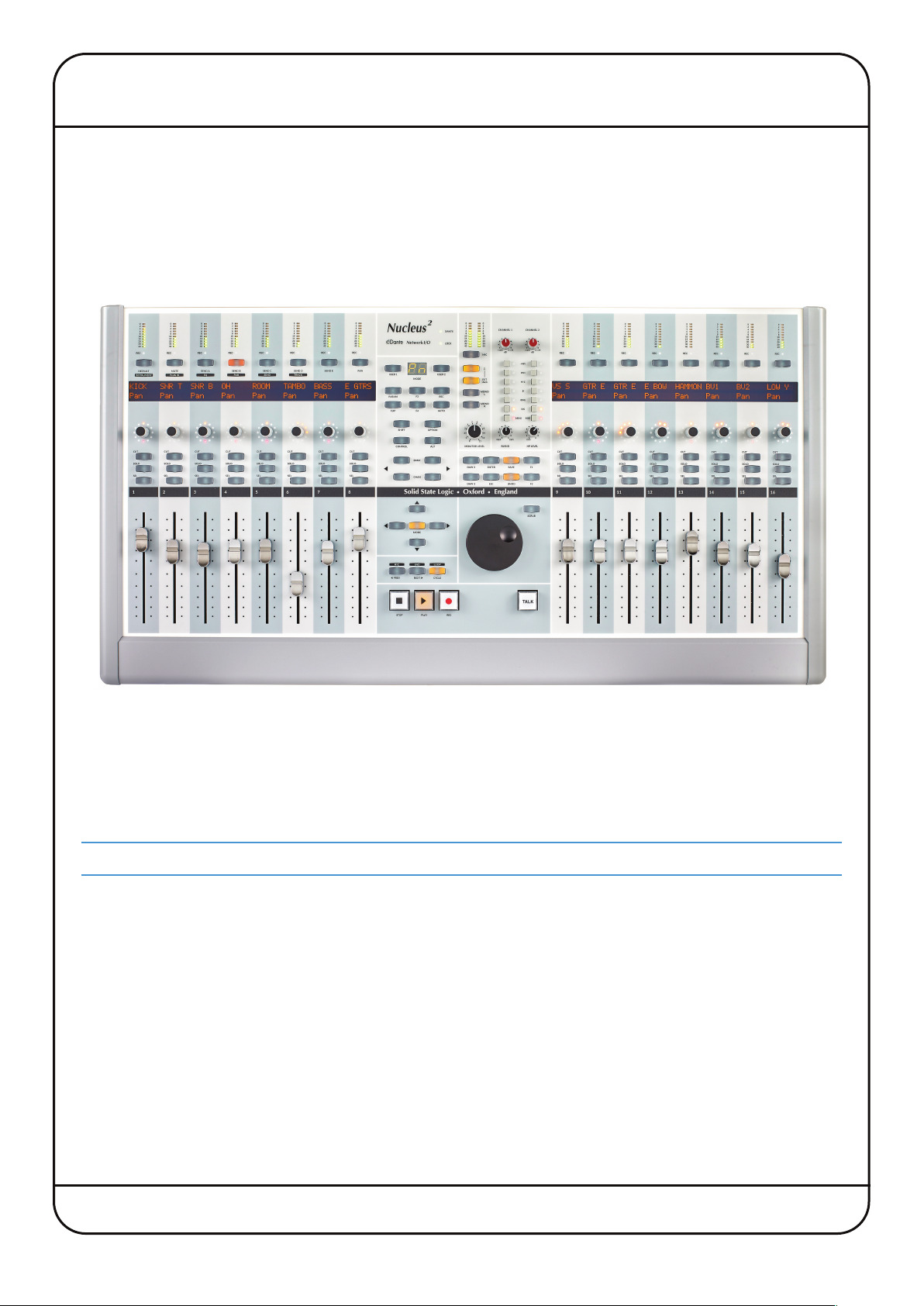
1. Nucleus2 Overview
The diagrams below and overleaf provide an overview of the Nucleus2 control surface along with the main DAW screen of
the Nucleus2 Remote.
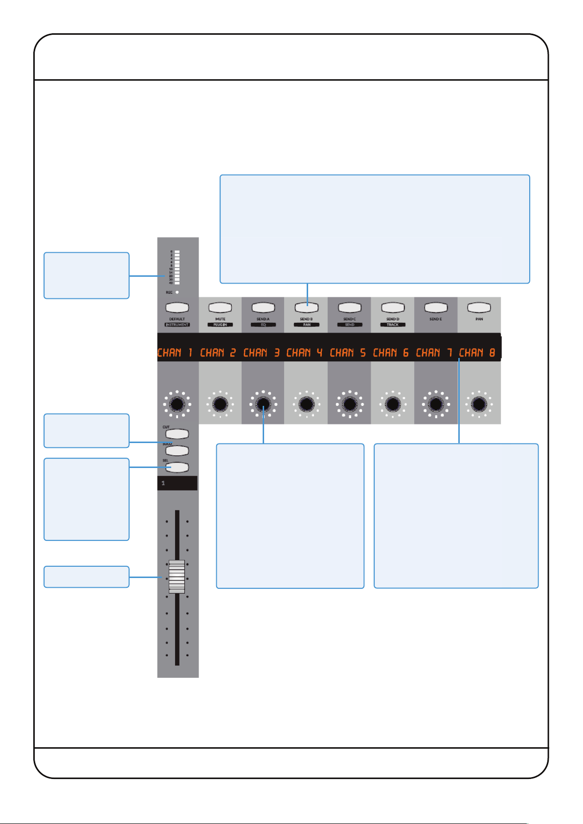
CHANNEL STRIP AND MODE SWITCHES
Mode Switches
The Mode switches are not part of the channel in which they are
located. In normal operation, they select V-Pot modes. By default only
Mode switches 1-8 are assigned. Note that the V-Pot modes are printed
beneath the switches, and not shown in the digital display.
When the USER switches in the centre section are pressed, the Mode
Channel meter
and record status
indicator
and V-Sel switches in channels 9-16 become soft switches (Soft Keys)
which can be configured using the Nucleus2 Remote.
Channel Cut and
Solo switches
Channel Select
switch.
Also used for
track arming,
automation and
plug-in control.
Channel Fader
V-Pots and V-Sel Switches
- Turn for the V-Pot
- Press for the V-Sel switch
Functions are defined by the
host application, or by pressing
a Mode switch.
When the centre section USER
switches are selected, Mode
and V-Sel switches in channels
9-16 become additional soft
switches.
2-Row ‘Scribble Strip’ Display
In normal operation, the top row
displays the channel name and the
bottom row the V-Pot function.
When the centre section USER
switches are selected, the digital
display on channels 9-16 shows the
soft key assignments for each
corresponding Mode and V-Sel
switch.
Nucleus2 User Guide Page 3
Page 8
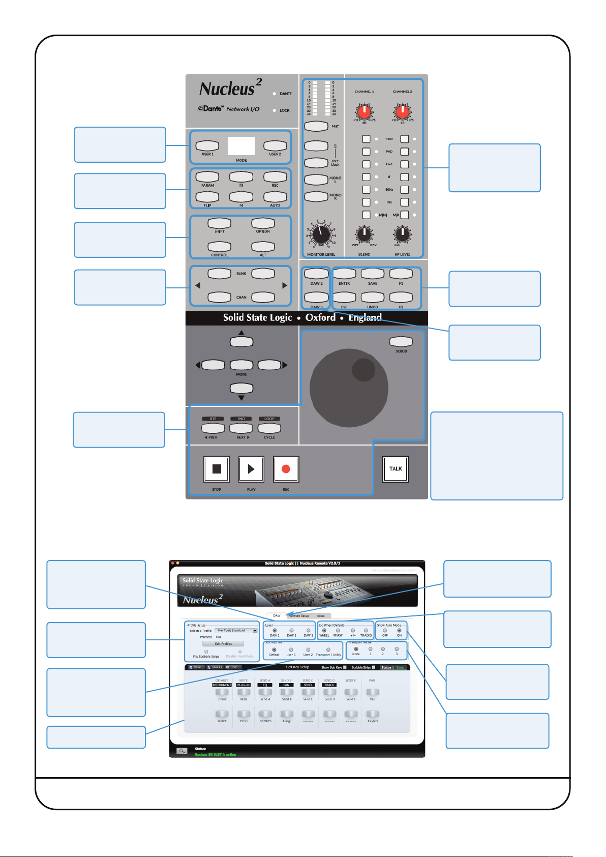
CENTRE SECTION AND ANALOGUE CONTROL
USER Soft Key
Set selectors
DAW Channel
Control modifiers
DAW Computer
modifier keys *
Analogue Control:
Monitoring and
Mic inputs
Channel/Bank
scrollers
* Transport
Control
Nucleus2 REMOTE
Defines which layer
is being edited
in the Remote
* Global DAW
Control keys
Additional DAW
Layer Selectors
Note
The function of switches in
areas with asterisks are
defined in the Nucleus
Remote.
(Default functions are shown.)
Select DAW to view or
edit Nucleus2 setup
2
Defines default
Defines the DAW
being controlled
Selects soft key
sets for the Soft Key
Setup display
Soft Key Setup
Page 4 Nucleus2 User Guide
function of Jog Wheel
Enables single-letter
automation display
Defines which DAW
is transport master
Page 9
2. Nucleus2 Configurations
Connection of Nucleus2 to a Dante network requires the following:
• An Ethernet connection between either of Nucleus
Nucleus2Remote and Dante Standard Audio, if applicable
A USB connection between Nucleus
•
• Audio connections – for recording sources plus monitoring
The way in which audio is sent between Nucleus
associated with the DAW(s) being used. The rest of this section describes the installation and connections involved in
each option.
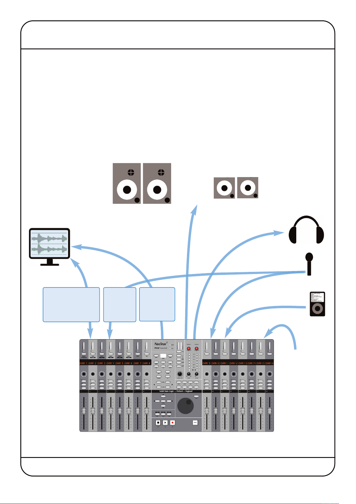
DAWs With a Dante Network Connection
For software which can send and receive audio via any soundcard connected to the computer, Nucleus2 can be connected
directly to the DAW using the Ethernet connection.
2
nd the host DAW computer(s) – for DAW keyboard commands
a
2
’s Ethernet ports and the DAW computer(s) – for DAW control, the
2
and the host DAW computer is dependant on the connectivity options
Monitoring
Headphones
DAW
Computer
Ethernet
(DAW control, Dante
Soundcard and
Remote)
Ethernet
(external
Dante
audio)
Recording
Sources
USB
(DAW
keyboard
commands)
MP3
Player
Mains
Power
Nucleus2 User Guide Page 5
Page 10
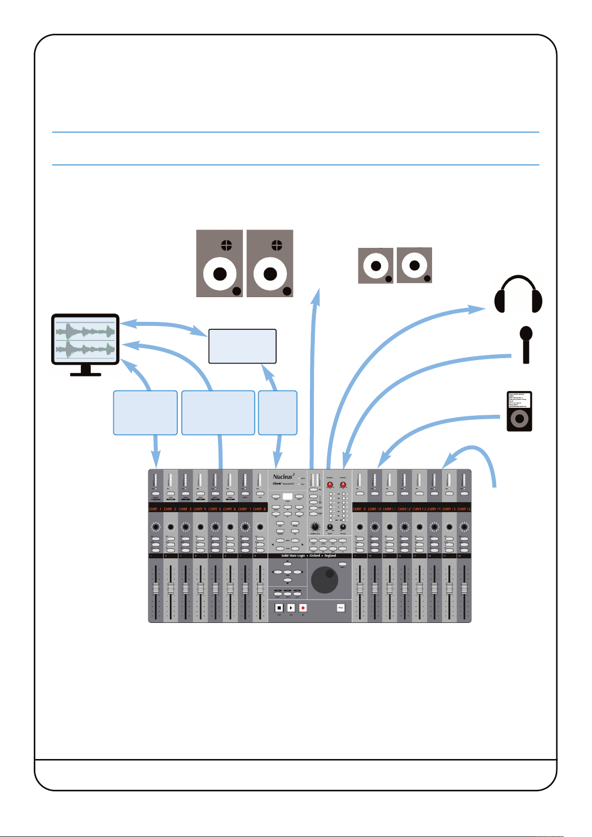
DAWs With Proprietary Soundcards
ome DAWs can only receive audio via their own proprietary soundcard hardware. Many of these soundcards provide
S
igital (S/PDIF) connections, allowing you to take full advantage of the SSL quality pre-amps and converters. The two
d
N
nputs.
i
Using Nucleus
2
ucleus
I
b
nput channels are sent using the left and right channels of the S/PDIF Out, and the S/PDIF In feeds the monitor
i
f your S/PDIF connections are coaxial (usually using phono sockets), simple coaxial to optical S/PDIF converters will
e required to connect the soundcard digitally to the Nucleus
2
’s Digital IO
2
RE
pre-amp) outputs.
P
(
DAW
Computer
Ethernet
(DAW control
and Remote)
Optical to
coax adaptor
USB
(DAW keyboard
commands)
S/PDIF
(digital
audio)
Monitoring
Headphones
Recording
Sources
MP3
Player
Mains
Power
Page 6 Nucleus2 User Guide
Page 11
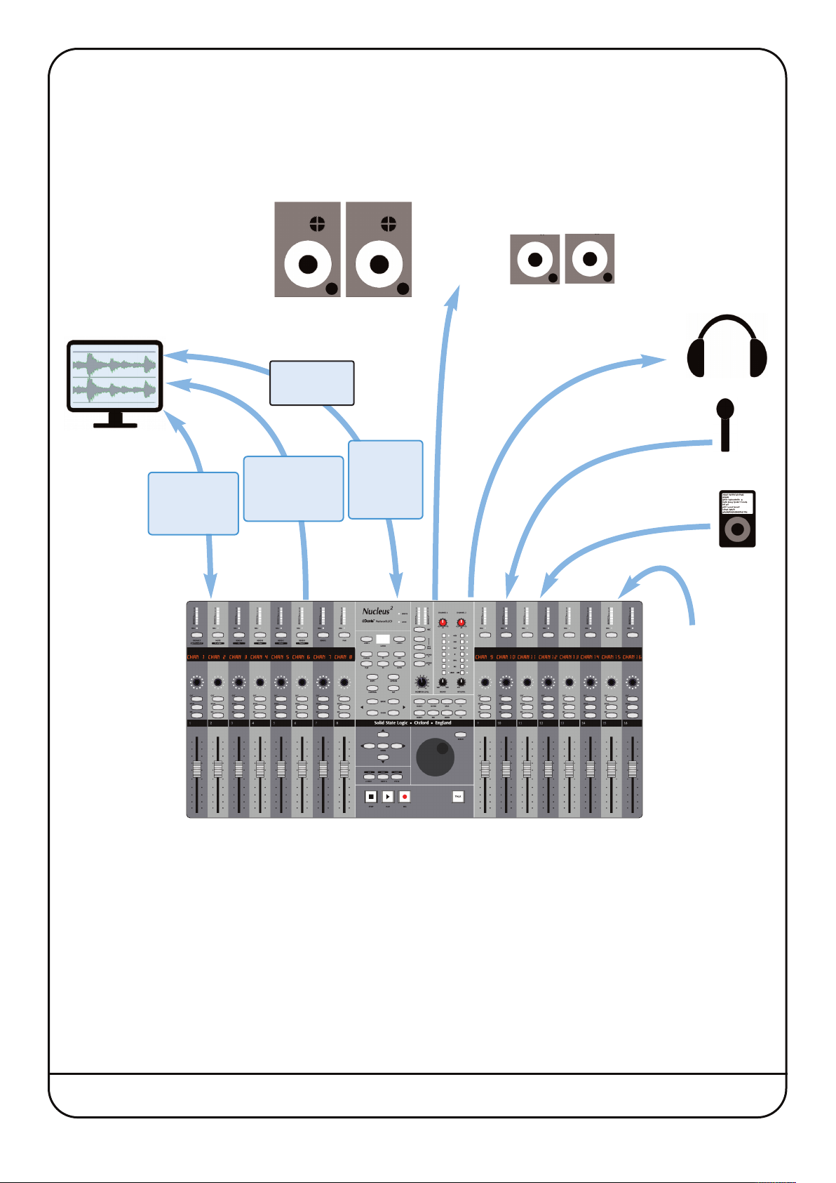
Using Nucleus
or soundcards which don’t have digital IO, line-level analogue connections allow you still to make use of Nucleus
F
re-amps. Nucleus
p
oundcard inputs and outputs. (Note that the PRE amp outputs are sourced from the pre amp’s Insert Send, so are always
s
ctive.)
a
2
’s Analogue IO
2
RE (Pre-Amp) outputs and EXTERNAL monitor inputs can be used to connect Nucleus
P
2
2
s SSL
’
o the
t
Monitoring
Headphones
DAW
Computer
Ethernet
(DAW control
and Remote)
External
Sound Card
USB
(DAW keyboard
commands)
Recording
Sources
SEND Out
and
EXTERNAL
In
MP3
Player
Mains
Power
Nucleus2 User Guide Page 7
Page 12
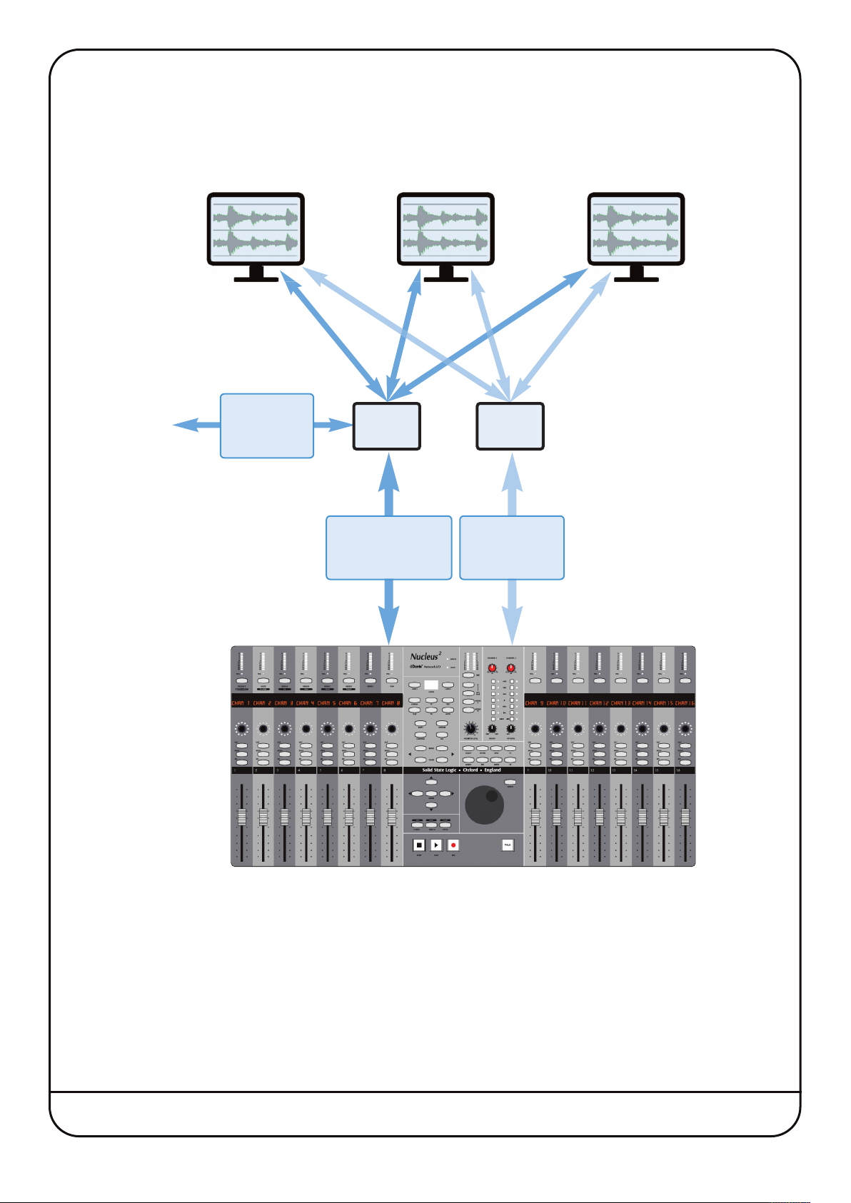
Multiple DAWs
Up to three DAW applications on up to three computers can be connected to Nucleus2 simultaneously, as described on
Page 14. This configuration requires both a Network Router and USB switcher.
Recording
Sources
AW
D
omputer
C
Ethernet
(external
Dante audio)
D
omputer
C
Network
Router
Ethernet
(Dante Soundcard
and Remote)
AW
switcher
(DAW keyboard
commands)
USB
USB
AW
D
omputer
C
Page 8 Nucleus2 User Guide
Page 13
3. Software Installation
In order for Nucleus2 to integrate into your working environment, it will be necessary to install drivers and supporting
software on your DAW computer(s) and/or studio computer(s). The following computers and operating systems are
supported:
Mac
• Intel Core2 Duo, 1.2GHz or faster
• OS X Version 10.8.5 ‘Mountain Lion’ or greater
Windows
• 1.2GHz or faster
• Windows 7, 8, 8.1 and 10 (32 or 64bit)
For all computers, the following resources are required:
• 4GB RAM
• 15MB Hard Disk space
• Internet connection (for product registration and software download)
The
ipMIDI
can either be installed onto one of the DAW computers or onto an entirely different computer if required.
Software Installation – Mac
1. Go to www.solidstatelogic.com, click ‘Register’ in the top right-hand corner, and create an SSL account. If you already
have an SSL account, please login.
2. Click on your Username in the top right-hand corner of the website, then go to ‘My Products’, and click ‘Register a
product’. Select ‘Nucleus’, enter your console serial number, and click ‘Add’.
3. Click on the ‘Downloads’ link that will appear next to your registered Nucleus2console, and download the latest
support file for your OS.
Dante Virtual Soundcard
Installation of the Dante Virtual Soundcard is optional; if you intend to connect Nucleus2to your DAW using only
analogue or S/PDIF audio connections, you do not need to install Dante Virtual Soundcard.
To install the optional Dante Virtual Soundcard application:
• To obtain a Dante Virtual Soundcard license, go to
and create an Audinate account. If you already have an Audinate account, please login.
• Click on your ‘My Account’ in the top right-hand corner and go to ‘My Products’. Beneath ‘Redeem a Software token’,
enter the Dante Virtual Soundcard token included in the Nucleus
and Dante Virtual Soundcard software will be required for one or more DAW computers, Nucleus
www.audinate.com. Click ‘Register’ in the top right hand corner
2
packaging, and submit.
2
Remote
• A DVS license code will now appear in your account – make note of this license code. Go to 'Products' at the top of
the page, and click on 'Dante Virtual Soundcard'. Select your OS version from the drop-down menu and click on the
Download link. Download and run the installer; this will place Dante Virtual Soundcard in the Applications Folder..
• Open the Applications folder, and double-click the Dante Virtual Soundcard icon. Click on Licensing, and enter the
license that was generated in your Audinate account. To find this again, go to
My Products.
• To uninstall Dante Virtual Soundcard simply drag the application to the Trash.
Nucleus2 User Guide Page 9
www.audinate.com, login, and go to
Page 14
Dante Controller
nstallation of the Dante Controller is optional; if you intend to connect Nucleus
I
/PDIF audio connections, you do not need to install Dante Controller.
S
• To install Dante Controller, go to
udinate account. If you already have an Audinate account, please login.
A
ww.audinate.com. Click ‘Register’ in the top right hand corner and create an
w
2
o your DAW using only analogue or
t
• Go to ‘Products’ > ‘Dante Controller’ and choose a download appropriate for your version of OS X.
• Locate the downloaded package in the Finder window and double-click to launch the installer. The installer will place
the Dante Controller app into your Applications folder.
– If it becomes necessary to uninstall Dante Controller, simply drag the application folder to the Trash.
2
Nucleus
• To install Nucleus
Remote
2
Remote, simply drag the Nucleus2 Remote icon to the Applications folder alias. This will copy the
application onto the computer.
• To run Nucleus
2
Remote, locate and double-click the Nucleus
2
Remote icon in the Applications folder. If required,
drag this icon to the Dock on the Desktop to provide quick and easy access.
– If it is necessary to uninstall Nucleus2 Remote, simply locate the Nucleus2 Remote icon in the Applications folder and
drag it to the Trash.
ipMIDI Driver
If an older version of the
installer; simply delete the
ipMIDI
driver is already present on the computer, it must be removed prior to running the
ipMIDIDriver.bundle
file from the
/Library/Audio/MIDI Drivers
folder.
• To install the ipMIDI driver, locate the ipMIDI package in the Finder window. Double-click this icon to launch the ipMIDI
installer. Follow the instructions in the installer (it should be safe to accept the defaults).
It will be necessary to log out and back in again after the driver has been installed.
– To uninstall the ipMIDI driver, simply delete the
ipMIDIDriver.plugin
file from the
/Library/Audio/MIDI Drivers
folder.
Page 10 Nucleus2 User Guide
Page 15
Software Installation – Windows
1. Go to
www.solidstatelogic.com click ‘Register’ in the top right-hand corner, and create an SSL account. If you already
have an SSL account, please login.
2. Click on your Username in the top right-hand corner of the website, then go to ‘My Products’, and click ‘Register a
product’. Select ‘Nucleus’, enter your console serial number, and click ‘Add’.
3. Click on the ‘Downloads’ link that will appear next to your registered Nucleus2console, and download the latest
support file for your OS.
Dante Virtual Soundcard
Installation of the Dante Virtual Soundcard is optional; if you intend to connect Nucleus2to your DAW using only
analogue or S/PDIF audio connections, you do not need to install Dante Virtual Soundcard.
To install the Dante Virtual Soundcard application:
• To get a Dante Virtual Soundcard license, go to
www.audinate.com. Click ‘Register’ in the top right hand corner, and
create an Audinate account. If you already have an Audinate account, please login.
• Click on your ‘My Account’ in the top right-hand corner, and go to ‘My Products’. Beneath ‘Redeem a Software token’
enter the Dante Virtual Soundcard token included in the Nucleus2packaging, and submit.
• A DVS license code will now appear in your account – make note of this license code. Go to 'Products' at the top of
the page, and click on 'Dante Virtual Soundcard'. Select your OS version from the drop-down menu, and click on the
Download link. Download and run the installer; this will place a Dante Virtual Soundcard shortcut on the Desktop.
• Open Dante Virtual Soundcard from the Desktop icon. Click on Licensing, and enter the license that was generated in
your Audinate account. To find this again, go to www.audinate.com, login, and go to My Products.
– To uninstall Dante Virtual Soundcard run the Uninstall application located in the Dante Virtual Soundcard folder.
Dante Controller
Installation of the Dante Controller is optional; if you intend to connect Nucleus2to your DAW using only analogue or
S/PDIF audio connections, you do not need to install Dante Controller.
• To install Dante Controller, go to www.audinate.com. Click ‘Register’ in the top right hand corner and create an
Audinate account. If you already have an Audinate account, please login.
• Go to ‘Products’ > ‘Dante Controller’ and choose the appropriate download for your Windows version.
• locate the Dante Controller Setup application and double-click this file to run the installer. Follow the instructions in
the installer application. The installer will place a shortcut on the Desktop; double-click this shortcut to run Dante
Controller.
– If it becomes necessary to uninstall Dante Controller, run the Uninstall application located in the Dante Controller
folder.
Nucleus
• To install Nucleus
2
Remote
2
Remote, locate the Nucleus2 Setup application and double-click this file to run the Nucleus
Remote installer. Follow the instructions in the installer (it should be safe to accept the defaults).
• On completion of the installation process, the installer will place a shortcut on the Desktop; double-click this icon to
2
run Nucleus
– The Nucleus
Remote.
2
Remote can be un-installed by running the Uninstall application located in the Nucleus2 Remote folder.
Nucleus2User Guide Page 11
2
Page 16

ipMIDI Driver
f an older version of the
I
rograms
P
• To install the ipMIDI driver, locate the ipMIDI Setup application and double-click this file to launch the ipMIDI installer.
ollow the instructions in the installer (it should be safe to accept the defaults).
F
t will be necessary to restart the computer after the driver has been installed.
I
• To remove the ipMIDI driver, simply run the Uninstall application located in the ipMIDI folder.
before running the installer.
)
pMIDI
i
river is already present on the computer, it should be uninstalled (using
d
dd/Remove
A
Page 12 Nucleus2User Guide
Page 17
4. Connection and Software Configuration
PHYSICAL CONNECTIONS
he Installation Guide that came with Nucleus
T
uide before attempting to connect Nucleus
g
The mains power connection for Nucleus2 is via a standard 3-pin IEC320 power cable into its external power supply. The
following audio and data connections can be found on the Nucleus
Audio Connections
PRE IN, PRE IN Combi inputs for Nucleus2 pre-amps 1 and 2, XLR connections are routed via the pre-amps;
plugging in a 1/4" jack will automatically select the high input impedance on the channel strip.
SEND/RETURN and Balanced 1/4" jack Insert Send and Return connections for pre-amps 1 and 2. (The Sends also
function as balanced Mic-pre outputs)
Inserts can also be used on the monitor circuits – see Page 42 for details.
EXTERNAL L and R Balanced XLR input for connecting an additional stereo signal to the Nucleus2 monitoring
MONITOR L and R Balanced XLR outputs for connecting the Nucleus2 monitoring to a pair of loudspeakers
MINI L and R Balanced XLR outputs for connecting Nucleus2 to an auxiliary pair of loudspeakers
HEADPHONES 1/4" stereo headphone connections. Both sockets send identical signals
TALKBACK IN Balanced XLR input for talkback; with adjustable gain
IJACK 3.5mm stereo jack input provides an additional source into the monitoring and headphone sends
2
ontains important safety information. Please be sure to read that
c
2
.
2
back panel:
SPDIF Optical S/PDIF stereo IO. The outputs of the Nucleus2 pre-amps feed the S/PDIF output (channel
1 is left, channel 2 is right) and the S/PDIF inputs feed the External monitor connection
Data Connections
Both Network and USB connections must be made between Nucleus2 and the DAW computer(s) – for systems using
multiple computers, see Page 16.
NETWORK Standard RJ45 Ethernet connector for DAW data and Dante audio. The two ports function as a
network switch so either can be used for Dante and DAW control. The unused port may be used
for additional Dante Network devices.
USB Use a standard USB A-B cable to connect Nucleus2 to a USB port on your DAW computer. This
connection is used for keyboard commands to the DAW.
Defining Keyboard Nationality (Mac)
Nucleus
you to identify the new keyboard. In order to identify the keyboard type, the Mac then requires the key to right of the left
Shift key to be pressed. Mode switch 16 on Nucleus2 (see Page 27), is assigned a ‘Keyboard ID’ command by default;
pressing this switch – labelled ‘KEYBID’ – will send the required keystroke to the Mac to correctly identify Nucleus2 as a
UK keyboard.
FOOTSWITCH Two footswitches can be connected to Nucleus
TERMINAL The TERMINAL D-connector is used for advanced system configuration and diagnostics. We
2
emulates a UK keyboard. When Nucleus2 is first connected to a Mac, a dialogue will be displayed which asks
2
using the single 1/4" stereo (X-Y) jack
FOOTSWITCH connector – use a mono-to-stereo splitter cable to separate the two footswitch
connections.
strongly suggest not using this unless you are confident with terminal procedures and have an
in-depth understanding of quantum theory.
Nucleus2 User Guide Page 13
Page 18

CONFIGURING NETWORK CONNECTIONS
Network Wiring
To ensure the fastest possible communication between your DAW computer and Nucleus2 – and to simplify the installation
wiring – Nucleus2 communicates with your workstation over Ethernet using the ipMIDI driver to emulate a multiport MIDI
interface. To ensure minimum latency ipMIDI uses multicast UDP rather than TCP/IP. This means that:
• The network connection should be short and direct.
Where possible all cables should be as short as possible and only routers that can support high data transfer rates
should be used. Problems have been experienced with some domestic routers, particularly when used with Pro Tools.
Typical symptoms of a slow network connection are:
- The Nucleus
- Channel controls and scribble strips on channels 9-16 fail to update reliably when using the CHANNEL scroller
switches.
• All computers on the network will receive ipMIDI packets.
Notes for network wizards
Because ipMIDI uses multicast UDP packets, messages between one computer and Nucleus2will be received by all
other computers on the network, potentially causing problems in installations with more than one Nucleus2. The UDP
packets can be blocked by using a firewall router and connecting the main network to the WAN connector. The firewall
can then be configured to allow all traffic apart from UDP ports 21928 through 21947 which are used by ipMIDI and
port 50081 which is used by the Nucleus2Remote application. Note that it may be necessary to use a separate Ethernet
switch in place of the integrated firewall router switch, as some of these can not support the high data transfer rate
required. The NetGear GS108 (an eight port switch) has been used successfully at SSL Begbroke. A pre-
configured LAN Integration Network Switch can be purchased from the SSL web store. Also see
setup example on page 16
2
fails to synchronise all controls when first connecting with the DAW.
To avoid the latency and communication issues illustrated above, we recommend that Nucleus2 and the DAW computers
be connected directly on a dedicated network. In practice, most systems can be configured with a direct connection.
Assigning the Nucleus2 IP Address
The Nucleus2 IP address is configured via the Network Setup tab
in the Nucleus2 Remote.
By default, Nucleus2 uses a fixed IP address of 169.254.1.2 – the
IP Address, Subnet and Gateway shown in the picture should work
for a direct connection to a single DAW computer.
We suggest you do not attempt to change these unless you are
familiar with Ethernet configuration as doing so may break
communication between Nucleus2and the Remote.
If Nucleus2 must be connected via a wider network – ideally, in
that case, through a network switch or router – Nucleus2 should
probably be set to use a DHCP server (check the Use DHCP option)
to automatically set an IP Address, Subnet and Gateway suitable
for your wider network. If there is any possibility that a DHCP server
is not available the Fixed option should be used.
Page 14 Nucleus2 User Guide
Page 19

Direct Network Connection Configuration (Mac)
Connect your Nucleus
to Fixed in the Nucleus
2
directly to the DAW computer using a standard network cable, and check that the IP address is set
2
Remote (see previous page).
OS X does not currently allow two ports to be used for IP traffic – your main network connection will become
unavailable when using Nucleus2.
• On the Mac, open the Network control panel in System
Preferences, and use the LOCATION: drop-down to
create a new location. Next select the Mac Ethernet port
to which you have connected Nucleus2 and configure it
as shown below.
On OSX version 10.11 ‘El Capitan’, a router address will
be required for two-way data communications – please
ensure this is entered as shown in the Network
Preferences panel.
• Launch the Nucleus
2
Remote application and check it
connects to your Nucleus2, as described on Page 21.
Wider Network Connection Configuration (Mac)
2
For connecting Nucleus
to a managed switched / wider
network (a multi-studio facility for example), you will need
to set the Mac Network setting ‘Configure IPV4’ to Using DHCP. The same must be done in the Nucleus Remote ‘Network’
Tab.
Both the Nucleus2and your computer will then be assigned IP addresses automatically.
If using more than one ipMIDI controller/console, a pre-configured switch is available from the SSL web store which
will prevent the two consoles from communicating across the network.
Direct Network Connection Configuration (Windows)
• Connect your Nucleus2directly to the DAW computer using a standard
network cable, and then check that the IP address is set to Fixed in the
Nucleus2Remote (see Page 14)
• On the PC, open the control panel, click on ‘view network status and
tasks’, the ‘local area connection’ for your Nucleus2, ‘Properties’, then
double-click ‘Internet Protocol Version 4 (TCP/IPV4). Make sure that the
port is set to ‘Use the following IP address’, and set the IP as shown
below.
2
• Launch the Nucleus
Remote application and check it connects to your
Nucleus2as described on Page 21.
Wider Network Connection Configuration (Windows)
2
For connecting Nucleus
to a managed switched / wider network (a multi-
studio facility for example), you will need to configure your computer to
Obtain an IP address automatically in the Properties window.
Both the Nucleus
2
and your computer will then be assigned IP addresses
automatically.
Nucleus2 User Guide Page 15
Page 20

Connecting Nucleus
2
to Multiple Computers
Connecting a Nucleus2 to multiple DAW computers introduces a little more complexity.
Network
o connect Nucleus
T
ia a network switch or router with sufficient bandwidth to cope with the volume of data which is transferred to and from
v
N
ucleus
2
It is essential that you take note of the configuration issues described previously.
.
2
o multiple DAW computers, you will probably need to connect the Nucleus
t
2
nd all the computers
a
Note that when connected to a wider network, via a router or switch, a DHCP server will probably be available and so
Nucleus2 would normally be set to use it rather than the default fixed IP address. See Page 14 for details.
USB
A USB switch will be necessary for switching the USB connection between computers. This can best be provided by using
KVM (‘Keyboard, Video, Mouse’) switch with switchable USB ports. If an ‘automatic’ unit is obtained, Nucleus2 can be
configured to issue the appropriate command ‘KVM hot key’ to the KVM to select the correct USB port whenever a different
DAW Layer is selected on Nucleus2. By plugging your keyboard (& mouse) into the Nucleus2 USB hub, both Nucleus2 and
your keyboard (& mouse) can be switched together.
IP Network
Network
USB
Network
USB
USB switch
Firewall (option)
Switch/Router
USB hub
USB Network
Page 16 Nucleus2 User Guide
Page 21

IPMIDI CONFIGURATION
he ipMIDI driver enables your DAW to send and receive MIDI control data via the network connection, and must be
T
onfigured to match the requirements of Nucleus
c
Mac
Once the driver has been installed and you have logged back in, use the Finder to navigate to the Utilities folder (in
Applications). Double-click Audio MIDI Setup, select MIDI Devices and double-click on the ipMIDI icon. Set the number
of MIDI ports to 6 in the resulting pop-up.
Windows
Once the computer has restarted after installing the driver, right-click on the ipMIDI icon in the Task Bar, select ipMidi -
MIDI over Ethernet and set the number of MIDI ports to 6 in the resulting pop-up.
MIDI Port Mapping
2
MIDI control for the three Nucleus
Layers is split across the six ipMIDI ports which means that your DAW must be
configured to match the following:
Nucleus2 DAW Layer Nucleus2 Channels ipMIDI port
2
efore it can be used.
b
1
1 to 8 1
9 to 16 2
1 to 8 3
2
9 to 16 4
1 to 8 5
3
9 to 16 6
Note that CC Layers only use the first MIDI port in their layer. All CC data is sent on MIDI Channel 1.
Setting which ipMIDI ports the DAW should use is performed using the MIDI controller configuration page of your DAW.
Below and overleaf are two examples using Pro Tools 8 and Logic Pro 9.
Pro Tools
In the Setup menu, click on Peripherals and select the MIDI Controllers tab.
For MIDI controllers 1 and 2, select ‘HUI’ as the MIDI controller ‘Type’ and assign the MIDI ports for this layer’s DAW to the
two MIDI controllers, as listed in the table above.
As an example, if Pro Tools has been assigned to Layer 1 (so using ipMIDI ports 1 & 2), the MIDI Controllers tab should
look as opposite.
Nucleus2 User Guide Page 17
Page 22

Logic Pro
Control surfaces are setup via the Logic Pro X > Control Surfaces > Setup menu (or Preferences > Control Surface Setup if
using Logic 9 or below). In this example we will setup Logic for operation on DAW layer 1 of Nucleus
1. Choose New and then Install…
2
.
2. Choose Nucleus (left) and then Add
3. Set both Output Port and Input Port to Port 1
4. Again, Choose New and then Install…
5. Choose ‘Nucleus (right)’ and then Add
6. Set both Output Port and Input Port to Port 2
The actual ipMIDI ports used will depend on which
layer (or layers) have a Logic Profile assigned.
(Refer to the previous page for a list of Nucleus
2
’s
MIDI port assignments.)
It is recommended that you delete any controllers
automatically created on set-up, and recreate them
manually. Note that if the physical arrangement is
reversed, then the Nucleus2faders will not map correctly
to the on-screen faders in Logic.
If Logic is the only DAW connected to Nucleus2,
then provided that there is only one DAW Layer set
up with an MCU based Profile, Logic should
automatically detect the two virtual controllers which will be shown in the Logic Control Surface Setup menu (as shown
above), with the appropriate Nucleus2 ipMIDI ports assigned. If Logic fails to detect the control surfaces, then the
controllers can be added manually via New > Install menu and the appropriate MIDI Out port and Input assigned. Full
details can be found in the online Logic Pro Control Surfaces Support Guide in the Logic Help menu.
If Nucleus2 is set up with multiple MCU profiles in the DAW layers, then the automatic detection option must be disabled
and the controllers added and configured manually. Check the Disable Handshake box in the DAW tab in Nucleus2 Remote
(located below the Edit Profiles button) for all the DAW layers assigned to a MCU Profile prior to starting the Logic
application. This will prevent Logic automatically detecting multiple Nucleus2Controller layers.
For other DAWs, please refer to the relevant User Guide for details about configuring MIDI controllers.
See Section 5 for a description of the Remote’s
DAW
tab.
Page 18 Nucleus2 User Guide
Page 23

DANTE SOUNDCARD CONFIGURATION
Setup Go to www.audinate.com, click Register in the top right hand corner, and create an account. Under My Account go to My
Products, and enter the Dante Virtual Soundcard token code – included with Nucleus2– in this box.
Click submit, and this will provide you your license listed in the account. Take note of this license code.
Below the license code you will see a link appear. This will take you to the latest installer for Dante Virtual Soundcard.
Download and run the installer.
Once installed, open Dante Virtual Soundcard, enter the license code and click Activate.
• Set the Audio Channels to 2 x 2*, latency to 4ms, and
Network interface to en0. Click Start, and your computer
will now be available as a device on your Dante network.
*Or 4x4 if using the SPDIF alongside the analogue connections.
It is important to configure your computer IP address before proceeding. See pages 15 and 16 for details.
Now you need to connect the audio routes from the Nucleus2to the computer. This is achieved using the Dante Controller
software.
• Open Dante Controller (after installation), expand the routing
matrix by clicking the ‘+’ button
• Click the two audio cross-points between the Nucleus2and
your computer for the inputs, and then the two audio crosspoints for your outputs. You make a connection by clicking on the
cross-point
• For a standalone system with the mic pre’s routed into the
DAW, and the DAW ‘Mix’ output routed to the monitor
outputs, you should connect channels 1&2 (on the
Nucleus2) to channels 1&2 (on the computer) for both the
inputs and outputs. See image to the right
• Inputs and outputs 3&4 of Nucleus
Right input and SPDIF Left and Right output respectively.
2
are the SPDIF Left and
The SPDIF I/O on channels 3&4 is only available on the Dante Network at low sample rates (44.1/48kHz). At higher
sample rates (88.2/96kHz) only the analogue I/O on channels 1&2 will be available.
Nucleus2 User Guide Page 19
Page 24

Sample rate
To change the sample rate on both your
Nucleus2and the Virtual Soundcard:
• On the computer, double-click on the device
you wish to change in Dante controller
• Select the Device Config tab. The sample
rate for each device can be selected via the
drop down list (see image).
The LOCK LED in the centre of the console will
be illuminated when locked and off if there is
an error with the Dante clock.
Stand-alone System vs Wider Dante Network
The description here is for configuring the Nucleus2soundcard in a stand-alone system (with the DAW control and
Nucleus2audio being the only networked device connected to one computer at any time). For more details on configuring
an expanded Dante audio network with other Dante based products, please see the Audinate website here.
We also recommend viewing the useful videos about Dante Virtual Soundcard and Dante Controller here
SPDIF I/O & EXTERNAL SOUNDCARD
Setup
If you do not need to use the Dante soundcard
in Nucleus2and instead want to configure the
SPDIF inputs and outputs with an existing
soundcard in your setup, you need to first go to
the Nucleus2Remote application, go to the
Network Setup tab and un-tick the Dante
Enabled option (see image). The ‘Dante’ LED in
the centre of the console will switch off.
Clocking
The SPDIF inputs have sample-rate conversion,
and the outputs clock to the internal soundcard.
This means that when both SPDIF inputs and outputs are connected, the Nucleus
SPDIF device you connect should clock to the SPDIF outputs. When only using the SPDIF inputs for monitoring, the external
device can be clock-master as these have SRC’s on the input.
2
must be the clock-master. The external
The SPDIF I/O will only operate at lower sample rates (44.1/48kHz)
Page 20 Nucleus2 User Guide
Page 25
5. Nucleus2 Remote
The Nucleus2 Remote performs an essential role in defining how Nucleus2 functions, from the control protocol being used
to the functions assigned to many of the Nucleus2 switches. The Remote can be run from any computer that has access
to Nucleus2 over Ethernet.
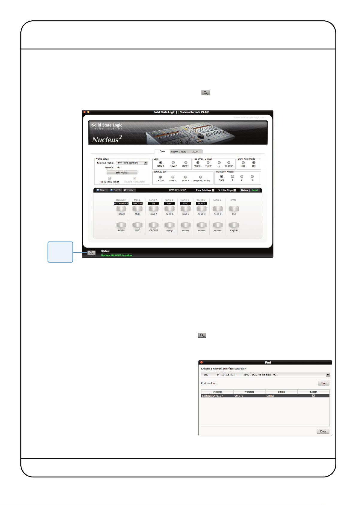
ESTABLISHING THE REMOTE CONNECTION
In the bottom left-hand corner of the Remote window there is a Find ( ) button, along with an indication regarding the
current status of the connection to Nucleus2.
Find
button
When the Nucleus2 Remote first opens, it searches for a Nucleus2 console to control. If it finds one, it will automatically
link to that console and a Nucleus2 SN nnnn is online message will appear (in green) in the Status field, where ‘SN nnnn’
is the ID of the selected Nucleus2 console .
If this is the first time that you have run the Nucleus2 Remote, and it is unable to locate a Nucleus2 unit, the current status
will be shown (in red) as No Nucleus2 Selected – Click on Find. Alternatively, if the Remote has previously been used but
it cannot find the Nucleus2 console it expected to locate, the current status will instead display the message Nucleus2 SN
nnnn is offline where ‘SN nnnn’ is the ID of the Nucleus2 console expected.
If this happens, first check your connections and then click on the button to bring up the Find pop-up. Clicking the
Find button in the top right of the pop-up will cause the Remote to then scan for consoles. The Choose A Network Interface
Controller dropdown menu is used to focus the search when connected to different networks. In a standalone, single
console setup, select the Default option.
Once the Remote has found the console, it will appear in the popup. Check the Select box for the correct console and click on the
Close button.
Once a connection has been made to a Nucleus
nnnn is online message will appear in the Status field, where ‘SN
nnnn’ is the ID of the Nucleus2 console selected.
2
, a Nucleus SN
Nucleus2 User Guide Page 21
Page 26

REMOTE TABS
he row of tabs across the top of the window define what is displayed in the rest of the window.
T
he DAW Tab
T
2
The DAW tab is where most of the action occurs and is used for configuring the selected Nucleus
as described in this Section of the manual.
he Network Setup Tab
T
The Network tab is used for configuring the Nucleus
The About Tab
The About tab displays current software and firmware versions, and provides links to support areas of the Solid State
Logic website.
2
network connection, as described in Section 4.
and its control protocol
Page 22 Nucleus2 User Guide
Page 27
REMOTE LAYER SELECTION
efore adjusting any of the settings in the Remote, the Layer to which the settings refer must
B
e defined. This is done by clicking on the DAW 1, DAW 2 and DAW 3 buttons in the Layer area
b
owards the top of the DAW tab in the Remote window.
t
The only area of the
DAW
tab which is not Layer-specific is the
Transport Master
area – see Page 26 for details.
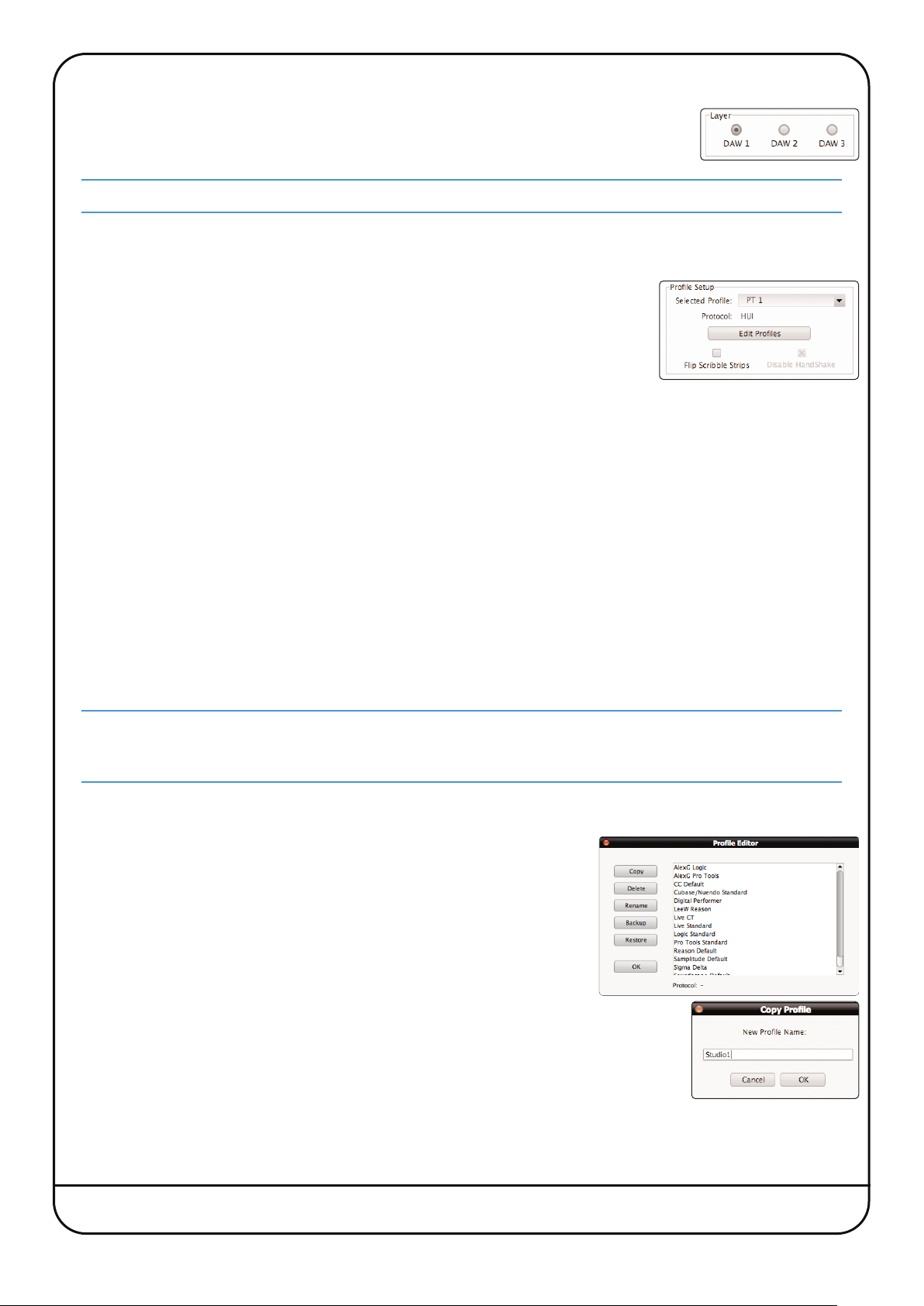
LAYER PROFILE CONFIGURATION
Protocols DAW control protocols are selected as part of the Layer’s Profile, configured in the Profile
Setup area in the top left corner of the Remote’s DAW tab.
There are eight default Profiles supplied with Nucleus
A HUI Profile configured for Pro Tools An MCU Profile for Nuendo/Cubase
An MCU Profile configured for Logic An MCU Profile for Reason
An MCU Profile configured for Ableton Live An MCU Profile for Samplitude
A Continuous Controller (CC) Profile for use with MIDI devices An MCU Profile for Studio One
These Profiles provide starting points for the creation of more personalised Profiles. They include only basic soft key
assignments, allowing plenty of space for the user to configure their own Profiles.
Profiles for other DAW packages can also be created from the default Profiles, using the Pro Tools default Profile for DAWs
that support the HUI interface, and the Logic default Profile for DAWs that conform to the MCU protocol.
Note that the default Profiles themselves cannot be edited. Profiles are personalised by creating copies of a default Profile
which can then be edited, as described on the following pages.
2
:
The soft key sets included in the default Profiles are described on Pages 27 and 28 and the full list of functions available
within each protocol can be found in the Appendix.
All the Profiles available to Nucleus2 are stored on the SD card in the card slot on the rear panel of the unit. If the
card is not present no Profiles will be available – when a blank card is inserted, the eight default Profiles will be
created and stored on the card when firmware is re-installed.
Creating Profiles – Method 1
1. To create a new Profile, press Edit Profiles to bring up the Profile Editor
pop-up. Select the Profile which you wish to use as a starting point and
click the Copy button.
2. Type a name for the new Profile into the Copy Profile pop-up which appears,
and click on OK.
3. After a moment, the new Profile will appear in the Profile list in the Profile
Editor. The selected Profile’s protocol is indicated at the bottom of the popup, as well as in the Profile Setup area.
4. Click OK to exit the Profile Editor.
Nucleus2 User Guide Page 23
Page 28

Creating Profiles – Method 2
An alternative way to create new Profiles is to use the Save As button in the Soft Key Setup area which makes up the
bottom half of the DAW tab.
1. First select the Profile you want to use as a starting point and assign it to a layer, as described on the previous pages.
2. Click the Save As button in the Soft Key Setup area at the bottom of the window to bring up the Save Profile As pop-
up.
3. Type a name for the new Profile into the pop-up and click on OK.
After a moment, the new Profile will be created and become active in that layer.
Selecting a Profile
Profiles are selected and managed using the Profile Setup area in the top left corner of the DAW tab. The four default
Profiles are listed in the drop-down Selected Profile menu, along with any derivatives of them which you have created.
If the Profile you select uses a different protocol than that currently assigned to the layer selected in the Remote, or if the
layer previously contained no Profile, a pop-up will appear asking you to restart Nucleus2 – with a ‘Now’ or ‘Later’ option.
Press OK to close the pop-up. A number of functions within the DAW tab will now be locked out until the restart. However,
further Profile selections can be made before restarting. To perform a restart simply re-power Nucleus2 using the power
switch on the rear of the unit.
Note that, depending on the complexity of your setup, you may also need to re-find Nucleus2 in the Remote after the
restart, as described on Page 21.
MCU User Display Configuration
In order to cater for variations in the ways in which MCU protocol DAWs return channel data to the scribble strip displays,
there is a Flip Scribble Strips box in the Profile Setup area. Actioning this function switches the two rows of the Nucleus
scribble strip display, allowing Nuendo labelling to emulate the Logic format for example. By default, Flip Scribble Strips
is therefore enabled for the default Nuendo Profile and disabled for the default Logic Profile. For other MCU protocol DAWs,
the labelling format described in the DAW’s Control Surface documentation will enable you to ascertain whether or not to
activate this function.
MCU User Handshake Disabling
The Disable Handshake box located below the Edit Profiles button is also only required for MCU protocol DAWs. This
function will only be of use in systems where there are multiple MCU layers in use, and where these layers include both
Logic and other MCU protocol DAWs. Checking this box will stop MCU programs from handshaking with each other via
Nucleus
2
, thus preventing Logic from scanning for external controllers and subsequently creating ghost controllers of any
other MCU programs.
2
Nucleus2 must be power cycled before a
Disable Handshake
status change will take effect.
Page 24 Nucleus2 User Guide
Page 29

Managing Profiles
The Profiles are all stored on the SD card plugged into the rear of Nucleus
2
, not the computer the Remote is running on.
Profiles are however easily copied, renamed, deleted and backed up using the browser as well as being physically
transferable from one unit to another if required.
Deleting Profiles
o delete a Profile, click on Edit Profile to bring up the Profile Editor pop-
T
p, select the Profile which you wish to delete, and click Delete.
u
lick OK in the warning pop-up which appears, and after a moment the
C
rofile will disappear from the list in the pop-up. Click OK to exit the
P
rofile Editor.
P
Renaming Profiles
To rename a Profile, press Edit Profile to bring up the Profile Editor pop-up and select the
Profile which you wish to rename.
Click on Rename to bring up the Rename Profile pop-up. Type a new name for the Profile into
the pop-up and click OK. The Profile’s name will change in the Profile list in the Profile Editor.
Backing up Profiles
To back up a Profile or export it for use elsewhere, click on Edit Profile to bring up the Profile Editor popup, select the
Profile which you wish to back up, and click Backup. In the pop-up which appears, edit the name and destination of the
.zip
file if necessary, and click on Save. Your Profile will be exported as a compressed
file.
Restoring Profiles
To restore a Profile from back-up or import a Profile created using another Nucleus2 Remote, click on Edit Profile to bring
up the Profile Editor popup and click Restore. In the pop-up which appears, locate the Profile file (a compressed
.zip
file) that you wish to restore and click on Open. The restored Profile will appear in the Profile list.
If the Profile name already exists the restored filename will be appended with number to distinguish it from the
existing Profile of the same name. You can rename the Profile as described above.
Nucleus2 User Guide Page 25
Page 30

TIMELINE FUNCTIONS
Transport Master
Nucleus2 directs transport commands to whichever DAW is currently selected on
Nucleus2 but if multiple DAWs are being used simultaneously it is possible for one DAW
to be made the Transport Master. When a DAW has been set as the Transport Master,
Nucleus2 will then always direct transport commands to that DAW, regardless of the
DAW (Layer) selected on the control surface. DAW transports on other Layers will be
slaved to the master DAW.
To assign a DAW Layer to be the Transport Master, click on the 1, 2 or 3 button in the Transport Master area of the Remote’s
DAW tab. To have no Transport Master, select the None button.
Note that the
Layer
area.
Note also that a DAW Transport Master is not required when controlling multiple DAWs that are connected as ‘ReWire’
slaves to the Master DAW. See the relevant DAW User Guide(s) for more information.
Jog Wheel Function
The function of the centre section jog wheel is selected in the Jog Wheel Default area of
the Remote’s DAW tab.
The four options are as follows:
Wheel Sends basic control information which scrolls the timeline in most DAWs
Pro Tools Users. Note that the wheel does nothing in ‘Wheel’ mode until ‘Jog/Shuttle’ mode is activated – by default
‘Jog/Shuttle’ mode is assigned to the jog wheel switch adjacent to Nucleus2’s jog wheel. This assignment is set via
the
Jog Wheel
FF/RW HUI only timeline scrolling – resolution is controlled by the DAW’s Timeline format
+/– HUI only timeline scrolling – resolution is controlled by the DAW’s Nudge value
TRACKS Assigns the channel scrolling function to the jog wheel
Transport Master
button in the
Transport / Utility
is the only area of the
soft key set in the
DAW
tab which is not specific to the Layer selected in the tab’s
DAW
tab.
Automation Display (HUI Only)
In HUI protocol DAWs, a single letter indicating the current automation mode of each channel can be added to the end of
each channel name in the upper row of the display; ‘Write’ modes are indicated by a flashing W, ‘Read’ modes by a flashing
R, and ‘Off’ is indicated by no flashing letter.
This single letter display is activated by clicking on the ON button in the Show Auto Mode area of the
Remote’s DAW tab.
Page 26 Nucleus2 User Guide
Page 31

SOFT KEY CONFIGURATION
The functions assigned to almost half of the switches on Nucleus2 are ‘soft’ and can be altered. This is done in the Soft
Key Setup area at the bottom of the Remote’s DAW tab.
here are four Soft Key Setup pages, selected via the Soft Key Set buttons in the
T
iddle of the DAW tab – Default, User 1, User 2 and Transport / Utility.
m
Default Soft Keys
2
The Default soft keys are the 16 switches located above the channel displays on either side of Nucleus
key set is active when neither of the centre section USER keys are selected. The Mode switches on the left-hand side of
Nucleus2 are displayed in the top row, and the right-hand switches in the bottom row.
. The Default soft
Mode switches 1-8 on the left-hand side come pre-assigned to the functions printed beneath them on Nucleus2:
• The HUI protocol defaults are in white boxes
• The MCU protocol defaults are in white letters below the HUI defaults.
Mode switch 16 – labelled ‘KEYBID’, on the far right-hand side – also comes pre-assigned, to the ‘Keyboard ID’ function.
This function is required for part of the USB set up as described in Section 4.
The upper row of buttons (left-hand Mode switches) can become menu selectors, accessing eight sub-functions
assigned to the lower row of buttons (right-hand Mode switches).
User 1, User 2 Soft Keys
The User 1 and User 2 soft key sets are comprised of the Mode switches and the V-Sel switches in the right-hand channel
section (channels 9-16). There are two sets of User keys – User 1 and User 2 – and they are accessed by pressing the
USER or USER switches in the centre section, beneath the Nucleus2 logo. The Mode switches can be run either as
simple soft keys, or as menu keys – each menu key accesses a subset of soft keys arranged across the V-Sel switches
below.
An initial set of functions are assigned to the
Nucleus2 User Guide Page 27
User 1
soft key set in each of the default Profiles.
Page 32

Transport / Utility Soft Keys
The Transport / Utility soft key set comprises all of the assignable switches within the Nucleus2 centre section.
All of these switches (with the exception of F3 and F4) come pre-assigned to the functions printed on the Nucleus2 control
surface.
Due to the constraints of displaying a faithful representation of the Nucleus
layout of switches in the
Transport / Utility
page of the
DAW
tab differs from the actual control surface layout.
2
centre section within the Remote, the
There are three additional switches shown in the Transport / Utilitysoft key page which do not actually feature on Nucleus
control surface.
Foot Switches 1 and 2 The two foot switch keys in the top-left corner allow the two momentary foot switch inputs on
the rear panel of Nucleus2 to have commands assigned to them. Both the HUI and MCU protocols
provide dedicated codes for use with foot switches which actuate the DAW transport Play and
Record functions. These are shown in the command list as Play Foot Switch and Record Foot
Switch.
KVM Hot Key This key, located adjacent to the foot switch keys, is only required on setups where there is more
than one DAW computer connected to Nucleus2. The key can be programmed with a command
to control an automatic USB KVM switch, telling it to switch between computer ports. When
programmed, it outputs a keyboard command whenever its layer is selected using the DAW 1
and DAW 2 switches on Nucleus2, telling the KVM switch to select the USB port connecting to
the computer on which the layer’s DAW or MIDI device is hosted. The specific commands used
by your KVM switch can be found in the KVM switch operating manual.
Assigning Soft Key Functions
There are different assignments that can be given to soft keys:
- Any command within the relevant DAW control protocol
- Any command that can be sent using the DAW keyboard (either single key presses or multiple key press commands)
- The Mode keys within the User soft key sets can also be made into menu buttons, opening a sub-menu of functions
assigned to the V-Sel switches
Each of these assignment procedures are described over the following pages.
2
Page 28 Nucleus2 User Guide
Page 33

DAW Protocol Commands
To assign a HUI or MCU protocol function to a switch, select the relevant Soft Key Set in the Remote’s DAW
tab and click on the on-screen key that you wish to assign. The key will go yellow to indicate that it is being
edited. From the drop-down menu which appears, selecting DAW CMDS produces a second drop-down which
lists all of the functions and commands available to you within the selected Profile.
Note that the list shown below is for Pro Tools. See the Appendix for a full list of the commands available for
each supported DAW.
Select the required command from the list, and its name will appear in the appropriate part of the Browser’s soft key
display.
Soft key assignments must be saved before they become active on Nucleus2. If there are any unsaved changes when you
try to exit the current Soft Key Set, a pop-up will appear inviting you to save your changes before exiting. Click No to exit
without saving your changes, or Yes to save changes and return to the Default soft key set.
Nucleus2 User Guide Page 29
Page 34

DAW Keyboard Shortcuts
Soft keys can be set up to issue DAW keyboard key presses; either single keys or more complex combinations
such as
the on-screen button that you wish to assign key presses to. The button will go yellow to indicate that it is
being edited. From drop-down menu which appears, selecting Key Assign produces the Keyboard Shortcut
Setup pop-up which will record your key presses in order to replicate them when the soft key switch is pressed.
Click the Learn button to start recording your key presses. The button will
darken to indicate that it is recording. Now press the key, or combination of
keys, which you want the selected soft key to emulate. The Keyboard Shortcut
Setup window will display the depression and release of every key you press
in the sequence in which they happen. Key releases are distinguished from
key depressions by the presence of a caret symbol (^) immediately before it.
If you make an error, press Cancel and start again. Once you have completed
the sequence correctly, press Learn again to stop the recording, followed by
OK to close the Keyboard Shortcut Setup box.
Soft key assignments must be saved before they become active on Nucleus2. If there are any unsaved changes when you
try to exit the current Soft Key Set, a pop-up will appear inviting you to save changes before exiting. Press No to exit
without saving your changes, or Yes to save changes.
First Key Modifiers
Selecting First Key Modifier in the Keyboard Shortcut Setup box before pressing Learn causes any modifier key release
signals to be delayed until Learn is pressed again. This allows key combinations which the DAW computer would ordinarily
recognise and hijack, to be programmed without the associated control message actually being sent. For example, to
program ⌘
<Shift>OZ<Alt>G
<Tab>
on a Mac (
. To assign key presses, first select the relevant Soft Key Set in the DAW tab and click
<Ctrl><Tab>
on Windows), without causing the computer to switch between programs:
- Select the First Key Modifier box
- Press Learn
- On the DAW computer keyboard, press and release the ⌘ key (or
- On the DAW computer keyboard, press and release the
- Deselect Learn
You will notice that the ⌘ (or
Follow Key State
Selecting the Follow Key State box before pressing Learn causes the Matrix to recognise an on and an off state to the
assigned button. This is useful when you need to assign a modifier key (e.g. Option/Ctrl/Alt/Shift) and it needs the ability
to recognise when you are holding it down with your finger. Under normal circumstances, if you assigned a keyboard
modifier to a button and did not select Follow Key State first, it would simply register a single message (equivalent to
pressing and releasing the key straight away).
The ‘Cubase/Nuendo Standard’ profile comes pre-assigned with Follow Key State modifier messages.
<Ctrl>
) release does not appear in the pop-up until after the Learn button is deselected
<Tab>
key
<Ctrl>
key on Windows)
Page 30 Nucleus2 User Guide
Page 35

Soft Key Menus
To create a menu under a soft key switch, select the Soft Key Set for Default, User 1 or User 2 in the DAW tab
and click on the on-screen key corresponding to the Nucleus2 switch which you wish to use to access the new
menu. From the drop-down menu which appears, selecting Menu sets that switch on Nucleus2 as a menu
selector when the relevant Soft Key Set (Default, User 1 or User 2) is active. The new menu switch can now
be used to access a menu of eight additional functions via the eight V-Sel switches.
Assigning Functions Under Soft Key Menus
Clicking the Show Sub Keys box to the right of the Soft Key Setup label will blank the scribble strip shown in the Remote,
leaving only those top row buttons which have been set to be menu selectors. The Show Sub Keys box will be checked
(X) to indicate that you are assigning functions within the sub keys of a menu.
Select the Mode key whose menu you wish to edit, and it will go yellow to indicate that it is being edited. The on-screen
scribble strip will then contain dashes above each V-Sel switch, indicating that they are available for assigning:
You can now assign functions to the V-Sel switch in the same way as you would for any other soft key, as described
previously. Once you have created the soft key assignments for this menu, selecting another top row button that has been
assigned as a menu selector will switch the on-screen scribble strip and V-Sel switches to that menu selector. Once you
have completed the soft key assignments within all the menus, deselect the Show Sub Keys box to return the window to
normal operation.
2
Soft key assignments must be saved before they become active on Nucleus
. If there are any unsaved changes when you
try to exit the current Soft Key Set, a pop-up will appear inviting you to save changes before exiting. Press No to exit
without saving your changes, or Yes to save changes.
Note that the above illustration is true for the
Sel switches on Nucleus2; for the
Default
User 1
and
User
2 soft key sets which use the right-hand Mode and V-
soft keys it is the left-hand Mode switches which are the menu selectors,
and the right-hand Mode switches are the sub keys. The method of assigning sub-menus is however the same.
Nucleus2 User Guide Page 31
Page 36

Renaming Softkey Assignments
Every time you assign a soft key in any of the ways described above, they are named automatically:
- DAW protocol functions are labelled according to the function you have chosen, as listed in the Appendix
- DAW keyboard shortcuts are labelled ‘USB n’ where ‘n’ is a number that individually identifies that particular shortcut
- Menu selectors are named ‘Menu n’ where ‘n’ reflects the position of the soft key in the top row, counted from the left
To rename a soft key, go to the relevant Soft Key Set in the DAW tab and press the on-screen button you wish
to rename. The button will go yellow to indicate that it is being edited. From dropdown menu which appears,
selecting Rename brings up the Keycap Name pop-up. Type the new name in the box provided (using a
maximum of six characters) and press OK. Once the Soft Key Set has been saved, the new names will appear
on the Nucleus2 control surface.
Assigning Modified Functions to Soft Keys
It is possible to assign more than one command to a soft key, this allows ‘modifiers’ for more complex DAW functions.
The soft key is then named according to the most recent assignment made, with an asterisk (*) added after it to indicate
that there are multiple assignments on that soft key. The button can then be renamed in the normal way, though it will
retain its asterisk to remind you that there are multiple functions assigned to it. Hovering over the button will bring up a
list of all the commands assigned to that button.
When the soft key switch is pressed, each key ‘press’ signal is sent in the order in which they are programmed, and the
key ‘release’ signals are sent in the reverse order. In other words (using HUI DAW protocol as an example), if
is the first command and
by the press of
{Shift/All}
modifiers can be added to a command function on one soft key.
{Play}
. This means that modifiers need to be programmed before the function they are modifying. Up to three
{Play}
, and when the switch is released it will send the release of
the second, then when the switch is pressed it will send the press of
{Play}
{Shift/All}
followed by the release of
{Shift/All}
followed
Note that modifiers can only be assigned within the same command type as its modified function:
Assign
. Menu selectors cannot be part of multiple soft key assignments. Reassigning a menu selector will cause that
menu selector and its soft key contents to be lost.
Removing and Replacing Soft Key Assignments
In most instances, if a new command is assigned to a soft key, the new command will replace the old command. However,
in order to allow for the modified function assignments described above, replacing a DAW CMDS function with another
DAW CMDS function will require the previous function to be removed first, otherwise the new function will simply be
added to the old one.
To completely remove the assignment of a soft key, select the relevant Soft Key Set and click the on-screen
button whose assignment you wish to remove. The button will go yellow to indicate that it is being edited.
From drop-down menu which appears, select Unassign. The scribble strip will return to a line of dashes,
indicating that there is no function assigned to it and that it is available for reassigning.
In order to protect menus and all their sub-keys from being removed accidentally, a warning pop-up will
appear when a menu is removed or replaced, allowing the action to be cancelled or confirmed.
DAW CMDS
or
Key
Page 32 Nucleus2 User Guide
Page 37

Configuring Continuous Controller Layers
When a Continuous Controller Profile is assigned to a Nucleus
2
DAW Layer, Continuous Controller (‘CC’) messages are
sent on channel 1 of the first MIDI send port assigned to that Layer. These messages can be used to control software
instruments within the current DAW by using the DAW’s MIDI ‘learn’ mode to attach messages to instrument plug-in
parameters.
Alternatively, an external hardware MIDI device can be controlled by assigning it to the output of a MIDI track in the DAW
whose input is receiving the CC control data from a Nucleus2 DAW Layer. Logic provides a further mechanism to integrate
external MIDI hardware via the capabilities of the Logic Environment.
CC Layers are unidirectional (one way). No CC data is returned from the device to Nucleus2 and all front panel
positional indication is derived locally, not from the device itself.
Nucleus2 controls are mapped to CC numbers and values as follows:
Continuous Controller
Nucleus2 Control
Number Value ‘On’ State Tally
Faders 1 to 16 0 to 15 0 to 127 -
V-Pots 1 to 16 16 to 31 0 to 127 -
SEL switches 1 to 16 64 to 79
V-Sel switches 1 to 16 80 to 95
Note that the V-Pots function as absolute controllers, not as incremental devices and that the
0 = ‘off’
127 = ‘on’
0 = ‘off’
127 = ‘on’
Switch illuminates
Red LED beneath the V-Pot
illuminates
SEL
and V-Sel switches
emulate latched switches sending appropriate ‘on’ and ‘off’ values as they change state.
Please refer to your MIDI device’s manual for instructions regarding mapping these CC numbers within the MIDI device.
CC Displays
When a Nucleus
2
DAW Layer that is controlling a MIDI device is selected, the bottom row of the scribble strip displays the
V-Pot CC Number or User label. When a fader or V-Pot is moved, the associated label switches to a momentary display of
the value being altered.
The FLIP switch to the right of the left scribble display (see Page 37) interchanges the controllers assigned to the Faders
2
and V-Pots as well as the DAW channel SEL and V-Sel switches. This makes it possible to have 3
controller channels
available to the faders, using FLIP to switch between channels 0-15 and 16-31.
Note that Flip Scribble Strips cannot be used on a CC layer.
Nucleus2 User Guide Page 33
Page 38

Blank page – well, nearly
Page 34 Nucleus2 User Guide
Page 39

6. DAW Operations
This section provides an overview of Nucleus2’s DAW control capabilities once Nucleus2 and the Nucleus2 Remote have
been fully connected, installed and configured. We will concentrate on the three main areas of control: the channel strip,
the transport, and additional master controls. You may want to keep a finger in the previous Section (Nucleus2 Remote),
as many of the DAW operations are defined by the Remote.
ayer Select
L
2
It is important to ensure that Nucleus
from being made to the wrong DAW.
Note. Layers allow Nucleus2 to be connected to up to three DAWs, only one of which can be controlled by Nucleus2 at
one time, though all transports can be controlled simultaneously from one transport master.
The active layer is selected by pressing the DAW 2 and DAW 3 switches above the jog wheel. DAW 1 is controlled
when neither switch is selected.
SOFT KEYS
While most of the switches on Nucleus2 come with a function assigned, many of them can be altered to trigger any DAW
keyboard command, or any command within the appropriate DAW protocol. Switch functions can be altered via the
Transport / Utility page within the Nucleus2 Remote (as described in Section 5). The switches overlaid in blue in the
diagram below are the switches that can be altered – the blue labels indicate the switch labels within the Remote. As you
read this section, be aware that any of these switches might have had their function edited.
is controlling the correct DAW Layer, in order to prevent unintentional adjustments
Mode Switches 1-16 (Default) and User keys 9-16 (User 1 and User 2)
V-Sel User Switches 9-16 (User 1 and User 2)
F3
F4
SHIFT OPT
CNTL ALT
ENTER SAVE F1
ESC UNDO F2
Jog
wheel
Adv.Transport
Basic Transport
Nucleus2 User Guide Page 35
Page 40

CHANNEL CONTROL
Channel Scrolling
On sessions with more than 16 channels, the CHANNEL and BANK switches allow you to
choose which DAW channels are controlled by the 16 Nucleus2 faders.
To scroll the Nucleus2 through the DAW channels in increments of one, use the left and right
CHANNEL switches. To scroll in increments of 16 DAW channels, use the left and right BANK
switches.
channel scrolling function can also be assigned to the Nucleus
A
or the
f
Logic users: Note that the tracks in the session may not appear on Nucleus2 in the order that they are displayed in
the
menu.
Basic Channel Parameters
The channel faders and the three switches above them are used for basic control of the DAW channels selected using the
CHANNEL and BANK scrolling functions described above:
- The Nucleus2 fader controls the DAW channel fader
- The Nucleus2 CUT and SOLO switches control the DAW channel cut and solo functions.
The CUT switches will flash red whenever the SOLO function is active in the DAW.
- The Nucleus2 SEL switch is used to select the channel in the DAW, for purposes such as channel naming. The switch
lights to indicate that it’s corresponding DAW channel is selected. It can also be used for track arming (by pressing the
centre section REC switch – see below), automation (using the centre section AUTO switch – see below) and for
assigning plug-ins to the Nucleus2 plug-in editor (using the centre section PARAM switch – see Page 38).
Channel Metering
DAW channel meters are replicated at the top of each Nucleus2 channel strip, above the Mode switch.
og Wheel Default
J
ARRANGE
window unless the
See Page 26 for more details.
.
ARRANGE Channel Strip View
2
og wheel via the Nucleus
j
mode is selected in the Logic control surface set up
2
emote. Select
R
RACKS
T
Track Arming The channel SEL switches can be used as track arming switches. To do this, select the REC switch above-left of the
MONITOR LEVEL control. You will notice that the SEL switches now light red and emulate the status of the channel record
ready indicator. Once the REC switch is deselected, the REC LED just below the relevant channel meter lights to indicate
‘Record Ready’ status.
Automation Control
The DAW channel’s automation mode can be controlled by selecting the AUTO switch above-left of the MONITOR LEVEL
control. Use the channel SEL switches to select which channel’s automation mode is being edited, then press the V-Sel
switches to trigger the mode shown in the lower row of the display above them. The upper row of the display will indicate
the selected mode for the selected channel.
Note that the automation modes can be accessed using the V-Sel switches in either side of Nucleus2.
HUI Users: Single-letter indication of automation modes can be permanently displayed after the channel name in
the upper row of the display – this is determined by
indicated by a flashing W, read modes by a flashing R, and Off is indicated by no flashing letter. See the Nucleus
Remote Section for more information.
Page 36 Nucleus2 User Guide
Show Auto Mode
in the
DAW
tab of the Remote. Write modes are
2
Page 41

V-Pot and V-Sel Control
The channel V-Pots and V-Sel switches below the digital display fulfill a number of different
DAW-specific functions. The V-Pot value is displayed using the LEDs surrounding it and the
small red LED beneath indicates that the V-Sel switch is in its active position (as shown).
Turn for V-Pot
Press for V-Sel
The V-Sel switch is activated by pressing on the V-Pot. Note also that the Mode switches
do not hold any function specific to the channel strip in which they are located.
2
ucleus
N
ot modes assigned to the Mode switches above the left-hand display. These are printed
P
elow the switches. Full lists of default assignments are listed in the Appendix.
b
PRO TOOLS
The default Mode switch functions are shown in white
boxes immediately beneath the switches. They are:
DEFAULT Initialises selected values: Hold DEFAULT
MUTE When V-Pots are assigned to a Send,
SEND A to E Assigns control of Sends A to E to V-Pots
PAN Assigns V-Pots to the channel pan
s Pro Tools and Logic profiles come programmed with a number of essential V-
’
LOGIC
The default Mode switch functions are shown in white
text, immediately above the display. Use the SEL
switches to select the channel to which modes are
and press V-Pot to set it to 0dB (sends)
or centre (pan), or SEL to set fader to 0dB
MUTE switches the V-Sel function
between mute/unmute and pre/post
switching
function
applied. Some functions involve holding a Mode key and
pressing a V-Sel:
INSTRUMENT Opens the instrument editor on an
instrument track
PLUG IN Opens the plug-in editor
EQ Opens the EQ editor
PAN Assigns pan control to the V-Sel switches
SEND Opens the Sends editor
TRACK Assigns channel parameters to V-Pots
V-Pot
level
V-Sel
status
Mode switch 16 – labelled ‘KEYBID’, on the far right-hand side – also comes pre-assigned, to the ‘Keyboard ID’ function.
This function is required for part of the USB set up as described in Section 4.
Note that Mode switch assignments do not appear in the scribble strip display. If you change a Mode switch function
or assign functions to the right-hand Mode switches, we suggest creating your own labels to indicate the new
function.
The right-hand Mode switches are not available if
Note also that the functions assigned to the Mode switches are programmed in the Nucleus2 Remote. See Section 5
for more information.
Flip Mode
Pressing the FLIP switch to the right of the left-hand display, triggers the HUI ‘Shift’ command or the MCU ‘Flip’ command,
and assigns the V-Pot parameter to the fader.
Pro Tools users:
FLIP
only works on Sends A to E. In
USER
or
USER
(user soft keys) are selected.
FLIP
mode, the send pan control is assigned to the V-Pot.
Nucleus2 User Guide Page 37
Page 42

Plug-in Control (Pro Tools Only)
Nucleus
2
is able to control plug-ins and their parameters using the standard HUI plug-in editor. This consists of four
encoders with integral switches, a two-line 40-character parameter display, plus additional switches to assign and control
the plug-ins within a Pro Tools channel strip.
Note that the alignment of some of the labels in the Nucleus2 scribble strip is approximate.
ull details of the plug-in editor’s functions can be found in the Pro Tools MIDI Control Surfaces guide. The following
F
escription provides a brief overview of the functionality.
d
To open the HUI plug-in editor, select the PARAM switch, immediately to the right of the left-hand display. Use the channel
SEL switches to select the channel containing the plug-in. The track selected to the plug-in editor is displayed in the top
half of the scribble strip above channels 9-16.
In Pro Tools software, selecting a channel via the
often easier to select the plug-in by clicking on
SEL
switches only works for tracks assigned to faders 1 to 8. It is
Send Slot
in the mixer page. This will automatically assign the plug
in to the editor and open the plug-in window on-screen.
Press V-Sel 16 to switch between Insert and Param mode – the red LED below the V-pot lights to indicate Param mode.
Insert mode is used to select which insert (1- 5) is being configured, and Param allows the parameters of the selected
plug-in to be controlled.
Insert Mode
V-Pot 16 scrolls the page between Inserts 1-4 and Insert 5, as indicated in the top row of the scribble strip. In the Inserts
2
1-4 page, Inserts 1-4 can be accessed by pressing V-Sels 9, 11, 1
and 14. In the Insert 5 page, Insert 5 is accessed via V-
Sel 9. The selected insert label will flash to indicate that it has been selected.
Channel 15’s V-Sel switches Assign mode on and off, and the red LED below the pot flashes when Assign mode is on. In
Assign mode, the V-Pot for each insert scrolls through a full list of available plug-ins, with the LEDs around the VPot
indicating how far through the list you have scrolled. Once the desired plug-in has been located, it can be assigned to the
track insert by pressing the associated V-Sel.
Param Mode
Param mode, activated either by pressing V-Sel 16 or by pressing any of the inserts which are currently assigned, brings
the parameters of the plug-in on the currently selected track insert into the plug-in editor. The plug-in parameters are
accessed using V-Sels and V-Pots 9, 10, 11 and 12. The upper row of the scribble strip displays any parameter switch
options controlled by the V-Sels, and the lower row on the scribble strip displays the parameters controlled by the V-Pots.
In Param mode, V-Pot 16 scrolls between the pages of plug-in parameters. When a new page is accessed, the current page
is displayed momentarily (along with the number of parameter pages) in the top row of the scribble strip, in Channels 9
and 10.
V-Sel 7 and 8 are always assigned to the Bypass and Compare functions of the plug-in.
Page 38 Nucleus2 User Guide
Page 43

MASTER CONTROL
Basic Transport
Your DAW’s transport can be controlled from the rewind, fast
forward, stop, play and record TRANSPORT switches at the bottom
of the centre section.
Above the main transport controls are three smaller switches. The
functions assigned to these switches are defined in the Nucleus
Remote by selecting the Transport / Utility Soft Key Set. Their
default HUI functions are printed above them, their default MCU
functions are printed below them.
Navigation Controls
The cursor switches (the four arrowed switches with a
central MODE key to the left of the jog wheel) perform
various DAW-specific operations. Please refer to your
DAW’s User Guide for more information.
The large jog wheel performs a number of different
functions, as configured in the Nucleus2 Remote.
The switch above and to the right of the jog wheel is user
assignable – in protocols which include a function
associated with the wheel, it is assigned to this switch by
default.
The jog wheel’s default function is ‘Wheel’, which is a basic scrolling function in most DAWs. The other modes are FF/RW
and +/– (HUI only timeline scrolling – resolution is controlled by the Timeline format and Nudge value respectively), and
TRACKS which assigns the channel scrolling function to the jog wheel.
Pro Tools Users: Note that the wheel does nothing in ‘
jog wheel switch. Jog or Shuttle mode is assigned to the jog wheel switch via the
the Nucleus2 Remote. Jog mode is assigned by default.
Wheel
2
’ mode until Jog or Shuttle mode is activated using the
Transport / Utility
page within in
Additional Master Controls
The modifier switches to the left of the MONITOR LEVEL control (labelled SHIFT, CTRL, OPT and ALT) as well as the ESC
and ENTER keys above the jog wheel are protocol-specific. Please refer to your DAW’s User Guide for more information.
The SAVE, UNDO, F and F switches above the jog wheel replicate their DAW functions.
All of these switches belong to the Transport / Utility soft key set – each of the functions performed by these switches
can be modified using the Nucleus
Some of these default assignments will not function with some DAWs.
Also note that the F3 and F4 switches towards the top of the centre section are currently unassigned.
MODE Display (MCU Only)
The two digit MODE display beneath the Nucleus
2
Remote.
2
logo displays the ‘Mode’ number within protocols which support this.
Nucleus2 User Guide Page 39
Page 44

USER KEYS
wo so keys sets are available for users to congure. These so keys employ the Mode and V-Sel switches in channels
T
-16:
9
The two soft key sets are called User 1 and User 2, and are activated by pressing the USER or USER switch, below the
Nucleus
bottom row the V-Sel function. To return the Mode and V-Sel switches to their normal functions, deselect both USER or
USER switches.
Each Mode switch can be run either as a simple soft key (triggering any DAW computer keyboard command or any
command within the relevant DAW protocol), or as a menu switch – each menu switch accesses a subset of soft keys laid
out across the V-Sel switches below:
Taking the V-Sel assignments which will be active with no Mode switches selected in to account, the two USER soft key
sets can be configured to provide access to up to 144 functions. This is of course in addition to all of the other userassignable switches across the control surface.
2
logo in the centre section. The top row of the scribble strip display indicates the Mode switch function, the
The
USER
Page 40 Nucleus2 User Guide
and
USER
soft key sets are programmed using the Nucleus2 Remote, as described in Section 5.
Page 45

7. Analogue Operations
Nucleus2 has two areas of analogue operation: the input section (used for recording sources to the DAW) and the
monitoring.
RECORDING SOURCES
The input section of Nucleus2 is located in the top right-hand corner of the centre section. There are two input channels,
with insert circuits for introducing external processing to the signal. The inputs have ‘combi’ connectors for plugging in
microphone XLRs or instrument jacks, and the inserts are on 1/4" jack plugs, all located on the Nucleus2 back panel.
Note that the insert circuit can be sourced from the DAW outputs instead of the channel inputs by pressing the
button below the input area. See the following page for details.
The input controls are as follows:
Input Level Control (+12dB to +75dB)
HIZ switches both XLR (microphone) and 1/4" jack
(instrument) inputs from low to high impedance
Switch the insert circuit in by pressing INS
Activates +V Phantom power
Introduces a –20dB PAD (gain reduction)
Ø inverts the signal’s phase
Introduces an HZ high-pass filter
MIX
MONITORING
The Nucleus2 monitoring is controlled using the source selector switches to the right, and the controls beneath, the input
section.
The level of the main monitors is controlled by turning the MONITOR LEVEL control in
the centre of the centre section. The MINI button switches the main monitor outputs
to the MINI monitor outputs.
The headphone level is controlled independently using the HP LEVEL control below
CHANNEL .
Normally, the monitor and headphone outputs receive a mix of the inputs to Channels
1 and 2 and the DAW return, allowing for true zero latency monitoring. The mix between
the two is adjusted using the BLEND control below CHANNEL ; to hear more of the
inputs turn it towards DRY, and to hear more of the computer, turn it towards WET.
By default, the monitoring treats the channel inputs as a single stereo input, with Channel 1 fed to the left monitor stem,
and Channel 2 fed to the right. Press the MONO L and MONO R switches above the MONITOR LEVEL control to treat the
channel inputs as mono:
- With MONO L selected, the signal from Channel 1 will be sent to both sides of the monitors and Channel 2 will be muted.
- With MONO R selected, the signal from Channel 2 will be sent to both sides of the monitors and Channel 1 will be
muted.
- With MONO L and MONO R selected, the signals from both Channels will be sent to both sides of the monitors.
Nucleus2 User Guide Page 41
Page 46

MIX Mode
When mixing down, Nucleus
above the HP LEVEL control. In Mix mode, the monitor inputs replace the input channels as the source for the channel
insert sends. The insert return is routed to the channel outputs in the normal way, allowing the processed signal to be rerecorded within the DAW.
In Mix mode, none of the monitor controls affect the insert send or return. However, the monitoring continues to
function normally.
External and iJack
A choice of external sources can be fed to the monitors and headphones, enabling auditioning without
having to use up channel inputs. The EXTERNAL XLR sockets, located on the back panel, allow a balanced
line-level stereo source to be connected whilst the IJACK socket, a 3.5mm stereo jack also located on the
back panel, allows external sources such as MP3 players to be connected. To listen to either input, press
the EXT switch above the MONO L and MONO R switches.
2
can be used to insert external processing to the stereo master by pressing the MIX switch
The External and iJack inputs are internally blended; both inputs are selected with the one
The external source(s) can replace the normal monitor source, or be added to it: Press the ∑ switch (above
the EXTswitch) to sum the monitor sources together, or leave it unselected to replace the normal monitoring
with the external signal.
Take care to avoid creating a feed-back loop by feeding the processed signal to the stereo master within
the DAW!
EXT
switch.
TALKBACK
The Talkback input on the rear of the console feeds the headphone inputs when the momentary TALK switch is pressed.
The input has a built-in mic-pre circuit, with gain adjustable between +20dB and +55dB via the flathead screw above the
XLR socket.
The talkback feed triggers a 20dB drop in the Main and Mini monitor output levels; this can be switched via the MON DIM
Defeat button on the rear of the console. The talkback can be routed to channel 2 of the Dante soundcard for remote
communications over the network by pressing the TB to Net button on the rear of the console.
METERING
The pair of meters at the top of the centre section can be used to meter three different signals:
Monitors The left and right monitor blend of channel input and DAW return. The meters are sourced after the BLEND
pot but before the MONITOR LEVEL control. This is the default meter source.
Note that when the iJack is the selected monitor source, the meters will still show the input and return blend level
rather than the iJack level.
Inputs Press the MIC switch below the meters to display CHANNEL on the left meter and CHANNEL on the right
meter. This signal is sourced from after the channel’s insert send and return, just before the signal is sent
to the DAW via the USB Soundcard.
Mix Return With the MIC button active, press the MIX button above the HP LEVEL control to meter the left and right
mix signals. This meter source is after the insert send and return, just before the signal is sent back to the
DAW via the Dante Soundcard.
See above for an explanation of mix mode.
Page 42 Nucleus2 User Guide
Page 47

Appendix
TRANSPORT/UTILITY FUNCTION MAP
The chart below details the assignments of the transport and utility functions within Pro Tools, Logic and Nuendo/Cubase:
witch Type
S
Transport
Utility
ro Tools
P
RTZ RTZ Stop Stop USB
END End - -
LOOP Loop Cycle Cycle
ONLINE On-Line - USB
PUNCH Quick Punch Drop Punch
PREVIOUS Prev Marker USB Previous
NEXT Next Marker USB Next
LAST CUE Last Marker - -
NUDGE – Keypad – USB USB
NUDGE + Keypad + USB USB
SHIFT Shift/All Shift Shift
OPT/ALL Option/All Option -
CTRL Control Control USB
ALT CMD/Alt/Fine Alt USB
ESC Function Key 8/Esc USB USB
ENTER Keypad Enter Enter USB
SAVE Save Save Save
UNDO Undo Undo Undo
FOOT 1 Play Foot Switch Play Foot Switch Play Foot Switch
FOOT 2 Record Foot Switch Record Foot Switch Record Foot Switch
ogic
L
uendo/Cubase
N
All USB key commands listed refer to the Logic or Nuendo/Cubase default command key mappings; see your DAW
User Guide for more details.
Key asignments for DAW profiles can also be found under ‘Nucleus2’ > ‘Documents’ on the SSL website.
Nucleus2 User Guide Page 43
Page 48

DAW PROTOCOL COMMAND SOFT KEY LABELLING
he following list details the way in which each DAW protocol command is labelled when the command is assigned to a
T
N
P
ucleus
ro Tools
2
oft key. Non-standard commands are asterisked (*):
s
unction
F
Mix to Foreground Mix Keypad / /
Edit to Foreground Edit Keypad * *
Open/Close Transport Trans Keypad – –
Open/Close Mem Memloc Keypad + +
Open/Close Session Setup Status Keypad . .
Open/Close Plugin Editor Alt Keypad Enter Enter
Input Input Keypad 0 0
Output Output Keypad 1 1
Assign Assign Keypad 2 2
Pan Pan Keypad 3 3
Mute Mute Keypad 4 4
Send A Send A Keypad 5 5
Send B Send B Keypad 6 6
Send C Send C Keypad 7 7
Send D Send D Keypad 8 8
Send E Send E Keypad 9 9
Bypass Bypass Audition Auditn
Default Dfault Audition Pre AudPre
Undo Undo Audition In AudIn
Control Ctrl Audition Out AudOut
Auto Suspend AutoS Audition Post AudPst
Save Save RTZ RTZ
Auto Enable Plugin Plugin End End
Auto Enable Pan Pan On-line Online
Auto Enable Fader Fader Loop Loop
Auto Enable Send Mute SMute Quick Punch QPunch
Auto Enable Send Send Forward Forwrd
Auto Enable Mute Mute Rewind Rewind
Auto Mode Read Read Stop Stop
Auto Mode Latch Latch Play Play
Auto Mode Trim Trim Record Record
Auto Mode Touch Touch * Next Marker Next
Auto Mode Write Write * Prev Marker Prev
Auto Mode Off Off * Last Marker Last
Option/All Option * Reset Marker Reset
CMD/Alt/Fine Alt Edit Capture Capt
Rec/Rdy all RecRdy Edit Separate Seper
Shift/All Shift Edit Cut Cut
Edit Tool EdTool Edit Copy Copy
Edit Mode EdMode Edit Paste Paste
Function Key 1 F1 Edit Delete Delete
Function Key 2 F2 Status Auto Auto
Function Key 3 F3 Status Monitor Mon
Function Key 4 F4 Status Phase Phase
Function Key 5 F5 Status Group Group
Function Key 6 F6 Group Suspend Suspend
Function Key 7 F7 Group Create Create
Function Key 8/Esc F8 Play Foot Switch PlayFS
Keypad Clr Clr Record Foot Switch RecFS
Keypad = = Jog/Shuttle Jog/Shuttle
oft Key Label
S
unction
F
oft Key Label
S
Page 44 Nucleus2 User Guide
Page 49

Logic
Function Soft Key Label Function Soft Key Label
Track Track Write Write
Pan/Surround PanSur Touch Touch
Q
E
Send Send Trim Trim
Plugin Plugin Save Save
Instrument Instr Undo Undo
Flip Flip Group Group
lobal
G
Name/Value NM/VAL Enter Enter
SMPTE/Beats SMPTE Marker Marker
Function Key 1 F1 Nudge Nudge
Function Key 2 F2 Cycle Cycle
Function Key 3 F3 Drop Drop
Function Key 4 F4 Replace Rplace
Function Key 5 F5 Click Click
Function Key 6 F6 Solo Solo
Function Key 7 F7 Forward Forwrd
Function Key 8 F8 Rewind Rewind
MIDI Tracks MIDITr Stop Stop
Inputs Inputs Play Play
Audio Tracks AudTr Record Record
Audio Instruments AudIns VSel 1 VSel 1
Aux Aux VSel 2 VSel 2
Busses Busses VSel 3 VSel 3
Outputs Outpts VSel 4 VSel 4
User User VSel 5 VSel 5
Shift Shift VSel 6 VSel 6
Option Option VSel 7 VSel 7
Control Ctrl VSel 8 VSel 8
Alt Alt Play Foot Switch PlayFS
Read Read Record Foot Switch RecFS
Q
E
lobal
G
atch
L
ancel
C
atch
L
ancel
C
Nucleus2 User Guide Page 45
Page 50

Nuendo
Function Soft Key Label Function Soft Key Label
age Down
P
Pan Pan Revert Revert
EQ EQ Read Read
Page Up PageUp Write Write
Inserts Insert Project Prject
FX Sends FXSend Mixer Mixer
Flip Flip Sends Sends
Edit Edit Instruments Instrm
Name/Value Nm/Val Master Master
SMPTE/Beats SMPTE Motors Motors
Function Key 1 F1 Solo Defeat SolDef
Function Key 2 F2 Shift Shift
Function Key 3 F3 Left Left
Function Key 4 F4 Right Right
Function Key 5 F5 Cycle Cycle
Function Key 6 F6 Punch Punch
Function Key 7 F7 Previous Prev
Function Key 8 F8 Add Add
Fader Group 1 FadGp1 Next Next
Fader Group 2 FadGp2 Forward Forwrd
Fader Group 3 FadGp3 Rewind Rewind
Fader Group 4 FadGp4 Stop Stop
Fader Group 5 FadGp5 Play Play
Fader Group 6 FadGp6 Record Record
Fader Group 7 FadGp7 Play Foot Switch PlayFS
Fader Group 8 FadGp8 Record Foot Switch RecFS
Undo Undo Scrub Scrub
Redo Redo
ageDn
P
S
ave
S
ave
Page 46 Nucleus2 User Guide
Page 51

Index
ø switch 39
switch 40
∑
+48v switch 39
80Hz switch 39
A
About tab 20
ALT 37
Auto Mode 24
AUTO switch 34
Automation 34
Automation Display 24
B
BANK 34
BLEND pot 39, 40
C
CC Layers 31
CHANNEL 34
Connections 11
CTRL 37
Cursor keys 37
CUT 34
D
Dante Soundcard Configuration 19
Dante Soundcard Installation 9
DAW 2
DAW 2 / DAW 3 switches 33
DAW CMDS 27
DAW Keyboard Shortcuts 28
DAW SOLO LED 34
DAW tab 20
DEFAULT 35
Default Soft Keys 25
DHCP 12, 14
DYN switch 37
E
ENTER 37
EQ switch 37
ESC 37
EXT switch 40
EXTERNAL Connections 11
F
F1 and F2 37
Flip Mode 35
Foot Switches 26
FOOTSWITCH connector 11
G
lossary 2
G
H
Headphones 39
HEADPHONES connector 11
Hi-Z 39
HP LEVEL 39
HUI 2, 21
I
iJack 40
iJack connector 11
INS 39
INSTRUMENT 35
IP address 12
ipMIDI 2
ipMIDI Installation 9, 10
ipMIDI Configuration 15, 16
J
Jog Wheel 24, 37
K
Key assign 28
KeybID 11, 35
KVM Hot Key 26
L
2
Layer Selection ( Nucleus
Layer Selection (Remote) 21
Layers 2
Logic Pro 16
Logictivity 1
M
MCU 2, 21
Menus (User Keys) 29
Metering (analogue) 40
Metering (channel) 34
MIC switch 40
) 33
Nucleus2 User Guide Page 47
Page 52

MIDI Controllers (Pro Tools) 15
MINI 13, 41
IX 39, 40
M
MODE Display 37
MODE key 37
Mode switches 35
Modifiers (DAW keyboard) 28, 37
MONITOR Connections 11
Monitoring 39
ONO L and R 39
M
MUTE 35
N
Network 11, 14
Network Setup tab 20
Network Wiring 12
O
OPT 37
P
PAD 39
PAN 35
PARAM switch 36
Plug-in Control (Logic) 35
Plug-in Control (Pro Tools) 36
PRE Connections 11
Profiles 21
Protocols 21
SOLO 34
Soundcards (proprietary) 5, 6
T
TALKBACK 42
TERMINAL connector 11
RACK 35
T
Track Arming 34
Transport 37
ransport / Utility Soft Key Set 26, 37
T
Transport Master 24
U
UNDO 37
USB 11, 14
User Soft Keys 25, 38
V
V-Pot 2, 35
V-Sel 2, 35
R
REC switch 34
Record Ready 34
Recording Sources 39
Remote Installation 9
S
S/PDIF 5, 11
SAVE 37
Scrolling (channels) 34
SEL key 34
SEND/RETURN Connections 11
SHIFT 37
Show Auto Mode 24
Show Sub Keys 29
Soft Key (Configuration) 25
Soft Keys 33
Software Versions 2
Page 48 Nucleus2 User Guide
Page 53

Notes
Nucleus2 User Guide Page 49
Page 54

Visit SSL at: www.solidstatelogic.com
Solid State Logic
S O U N D
V I S I O N
www.solidstatelogic.com
82BN0M01D
© Solid State Logic
All Rights reserved under International and Pan-American Copyright Conventions
Nucleus
All other product names and trademarks are the property of their respective owners and are hereby
No part of this publication may be reproduced in any form or by any means, whether mechanical or
electronic, without the written permission of Solid State Logic, Oxford, OX5 1RU, England
As research and development is a continual process, Solid State Logic reserves the right to change
the features and specifications described herein without notice or obligation
Solid State Logic cannot be held responsible for any loss or damage arising directly or indirectly
2
, SSL and Solid State Logic are trademarks of Solid State Logic
acknowledged
from any error or omission in this manual
E&OE
 Loading...