

Page 1
Page 2
MADI Bridge User Guide Contents
Visit SSL at:
www.solidstatelogic.com
© Solid State Logic
All rights reserved under International and Pan-American Copyright Conventions
SSL ® , Solid State Logic ® , Total Recall ® , Gravity ® and Tempest ®
are ® registered trademarks of Solid State Logic.
System T™, Live L300™, Live L500™, L500 Plus™, Blacklight™
are ™ trademarks of Solid State Logic.
Dante™ and Audinate™ are trademarks of Audinate Pty Ltd.
All other product names and trademarks are the property of their respective owners
and are hereby acknowledged.
No part of this publication may be reproduced in any form or by any means, whether mechanical or
electronic,without the written permission of
Solid State Logic, Oxford, OX5 1RU, England
As research and development is a continual process, Solid State Logic reserves the right to change
the features and specifications described herein without notice or obligation.
Solid State Logic cannot be held responsible for any loss or damage arising directly or indirectly from
any error or omission in this manual.
PLEASE READ ALL INSTRUCTIONS, PAY SPECIAL HEED TO SAFETY WARNINGS.
E&OE
June 2018
Document Revision History
FIRST VERSION
Revision 1.0
March 2014
SECOND RELEASE
Split mode MADI and SRC functions included
November 2014
THIRD RELEASE
MADI Control Mode added and format revision
June 2018
Page 2 of 30
Page 3

MADI Bridge User Guide Contents
Table of Contents
Introduction 4
Overview 4
Key Features 4
MADI Bridge Front Panel 4
MADI Bridge Rear Panel 4
Virtual Headphone Patch 5
Audio Channel Names 5
Usage Cases 6
MADI Connectivity for a System T
Network 6
Dante Network I/O Integration for MADI
Consoles 6
Leveraging Existing Network
Infrastructure 6
Building a Distributed and Expandable
MADI Router 7
Redundant or Split Mode MADI 7
Hardware Connections 8
Mains Power Connections 8
Dante Connections 8
MADI 8
Clock 9
GPIO 9
Software Features 10
Info Menus 10
LOCK 10
MON 11
Options Menus 12
Error Indication 12
MADI 13
REDU 14
CLOCK 15
SRATE 16
MODE 17
Dante Controller 18
Network Config 18
Device Info 18
User and Control Bit Pass-Through 19
Brooklyn Reset 19
Clocking Scenarios 20
Network of Consoles With House Sync 20
Clocking from the Network 20
Appendix A – Specifications 21
Physical 21
Ventilation 21
Group Delay 21
Appendix B - Supported Sync Rates 22
Unsupported Rates 22
Appendix C - MADI Split Monitoring 23
Appendix D - GPIO Pinouts 27
Appendix E – Safety Notices 28
General Safety 28
Installation Notes 28
Power Safety 29
For EU 29
Environmental Declaration 30
RoHS Notice 30
For USA 30
Electromagnetic Compatibility 30
Environmental 30
Page 3 of 30
Page 4
MADI Bridge User Guide Contents
Introduction
Overview
MADI Bridge is an interface between a routable Audio-over-IP network and MADI (AES10). SSL
Network I/O products use Audinate’s Dante technology to transport audio, plus discover and
configure multiple devices on the network. Using Dante results in seamless and reliable
interoperability with third party Dante products, this is further expandable with AES67 compatibility.
With 64 channels per MADI Bridge (at 48kHz) and up to 512 channels per 1Gb network link, Dante is
fully scalable and capable of providing routing channel counts from tens to thousands and beyond
using standard IT infrastructure. Redundant PSUs, MADI and IP Network ports mean the MADI
Bridge is built for uninterrupted operation, keeping critical devices and audio paths functioning
throughout the system. In addition to the inbuilt clock redundancy options in Dante Controller, the
MADI Bridge also includes a pair of redundant sync inputs for use as a self-redundant Dante Grand
Master clock.
The MADI Bridge features a front panel headphone socket (with rotary level control) and inbuilt
headphone monitor routing, to replace traditional patchbay routing and fault finding functionality
with equivalents in the IP audio domain. Simple front panel controls facilitate routing mono or stereo
paths from MADI In, MADI Out, Dante In or Dante Out directly to the headphones. A front panel
OLED screen provides signal present metering, selectable to show four points in the signal chain:
MADI In, MADI Out, Dante In and Dante Out. GPIO connections allow the transfer of tallys and
switching functions across the same network as the audio.
Key Features
● Interface between MADI and IP Audio Networks using Dante and AES67
● Bi-directional sample rate conversion between any asynchronous sample rates, from 44.1kHz
to 192kHz
● Redundant PSUs, MADI ports, Dante ports, sync inputs
● MADI Split Mode
● GPIO connectivity - embed tallies across the network
● Redundant Network Extension ports - add local IO or control without a switch
● Wordclock out - clock a MADI device to the Dante network
● Virtual Headphone Patch
● Lockout mode - prevent accidental alteration of front panel settings
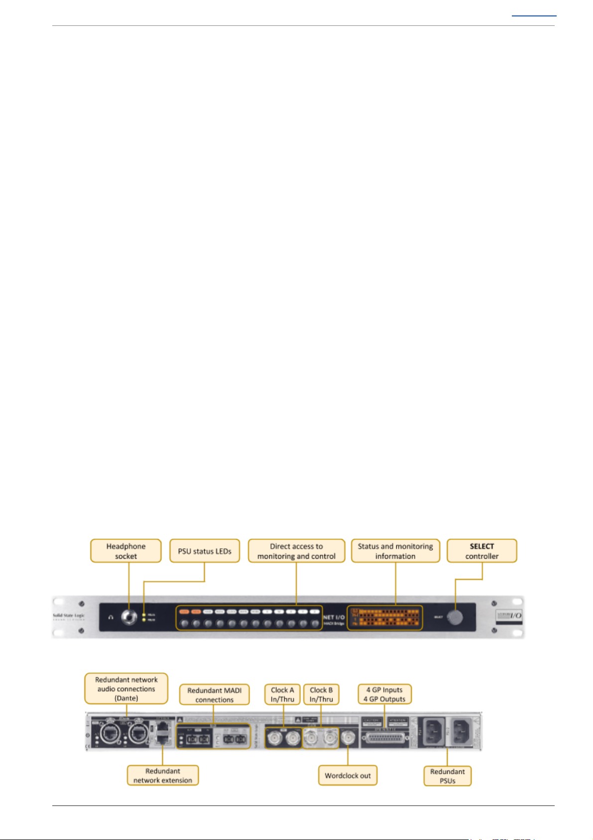
MADI Bridge Front Panel
MADI Bridge Rear Panel
Page 4 of 30
Page 5
MADI Bridge User Guide Contents
Virtual Headphone Patch
Monitoring and signal present metering is provided for incoming and outgoing MADI and Dante
ports. It replaces patchbay based routing with a digital network whilst retaining confidence and fault
finding tools.
Audio Channel Names
The name of the signal (as set in Dante Controller) being transmitted or received over the network
can be displayed in the status and monitoring window for the selected channels.
Page 5 of 30
Page 6
MADI Bridge User Guide Contents
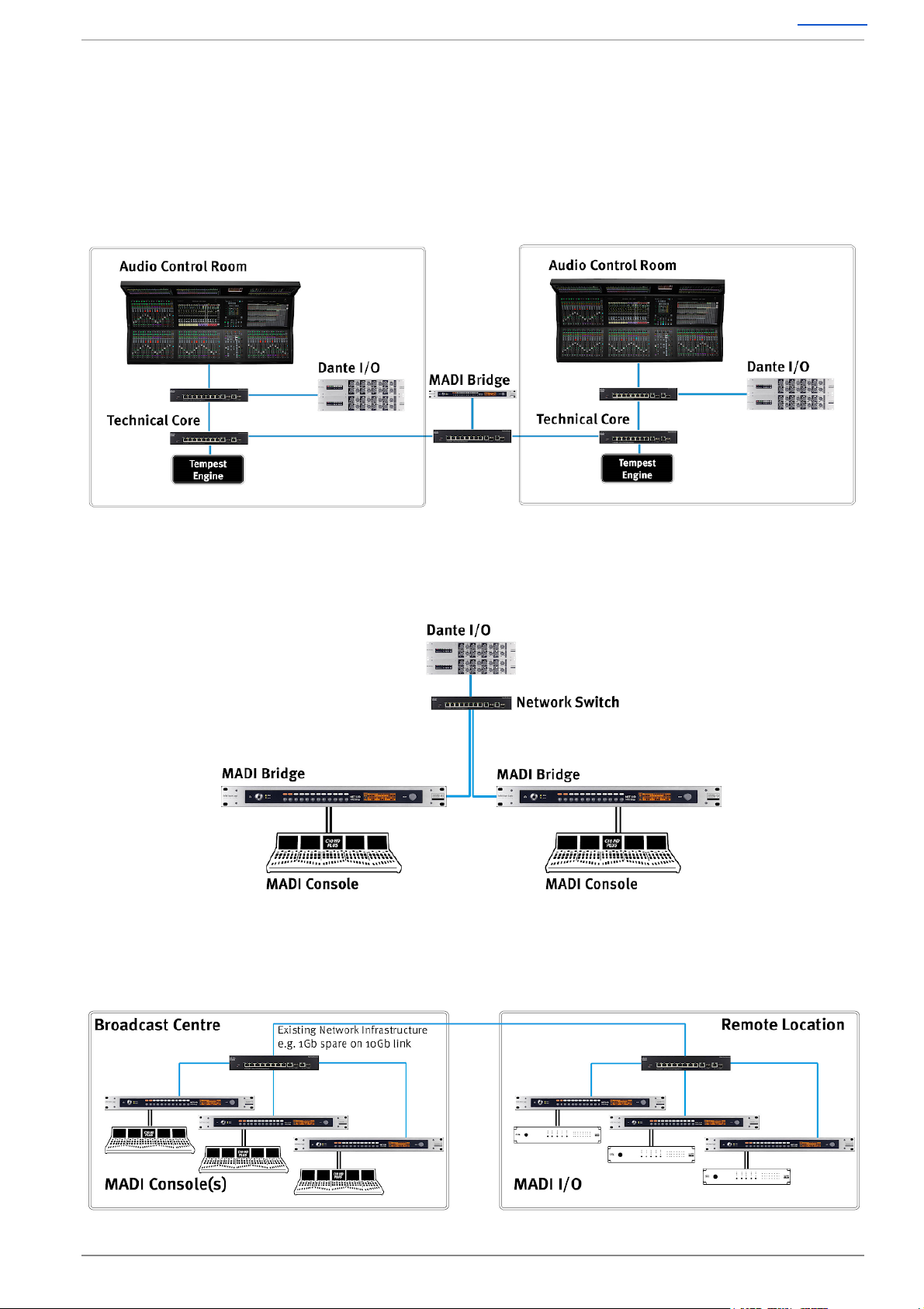
Usage Cases
N.B. The following diagrams omit secondary network connections for clarity.
MADI Connectivity for a System T Network
This provides MADI connectivity available to all networked System T consoles. The MADI Bridge can
also be used as a clock master for the Dante network or to provide external TDM devices with a
clock source.
Dante Network I/O Integration for MADI Consoles
This allows the addition of Dante networked devices to existing MADI infrastructure.
Leveraging Existing Network Infrastructure
Up to 8 MADI streams can be transmitted through 1Gb bandwidth - 512 channels at 48 kHz in each
direction.
Page 6 of 30
Page 7
MADI Bridge User Guide Contents
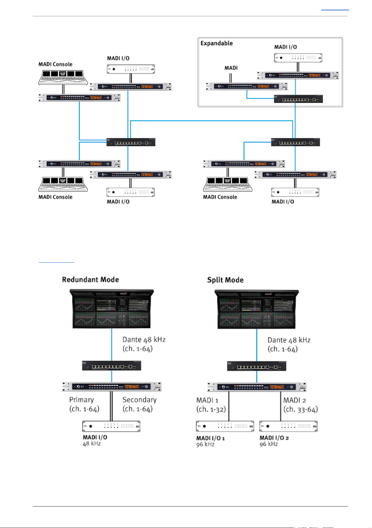
Building a Distributed and Expandable MADI Router
Redundant or Split Mode MADI
The secondary MADI input can be used as a redundant backup of the primary input, or as a second
MADI input when in Split Mode. Here the MADI channel allocation is divided between the ports,
dependant on the MADI and Dante sample rates. Full Split Mode channel allocation details are shown
in Appendix C .
Page 7 of 30
Page 8
MADI Bridge User Guide Contents
Hardware Connections
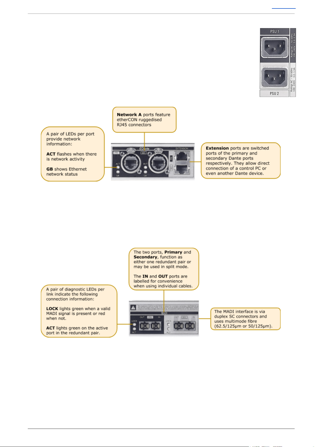
Mains Power Connections
The MADI Bridge includes redundant PSUs with IEC connectors; either supply can
individually power the unit. Ideally these should be connected to separate power
circuits to provide redundancy of incoming AC power.
Dante Connections
MADI Bridge has two redundant sets of network connections.
Note: Some Dante devices allow Dante ports to be set to Switched mode rather than Redundant
mode. MADI Bridge uses the extension ports to provide this functionality, without loss of
redundancy.
Never connect Primary and Secondary ports to the same single Dante network.
MADI
Page 8 of 30
Page 9

MADI Bridge User Guide Contents
Clock
See CLOCK for setup details and Clocking Scenarios for additional information.
GPIO
4 General Purpose opto-coupled inputs and 4 General Purpose relay
outputs allow embedding and de-embedding of logic signals across the
network.
See Appendix D for pinout information.
Page 9 of 30
Page 10

MADI Bridge User Guide Contents
Software Features
The front panel interface is designed to be intuitive to allow access to any function that needs to
change using minimal button presses. Each menu has its own individual radio button that navigates
to the desired page on the OLED. The other front panel control is the SELECT encoder which can be
rotated, pushed or pushed-and-held.
Info Menus
The info menus are accessed by individual buttons to instantly navigate to the desired settings page
on the OLED display. These menus are:
LOCK – Front panel lockout and device information
MON – Metering and headphone monitoring
LOCK
The LOCK button is dual function: it both locks the front panel and displays the info screen on the
OLED Display. MADI Bridge automatically locks-out the front panel after 60 seconds of the SELECT
encoder or button inactivity. After a total of 2 minutes of inactivity the OLED display enters a
screensaver mode. To unlock the front panel, press and hold the LOCK button for 3 seconds. When
already in the LOCK menu, pressing and holding the LOCK button for 3 seconds will lock the front
panel.
Note that the Monitor ( MON ) menu remains accessible even whilst in front panel lockout.
N.B. Holding both the LOCK and Z buttons together for 3 seconds restarts the MADI Bridge.
The default Info page shows the following information:
Page 10 of 30
Page 11

MADI Bridge User Guide Contents
Turning the SELECT encoder scrolls through the info pages:
MON
Pressing the MON button brings up the Monitor menu or Channel Name page. Press the MON
button again to navigate between these pages. The chosen page will be remembered when
navigating to the MON page in future.
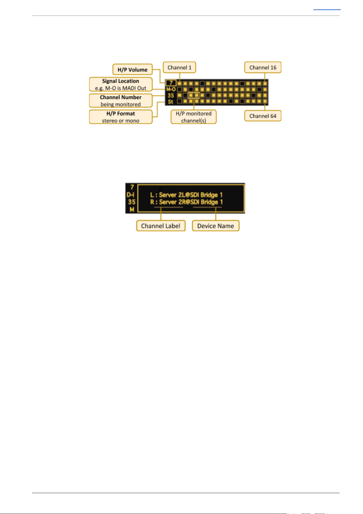
When in the Monitor menu, rotating the SELECT encoder alters the parameter highlighted by the
focus box on the left. Pushing the encoder scrolls down through the 4 options. These options are:
● Headphone volume
● Signal location
● Channel number
● Format
By default when entering the monitoring page the encoder will adjust the headphone volume.
Pressing the SELECT encoder will move the focus to alter Signal Location . The options are:
● M-I MADI Input
● M-O MADI Output
● D-I Dante Input
● D-O Dante Output
When Channel Number is in the focus box rotating the
encoder moves through the channels. This is displayed both
by the channel number and the focus box around the signal
present meters.
Format. When a Stereo channel is selected the left channel
number is displayed and the focus box surrounds 2 signal
present meters.
The Channel Name view displays the ‘Channel Label’ name
as entered in Dante Controller. When looking at D-I or M-O
the name displayed will be the channel label and the device
that is routed to the unit across the network.
Page 11 of 30
Page 12

MADI Bridge User Guide Contents
Options Menus
The Options menus include parameters to be changed from the front panel and display information
that needs to be known when changing options. These menus are:
The Options menus are accessed by individual buttons to instantly navigate to the desired settings
page on the OLED Display. The front panel must be unlocked for these buttons to function.
Within each Options menu the OLED display is divided into four focus sections:
The lower half of each focus box displays the option to be changed, the upper half displays the
parameter it is currently set to. Turning the SELECT encoder moves the focus window across the 4
sections.
The action taken when pressing the SELECT encoder differs depending on the colour of the box in
the lower half of the focus window: a yellow option toggles through the parameters, a grey option
requires a press and hold (3 seconds) to engage a detect routine or to force a special state, a solid
black option indicates information only ( SELECT has no function).
Error Indication
Errors will cause the appropriate Options menu button LED to flash, indicating which menu needs
attention or where information relating to the error’s cause can be found. If an error occurs the
MADI Bridge front panel will automatically unlock and be prevented from entering the screensaver
mode until the the error is resolved. Causes for error indication are shown in the following REDU ,
CLOCK and SRATE sections.
Page 12 of 30
Page 13

MADI Bridge User Guide Contents
MADI
The MADI menu allows you to set the MADI settings. This is used to match the MADI parameters
with those of another MADI device for valid interoperability.
Pressing the MADI menu button brings up the MADI menu. With
the focus box selected to MADI Mode , pressing the encoder
cycles through the MADI mode options ( Auto , 64ch , 56ch , 32ch ,
28ch , 16ch , 14ch ).
The options available depend on the MADI sample rate.
● MADI sample rates of 192 or 176.4 kHz allow 14 or 16
channel mode
● MADI sample rates of 96 or 88.2 kHz allow 28 or 32
channel mode
● MADI sample rates of 48 or 44.1 kHz allow 56 or 64
channel mode
● Auto mode will detect the format of the incoming MADI
stream and display the channel number
● Auto mode will display ERROR if the channel mode cannot be determined
Legacy (SMUX) format MADI at 192, 96 or 88.2 kHz is not supported.
N.B. It is not advised to use two devices with auto-detect modes
at either end of a MADI link.
Turning the encoder clockwise moves the yellow focus box to the
SRC option. Pressing the encoder toggles the sample rate
converters on and off.
In the MADI SRATE window pressing the encoder has no
function. The MADI sample rate is derived from the primary clock
input – see CLOCK and SRATE menus.
The fourth focus window shows MADI R State as displayed in the
REDU menu.
N.B. The MADI Tx continues to function when a MADI Rx signal is not received. While this is a
perfectly usable state for some scenarios, the units error flagging will treat this as an error as there
is no MADI Rx signal. When in this state:
● The front panel will show an error as there is no valid MADI Rx signal
● The unit will not lock the front panel buttons
● The unit's OLED will not enter screen saver mode
● The Monitoring feature will be unavailable for all signal points: MADI In, MADI Out, Dante In
and Dante out
Page 13 of 30
Page 14

MADI Bridge User Guide Contents
REDU
The REDU (Redundancy) menu allows you to set up the MADI redundancy options when interfacing
various MADI devices. In addition, it provides fault-finding tools to continuity-check the validity of
MADI signals directly from the front panel, or instigate Forced Override should you need to override
the automatic redundancy mode.
Pressing the REDU menu button brings up the MADI Redund
Mode Options Menu. With the focus box selected on Redund
Mode pressing the encoder toggles through the options:
● SSL – SSL mode is for integration with SSL consoles that
turn off the MADI signal on the dormant port
○ The REDU LED will flash if you are in SSL Mode
(Dark Fibre) and both MADI inputs are valid
● GPI – The Bridge defaults to the primary MADI input but
can be forced to the secondary by triggering GP input 1
For GPIO pinouts refer to Appendix D .
● None – The MADI ports are now in Split Mode
None (Split) mode is not available at 176.4 or 192 kHz
sample rates. For channel allocation details refer to Appendix C .
Turning SELECT clockwise moves the focus box to the MADI R
State option, pressing SELECT has no function. The option reports
the MADI redundancy state and as such the MADI input bridged to
Dante ( Pri , Sec , Pri Error , Split Mode ).
When in GPI mode this reports the GPI state. When in SSL mode
this reports the active MADI port or, if both are active reports Pri
Error , as one MADI connection should be ‘dark’. In SSL mode, if
neither port is active, the unit defaults to the primary port.
Turning SELECT clockwise moves the focus box to Pri MADI Rx ,
this option is primarily for reporting only. However, for fault-finding
and recovery this can be used to force MADI to the primary port.
Pressing and holding SELECT for 3 seconds will put the MADI
Bridge into Force Primary Override mode.
While in this state the display will say Force and the REDU menu
LED will flash to warn that Force mode has been enabled. Pressing
and holding SELECT again for 3 seconds will revert to normal
operation.
There is also a Force Secondary Port Override option when focus is
on Sec MADI Rx . Press and hold SELECT for 3 seconds to engage
and revert to standard.
Page 14 of 30
Page 15

MADI Bridge User Guide Contents
CLOCK
The CLOCK menu allows you to set the primary and secondary clock sources and enable the Auto
Detect routine for each source.
Pressing the CLOCK menu button brings up the Clock page. With
Pri Clk in the focus window pressing the SELECT encoder cycles
through the clock options ( Ext A , MADI , Dante ).
The clock source selected in Pri Clk is not enabled until the Auto
Detect routine is enabled in Pri Detect .
Turning SELECT clockwise moves the focus box to Primary Detect.
Pressing and holding SELECT for 3 seconds starts the auto detect
routine; this lasts for 20 seconds.
When Ext A is the Pri Clk source the Auto Detect will determine if
the attached clock is video or wordclock. If the source is wordclock
it will determine the sample rate; if the source is video the video
sample rate will need to be set in the SRATE menu.
Turning SELECT again moves the focus to Sec Clk , pressing
SELECT cycles through the options ( Ext B , MADI , Dante , None ).
None should be used to disable the secondary clock input if
nothing is required.
Again the secondary clock Auto Detect routine can be enabled by
pressing and holding the SELECT encoder when Sec Detect is in
focus.
N.B. With SRC on, the clocking options do not include Dante. Dante clocking is determined in Dante
Controller.
The CLOCK LED will flash if the MADI Bridge has swapped over to the secondary clock. A manual
detection of the primary clock is needed to force it to the primary clock.
Page 15 of 30
Page 16

MADI Bridge User Guide Contents
SRATE
Sample rate reporting and setting if using video sync.
Pressing the SRATE menu button brings up the Sample Rate
menu. If the primary clock is MADI, Dante or wordclock it
automatically detects the sample rate using the primary clock Auto
Detect routine in the CLOCK menu.
If the primary clock source is video this option becomes manual
(signified by being highlighted yellow) – pressing SELECT toggles
through the sample rate options ( 44.1 , 48 , 88.2 , 96 , 176.4 and
192 kHz).
Turning SELECT clockwise moves the focus box to Sec Clk Info .
If the secondary clock is MADI, Dante or wordclock it automatically
detects the sample rate using the secondary clock Auto Detect
routine enabled in the CLOCK menu.
If the secondary clock source is video this option becomes manual
(signified by being highlighted yellow) – pressing SELECT toggles
through the sample rate options ( 44.1 , 48 , 88.2 , 96 , 176.4 and
192 kHz).
With the focus box on MADI Info the encoder has no function, the
MADI Info sample rate follows that of the primary clock sample
rate.
With the focus box on Dante Info the encoder has no function,
Dante Info reports the Dante sample rate set for the MADI Bridge
from Dante Controller.
The SRATE LED will flash if the sample rates do not match and SRC is switched off.
Page 16 of 30
Page 17

MADI Bridge User Guide Contents
MODE
The MODE menu allows you to set the Control Mode . The Control Mode setting is required when
AES user and control bits are to be transported between devices on the Dante network.
N.B. On older design MADI Bridge devices the MODE button is labelled U .
To enable the pass-through of AES user and control bits the MADI Bridge must be set to PCM 32
encoding within Dante Controller. Changing the encoding setting is detailed in the Dante Controller
section of this guide.
N.B. When set to 32-bit encoding the audio remains 24-bit. The additional 8 bits are used to
transport the user and control bits from the AES10 signal.
Pressing the MODE menu button brings up the Control Mode page. If 32-bit encoding is enabled
then pressing the SELECT encoder cycles through the available options ( SSL , AES10 ).
● SSL mode is for use with SSL devices such as the
Alpha-Link LIVE - control data is transferred in the upper
audio channels
N.B. For SSL Control Mode (and any other manufacturers’
control modes using higher audio channels and user bits for
control) all audio channels must be routed one-to-one
between the two MADI Bridge devices.
● AES10 mode enables transparent pass-through of the user
and control bits from the signal
If the MADI Bridge is set to PCM 24 encoding the Control Mode
will be fixed to None . No user or control bits will be passed
through.
Page 17 of 30
Page 18

MADI Bridge User Guide Contents
Dante Controller
Refer to Audinate’s Dante Controller user guide for complete information on Dante Controller
software. The information below details the basics required to get started.
Clock sync, device naming and network management are all done within Dante Controller.
Dante utilises the device name for routing. Each device must have a unique name – if a name is
duplicated it will be appended with a number.
Network Config
Each device requires its own unique IP address. This may be automatically configured, provided by a
DHCP server or assigned manually. The primary and secondary ports must not be connected to the
same logical network. Ideally, separate switching hardware should be provided for primary and
secondary networks. Creating VLANs on shared hardware is acceptable but does not provide the
most robust redundancy.
The Default display in the LOCK mode shows the primary IP address; in this way you will always be
able to access the device regardless of what mode the network ports are set to.
Device Info
The Device Info tab shows an overview of all devices on the Dante network including name,
product type, software version, IP address, link speed and status.
Device > Device View provides configuration and diagnostics for each device including Tx and Rx
subscription and signal status, software and firmware version information, network utilisation and
real-time latency measurement, as well as configuration of device name, sample rate, bit depth,
latency, IP address and AES67 parameters. The Network Config tab provides IP address
configuration options.
The device will resolve to a link-local address if it is set to obtain an IP address automatically and no
DHCP server is present. To access via link-local, set your computer to obtain an IP address
automatically, directly connect to the device’s primary port and wait for the link-local addresses to
resolve. Link-local addresses for the Primary Dante interfaces obtain IP addresses in the
169.254.xxx.xxx range, secondary Dante interfaces obtain addresses in the 172.31.xxx.xxx range.
Page 18 of 30
Page 19

MADI Bridge User Guide Contents
User and Control Bit Pass-Through
To enable the pass-through of AES user and control bits the device must be set to 32-bit encoding
( PCM 32 ). This is set within the Encoding section of the Device Config tab.
Brooklyn Reset
Resetting the Dante Brooklyn card to default settings is performed from Dante Controller. Under the
Device Config tab for a device select Clear Config . This clears the device name, channel labels, IP
address settings, sample rate, latency and existing audio routes.
Page 19 of 30
Page 20

MADI Bridge User Guide Contents
Clocking Scenarios
Network of Consoles With House Sync
This setup shows a network containing multiple consoles. Two are shown but the principles would
remain the same for a larger network. House synchronisation is provided to multiple MADI Bridge
devices, these are set to ‘Enable sync to external’ within Dante Controller. This provides the network
with redundant master clock sources referenced to the house synchronisation. One device would be
elected as the Grand Master Clock for the Dante network, if that were to fail another MADI Bridge
would take the role of Grand Master.
Clocking from the Network
In this example a MADI Bridge receives a redundant external sync signal. This MADI Bridge is set to
Sync to External within Dante Controller. The remaining MADI Bridges will derive their own clock
from the master device. This can be fed to external TDM devices using the MADI Bridge wordclock
outputs.
Page 20 of 30
Page 21

MADI Bridge User Guide Contents
Appendices
Appendix A – Specifications
Physical
Parameter
Value
Notes
Depth
200mm ( 7.75")
Height
44.5mm ( 1.75")
1 RU
Width
438mm ( 17.25")
482mm ( 19")
Excluding rack ears
Including rack ears
Weight
3.1kg ( 6.8 lb)
Power
< 20 W
Boxed Size
630 x 310 x 130mm ( 25 x 12 x 5.5")
Boxed Weight
4kg ( 8.8 lb)
Ventilation
Ventilation is from the side of the unit.
Group Delay
Parameter
Value
Notes
Group delay (no SRC)
8 samples
MADI to Dante module*
Group delay (with SRC)
51 samples
MADI to Dante module*
*Group delay does not include the deterministic Dante device latency which can be specified in
Dante Controller.
Page 21 of 30
Page 22

MADI Bridge User Guide Contents
Appendix B - Supported Sync Rates
Video Format
Field Rate (Hz)
Frame Rate (Hz)
Notes
PAL
50
25
SD
PAL 24
48
24
NTSC
59.94
29.97
1080i 60 Hz
60
30
HD
1080i 59.94 Hz
59.94
29.97
1080i 50Hz
50
25
1080p 60 Hz
60
60
1080p 59.94 Hz
59.94
59.94
1080p 50 Hz
50
50
1080p 30 Hz
30
30
1080p 29.97 Hz
29.97
29.97
1080p 25 Hz
25
25
1080p 24 Hz
24
24
1080p 23.976 Hz
23.976
23.976
1080PsF 24 Hz (1080i 48 Hz)
24
24
1080PsF 23.976 Hz (1080i 47.95 Hz)
23.976
23.976
720p 60 Hz
60
60
720p 59.94 Hz
59.94
59.94
720p 50 Hz
50
50
Unsupported Rates
Video Format
Field Rate (Hz)
PAL
23.976
720p
30
720p
29.97
720p
25
720p
24
720p
23.976
Page 22 of 30
Page 23

MADI Bridge User Guide Contents
Appendix C - MADI Split Monitoring
The following diagrams show the number of MADI channels available –
and the associated front panel displays – for each setting of MADI
sample rate, Dante sample rate, channel count and split/redundant
mode.
The diagram to the right indicates the number of channel slots available
for audio (or silence) in each operating mode.
* SRC can be on or off.
† In split mode operation the break between the channels is indicated by the dotted line – the first
channel of the lower section becomes channel 33 or 29 and is the start of the secondary MADI port.
The channel number mapping between MADI and Dante always follows the channel numbers.
Page 23 of 30
Page 24

MADI Bridge User Guide Contents
* SRC can be on or off.
Page 24 of 30
Page 25

MADI Bridge User Guide Contents
* SRC can be on or off.
Page 25 of 30
Page 26

MADI Bridge User Guide Contents
The following table shows the number of MADI channels available for each setting of Dante sample
rate, MADI sample rate, channel count and split/redundant mode.
Dante
Sample
Rate (kHz)
Dante
Channel
Count
MADI
Sample
Rate (kHz)
MADI
Channel
Count
MADI
Redundancy
State
Channels Transmitted
from MADI Primary
Channels Transmitted
From MADI Secondary
44.1/48
64
44.1/48
64
Redundant
64
64*
56
Redundant
56
56*
64
Split
32
32
56
Split
28
28
88.2/96
32
Redundant
32
32*
28
Redundant
28
28*
32
Split
32
32
28
Split
28
28
176.4/192
16
Redundant
16
16*
14
Redundant
14
14*
88.2/96
32
44.1/48
64
Redundant
32
32*
56
Redundant
32
32*
64
Split
32
0
56
Split
32
0
88.2/96
32
Redundant
32
32*
28
Redundant
28
28*
32
Split
32
0
28
Split
28
4
176.4/192
16
Redundant
16
16*
14
Redundant
14
14*
176.4/192
16
44.1/48
64
Redundant
16
16*
56
Redundant
16
16*
64
Split
16
0
56
Split
16
0
88.2/96
32
Redundant
16
16*
28
Redundant
16
16*
32
Split
16
0
28
Split
16
0
176.4/192
16
Redundant
16
16*
14
Redundant
14
14*
* The secondary MADI port is a redundant backup to the primary MADI port. These channels will
replace the primary MADI port channels in the event of a failure/manual changeover to the
secondary MADI port.
Page 26 of 30
Page 27

MADI Bridge User Guide Contents
Appendix D - GPIO Pinouts
GP Outputs
All output switch closures are via DIL relay.
DO NOT use these outputs to directly switch capacitive or reactive loads; always use a separate
external relay with suitable contact rating.
DIL Relay Ratings:
• 100V DC, 125V AC
• 100mA max.
GP Inputs
Inputs are triggered by applying an AC or DC voltage of between 4V and 24V. The current drawn is
approximately 10mA. Minimum input pulse duration 50mS.
GP Inputs / Outputs
Connector Type: 25-way D-type male
Pin
Description
Notes:
1
14
2
15
3
16
4
17
5
18
6
19
7
20
8
21
9
22
10
23
11
24
12
25
13
Input 1A
Input 1B
Input 2A
Input 2B
Input 3A
Input 3B
Input 4A
Input 4B
+12V Output
Chassis
Output 1A
Output 1B
Output 2A
Output 2B
Output 3A
Output 3B
Output 4A
Output 4B
+12V Output
See input requirements above
0.5A max (both pins), Linked to pin 13
Reference for 12V output
See contact rangs above
As pin 7
Page 27 of 30
Page 28

MADI Bridge User Guide Contents
Appendix E – Safety Notices
General Safety
1.
Please read and keep this document.
2.
Adhere to all warnings and follow instructions.
3.
This electrical equipment should not be used near water.
4.
Cleaning should only be with dry cloths or products compatible with electrical devices –
never when the unit is powered.
5.
Keep the unit free of dust and use in a clean environment.
6.
Do not use near any heat source or in direct sunlight.
7.
Do not use near naked flames.
8.
Do not place heavy objects on the unit.
9.
Only use attachments/accessories recommended by the manufacturer.
10.
Unplug the device during lightning storms or long periods of nonuse.
11.
The unit can only be serviced by qualified personnel – Seek immediate service if:
I. The unit has been exposed to moisture
II. The unit has been dropped
III. The unit does not operate normally
12.
Do NOT modify this unit – alterations may affect performance, safety and/or international
compliance standards.
13.
SSL does not accept liability for damage caused by maintenance, repair or modification by
unauthorised personnel.
Installation Notes
1.
When installing this apparatus either fix it into a standard 19” rack or place the apparatus
on a secure level surface.
2.
When this apparatus is rack mounted, fit all rack screws. Rack shelves are recommended
for this apparatus.
3.
Allow a 1U gap above and below this apparatus for cooling.
4.
Do not obstruct any ventilation cut-outs or exhaust fans.
5.
Ensure that no strain is placed on any cables connected to this apparatus. Ensure that all
such cables are not placed where they can be stepped on, pulled or tripped over.
Page 28 of 30
Page 29

MADI Bridge User Guide Contents
Power Safety
1.
The unit is not supplied with a mains lead allowing you to use IEC distribution of mains
cables of your choice. Any mains cable used must fulfill the following:
I. Refer to the ratings label on the rear of the unit and always use suitable mains
cords.
II. The unit should ALWAYS be earthed with the earth on both IEC sockets (when both
are used).
III. Please use a compliant 60320 C13 TYPE SOCKET. When connecting to supply outlets
ensure that appropriate sized conductors and plugs are used to suit local electrical
requirements.
IV. Maximum cord length should be 4.5m (15’).
V. The cord should bear the approval mark of the country in which it is to be used.
2.
The appliance coupler is used as the disconnect device, ensure that it is connected to an
unobstructed wall outlet.
3.
The unit is designed for connection to single phase supplies only.
4.
The clear markings regarding redundant power supplies detailed on the unit must be
transferred into the installation to ensure both power sources are removed before qualified
personnel service the unit.
GB
The apparatus shall be connected to mains socket outlets with a protective earthing
connection
DEN
Apparatets stikprop skal tilsluttes en stikkontakt med jord, som giver forbindelse til
stikproppens jord
FIN
Laite on liitettävä suojamaadoituskoskettimilla va rustettuumpistorasiaan
NOR
Apparatet må tikoples jordet stikkontakt
SWE
Apparaten skall anslutas till jordat uttag
ATTENTION ! This equipment must be Earthed. Refer to manual for installation
instructions.
CAUTION ! Disconnect all power sources before removing any panel (s). No
user-serviceable parts inside – to be serviced only by qualified personnel.
WARNING ! Un-Earthed metal parts may be present inside enclosure. Check for
hazardous voltages before touching.
For protection against risk of fire – replace only with same type / rating of fuse. Do
not expose to rain or moisture.
For EU
The stagebox is CE compliant and fully conforms with the current protection requirements
of the European community council directives on EMC and LVD. Note that any cables
supplied with SSL equipment may be fitted with ferrite rings at each end. This is to comply
with the current regulations and these ferrites should not be removed. Any modifications
to this equipment may adversely affect the CE compliance of this product.
Page 29 of 30
Page 30

MADI Bridge User Guide Contents
Environmental Declaration
The symbol shown here, which is on the product or its packaging, indicates that this
product must not be disposed of with other waste. Instead, it is the user’s responsibility to
dispose of their waste using a designated collection point for recycling of waste electrical
and electronic equipment. The separate collection and recycling of your waste equipment
at the time of disposal will help to conserve natural resources and ensure that it is
recycled in a manner that protects human health and the environment. For more
information about where you can dispose of your waste equipment for recycling, please contact your
local city office, your household waste disposal service or where you purchased the product.
RoHS Notice
Solid State Logic has conformed and this product has conformed to European Union’s Directive
2011/65/EU on Restrictions of Hazardous Substances (RoHS) as well as the following sections of
California law which refer to RoHS, namely sections 25214.10, 25214.10.2, and 58012, Health and
Safety Code; Section 42475.2, Public Resources Code.
For USA
To the User:
1. Do not modify this unit! This product, when installed as indicated in the instructions
contained in the installation manual, meets FCC requirements.
2. Important: This product satisfies FCC regulations when high quality shielded cables are used
to connect with other equipment. Failure to use high quality shielded cables or to follow the
installation instructions may cause magnetic interference with appliances such as radios and
televisions and will void your FCC authorisation to use this product in the USA.
3. Note: This equipment has been tested and found to comply with the limits for a Class A
digital device, pursuant to part 15 of the FCC Rules. These limits are designed to provide
reasonable protection against harmful interference when the equipment is operated in a
commercial environment. This equipment generates, uses, and can radiate radio frequency
energy and, if not installed and used in accordance with the instruction manual, may cause
harmful interference to radio communications. Operation of this equipment in a residential
area is likely to cause harmful interference in which case the user will be required to correct
the interference at his own expense.
Electromagnetic Compatibility
EN55103-1:2009, EN55103-2:2009 Environments E1, E2, E3 and E4
Initial inrush current: 0.5A, 5 sec inrush current: 0.5A
To maintain electromagnetic compatibility SSL recommends using shielded and foiled twisted pair
Ethernet cables of Cat 5e standard or above where applicable.
Environmental
Temperature
Operating:
+5 to 40 deg. C
Storage:
-20 to 50 deg. C
Relative
Humidity
Operating:
20 to 80% humidity
Max. wet bulb: 29 deg. C
(non-condensing)
Storage:
5 to 90%
Vibration
Operating:
< 0.2 G (3–100 Hz)
Non-operating:
< 0.4 G (3–100 Hz)
Shock
Operating:
< 2 G (10 ms max.)
Non-operating:
< 10 G (10 ms max.)
Altitude
Operating
0 to 3000m
(above sea level)
Non-operating:
0 to 12000m
Page 30 of 30
 Loading...