

Solid State Logic Live L100, Live L350, L500 Plus, Live L300, Live L500 Installation Manual
...Page 1

Installation Guide
Part no. 82BL5G01J
Page 2
SSL Live Installation Information
Document Revision History
V4.8
January 2019
V4.7
July 2018
V4.5
Dec 2017
V4.0
May 2017
Contents
Maintenance: Dust Guards 4
Live Console Synchronisation & Clocking 4
Clocking in General 4
Selecting a Clock Source 4
Clocking via a Blacklight II Concentrator 5
Clocking over Dante 5
Clocking over a BLII/X-Light Bridge 6
Setting the Sample Rate 7
Clocking MADI Stageboxes 7
Daisy-Chaining MADI Stageboxes 8
AES/EBU Connections 8
L100 Console 10
L100 Connections - Front 10
L100 Console Connections - Rear 10
L100 Console Weight, Power & Dimensions 11
L200 Connections - Front 12
L200 Console Connections - Rear 12
L200 Console Weight, Power & Dimensions 13
L300 & L350 Consoles 14
L300 & L350 Connections - Front 14
L300 & L350 Connections - Rear 14
L300 & L350 Console Weight, Power & Dimensions 15
L500 Plus Console 16
L500 Plus Connections - Front 16
L500 Plus Connections - Rear 16
L500 Plus Console Weight, Power & Dimensions 17
L550 Console 18
L550 Plus Connections - Front 18
L550 Plus Connections - Rear 18
L550 Console Weight, Power & Dimensions 19
Console Remote, Timecode & Sync Panel 20
Remote Tile 21
Remote Tile Weight, Power & Dimensions 21
ML 32.32 5U Mic/Line Stagebox 23
ML I.32 5U Mic/Line Input Stagebox 24
ML O.32 5U Line Output Stagebox 24
ML 32.32 Weight & Dimensions 24
www.solidstatelogic.com Page 2 of 43
Page 3

SSL Live Installation Information
D 32.32 AES Digital 2U Stagebox 25
D 32.32 Weight & Dimensions 25
BLII.D 2U Blacklight-MADI Concentrator 26
BLII.D Weight & Dimensions 26
Net I/O BLII Bridge - Blacklight II to Dante Bridge 27
BLII Bridge Weight & Dimensions 27
Net I/O X-Light Bridge 28
X-Light Bridge Weight & Dimensions 28
Connections - Key 29
Typical Installation Diagrams 37
Simple Single System 37
Blacklight II Single System (with Redundancy) 38
Dual Console MADI System 39
Dual Console System with Blacklight from each console 40
Optional Console Stand 41
L500 / L500 Plus / L550 (SSL part 62A7000XL) 41
L300 / L350 (SSL part 62A7300XL) 42
www.solidstatelogic.com Page 3 of 43
Page 4
SSL Live Installation Information
Maintenance: Dust Guards
Your Live Console may be fitted with dust guards covering the air vents beneath the faders. It is
recommended that the filter foam should be regularly inspected for particular buildup.
Unscrew the M3 screws that secure the dust guards in place and inspect both sides of the guard. If
necessary, vacuum clean. Extremely dirty filters may be cleaned with water and replaced when dry.
Filter pads may last several years before needing replacement. Please contact SSL for replacement
filter pads.
Live Console Synchronisation & Clocking
The Live console and associated stageboxes are connected digitally and thus must share a common
digital clock (sync) source. This section describes how to set up a Live system with multiple
stageboxes and multiple consoles successfully, using both internal and external clock sources.
Clocking in General
The Live console has a very high quality internal clock that can be used to clock an entire system with
multiple Live consoles and stageboxes connected, so no external clock source is needed unless a
specific application requires it. If there is a specific requirement for external clocking of a Live system,
the external clock must match the sample rate at which the Live console is running (or PAL 25/NTSC
29.97 video sync).
Note: It is also important that, if an external clock is used, only the Live console should be connected
to the clock source. SSL Live stageboxes will receive their clock via the MADI stream from the
console. We do not recommend connecting external clocks to each of the stageboxes in this
configuration.
ALL AES/EBU connections on the console and D32.32 stageboxes have sample rate converters and
can accommodate digital devices at alternative sample rates, or those running in a different clock
domain. The AES/EBU connection options and set up are detailed below.
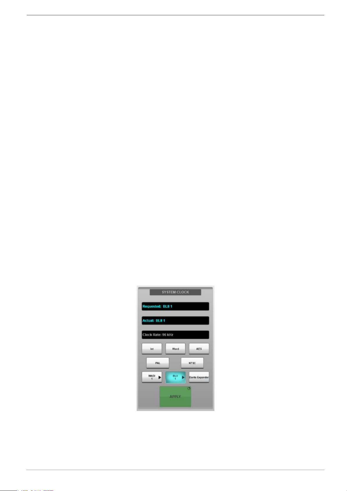
Selecting a Clock Source
The console can be clocked internally, or externally via video, AES, wordclock, MADI, Blacklight II or
Dante Expander. This is set from MENU > Setup > Options > SYSTEM tab:
Select the required clock source (if MADI or Blacklight II, press the button again and select which
MADI/Blacklight port to use from the drop down menu) then press & hold the APPLY button. Ensure
that the “Requested” and “Actual” sources match.
www.solidstatelogic.com Page 4 of 43
Page 5

SSL Live Installation Information
If the clock source is lost, the console will try other clock sources in this sequence: BLII, MADI, video,
AES, wordclock, internal, until it finds a valid clock. The original but lost source will need to be
manually re-selected and applied once it has been reconnected - it will not switch clocks back and
forth automatically in case of an intermittent clock source.
The status bar at the top of the main screen will show a clock source change to warn the operator.
Clocking via a Blacklight II Concentrator
Two consoles may be connected to a Blacklight II Concentrator for sharing a set of stageboxes. The
'Master' console (designated as such by connecting to the Blacklight Concentrator's A ports) will
distribute its clock to the Blacklight system and any stageboxes and consoles connected to it. The
'Slave' console (designated by connecting to the Blacklight Concentrator's B ports) should therefore
set its clock source to the corresponding BLII port on the rear of the console.
The Master console should distribute either its internal clock over Blacklight II (by selecting the Int
option), or one of the external clock source options listed above, with the exception of any Blacklight
port of which it is the Master. Selecting the BLII clock source button will reveal a subset of buttons.
The Slave console should use the Blacklight II option. However, the Master console may use one of
the MADI options if an external MADI source is connected to the corresponding MADI input on the
Blacklight Concentrator. This could be a MADI feed from a third party device providing clock, or
wordlock via a stagebox set to its external wordclock input.
Clocking over Dante
Before proceeding, ensure that the console’s Dante Expander Module, and BLII/X-Light Bridge if
applicable, and any stageboxes or other Dante devices appear in black text in Dante Controller. If the
devices are not visible or visible in red text please see
livehelp.solidstatelogic.com/Help/DanteSetup.html in the SSL Live Help System.
Dante uses its own “Clock Election” process to determine the most appropriate Clock Master for the
Dante network and a Clock Master will be chosen automatically. For more information on the Dante
Clock Election process please see the Audinate website:
dev.audinate.com/GA/dante-controller/userguide/webhelp/#clock_synchronization.htm
To choose a Clock Master manually, set this device to be the “Preferred Master”. To do this, open
Dante Controller and click on the Clock Status tab. Check the “Preferred Master” checkbox for your
chosen Clock Master. This device will become the Clock Master.
If multiple devices on the network are “Preferred Masters”, the Dante Clock Election process will
automatically choose a Clock Master from the multiple “Preferred Masters”.
If the Clock Master’s status changes, or a more suitable Clock Master comes online, the Dante
network will go through the Clock Election steps again to determine the most suitable Clock Master for
the network.
If you are not using Dante network redundancy, please use the primary connection (rather than the
secondary) to ensure accurate synchronisation.
SSL Recommends: SSL recommends that the console is set to clock from the Dante network to
benefit from the Dante clock election process.
Setting up the Console as a Slave of the Dante Network
In this configuration, a Dante device other than the console is the Clock Master. The console and all
other devices on the network will clock to this master.
In Dante Controller, go to the Clock Status tab. Check the “Preferred Master” checkbox for the Clock
Master device(s) if you wish to set one. Dante has its own clock election process, so it is not
necessary to set a Preferred Master. For this example ensure that “Preferred Master” and “Sync to
External” are unchecked for all devices on the network (including the console’s Dante Expander).
On the console, go to MENU > Setup > Options > SYSTEM tab. In the “SYSTEM CLOCK” section,
select Dante Expander and press and hold Apply. Check that both the “Requested” and “Actual”
fields above list “Dante Expander”.
www.solidstatelogic.com Page 5 of 43
Page 6
SSL Live Installation Information
The chosen “Preferred Master” (if set) is now the Clock Master of the network, including the console.
The console is now clocking from its Dante Expander module. The Dante Expander module is clocking
from the “Preferred Master” on the Dante network. All other devices on the network are clocking from
the “Preferred Master” on the Dante network.
Note that if selecting Dante as a clock source on the console, the console’s internal clock source will
not drop back to another clock source if the Dante network clock is lost. The Dante Expander module
incorporates an internal clock which will be become the Clock Master of the Dante network in this
instance until another device on the network is identified as the most suitable Clock Master from the
Clock Election process.
Important: It is not recommended to clock from Dante if the Dante SRC In is engaged.
Consoles clocked from stageboxes via MADI or Wordclock are not recommended to be used as Dante
network Clock Master sources.
Clocking over a BLII/X-Light Bridge
The console can be the Master or the Slave of the Dante Network through the BLII/X-Light Bridge.
Setting up the Console as a Slave of the Dante Network
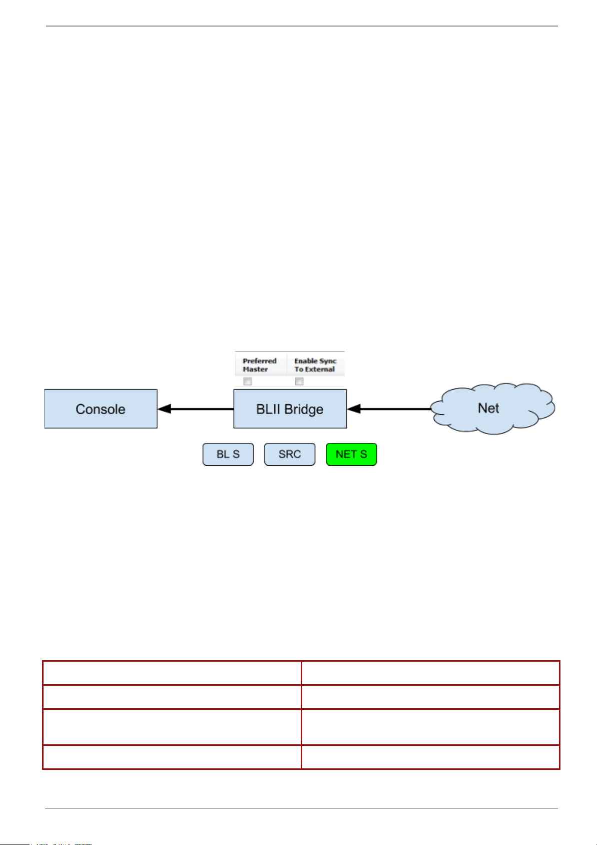
For the most reliable clocking scheme, SSL recommends that the console is set to be a slave of the
Dante network when using a BLII/X-Light Bridge.
In this configuration, a Dante device other than the console is the Clock Master. The BLII/X-Light
Bridge is set to clock from the Dante Network, and the console clocks from the Bridge.
In Dante Controller, go to the Clock Status tab. Check the “Preferred Master” checkbox for the Clock
Master device.
On the console, go to MENU > Setup > Options > SYSTEM tab. In the “SYSTEM CLOCK” section,
select BLII 1 and press and hold Apply. Check that both the “Requested” and “Actual” fields above
list the correct port.
On an L500 Plus or L550 with two pairs of BLII/X-Light ports fitted, select either port 1 or 2
depending on which port has been used to connect to the BLII/X-Light Bridge (On L550 BLII is port 1,
X-Light is port 2). To select port 2, tap the BLII/X-Light 1 button twice and a drop down menu will
appear. Tap 2, then tap Blacklight II if using a BLII Bridge. Check that both the “Requested” and
“Actual” fields above list the correct port.
If configured correctly the following LEDs will be seen on the BLII/X-Light Bridge:
LED
If configured correctly will light
BL S
Off
NET S
Redundant system: Solid Green
Non-redundant system: Flashing Green & Red
GM (BLII Bridge only)
Off
www.solidstatelogic.com Page 6 of 43
Page 7
SSL Live Installation Information
If colours differ from the above please consult the full tables in the SSL Live Help System
livehelp.solidstatelogic.com/Help/DanteBridges.html.
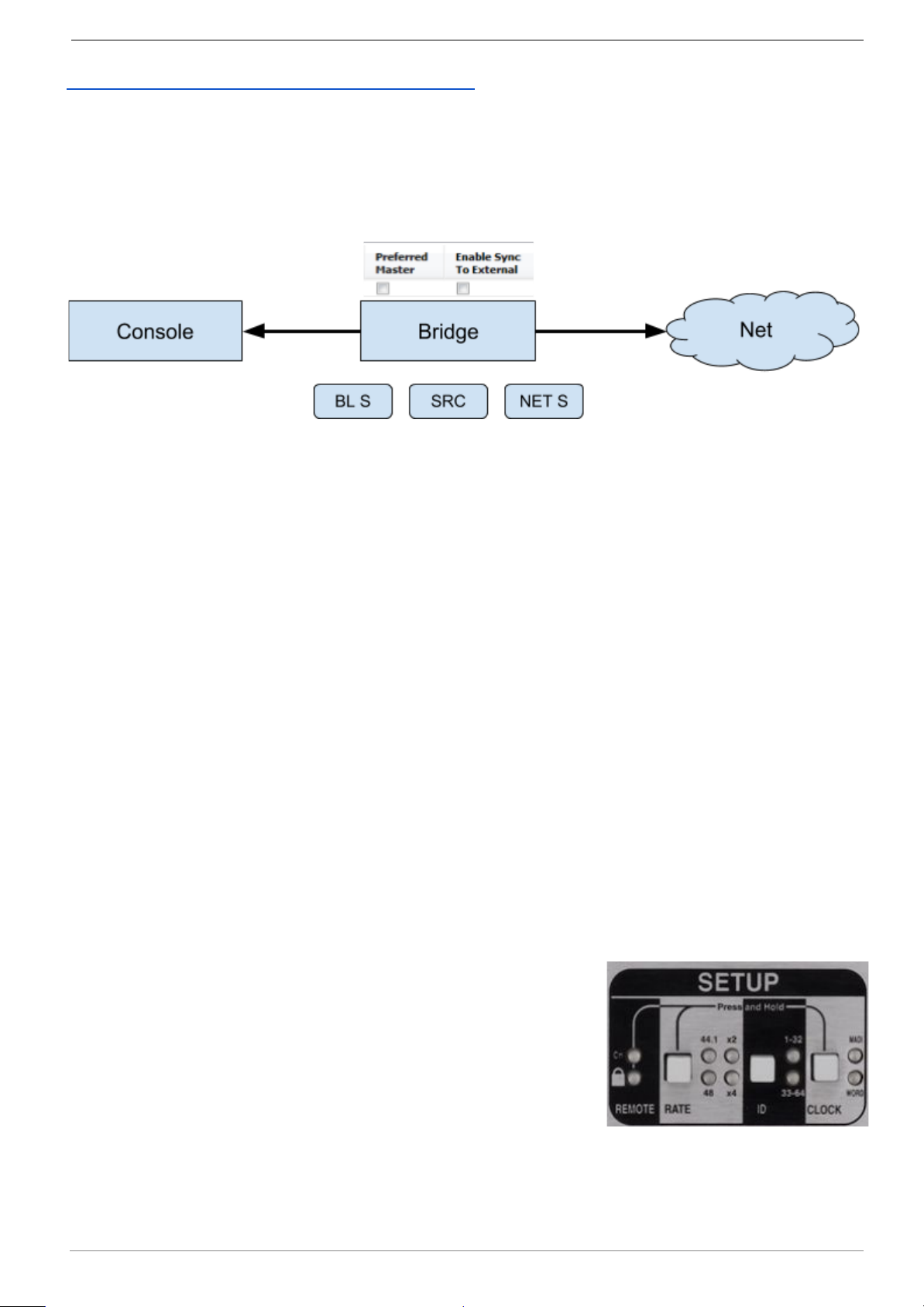
When the BLII/X-Light Bridge becomes the Clock Master
If the BL S and NET S LEDs are off and the GM LED is Solid Green (BLII Bridge only), the BLII/X-Light
Bridge has become the master of the network. This could occur if the console and BLII/X-Light Bridge
were set to clock from a Dante device on the network, but this Clock Master loses connection to the
network. The BLII/X-Light Bridge could then be chosen by the Dante network as the Clock Master of
the Dante network.
This is a perfectly valid clocking scheme. The BLII/X-Light Bridge will now clock the console and the
network from its internal clock. The console’s clock source will remain as Dante.
To manually set the BLII/X-Light Bridge to be the clock master, follow the same steps as configuring
the console to clock from the Dante network, but check the “Preferred Master” box beside the
BLII/X-Light Bridge in Dante Controller.
Setting the Sample Rate
The Live system can run at 96 kHz (recommended) or 48 kHz sample rates. Use the 96 kHz and 48
kHz buttons in the System page (MENU > Setup > SYSTEM) to change the console's sample rate.
The stageboxes must also be changed to match the console's sample rate; see below.
Aside from the FX Loop and optional Dante module interfaces, decreasing the sample rate to 48 kHz
does not increase the total input/output count; each MADI port carries 64 channels at 48 kHz but
odd-even MADI port pairs are always redundant (even-numbered ports on twin card Blacklight
Concentrator are disabled).
Important: Changing the console's sample rate will interrupt audio and cause routes to be dropped
as stagebox configurations will need to be changed. Muting all outputs to switch sample rate and for a
further 30 seconds is recommended.
Important: The console must be rebooted following a change in Sample Rate.
Clocking MADI Stageboxes
By default stageboxes are set to clock from the incoming MADI stream. This is the recommended
setting. Other stagebox clock sync options are internal or external wordclock.
The clock source and sample rate can be set from the physical
setup controls on the rear of each stagebox. The current clock
source is displayed to the right of the SETUP area: if neither clock
LED is lit, the stagebox is running on its own internal clock.
Note: The wordclock output transmits the clock signal currently in
use by the stagebox (i.e. it is not a loop thru), depending on the
stagebox's clock source setting).
To change the clock source, press & hold REMOTE and CLOCK
simultaneously until the padlock flashes green. Press CLOCK until MADI is lit. The colour shows the
following:
● Red: no MADI from master console detected.
● Red/green flashing: a single master MADI port is locked (non-redundant cabling).
www.solidstatelogic.com Page 7 of 43
Page 8

SSL Live Installation Information
● Green: both master MADI ports 1 & 2 are locked (redundant cabling).
To change the sample rate of the stagebox, unlock the controls as described above then use the
RATE button to cycle through the available options.
Note: Only 48 x1 and 48 x2 (96 kHz) clock rates are currently supported.
Note: If running at 96 kHz sample rate (48 x2), the ID field must be set to 1-32.
The controls will return to their locked state after a few seconds.
Daisy-Chaining MADI Stageboxes
Stageboxes running at 48 kHz sample rate can be daisy-chained on a single MADI stream, allowing all
64 channels of the MADI protocol to be utilised. With the controls unlocked, use the ID button to
toggle between channels 1-32 and 33-64.
● Connect the MADI Out from the console or Blacklight Concentrator to the MADI In of the first
stagebox (ID 1-32).
● Connect the MADI Out from the first stagebox to the MADI In of the second stagebox (ID
33-64).
● Connect the MADI Out from the second stagebox to the MADI In of the console or Blacklight
Concentrator.
● Repeat the above steps for the second set of MADI ports if connecting redundantly.
Daisy chaining MADI Stageboxes is only possible at 48 kHz.
Refer to the System Examples section below for further information.
Please note: When daisy-chaining two MADI stageboxes, MIDI is not supported on the second
stagebox in the chain.
AES/EBU Connections
All AES/EBU connections on the Live console's local I/O and D32.32 stageboxes have sample rate
converters (SRC's) available. These are enabled via the console's local/MADI I/O menu (MENU >
Setup > I/O > Local/MADI Configuration).
Select the local I/O or D32.32 stagebox in the I/O page and select the specific AES/EBU input or
output you wish to sample rate convert from the lower section of the screen.
For inputs, you will be presented with a single SRC In button to the right middle of the screen for the
selected port. The console supports the input rates listed in the Input fs column in the table below and
will convert the incoming audio to 96 kHz (or 48 kHz).
www.solidstatelogic.com Page 8 of 43
Page 9
SSL Live Installation Information
The table below also shows the sample rates available for AES/EBU outputs. There are some
additional controls for output ports, as shown above.
Supported Sample Rates at 96 kHz
SRC
Clock
Source
AES/EBU
Corresponding
Input fs
AES/EBU
Output fs:
SRC Out
AES/EBU
Output fs:
SRC In x1
AES/EBU
Output fs:
SRC In x2
AES/EBU
Output fs:
SRC In x4
AES/EBU
Output fs:
SRC In Def
INT (Console)
-
96 kHz
48 kHz
96 kHz
192 kHz
96 kHz
IN
(Correspondin
g
Input AES
Pair)
44.1 kHz
96 kHz
44.1 kHz
88.2 kHz
176.4 kHz
88.2 kHz
48 kHz
96 kHz
48 kHz
96 kHz
192 kHz
96 kHz
88.2 kHz
96 kHz
44.1 kHz
88.2 kHz
176.4 kHz
88.2 kHz
96 kHz
96 kHz
48 kHz
96 kHz
192 kHz
96 kHz
176.4 kHz
96 kHz
44.1 kHz
88.2 kHz
176.4 kHz
88.2 kHz
192 kHz
96 kHz
48 kHz
96 kHz
192 kHz
96 kHz
Supported Samples Rates at 48 kHz
SRC
Clock
Source
AES/EBU
Corresponding
Input fs
AES/EBU
Output fs:
SRC Out
AES/EBU
Output fs:
SRC In x1
AES/EBU
Output fs:
SRC In x2
AES/EBU
Output fs:
SRC In x4
AES/EBU
Output fs:
SRC In Def
INT (Console)
-
48 kHz
48 kHz
96 kHz
192 kHz
48 kHz
IN
(Corresponding
Input AES Pair)
44.1 kHz
48 kHz
44.1 kHz
88.2 kHz
176.4 kHz
44.1 kHz
48 kHz
48 kHz
48 kHz
96 kHz
192 kHz
48 kHz
88.2 kHz
48 kHz
44.1 kHz
88.2 kHz
176.4 kHz
44.1 kHz
96 kHz
48 kHz
48 kHz
96 kHz
192 kHz
48 kHz
176.4 kHz
48 kHz
Not Supported
Not Supported
Not Supported
Not Supported
192 kHz
48 kHz
Not Supported
Not Supported
Not Supported
Not Supported
Note: The multiplier controls (x1, x2 and x4) are relative to a base sample rate (lowest common
denominator) of 44.1 or 48k, not the operating rate of the console (48 or 96k).
Engaging SRC In and setting the output clock to IN will clock the AES output from the corresponding
AES input, at 1, 2, or 4 times the base rate (44.1 or 48k).
Setting the output clock to INT will use the console as the clock source. This can also be set to x1,
x2, or x4 of this base sample rate (48k).
Tip: Setting the output SRC to IN will set this AES port's output to clock from the corresponding input
rather than the console clock. This is useful if the external device has issues clocking to an external
clock. This setting will allow the external device to use its internal clock, with the Live console's AES
SRC locked to the external device, allowing the device to clock itself thus avoiding clocking errors.
For example, if using a 96 kHz reverb, set it to internal clock and set the console's SRC settings to
SRC In for both input and output AES/EBU ports. For the output port, select In and x2 (for 96k).
www.solidstatelogic.com Page 9 of 43
Page 10
SSL Live Installation Information
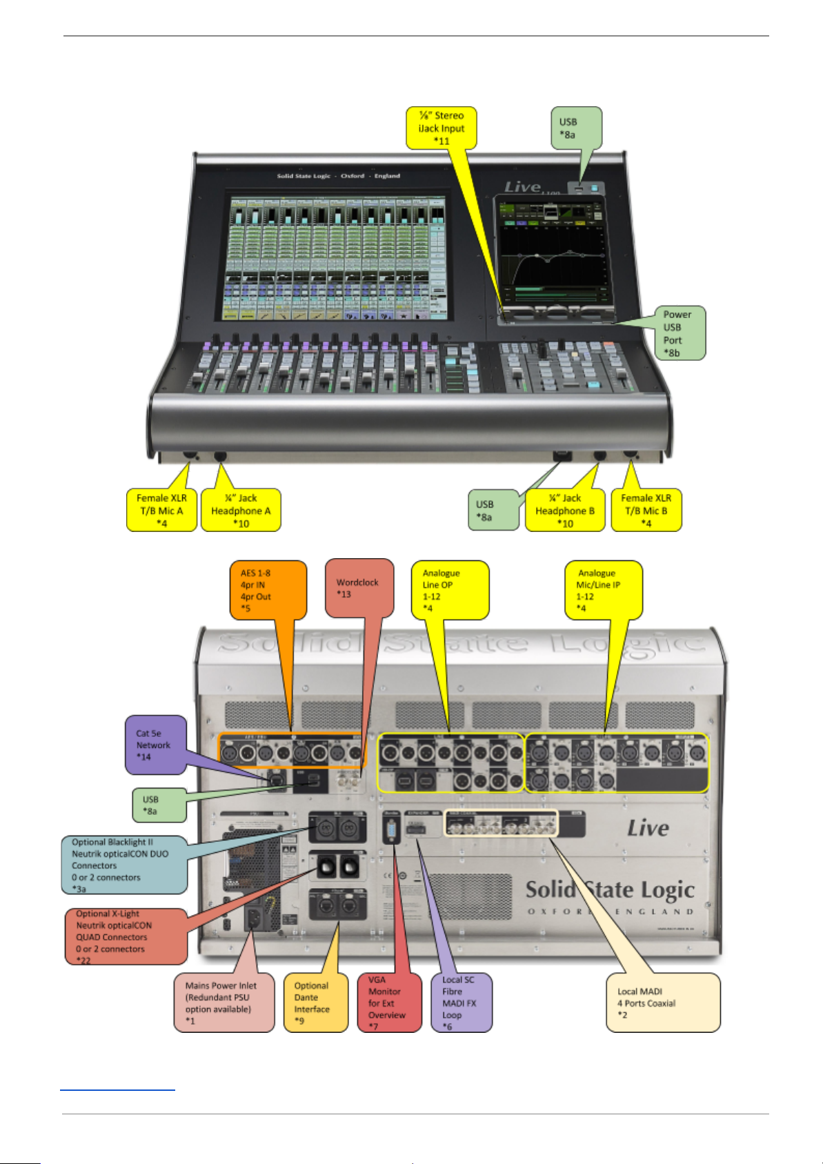
L100 Console
L100 Connections - Front
L100 Console Connections - Rear
Connections Key
www.solidstatelogic.com Page 10 of 43
Page 11
SSL Live Installation Information
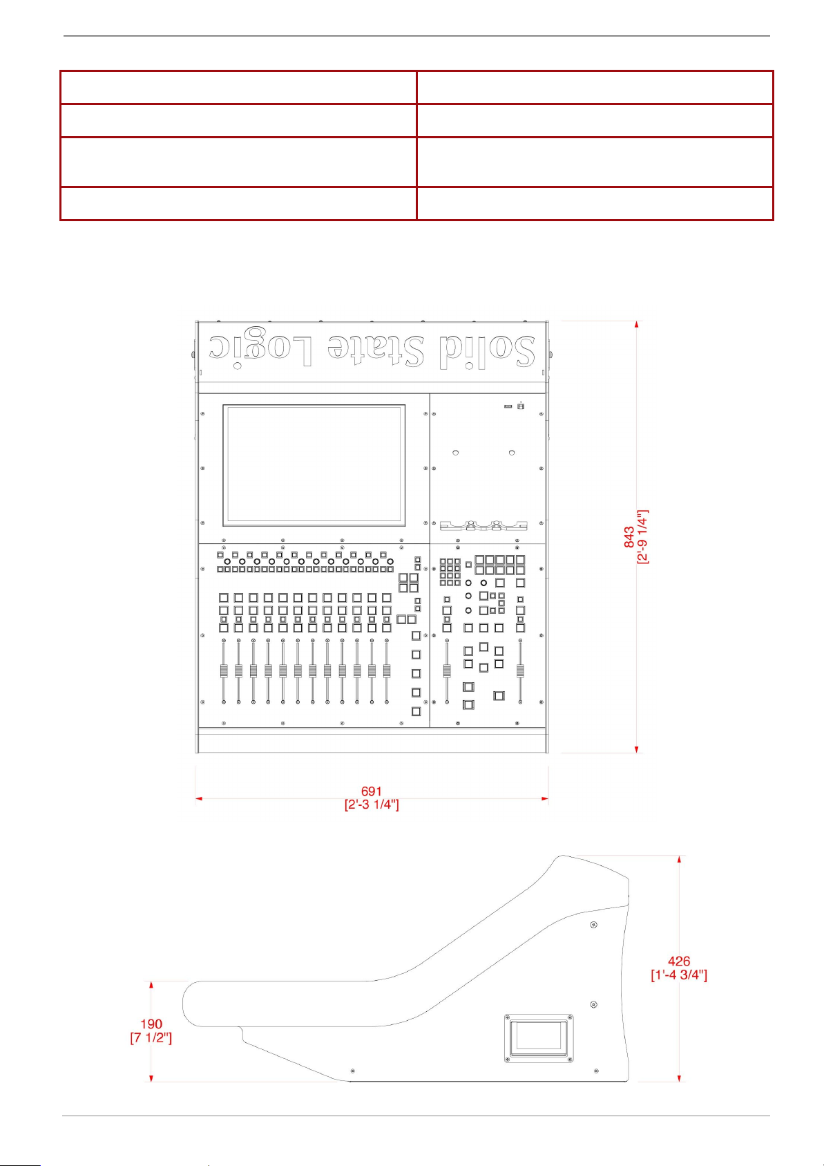
L100 Console Weight, Power & Dimensions
Weight (without flight case)
52 kg (114.7 lbs)
Weight (with flight case)
130 kg (286.6 lbs)
Acoustic Noise
With non-redundant PSU: = NR23
With redundant PSUs: = NR25
Power
<360 W
Console Dimensions: (upper figures in millimeters, lower figures, inches) - A DXF drawing is
available from SSL
Plan View
Side View
www.solidstatelogic.com Page 11 of 43
Page 12
SSL Live Installation Information
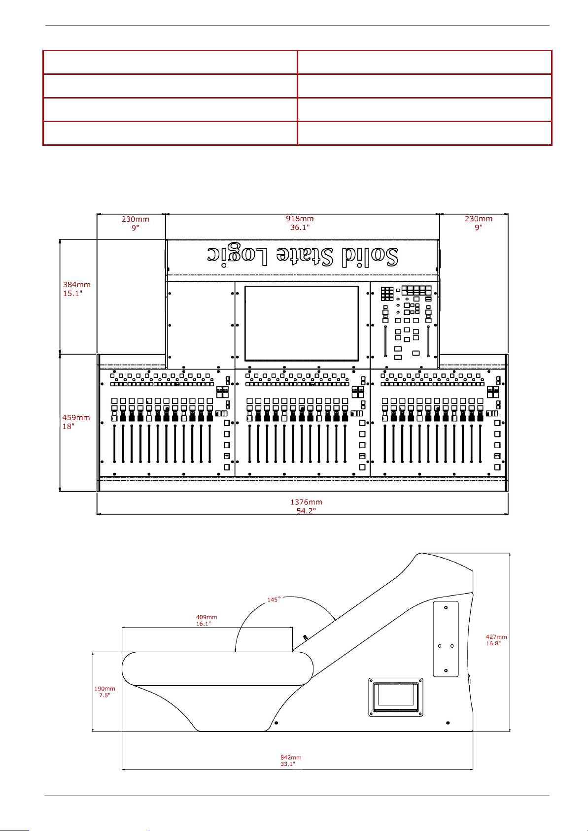
L200 Console
L200 Connections - Front
L200 Console Connections - Rear
Connections Key
www.solidstatelogic.com Page 12 of 43
Page 13
SSL Live Installation Information
L200 Console Weight, Power & Dimensions
Weight (without flight case)
85 kg (188 lbs)
Weight (with flight case)
210 kg (463 lbs)
Acoustic Noise
< NR40
Power
<460 W
Console Dimensions: (upper figures in millimeters, lower figures, inches) - A DXF drawing is
available from SSL
Plan View
Side View
www.solidstatelogic.com Page 13 of 43
Page 14

SSL Live Installation Information
L300 & L350 Consoles
L300 & L350 Connections - Front
L300 & L350 Connections - Rear
Connections Key
www.solidstatelogic.com Page 14 of 43
Page 15

SSL Live Installation Information
L300 & L350 Console Weight, Power & Dimensions
L300
L350
Weight (without flight case)
81 kg (179 lbs)
86 kg (190 lbs)
Weight (with flight case)
171 kg (377 lbs)
176 kg (388 lbs)
Acoustic Noise
< NR30
Power
<450 W
Console Dimensions: (upper figures in millimeters, lower figures feet & inches) - A DXF drawing is
available from SSL
Plan View
Side View
www.solidstatelogic.com Page 15 of 43
Page 16

SSL Live Installation Information
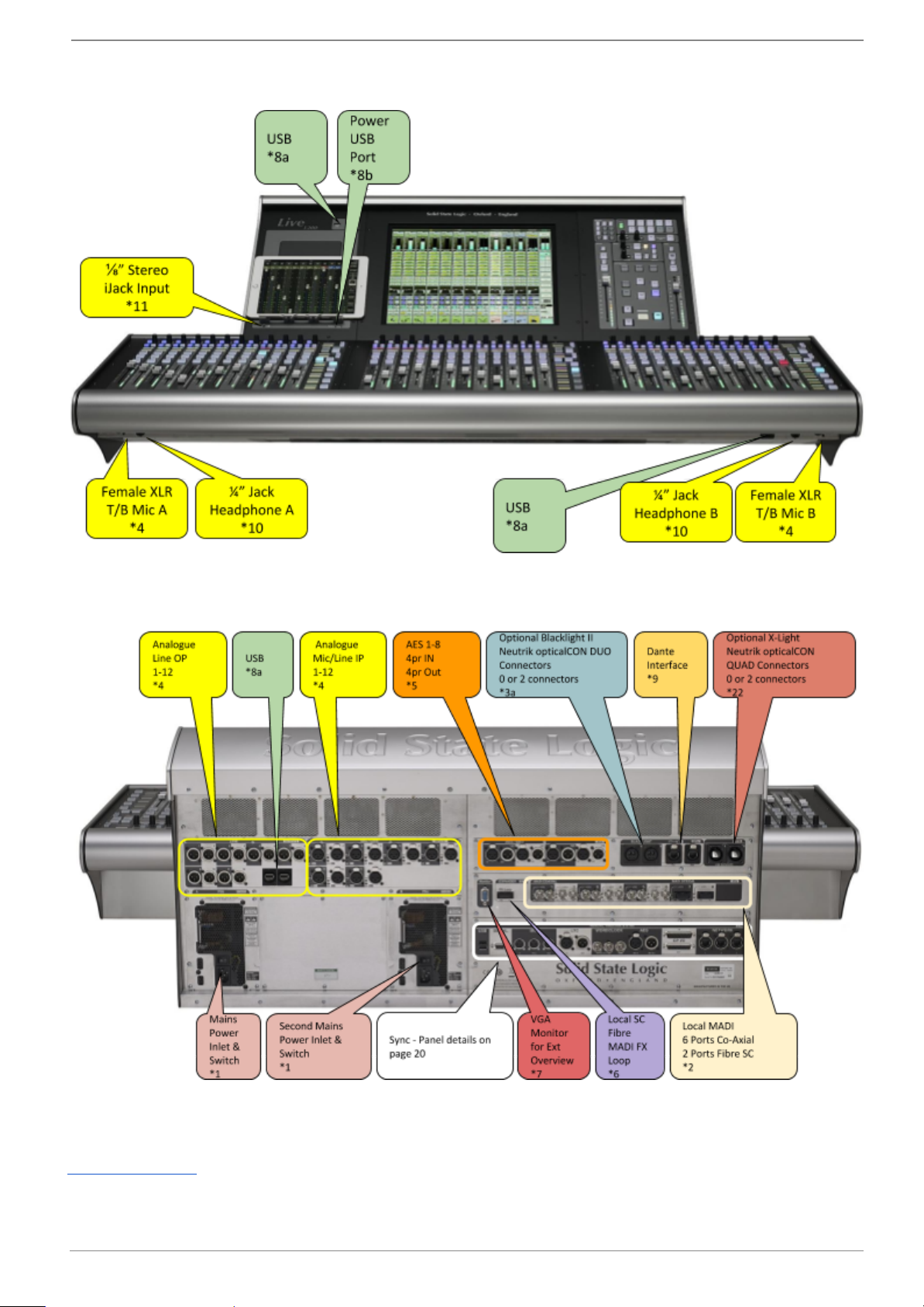
L500 Plus Console
L500 Plus Connections - Front
L500 Plus Connections - Rear
Connections Key
www.solidstatelogic.com Page 16 of 43
Page 17

SSL Live Installation Information
L500 Plus Console Weight, Power & Dimensions
Weight (without flight case)
85 kg (188 lbs)
Weight (with flight case)
190 kg (419 lbs)
Acoustic Noise
< NR40
Power
<460 W
Console Dimensions: (upper figures in millimeters, lower figures feet & inches) - A DXF drawing is
available from SSL
Plan View
Side View
www.solidstatelogic.com Page 17 of 43
Page 18

SSL Live Installation Information
L550 Console
L550 Plus Connections - Front
L550 Plus Connections - Rear
Connections Key
www.solidstatelogic.com Page 18 of 43
Page 19

SSL Live Installation Information
L550 Console Weight, Power & Dimensions
Weight (without flight case)
90 kg (198 lbs)
Weight (with flight case)
195 kg (430 lbs)
Acoustic Noise
< NR40
Power
<460 W
Console Dimensions: (upper figures in millimeters, lower figures feet & inches) - A DXF drawing is
available from SSL
Plan View
Side View
www.solidstatelogic.com Page 19 of 43
Page 20

SSL Live Installation Information
Console Remote, Timecode & Sync Panel
(L200, L300, L350, L500 Plus, L550)
www.solidstatelogic.com Page 20 of 43
Page 21

SSL Live Installation Information
Remote Tile
Rear Connections
Mains Power Inlet - *1
USB B Connection - *8c
Connects to console via USB A-B Cable (up to 5m without active repeaters)
Remote Tile Weight, Power & Dimensions
Weight (without flight case)
9.7 kg (21.4 lbs)
Weight (with flight case)
19.7 kg (43.5 lbs)
Acoustic Noise
Fan does not start until external temperatures
reach approximately 40 ºC. Above 40 ºC, NR33.
Power
<100 W
Console Dimensions: (upper figures in millimeters, lower figures feet & inches) - A DXF drawing is
available from SSL
www.solidstatelogic.com Page 21 of 43
Page 22

SSL Live Installation Information
Plan & Side View
www.solidstatelogic.com Page 22 of 43
Page 23

SSL Live Installation Information
ML 32.32 5U Mic/Line Stagebox
Front
Rear
www.solidstatelogic.com Page 23 of 43
Page 24

SSL Live Installation Information
ML I.32 5U Mic/Line Input Stagebox
Mic/Line Only version of the ML 32.32. See ML 32.32 for relevant connector details.
*Optional Mic Splits shown on rear picture.
Front
Rear
ML O.32 5U Line Output Stagebox
Output Only version of the ML 32.32. See ML 32.32 for relevant connector details.
Front
Rear
ML 32.32 Weight & Dimensions
Height
5U - 223 mm (8.75 inches)
Depth
446 mm (17.5 inches)
Width
483 mm (19 inches)
Weight
17 kg (inc optional Split Outputs)
Power
150 W
Acoustic Noise
typically NR 40
www.solidstatelogic.com Page 24 of 43
Page 25

SSL Live Installation Information
D 32.32 AES Digital 2U Stagebox
D 32.32 Weight & Dimensions
Height
2U - 89 mm (3.5 inches)
Depth
305 mm (12 inches)
Width
483 mm (19 inches)
Weight
6.2 kg
Power
60 W
www.solidstatelogic.com Page 25 of 43
Page 26

SSL Live Installation Information
BLII.D 2U Blacklight-MADI Concentrator
BLII.D Weight & Dimensions
Height
2U - 89 mm (3.5 inches)
Depth
305 mm (12 inches)
Width
483 mm (19 inches)
Weight
6.5 kg
Power
60 W
www.solidstatelogic.com Page 26 of 43
Page 27

SSL Live Installation Information
Net I/O BLII Bridge - Blacklight II to Dante Bridge
Front
Rear
PSU Status and Sync (Clock) status LEDs. For more information on LED status meanings please see
livehelp.solidstatelogic.com/Help/DanteBridges.html.
BLII Bridge Weight & Dimensions
Height
1U - 44.5 mm (1.75 inches)
Depth
340 mm (13.4 inches)
Width Including Rack Ears
483 mm (19 inches)
Weight
4.5 kg (9.9 lbs)
Power
100-240 V
<100 W
www.solidstatelogic.com Page 27 of 43
Page 28

SSL Live Installation Information
Net I/O X-Light Bridge
Front
Rear
PSU Status, Sync (Clock) and fibre status LEDs. For more information on LED status meanings please
see livehelp.solidstatelogic.com/Help/DanteBridges.html.
X-Light Bridge Weight & Dimensions
Height
1U - 44.5 mm (1.75 inches)
Depth
340 mm (13.4 inches)
Width Including Rack Ears
483 mm (19 inches)
Weight
4.8 kg (10.6 lbs)
Power
100-240 V
<100 W
www.solidstatelogic.com Page 28 of 43
Page 29

SSL Live Installation Information
Connections - Key
*1 - Mains Power Connector
Connector Type - IEC 60320 - C13
*2 - MADI
BNC Co-axial MADI connections
Co-axial MADI
BNC connections to IEC 60169-8
Cables should be at least to Belden 1694F Low Loss Serial Digital Coax standard, fitted with high
quality BNC connections.
Cables runs between Console or Blacklight-MADI Concentrators and Stageboxes up to 75 meters.
Higher quality cable/connections can support up to 100 meters.
75 m Drum of correct cable - SSL Part Number 66DR07501
Specification for Belden cable can be found here:
edesk.belden.com/products/techdata/metric/pdf/1694F.pdf
Fibre MADI
Duplex SC multimode sockets
Fibre - Multimode 50/125 µm, maximum length <1000 m (quality cables, connections and no
intermediate connections)
*3a - Blacklight II
Redundant pair(s) of fibre connections. The pair consists of primary and redundant connections.
Connector Type - Neutrik opticalCON DUO for ruggedised applications (compatible with duplex LC
fibre connections for non-rugged applications).
Fibre - Multimode 50/125 µm, maximum length <300 m (quality cables, connections and no
intermediate connections)
Pre-terminated drums available from SSL in 150m (std) and 100m (to order) lengths.
150 m BL MM Fibre cable drum SSL Part No. 66DP15003
100 m BL MM Fibre cable drum SSL Part No. 66DP10003
Fibre - Singlemode (special order) 9/125 µm, maximum length <1 km (quality cables, connections
and no intermediate connections)
Pre-terminated drums available from SSL in 150m and 300m (both to order) lengths.
150 m BL SM Fibre cable drum SSL Part No. 66DP15004
300 m BL SM Fibre cable drum SSL Part No. 66DP30004
*3b - Blacklight II LC fibre
Redundant pair(s) of LC fibre connections. The pair consists of primary and redundant connections.
Connector Type - Duplex LC fibre connections for non-rugged applications.
Fibre - Multimode 50/125 µm, maximum length <300 m (quality cables, connections and no
intermediate connections)
www.solidstatelogic.com Page 29 of 43
Page 30

SSL Live Installation Information
*4 - Analogue
Analogue Inputs and Outputs on 3 pin XLR connections.
Dimensions: Cable Dia: 19 x 60 mm (approx.) 8-12 mm (typical)
Pinout for balanced audio:
Pin 1 Screen/Ground
Pin 2 Hot (+ve)
Pin 3 Cold (-ve)
*5 - AES/EBU
AES3 Inputs and Outputs on 3 pin XLR connections. (IEC 60958 Type I)
Dimensions: Cable Dia: 19 x 60 mm (approx.) 8-12 mm (typical)
Pinout for AES3 XLR:
Pin 1 Screen/Ground
Pin 2 Hot (+ve)
Pin 3 Cold (-ve)
*6 - MADI FX Loop
Fibre MADI connection to external effects processor.
Duplex SC multimode socket
Fibre - Multimode 50/125 µm, maximum length <1000 m (quality cables, connections and no
intermediate connections)
www.solidstatelogic.com Page 30 of 43
Page 31

SSL Live Installation Information
*7 - VGA Monitor
Connection to optional Overview monitor
Three-row 15-pin D-type DE-15 connector
Native resolution : 1280 x 1024 pixels
*8a - USB Connections
USB 2.0 spec. connections for optional keyboard, mouse or storage peripherals
Up to 500 mA
*8b - Power USB Connector
USB Power connection for tablets and USB powered devices
Up to 3 A
*8c - USB B Connection
USB B Connection. Connect to console via USB A-B cable
*9 - Dante
1 pair of Dante network connections.
Connector type: 2 x RJ45 for Primary and Secondary Connections.
*10 - Headphone Outputs
A pair of front panel mounted ¼” jack sockets for Headphones.
Headphone Output Pinout :
Sleeve Screen/Ground
Ring Right
Tip Left
*11 - 3.5 mm Jack Input
3.5 mm stereo jack socket for phones or portable media players.
*12 - Reserved
*13 - Wordclock
BNC connections to IEC 60169-8
75 Ω Characteristic Impedance, unterminated internally.
Wordclock Output is active when no Input is present. Wordclock Output follows console selected
reference source for use as a local Wordclock reference.
*14 - Connectivity Network Port
Connector type: RJ45
Cat 5e 10/100/1000 bit/s Ethernet Ports, used to connect remote devices to console (not Dante).
www.solidstatelogic.com Page 31 of 43
Page 32

SSL Live Installation Information
*15a - Console MIDI Connections
5-pin DIN standard MIDI connections for In, Out & Thru connections:
midi.org/techspecs/electrispec.php
Used for MIDI Timecode (MTC) and other MIDI control triggers/commands.
*15b - Stagebox MIDI Connections
5-pin DIN standard MIDI connections for In & Out connections.
*16 - AES 11 DARS Reference
AES11 DARS Input and Output on 3 pin XLR connections. (IEC 60958 Type I)
Dimensions: Cable Dia: 19 x 60 mm (approx.) 8-12 mm (typical)
Pinout for AES3 XLR:
Pin 1 Screen/Ground
Pin 2 Hot (+ve)
Pin 3 Cold (-ve)
*17 - LTC Connectors
Linear Time Code (LTC) in and out using Balanced XLR connections.
Dimensions: Cable Dia: 19 x 60 mm (approx.) 8-12 mm (typical)
Pinout for LTC In and Out
Pin 1 Screen/Ground
Pin 2 Hot (+ve)
Pin 3 Cold (-ve)
www.solidstatelogic.com Page 32 of 43
Page 33

SSL Live Installation Information
*18 - Video Reference
BNC connectors to IEC 60169-8
75 Ω Characteristic Impedance, Analogue video (1 Vp-p, PAL, NTSC, Composite, B&B)
*19a - Stagebox GPIO Connections
Connector Type: 25-Way D-Type Female (Combined Inputs & Outputs)
Dimensions: Cable Dia: 55 x 15 mm (approx.) 8 mm (typical)
Screwlock thread: 440-UNC
6 opto-isolated GP input and 5 relay-closure outputs
GPIO Connector Pinout
GP Output - D-type Female
Pin
Description
Pin
Description
1
Input 1A
7
+12V (450mA maximum)
14
Input 1B
20
0V Chassis
2
Input 2A
8
Output 1A
15
Input 2B
21
Output 1B
3
Input 3A
9
Output 2A
16
Input 3B
22
Output 2B
4
Input 4A
10
Output 3A
17
Input 4B
23
Output 3B
5
Input 5A
11
Output 4A
18
Input 5B
24
Output 4B
6
Input 6A
12
Output 5A
19
Input 6B
25
Output 5B
13
+12V (450mA maximum)
www.solidstatelogic.com Page 33 of 43
Page 34

SSL Live Installation Information
*19b - Console GPIO Connections
Connector Type: 25-Way D-Type Male (Inputs) and Female (Outputs)
Dimensions: Cable Dia: 55 x 15 mm (approx.) 8 mm (typical)
Screwlock thread: 440-UNC
12 opto-isolated GP input and 12 relay-closure outputs
GPIO Connector Pinout
GP Input - D-type Male
Pin
Description
Pin
Description
1
Input 1A
7
Input 7A
14
Input 1B
20
Input 7B
2
Input 2A
8
Input 8A
15
Input 2B
21
Input 8B
3
Input 3A
9
Input 9A
16
Input 3B
22
Input 9B
4
Input 4A
10
Input 10A
17
Input 4B
23
Input 10B
5
Input 5A
11
Input 11A
18
Input 5B
24
Input 11B
6
Input 6A
12
Input 12A
19
Input 6B
25
Input 12B
13
0V
www.solidstatelogic.com Page 34 of 43
Page 35

SSL Live Installation Information
GP Output - D-type Female
Pin
Description
Pin
Description
1
Output 1A
7
Output 7A
14
Output 1B
20
Output 7B
2
Output 2A
8
Output 8A
15
Output 2B
21
Output 8B
3
Output 3A
9
Output 9A
16
Output 3B
22
Output 9B
4
Output 4A
10
Output 10A
17
Output 4B
23
Output 10B
5
Output 5A
11
Output 11A
18
Output 5B
24
Output 11B
6
Output 6A
12
Output 12A
19
Output 6B
25
Output 12B
13
+12V (450mA max)
*20 - Setup Controls: MADI
REMOTE - Padlock LED
Red indicates SETUP controls are locked
Press and hold RATE & CLOCK simultaneously to activate controls. The Padlock LED will flash green
to indicate controls are unlocked. After a few moments of inactivity, the controls will lock again.
REMOTE - On LED
On LED flashes green when remote MADI control data is received.
RATE - Sample Rate
RATE button selects different box sample rates (See Live Console Synchronisation & Clocking earlier
in this guide)
www.solidstatelogic.com Page 35 of 43
Page 36

SSL Live Installation Information
ID - Daisy Chaining Stageboxes
Sets Unit ID if stageboxes are daisy chained (See Live Console Synchronisation & Clocking earlier in
this guide)
CLOCK
The CLOCK button selects unit clock reference to MADI, Wordclock or internal inputs.
MADI LED colour meanings are as follows:
Green - Main and Redundant are both locked
Flashing Red and Green - Only one MADI receiver is locked
Red - Neither Main or Redundant are locked
Off - Stagebox is clocking from its internal clock source
*21 - Dante SFP Cages
1 pair of Dante network connections.
SFP cages, can be fitted with RJ45 SFPs or singlemode/multimode fibre.
*22 - X-Light fibre
Redundant pair(s) of fibre connections. The pair consists of primary and redundant connections.
Connector Type - Neutrik opticalCON QUAD for ruggedised applications.
Fibre - Multimode 50/125 µm, maximum length <300 m (quality cables, connections and no
intermediate connections)
Pre-terminated drums available from SSL in 150 m (std) and 100 m (to order) lengths.
150 m X-Light MM Fibre cable drum SSL Part No. 66DPX1501
100 m X-Light MM Fibre cable drum SSL Part No. 66DPX1001
www.solidstatelogic.com Page 36 of 43
Page 37

SSL Live Installation Information
Typical Installation Diagrams
Simple Single System
L500 Plus Control Surface shown with optional local IO and additional Co-ax MADI interface provide
32 analogue IO and 16 AES IO at FOH position. 12 MADI ports plus MADI FX Loop.
2 off ML 32.32 stageboxes provide 64 Mic/Line inputs and 64 line outputs on stage
Additional/different MADI stageboxes can be connected as required.
www.solidstatelogic.com Page 37 of 43
Page 38

SSL Live Installation Information
Blacklight II Single System (with Redundancy)
L500 Plus Control Surface shown with optional local IO, additional Co-ax MADI interface and optional
4 port BL II Blacklight interface to provide 32 analogue IO and 16 AES IO at FOH position. 12 MADI
ports plus MADI FX Loop.
2 pairs of Blacklight II connections provide 2 x 256 channels to/from stage using fibre up to <300m
(quality cables, connections and no intermediate connections).
1 off BLII.D Blacklight II MADI concentrator provides 4 redundant on-stage MADI ports connected
to...
3 off additional I.32 stageboxes provide an additional 96 Mic/Line inputs
1 off additional D 32.32 AES boxes provide 32 AES digital IO
Co-axial MADI connected IO
1 off ML 32.32 stageboxes provide 32 Mic/Line inputs and 32 line outputs on stage
1 off additional D 32.32 AES boxes provide 32 AES digital IO
Total IO of 128 Mic/Line Inputs, 32 Line Outputs, 64 AES IO, 36 GP inputs, 30 GP Outputs
www.solidstatelogic.com Page 38 of 43
Page 39

SSL Live Installation Information
Dual Console MADI System
Two L500 Plus Control Surfaces (FOH and Monitors) shown with optional local IO and additional Co-ax
MADI interface to provide 32 analogue IO and 16 AES IO at the consoles, 12 MADI ports plus MADI FX
Loop.
FOH Console has redundant MADI RX/TX to MADI ports 1 & 2 of the ML I.32 stageboxes. Monitor
Console is connected to the TX only connection from MADI ports 3 & 4. FOH console controls the Mic
Amp Gain, Monitor console uses Gain Sharing to adjust local levels.
3 off additional I.32 stageboxes provide an additional 96 Mic/Line inputs
1 off additional D 32.32 AES boxes provide 32 AES digital IO
1 off ML O.32 stageboxes provide 32 line outputs on stage from Monitor console
Total IO of 96 Mic/Line Inputs, 32 Line Outputs, 32 AES IO, 30 GP inputs, 25 GP Outputs
www.solidstatelogic.com Page 39 of 43
Page 40

SSL Live Installation Information
Dual Console System with Blacklight from each console
Two L500 Plus Control Surfaces (FOH and Monitors) shown with optional local IO, additional Co-ax
MADI interface and optional 4 port BL II Blacklight interface to provide 32 analogue IO and 16 AES IO
at the consoles, 12 MADI ports plus MADI FX Loop.
2 pairs of Blacklight II connections provide 2 x 256 channels to/from stage using fibre up to <300m
(quality cables, connections and no intermediate connections).
FOH Console has redundant Blacklight II Fibre connections to A port of the BL II.D Blacklight MADI
Concentrator.
Monitor Console redundant Blacklight II Fibre connections to B port of the BL II.D Blacklight MADI
Concentrator.
FOH console controls the Mic Amp Gain, Monitor console uses Gain Sharing to adjust local levels.
1 off BLII.D Blacklight II MADI concentrator provides 4 redundant on-stage MADI ports connected
to...
3 off additional I.32 stageboxes provide an additional 96 Mic/Line inputs
1 off additional D 32.32 AES boxes provide 32 AES digital IO
Co-axial MADI connected IO
1 off ML O.32 stagebox provides 32 line outputs on stage from Monitor console
Total IO of 96 Mic/Line Inputs, 32 Line Outputs, 32 AES IO, 36 GP inputs, 30 GP Outputs
www.solidstatelogic.com Page 40 of 43
Page 41

SSL Live Installation Information
Optional Console Stand
Console Dimensions with optional stand: (figures in millimeters)
L500 / L500 Plus / L550 (SSL part 62A7000XL)
www.solidstatelogic.com Page 41 of 43
Page 42

SSL Live Installation Information
L300 / L350 (SSL part 62A7300XL)
www.solidstatelogic.com Page 42 of 43
Page 43

SSL Live Installation Information
Visit SSL at: www.solidstatelogic.com
© Solid State Logic
All Rights reserved under International and Pan-American Copyright Conventions
SSL and Solid State Logic are ® registered trademarks of Solid State Logic
Live L200™, Live L300™, Live L350™, Live L500™, L500 Plus™, Live L550™, Blacklight™, X-Light™,
ML32:32™ are ™ trademarks of Solid State Logic
Dante™ and Audinate™ are trademarks of Audinate Pty Ltd
All other product names and trademarks are the property of their respective owners and are hereby
acknowledged
No part of this publication may be reproduced in any form or by any means, whether mechanical or
electronic, without the written permission of Solid State Logic, Oxford, OX5 1RU, England
As research and development is a continual process, Solid State Logic reserves the right to change
the features and specifications described herein without notice or obligation.
Solid State Logic cannot be held responsible for any loss or damage arising directly or indirectly from
any error or omission in this manual.
PLEASE READ ALL INSTRUCTIONS, PAY SPECIAL HEED TO SAFETY WARNINGS.
E&OE
January 2019
www.solidstatelogic.com Page 43 of 43
 Loading...