

Soleus Air SG-PTAC-09HPDA, SG-PTAC-12HPDA, SG-PTAC-15HPDA Owner's Manual
9,000---15,000 BTU/HR
Thank you for choosing Soleus air conditioner.
SOLEUS AIR CONDITIONERS
SG-PTAC-15HPDA
SG-PTAC-12HPDA
SG-PTAC-09HPDA
OWNER'S MANUAL
Packaged Terminal
Air Conditioner
before operating the unit and keep
it for consultation.
For correct operation, please read this owner's manual carefully
Packaged Terminal Air Conditioner/Heat Pump
Model
......
■ ........................
■ ................................
■
..............................
■ ........................
■ ........................
■
............................
■
....................
■
.............................
■
................. ...........
■ .........................
■ .................................
Do not dispose this product as unsorted municipal waste.
Collection of such waste separately for special treatment
is necessary.
CONTENTS
This symbol stands for the items
should be forbidden
This symbol stands for the items
should be followed
The figures in this manual may be different with the material objects, please refer
to the material objects for reference.
SYSTEM CONFIGURATION
HOW TO CONNECT
SAFETY CONSIDERATIONS
GENERAL INFORMATION
UNIT FEATURES
ELECTRICAL DATA
INSTALLATION
OPERATION
CARE AND CLEANING
PREVENTATIVE MAINTENANCE
TROUBLESHOOTING
........
LIMITED WARRANTY
■
.............................
1
1
4
2
5
10
11
14
15
16
17
18
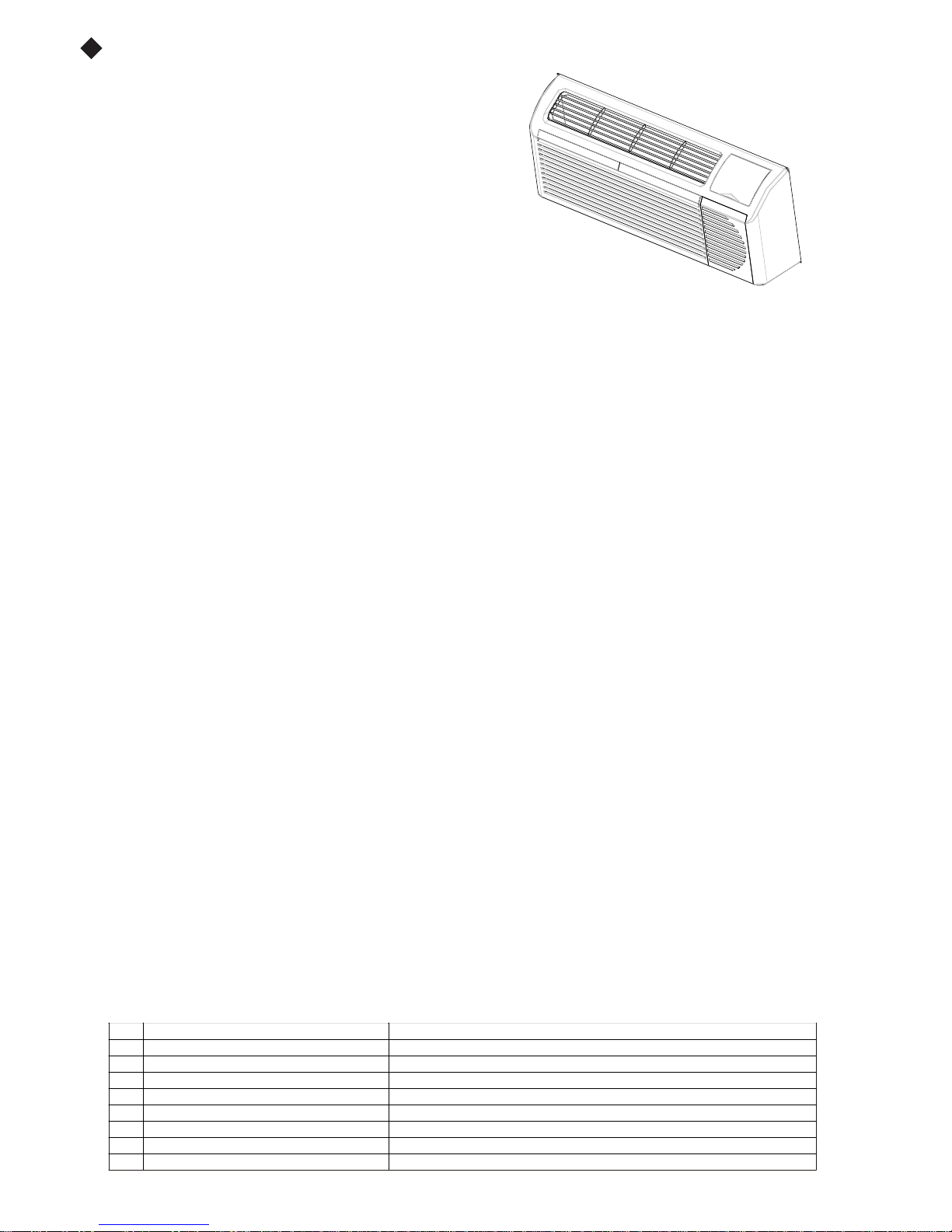
UNIT FEATURES
This Premium unit has many exciting features which
are different than those found on standard PTAC
models. The owner must be familiar with these
featuresin order to fully understandthe operationand
capability of the unit.
• Intelligence – Your Premium unit has an on board
computerthatutilizesrealtimediagnosticstoprolong
the life of your unit. There is an LED indicator on the
control board, behind the front panel, that will flash
an error code if the unit has detected some kind of
fault condition. In many cases, the unit will
automatically clear the fault condition and continue
operating with no interruption. In some cases, the
condition cannot be cleared and the unit will require
displayed on the digital display. For a detailed list of
Status LED Indicator Definitions for further details.
• Memory – Your Premium unit also has memory. If power is lost, all of the control settings (setpoint,
mode, fan speed, on/off and configuration) are
start back up in the m ode (and configuration) it was
• Premium Sound
optimum sound, the indoor fan will always run a
help reduce any compressor starting noise.
• Random Compressor restart -- To help prevent
your PTACs starting at the same time), the
restart delay feature. Wheneverthe unit is plugged in,
restart wil l occur.
Compressor Protection -- To prevent short cycling
•
random start--up delay
• Au tomati c room freeze protection – automatically
too cold, where water pip es might freeze. If the unit
active(which is the default condition), then whenever
temperature b elo w 4 0°F, the fan motor and el ect ri c
If F reeze protect i on is not required , change the
section on unit configuration).
Automatic defrost protection (fo r heat pump
•
too cold (approx. 35°F) and the unit can no longer
automaticallyswitchto electric heating. Theunit will
temperature rises enough (approx. 40°F), so the
• Automati c Q u ick Warm--u p (for heat p u mp
below the set point temp erat ure, th e reverse cycle
for one cycle, until h eat i ng is satis fi ed.
LED Indicator’s and Buttons -- The touch pad has
•
SETPOINT UP and SETPOINT DOWN. It al so has
setpoint operation, to indicate the unit’s status. The
HEAT, indicate what operating mode is active. The
indicate the fan s p eed that is selected. Th e LED
status LED. If the unit is in ON mode, the LED will
• Configure Fan to Optimize Selected Application
configuring the fan to run in continuous mode or
heater (can be different for b ot h heat i n g an d coo l in g
compressor or electri c heater st op s in ord er b l ow off
1 Indoor air temp sensor open/short 7--- segment display ‘F1’, with STATUS light flash 1 time,off 2 seconds
2 Indoor coil sensor open/short 7--- segment display ‘F2’, with STATUS light flash 2 time,off 2 seconds
3 Outdoor coil sensor open/short 7--- segment display ‘F4’, with STATUS light flash 4 time,off 2 seconds
4 Freeze Guard protection 7--- segment display ‘FP’
5 Thermostat wiring error STATUS light flash 9 times and off 3 sec, repeat
6 Indoor coil high temp protection STATUS light flash 8 times and off 3 sec, repeat
7 Defrost (heat pump type) STATUS light flash 7 times and off 3 sec, repeat
8 Outdoor coil high temp protection STATUS light flash 6 times and off 3 sec, repeat
9 Indoor coil freeze protection STATUS light flash 5 times and off 3 sec, repeat
NOTE: When status light is flashing, it will be ON for 0.5 seconds and OFF for another 0.5 seconds.
–
The unit n ot only does it
of 3 minutes on the
service. In th os e cases, an “F x ” fai l ure mo de wi l l be
all error codes and “Fx” conditions, see Table 6 --
remembered. So when power is restored, the unit will
in, when power was l ost.
have2
fan m otors and a tangential blower wheel for
minimum of 10 seconds before the compressor, to
power surges aft er a power outage (from many of
compressor is equipped with a 2:45 to 3:15 random
or power has been restarted, a random compressor
of the compressor and maximize it’s life, there is a
compressor and a minimum compressor run time of 3
will keep the temperature in the room from getting
is configured for the freeze protecti o n feature t o be
power is supplied to the unit, if the unit senses
heater are turned on and will warm the room to 50_F.
configuration switch to turn the feature off (see
models only) – When the outdoor temperature gets
effectively heat with the compressor, the unit will
then heat wit h el ect ri c heat until t h e ou ts i d e
compresso r can be used again .
models only) -- If the room temperature falls to 5°F
heat is shut off and the electric strip heat is turned on
buttons for MODE, FANSPEED, ON/OFF,
LEDs t hat correspond to the mode, fan speed and
LEDs below the mode button, FAN, COOL, and
LEDs below the Fan button, Low, Med and Hi,
located in t he l ower ri gh t co rner i s t he un i t O n/ Off
be green. If the unit is OFF, the LED will be red.
-- Unit can be optimized to selected application by
cycle on and off with the compressor and electric
modes). In cycle mode, fan will continue to run after
any residual heat or cool left on coil.
Table 6—STATUS LED Indicator Definitions
2
Fig. 2
minutes.

UNIT FEATURES CONTINUED
• Unit Configuration – There are many different
and the digital keypad, that allow you to configure
unit configuration for moredetails. Following are the
mentioned:
• _For_C – The unit can display in either _For_C
• Indoor Temperature Sensor Biasing – Optimize
application(one for cooling andanother for heating)..
• Emergency Hea t (for Heat Pu mp Only) – Disable
only wit h Electric Heat).
• Dis p l ay Setp oi n t OR Room Temperature -- T h e
temperature OR setpoint only, during heating and
more details.
• Limit the Setpoint Range -- The unit can be
display will always show thecompletesetpointrange,
configuredminimum andmaximum setpointselected.
• Energy Management – S ometimes known as
unit can be manually disabled from a different
automatically turn itself off. If no voltage is detected
configurationpossibilities, through both dipswitches
the unit for your exact application. See section on
configuration selections that havenotpreviously been
the room temperature sensor reading to your exact
the compressor during heating mode operation (heat
unit can be configured to display the room
cooling modes. S ee section on unit configuration for
configuredtolimit the controlling setpoint range. The
but the controlling setpoint will be limited to t he
See section on unit configuration for more details.
Front Desk Control, an input is provided so that the
location. If the unit detects 24vac on this input, it will
on the input, the unit will run normally.
3
ELECTRICAL DATA
!
ELECTRICAL SHOCK HAZARD
Failure to follow this warning could result in personal
DO NOT alter cord or plug or use an extension cord.
POWER CONNECTION OPTIONS
Appropriate power co rd accessory ki t is det ermi n ed
The un i t does not come with a power co rd (or
be ordered to connect the unit to the outlet. If the
must be ordered.
IMPORTANT: For 265V units, if power cord
long and must plug into the accessory electrical
Be sure that your outlet matches the appropriate blade
the service co rd.
All wiring , including installati on o f the recep t acl e,
ordinances and regulations. National codes require
device on all 208/230V power cords. Be sure to select
ALL UNITS
Wire Size
Use recommended wire size given in Table 1 and
with local and national codes. All units are
NOTE: Use copper conductors only.
Table 1—SUGGESTED BRANCH CIRCUIT WIRE SIZES*
NAMEPLATE AMPS AWG WIRE SIZE{
7.0 to 12 14
12.1 to 16
16.1 to 24 10
Grounding
For safety and protection, the unit is grounded
wire provided on hard wired units. Be sure
VOLTAGE SUPPLY
Check voltage supply at outlet. For satisfactory
ranges found on the data information plate.
Cord--connected Units
The 250--v field supplied outlet must match the plug
of the service co rd. The s t and ard cord--conn ect ed
for operatio n. Refer to Table 2 for pr op er recept acl e
Power Cord
The power cord for 230/208v units provide power
disconnects when unsafe conditions are detected.
buttononplughead.
Upon completion of unit installation for 230/208V
using the TEST/RESET buttons on the plug head.
NOTE: The 265v models do not incorporate this
Protection
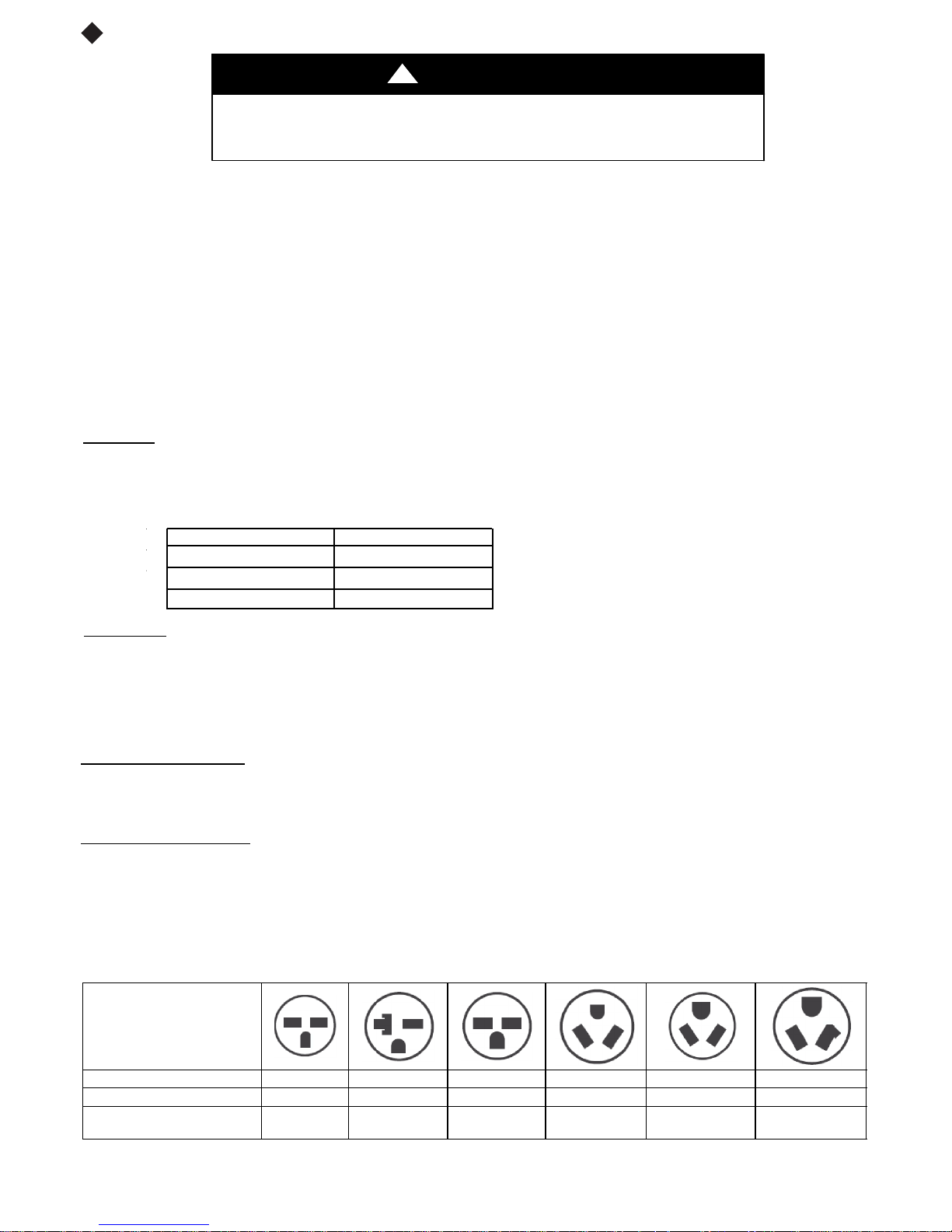
Table 2—RECEPTACLES AND FUSE TYPES -- 250, 265 VOLTS
design ed to operate off ONE s i n gl e bran ch circuits
12
through the service cord plug or through separate
that the branch circuit or general purpose outlet is
feature as t hey require use of the electrical subbase
WARNING
injury or death and/or property damage
by the voltage, and amperage of the branch circuit.
hard wire kit). An accessory po wer cord ki t must
unit is to be hard wired, an accessory hard wire kit
accessory option is selected, the cord is only 18”
265V subbase.
configurat i o n of th e plug and t hat i t is with i n reach of
must b e i n accordance wit h the NEC and l o cal codes,
the use of an arc faul t or leakage current detecti o n
the correct cord for your installation.
install a singlebranch circuit. All wiring must
LEGEND
AW G --- A m e r ic a n W i r e G a u ge
* Single circuit from main box.
{ Based on copper wire at 60_C temperature rating.
results, the voltage range must always be within the
for the s tandard 208/230--v units and be within reach
265--v units require an acces so ry el ect ri cal subbase
and fuse type.
cord fi re protection.
Unit power automatically
Power t o the unit can be restored by pressing the reset
models, an operational check should be performed
comply
only.
grounded.
ground
accessory.
RECEPTACLE
AMPS 15 20 30 15 20 30
RATED VOLTS 250 250 250 265 265 265
T I M E --- D E L A Y T Y P E F U S E
(or HACR Circuit Breaker)
LEGEND
HACR --- Heating, Air Conditioning, Refrigeration
* May be used fro 15 --- amp applications
15 20* 30 15 20 30
4
 Loading...