

Page 1
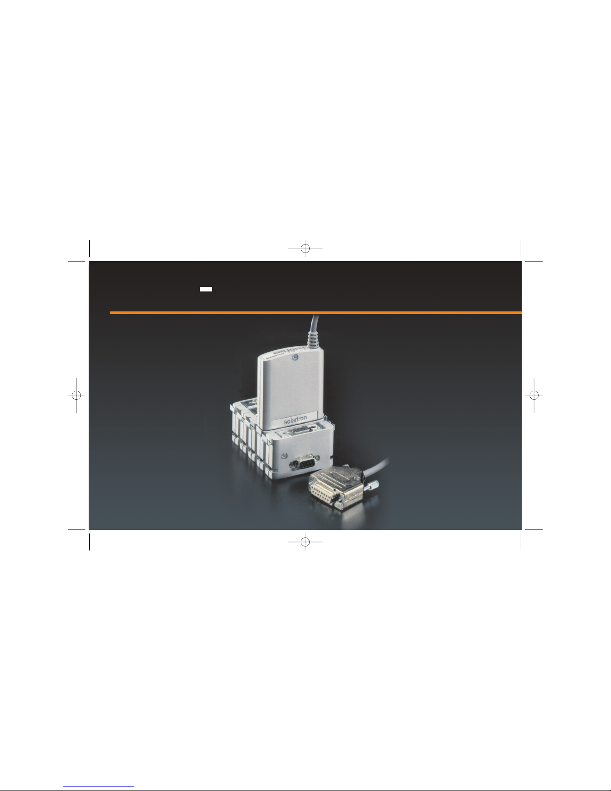
Digital Input/
Output Module
solar
tron
Manual No. 502237
Issue 2
DIOM 502237_Issue 2.qxd 20/07/2005 15:38 Page fcov1
Page 2

Part No. 502237 Issue 2
Information in this document is subject to change without notice. Companies, names and data used
in examples herein are fictitious unless noted otherwise. No part of this document may be
reproduced or transmitted in any form or by means, electronic or mechanical, for any
purpose, without the express permission of Solartron Metrology.
© 2000 Solartron Group Ltd. All rights reserved.
Orbit is a trademark of Solartron Group Ltd
All other brand names, product names or trademarks belong to their respective holders.
DIOM 502237_Issue 2.qxd 20/07/2005 15:38 Page fcov2
Page 3

1.0 Introduction
INTRODUCTION . . . . . . . . . . . . . . . . . . . . . . . . . .3
THIS MANUAL . . . . . . . . . . . . . . . . . . . . . . . . . . . .3
SAFETY SUMMARY . . . . . . . . . . . . . . . . . . . . . . .4
WARNINGS: . . . . . . . . . . . . . . . . . . . . . . . . . . . . .4
2.0 Detail Specification
DIOM GENERAL SPECIFICATION . . . . . . . . . . . .5
EMC Compliance . . . . . . . . . . . . . . . . . . . . . . .6
IP Rating . . . . . . . . . . . . . . . . . . . . . . . . . . . . . .6
PIN CONNECTIONS . . . . . . . . . . . . . . . . . . . . . . .7
I/O Port: Input Specification . . . . . . . . . . . . . . .9
I/O Port: Output Specification - Driver
Configuration External Supply . . . . . . . . . . . . .10
0 V connections: Pins 9 to 12 DIOM
connector . . . . . . . . . . . . . . . . . . . . . . . . . . . . .11
I/O Port: Output Specification - Driver
Configuration Using Orbit Supply . . . . . . . . . .12
I/O Port: Output Specification - Logic
Configuration . . . . . . . . . . . . . . . . . . . . . . . . . .13
3.0 Communication with the DIOM
ORBIT COMMANDS . . . . . . . . . . . . . . . . . . . . . . .14
4.0 Application - Hardware
CONNECTING TO THE DIOM. . . . . . . . . . . . . . .20
EMC IMMUNITY ENHANCEMENT
SUGGESTIONS . . . . . . . . . . . . . . . . . . . . . . . . . .21
5.0 Application - Software
INPUT / OUTPUT CONTROL . . . . . . . . . . . . . . . .22
MULTIPLE READINGS . . . . . . . . . . . . . . . . . . . . .24
Return of Goods
Index
1
Manual No. 502237 Issue 2
Index
DIOM 502237_Issue 2.qxd 20/07/2005 15:38 Page 1
Page 4
Introduction
The Digital Input / Output Module (DIOM) enables the
'Orbit Network' to interface with the outside world. The
module provides 8 general-purpose input / output lines,
housed in the standard Orbit Module case. Each line
can be individually configured to Input or Output.
Input / Output line are connected via a 0.5-meter flying
lead and a 15-way D-type connector.
This Manual
The manual describes the technical specification of the
product enabling you to connect to the DIOM. All
communication with the DIOM, including configuration
of the unit, is carried out using the 'Orbit Command'
language, which is described in detail in this manual.
1.0: Introduction
1.0: Introduction
2
Manual No. 502237 Issue 2
DIOM 502237_Issue 2.qxd 20/07/2005 15:38 Page 2
Page 5
Safety Summary
WARNING statements identify conditions or practices
that could result in personal injury or loss of life.
CAUTION statements identify conditions or practices
that could result in damage to the equipment or other
property.
Symbols in this document:-
This symbol indicates where applicable
cautionary or other information is to be found.
WARNINGS:
Do not operate in an explosive atmosphere
To avoid explosion, do not operate this equipment in an
explosive atmosphere.
This equipment is not intended for use in safety critical
applications.
Do not exceed rated voltages
This equipment is designed to interface to a maximum
of 30 V dc.
1.0: Introduction
1.0: Introduction
3
Manual No. 502237 Issue 2
DIOM 502237_Issue 2.qxd 20/07/2005 15:38 Page 3
Page 6
CAUTION:
Failure to observe the limits in this specification
could result in damage to this equipment and
any equipment connected to it.
NOTES:
This equipment contains no user serviceable parts.
This equipment must be returned to a Solartron Dealer
for all service and repair.
Low Voltage
This equipment operates at below the SELV and is
therefore outside the scope of the Low Voltage
Directive.
DIOM General Specification
Module Temperature:
-20°C to + 70°C (-4°F to 158°F)
except where specified.
Module Supply (from Orbit Network):
4.75 V - 5.25V @ 60 mA max. (all outputs on)
Does not include current sourced from +5V Orbit
supply (pin 13).
CAUTION:
This is the supply for the Module only. An
external supply is required for driving loads.
1.0: Introduction
1.0: Introduction
4
Manual No. 502237 Issue 2
DIOM 502237_Issue 2.qxd 20/07/2005 15:38 Page 4
Page 7

EMC Compliance
BS EN 50081-1: 1992 Generic emission standard Part 1.
Residential, commercial and light Industry.
BS EN 50081-2: 1995 Generic immunity standard Part 2.
Industry environment.
The above compliance statements is for representative
system. Layout of cables, supply sources and electrical
environment may affect performance.
IP Rating
IP53 when mounted in an upright position.
IP50 when mounted in any position (other than
upright.).
1.0: Introduction
1.0: Introduction
5
Manual No. 502237 Issue 2
DIOM 502237_Issue 2.qxd 20/07/2005 15:38 Page 5
Page 8
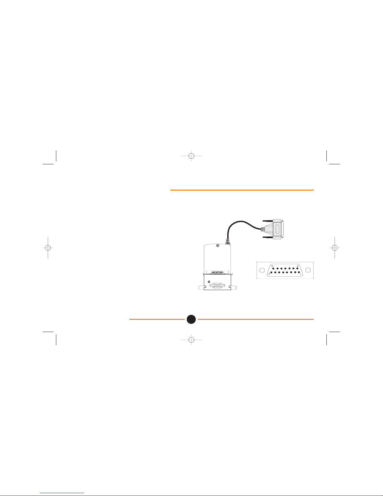
Pin Connections
Inputs / Outputs:
8 lines used as either input or outputs, connected via a
short (0.5 m) flying lead and 15-way D-type connector.
Pin Number Pin Label Pin Number Pin Label
pin 1 I/O bit 0 pin 8 I/O bit 7
pin 2 I/O bit 1 pin 9 0 V
pin 3 I/O bit 2 pin 10 0 V
pin 4 I/O bit 3 pin 11 0 V
pin 5 I/O bit 4 pin 12 0 V
pin 6 I/O bit 5 pin 13 +5 V
pin 7 I/O bit 6 pin 14 & 15 NC
DIOM 15-way D-type pin connections
2.0: Detail Specification
2.0: Detail Specification
6
Manual No. 502237 Issue 2
DIOM 502237_Issue 2.qxd 20/07/2005 15:38 Page 6
Page 9

I/O Port: Input Specification
• 4K7 pull up to Orbit +5 V
• High-level input voltage ≥ +3.15 V
• Low-level input voltage ≤ +1.35 V
Absolute Maximum Ratings
V
IH(MAX)
+30 V
V
IL(MIN)
-0.5 V
I
IL
≤ 1mA (source)
Note: Output driver MUST be set high (logic 1) using
the OrbitPreset command before using the port
as an input.
2.0: Detail Specification
2.0: Detail Specification
7
Manual No. 502237 Issue 2
DIOM 502237_Issue 2.qxd 20/07/2005 15:38 Page 7
Page 10

I/O Port: Output Specification - Driver
Configuration External Supply
Typical specification, assuming 8 outputs used at 100%
duty cycle.
• Open drain
• Low-level output voltage ≤ +0.2 V
Absolute Maximum Ratings - Each Output
V
OH(MAX)
+30 V
V
OL(MIN)
-0.5 V
I
OL
≤ 50 mA (sink)
2.0: Detail Specification
2.0: Detail Specification
8
Manual No. 502237 Issue 2
DIOM 502237_Issue 2.qxd 20/07/2005 15:38 Page 8
Page 11

0 V connections: Pins 9 to 12 DIOM
connector
Return current for load connected to an external
supply must be connected to a local 0V (Load
0V). This prevents the load 0V current returning
through pins 9 - 12. on to the orbit network.
• Maximum difference between Orbit 0 V and
Load 0 V < 0.5 V.
2.0: Detail Specification
2.0: Detail Specification
9
Manual No. 502237 Issue 2
DIOM 502237_Issue 2.qxd 20/07/2005 15:38 Page 9
Page 12

I/O Port: Output Specification - Driver
Configuration Using Orbit Supply
+5 V Orbit Supply (pin 13 DIOM connector):
Maximum 50mA total current is available from
the Orbit supply via the DIOM. This can be used
for external loads such as active switches,
indicators and sensing devices.
• Open drain
• Low-level output voltage ≤ +0.2 V
Absolute Maximum -Total
I
Orbit(MAX)
≤ 50mA (source total)
2.0: Detail Specification
2.0: Detail Specification
10
Manual No. 502237 Issue 2
DIOM 502237_Issue 2.qxd 20/07/2005 15:38 Page 10
Page 13

I/O Port: Output Specification - Logic
Configuration
(for driving typical 5V logic inputs).
• High-level voltage VH - 4K7 internal pull up to Orbit +5 V
• Low - level voltage VL ≤ +0.2 V (50mA max sink)
2.0: Detail Specification
2.0: Detail Specification
11
Manual No. 502237 Issue 2
DIOM 502237_Issue 2.qxd 20/07/2005 15:38 Page 11
Page 14

Orbit Commands
The following Orbit commands allow you to communicate with the DIOM. (Also refer to the Orbit Network Measurement
System manual). When using the RS232 Interface Module please refer to the RS232 Interface Module manual.
Orbit Command OrbitRst
Description: reset all Orbit Modules.
Type: broadcast
Parameters: card, channel
Will reset ALL the Orbit Modules on a network at the same time. To set the Orbit Modules to the required Baud rate this
command MUST be sent after the network is powered up and before any other command. Allow at least 0.5 second for
completion of the command.
3.0: Communication with the DIOM
3.0 Communication with the DIOM
12
Manual No. 502237 Issue 2
DIOM 502237_Issue 2.qxd 20/07/2005 15:38 Page 12
Page 15

Orbit Command OrbitSetaddr
Description: set Orbit Module address.
Type: addressed
Parameters: card, channel, address, identity, option
Each Orbit Module is given a unique 10 byte identity (ID) during manufacture. When used on a network it is more
efficient to use a shorter temporary ADDRESS stored in the Orbit Module memory; this is a number between 1 and 31.
This command is used to set the temporary address.
3.0: Communication with the DIOM
3.0 Communication with the DIOM
13
Manual No. 502237 Issue 2
DIOM 502237_Issue 2.qxd 20/07/2005 15:38 Page 13
Page 16

Orbit Command OrbitRead1
Description: returns the state of the DIOM inputs.
Type: addressed
Parameters: card, channel, address, reading
The 8 least significant bits of the returned 16-bit number show the state of the input pins. Each pin must first be set
high (via OrbitPreset) if it is to be used as an input. A low state on the input pin will be returned as a logic low (0), a
high state on the input pin will be returned as a logic high (1).
3.0: Communication with the DIOM
3.0 Communication with the DIOM
14
Manual No. 502237 Issue 2
DIOM 502237_Issue 2.qxd 20/07/2005 15:38 Page 14
Page 17

Orbit Command OrbitPreset
Description: sets the DIOM outputs.
Type: addressed
Parameters: card, channel, address, preset
The 8 least significant bits of the 32-bit number are used to set the output pins. A logic low (0) will turn the output driver
on: the output pin will be set low (0V). A logic high (1) bit will turn the output driver off: the pin will be pulled up to Orbit
+5V via 4K7 and series diode or external load if connected. The pin must be set high if it is to be used as an input.
3.0: Communication with the DIOM
3.0 Communication with the DIOM
15
Manual No. 502237 Issue 2
DIOM 502237_Issue 2.qxd 20/07/2005 15:38 Page 15
Page 18

Orbit Command OrbitGetinfo
Description: returns information on the Module / Probe
Type: addressed
Parameters: card, channel, address, module type, hardware type, resolution, module info
Will return information about the type of module and / or probe. Using the OrbitIdentify command may return
additional information.
3.0: Communication with the DIOM
3.0 Communication with the DIOM
16
Manual No. 502237 Issue 2
DIOM 502237_Issue 2.qxd 20/07/2005 15:38 Page 16
Page 19

Orbit Command OrbitClr
Description: clear addressed Orbit Module.
Type: addressed
Parameters: card, channel, address
Performs software reset on a particular Orbit Module. The Orbit Module will then need to be re-addressed. Allow at
least 0.5 second for completion of the command.
3.0: Communication with the DIOM
3.0 Communication with the DIOM
17
Manual No. 502237 Issue 2
DIOM 502237_Issue 2.qxd 20/07/2005 15:38 Page 17
Page 20
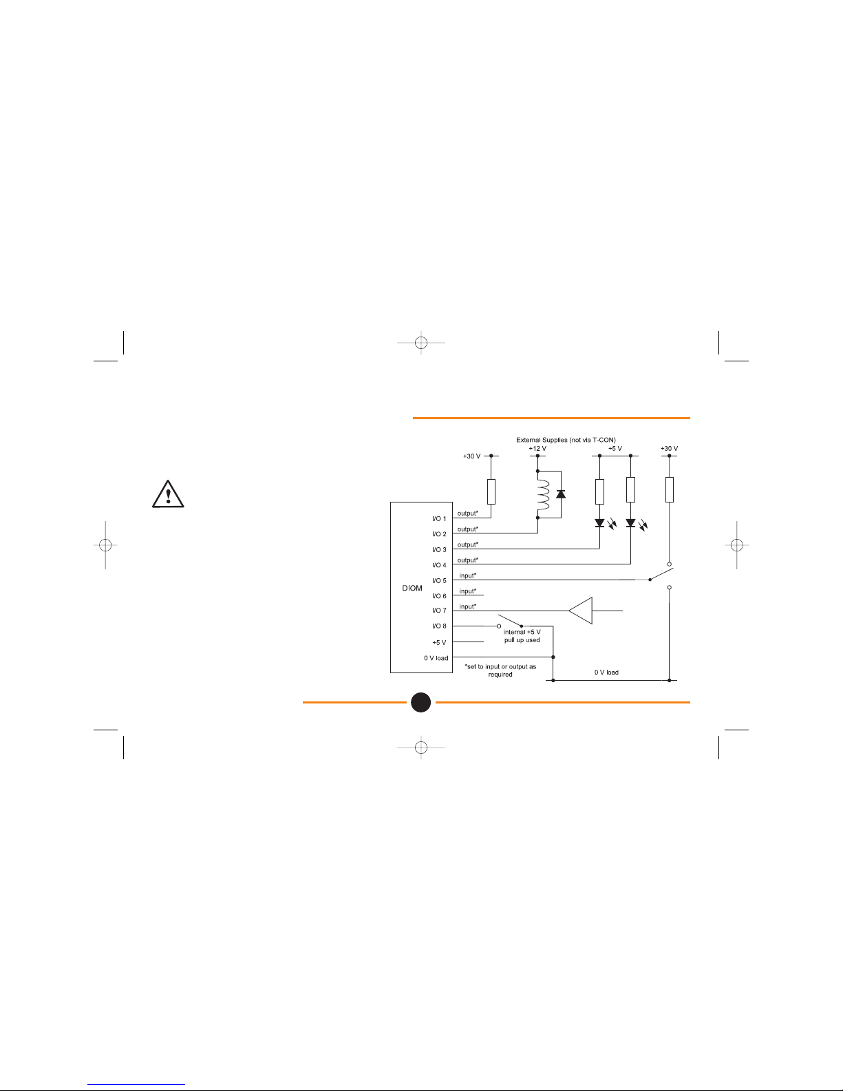
Connecting to the DIOM.
Example of wiring connections of the DIOM.
Inductive loads must be suppressed.
(i.e. protection diode.)
0V load must be connected to local 0V, to
minimise load return current through DIOM
and Orbit.
4.0: Application - Hardware
4.0 Application - Hardware
18
Manual No. 502237 Issue 2
DIOM 502237_Issue 2.qxd 20/07/2005 15:38 Page 18
Page 21

4.0: Application - Hardware
4.0 Application - Hardware
19
Manual No. 502237 Issue 2
EMC Immunity Enhancement Suggestions
If the DIOM is used in applications where there may be
higher than normal interference sources (i.e. near heavy
industrial machinery). Adopting some or all of the
following measures may enhance immunity
performance.
• Shielded cable (Braided) 360° screen to shell.
• Ferrite sleeves.
• Short cables.
• Route away from cables (the interference source).
• Where possible cross cables at right angles to
reduce coupling.
DIOM 502237_Issue 2.qxd 20/07/2005 15:38 Page 19
Page 22

Input / Output Control
DIOM Input / Output ports are read by OrbitRead1 and controlled by OrbitPreset. (Refer to Communications with
DIOM).
In the example below, Port 0 (bit 0) is driving a load and Port 1 (bit 1) is an input to a switch (All other Ports are not
used in this example).
All example input states are read back correctly except the last where Port 0 (bit 0) output driver is switched ON
causing a false input state to be read by the Port 0 input buffer.
Input and output ports are internally connected. For each I/O line, the output driver must be OFF (bit=1) before it can
be used as an input.
Note however that this last condition is an example of the DIOM monitoring its own output state.
5.0: Application - Software
5.0 Application - Software
20
Manual No. 502237 Issue 2
DIOM 502237_Issue 2.qxd 20/07/2005 15:38 Page 20
Page 23

5.0: Application - Software
5.0 Application - Software
21
Manual No. 502237 Issue 2
DIOM 502237_Issue 2.qxd 20/07/2005 15:38 Page 21
Page 24

Multiple readings
In some applications multiple readings of OrbitRead1 may be required i.e.:
External Electrical interference.
Switch bounce.
Noisy Supplies.
Mechanical vibration.
If a port is being used to read a switch condition for example, a single OrbitRead1 may have missed the event or may
have seen a noise spike in the place of the event.
A possible solution is to issue multiple OrbitRead1 commands to confirm the input status.
5.0: Application - Software
5.0 Application - Software
22
Manual No. 502237 Issue 2
DIOM 502237_Issue 2.qxd 20/07/2005 15:38 Page 22
Page 25

Return of Goods
Return of Goods
23
Manual No. 502237 Issue 2
Products returned for repair should be shipped prepaid to Solartron Metrology. The shipping container should be
marked: "Return for Repair"
Model ..... Type .....
The following information should accompany the product(s):
1. A purchase order, unless the product is being returned under warranty.
2. Application: type of environment and length of time in service of the product(s).
3. Description: the faulty operation of the product(s) and the circumstances of the failure.
4. Name and telephone number of the person to contact if there are questions about the returned product(s).
5. Statement as to whether warranty or non-warranty service is required.
6. Complete shipping instructions for the return of the product(s).
7. Original purchase order number and date of purchase.
Adherence to these procedures will expedite handling of the returned product(s) and will prevent unnecessary
additional charges for inspection and testing to determine the condition of the product(s).
Solartron reserves the right to repair or replace goods returned under warranty.
DIOM 502237_Issue 2.qxd 20/07/2005 15:38 Page 23
Page 26

France
Solartron Metrology,
Z.I. du Bois Chaland
2, rue du Bois Chaland
CE 5611 LISSES
91056 EVRY CEDEX
Tel: +33 (0)1 69 64 47 47
Fax: +33 (0)1 69 64 47 49
Germany
Solartron Metrology,
Wittekindstrasse 12
45470
Mülheim/Ruhr.
Tel: +49 (0) 208 31026
Fax: +49 (0) 208 31441
United Kingdom
Solartron Metrology,
Steyning Way,
Bognor Regis,
West Sussex. PO22 9ST
Tel: +44 (0) 1243 833333
Fax: +44 (0) 1243 833332
U.S.A.
Solartron Metrology,
10770 Hanover Road,
Forestville, NY 14062
Tel: +1 (716) 965-4100
Fax: +1 (716) 965-4144
Solartron pursues a policy of continuous development. The specifications in this document may therefore be changed without notice Solartron Metrology. A Roxboro Group Company
solar
tron
OFFICES WORLDWIDE - Addresses for Repairs
Email: sales@solartronmetrology.com
Web: www.solartronmetrology.com
SOLARTRON METROLOGY OFFICES
DIOM 502237_Issue 2.qxd 20/07/2005 15:38 Page bcov1
 Loading...