

Page 1

1250
1250
Frequency Response
Analyzer
OPERATING MANUAL
Page 2

1250 Frequency Response Analyzer
1250
Solartron is a division of Solartron Group Ltd. Any reference to Schlumberger or
Schlumberger Instruments (the name of the company until November 1993) implies no
liability on the part of Schlumberger.
Solartron Solartron
Victoria Road, Farnborough 19408 Park Row, Suite 320
Hampshire, GU14 7PW England Houston, Texas 77084-4860, USA
Telephone: +44 (0)1252 376666 Telephone: +1 281 398 7890
Fax: +44 (0)1252 544981 Fax: +1 281 398 7891
Toll-free: 1-800 CALL SOL
Solartron Solartron
37 Rue du Saule Trapu Beijing Liasion Office
91882 MASSY, Cedex Room 327 Ya Mao Building
France No. 16, Bei Tu Chen Xi Road
Telephone: +33 (0)1 69 53 63 53 Beijing 100101, PR China
Fax: +33 (0)1 60 13 37 06 Telephone: +86 10-6238 4687
Fax: +86 10-6202-8617
E-mail: solartron@solartron.com
Web: http://www.solartron.com
For details of our agents in other countries, please contact our Farnborough, UK, office.
Solartron pursues a policy of continuous development and product improvement.
The specification in this document may therefore be changed without notice.
Page 3

1250 Frequency Response Analyzer
1250
DECLARATION OF CONFORMITY
The directives covered by this declaration
73123/EEC Low voltage Equipment Directive, amended by 93/68/EEC
89/336/EEC Electromagnetic Compatibility Directive, amended by 92/31/EEC & 93/68/EEC
Product(s)
1250A Frequency Response Analyzer
The following products are included in this declaration:
1250B, 1250E and 1254 Frequency Response Analyzers;
12501A, 12502A, 12506A, 12506B, 12506C Option modules.
Basis on which conformity is being declared
The product(s) identified above comply with the requirements of the EU directives
by meeting the following standards:
BS EN50081-1:1992 Electromagnetic Compatibility - Generic Emission Standard
Part 1: Residential, commercial and light industry.
BS EN50082-1:1992 Electromagnetic Compatibility - Generic Immunity Standard
Part 1: Residential, commercial and light industry.
EN61010-1:1993 Safety requirements for electrical equipment for
measurement, control and laboratory use.
Accordingly the CE mark has been applied to this product.
Signed
For and behaIf of Solartron, a division of Solartron Group Limited
Authority: Engineering Manager
Date: December 1995
REGISTERED IN ENGLAND No.2852989. REGISTERED OFFICE: BYRON HOUSE,
CAMBRIDGE BUSINESS PARK, CAMBRIDGE, CB4 4WZ
Approved to BS EN ISO 9001:1994 and BS EN 123000, MOD Registered Company
A Roxboro Group company
Solartron
a division of Solartron Group Ltd
Victoria Road, Farnborough
Hampshire GUI4 7PW England
Tel +44 (0) 1252 376666
Fax +44 (0) 1252 543854
Page 4

1250 Frequency Response Analyzer
1250
GENERAL SAFETY PRECAUTIONS
The equipment described in this manual has been designed in accordance with EN61010
“Safety requirements for electrical equipment for measurement, control and laboratory use”,
and has been supplied in a safe condition. To avoid injury to an operator or service
technician the safety precautions given below, and throughout the manual, must be strictly
adhered to, whenever the equipment is operated, serviced or repaired. For specific safety
details, please refer to the relevant sections within the manual.
The equipment is designed solely for electronic measurement and should be used for no
other purpose. Solartron Instruments accept no responsibility for accidents or damage
resulting from any failure to comply with these precautions.
ENVIRONMENT
This instrument must always be used within the environmental conditions (temperature,
humidity, vibration, etc.), given in the Specification.
GROUNDING
To minimize the hazard of electrical shock it is essential that the equipment is connected to
a protective ground whenever the power supply, measurement or control circuits are
connected, even if the equipment is switched off. The protective ground for ac and dc
supplies is connected separately.
AC GROUND is connected via the ac supply cord. The cord must be plugged into an ac line
outlet with a protective ground contact. When an extension lead is used, this must also
contain a ground conductor. Always connect the ac supply cord to the supply outlet before
connecting the control and signal cables; and, conversely, always disconnect control and
signal cables before disconnecting the ac supply cord. The ac ground connection must be
capable of carrying a current of 25A for a minimum of one minute.
AC SUPPLY VOLTAGE
Never operate the equipment from a line voltage or frequency in excess of that specified.
Otherwise, the insulation of internal components may break down and cause excessive
leakage currents.
FUSES
Before switching on the equipment check that the fuses accessible from the exterior of the
equipment are of the correct rating. The rating of the ac line fuse must be in accordance
with the voltage of the ac supply.
Should any fuse continually blow, do not insert a fuse of a higher rating. Switch the
equipment off, clearly label it “unserviceable” and inform a service technician.
EXPLOSIVE ATMOSPHERES
NEVER OPERATE the equipment, or any sensors connected to the equipment, in a
potentially explosive atmosphere. It is NOT intrinsically safe and could possibly cause an
explosion.
Continued overleaf.
Page 5
1250 Frequency Response Analyzer
1250
SAFETY PRECAUTIONS (continued from previous page)
SAFETY SYMBOLS
For the guidance and protection of the user, the following safety symbols appear on the
equipment:
SYMBOL MEANING
Refer to operating manual for detailed instructions of use. In
particular, note the maximum voltages permissible at the input
sockets, as detailed in the Specification.
Hazardous voltages.
NOTES, CAUTIONS AND WARNINGS
For the guidance and protection of the user, Notes, Cautions and Warnings appear
throughout the manual. The significance of these is as follows:
NOTES highlight important information for the reader’s special attention.
CAUTIONS guide the reader in avoiding damage to the equipment.
WARNINGS guide the reader in avoiding a hazard that could cause injury or death.
AVOID UNSAFE EQUIPMENT
The equipment may be unsafe if any of the following statements apply:
• Equipment shows visible damage.
• Equipment has failed to perform an intended operation.
• Equipment has been subjected to prolonged storage under unfavorable conditions.
• Equipment has been subjected to severe physical stress.
If in any doubt as to the serviceability of the equipment, don’t use it. Get it properly checked
out by a qualified service technician.
LIVE CONDUCTORS
When the equipment is connected to its measurement inputs or supply, the opening of
covers or removal of parts could expose live conductors. The equipment must be
disconnected from all power and signal sources before it is opened for any adjustment,
replacement, maintenance or repair. Adjustments, maintenance or repair, must be done
only by qualified personnel, who should refer to the Maintenance Manual.
EQUIPMENT MODIFICATION
To avoid introducing safety hazards, never install non-standard parts in the equipment, or
make any unauthorized modification. To maintain safety, always return the equipment to
Solartron for service and repair.
Page 6

1
Contents
Section Page
Chapter 1 General Information
1.1 Introduction 1.3
1.2 Basic measuring set-up 1.3
1.3 The instrument essentials 1.4
1.4 Additional facilities 1.5
1.5 1250 Variants 1.7
1.6 Options 1.8
Chapter 2 Installation
2.1 Safety 2.2
2.2 General Safety Precautions 2.2
2.2.1 Electromagnetic Compatibility 2.3
2.3 Connecting the ac mains 2.4
2.3.1 Safety precautions: Earthing 2.4
2.3.2 Procedure 2.4
2.4 Accessories 2.5
2.5 Rack Mounting 2.5
2.5.1 Rack Dimensions 2.6
2.5.2 Ventilation 2.6
2.5.3 Fitting Telescopic Slide Mounting Kit 12505B (Accuride) 2.6
2.5.4 Fitting Telescopic Slide Mounting Kit 12505C (Jonathan) 2.11
Chapter 3 Switching on and Initialising
3.1 Switch On 3.2
3.2 Initialising 3.3
3.3 Resetting 3.4
Chapter 4 Making Measurements: The Generator
4.1 Simple Measurements 4.2
4.2 Setting the Generator 4.2
4.2.1 Introduction 4.2
4.2.2 Setting the Generator Menu 4.2
4.2.3 Waveform 4.2
4.2.4 Frequency 4.3
4.2.5 Clear 4.4
4.2.6 Amplitude 4.4
4.2.7 Bias 4.4
4.2.8 Modulated Carrier 4.4
4.3 Checking Generator Settings: Using the Status Displays 4.4
4.4 Starting the Generator 4.5
4.4.1 Generator Start Key 4.5
4.4.2 Generator Waveform Starting Point 4.5
4.5 Rack Stopping the Generator 4.5
4.5.1 Introduction 4.5
4.5.2 Generator Stop Key 4.5
Page 7

Contents 1250 Frequency Response Analyzer
2 1250
4.5.3 Generator Stop @ Key 4.6
4.5.4 Applications of the Stop @ Key 4.6
4.5.5 Generator Overload Protection 4.7
Chapter 5 Making Measurements: The Analyzers
5.1 Introduction 5.2
5.2 Setting the [ANALYZER COMMON] Menu 5.2
5.2.1 ∫ Time 5.2
5.2.2 Delay 5.3
5.2.3 Harmonic 5.3
5.2.4 Order 5.4
5.2.5 Auto ∫ 5.4
5.2.6 Application of Auto Integration 5.4
5.3 Setting Individual Analyzers 5.6
5.3.1 Range 5.6
5.3.2 Demod 5.6
5.3.3 Coupling 5.6
5.3.4 Input 5.6
5.4 Measurement Start 5.7
5.5 Stopping the Analyzer; Stop and Break Keys 5.8
5.6 Changing Menus during Recycle 5.8
5.7 Measurement Start Point 5.8
5.7.1 Implementation of Delay 5.8
Chapter 6 The Sweep Facility
6.1 Introduction 6.2
6.2 Logarithmic Sweep 6.2
6.3 Linear Sweep 6.2
6.4 Setting Up a Logarithmic or Linear Sweep 6.3
6.5 Executing the Sweep 6.3
6.6 Automatic Sweep Time 6.3
6.7 End of Sweep Conditions 6.4
6.8 Further Sweeps 6.4
6.9 Stopping and Re-staring the Sweep 6.4
6.9.1 Introduction 6.4
6.9.2 Commands Which Produce “Sweep Stop” Status 6.4
6.9.3 Commands Which Produce “Sweep Idle” or “Hold” Status 6.5
6.10 Changing Parameters in Mid-Sweep 6.5
6.11 Harmonic Sweep 6.5
6.11.1 Introduction 6.5
6.11.2 Perfoming a harmonic Sweep 6.6
6.11.3 Error 21 6.6
6.11.4 Sweep Termination Conditions 6.6
Chapter 7 The Display Menu and Mini Status
7.1 Introduction 7.2
7.2 Sources 7.3
7.3 Co-Ordinates 7.3
Chapter 8 Menu Summary
8.1 Introduction 8.2
Chapter 9 Additional Generator Controls
9.1 The Variable Key 9.2
9.1.1 Introduction 9.2
Page 8

1250 Frequency Response Analyzer Contents
1250 3
9.1.2 Methods of Use 9.2
9.1.3 Method 1, With Analyzers Stopped 9.2
9.1.4 Method 2, With Analyzers Running 9.3
9.1.5 Using Variable with the Generator STOP @ Key 9.4
9.2 Amplitude Compression 9.5
9.2.1 Introduction 9.5
9.2.2 Principle of Operation 9.5
9.2.3 Generator Output Limit 9.7
9.2.4 Setting the Menu 9.8
9.2.5 Error 84 9.8
9.2.6 Use of the File 9.8
Chapter 10 Facilities For More Complex Measurements
10.1 The Function Key 10.2
10.1.1 Introduction 10.2
10.1.2 Angle Information 10.3
10.1.3 Multiplication Factors: Xωn 10.4
10.1.4 Scaling 10.5
10.1.5 Limits 10.6
10.1.6 Function Key Summary 10.7
10.2 Data Flow Schematic 10.8
Chapter 11 Additional Displayed Information
11.1 The Status Key 11.2
11.1.1 Introduction 11.2
11.1.2 Using the Key 11.2
11.1.3 Main Status 11.3
11.1.4 Other Status 11.5
11.1.5 Printed Record 11.8
11.2 Error Codes 11.9
11.2.1 Introduction 11.9
11.2.2 Error Codes: Summary 11.9
11.3 Error Codes: Details 11.11
11.3.1 Introduction 11.11
11.3.2 Group 0. Errors Pertaining to Command Structure 11.11
11.3.3 Group 1. Errors Pertaining to the Learnt Program 11.12
11.3.4 Group 2. Parametric Interaction Errors. 11.12
11.3.5 Group 3. Generator Warnings and Errors 11.12
11.3.6 Group 4. Learnt Program, File and Variable 11.13
11.3.7 Group 5. Missing Boards 11.13
11.3.8 Group 6. Illegal I/O Manipulation 11.14
11.3.9 Group 7. System Errors 11.14
11.3.10 Group 8. Measurement Validity is Suspect 11.14
Chapter 12 Recording, Learning and Storing Facilities
12.1 The Data Output Key 12.2
12.1.1 Introduction 12.2
12.1.2 [DATA OUTPUT] 12.2
12.1.3 [FORMAT]: Heading and Reformat 12.3
12.1.4 Heading 12.3
12.1.5 Reformat 12.4
12.1.6 Menu Changes Activating the Heading and Reformat Functions 12.5
12.1.7 Channel and Range Column Conventions 12.5
12.1.8 [GPIB CONFIGURE] 12.6
12.1.9 Parallel and Poll Sense 12.6
12.1.10 Serial Poll 12.6
Page 9

Contents 1250 Frequency Response Analyzer
4 1250
12.1.11 Terminator and Separator 12.6
12.2 The File 12.7
12.2.1 Introduction 12.7
12.2.2 Maximum File Size 12.7
12.2.3 Selecting File Size 12.7
12.2.4 Overwriting the Size of the File 12.7
12.2.5 Starting a File 12.8
12.2.6 Reading from the File 12.8
12.3 Learnt Programs 12.9
12.3.1 Introduction 12.9
12.3.2 Learning a Program: From the Front Panel 12.9
12.3.3 Learning a Program: From an External Device 12.10
12.3.4 Executing a Program 12.11
12.3.5 Editing a Program: From the Front Panel 12.11
12.3.6 Editing a Program: From an External Device 12.12
12.3.7 Copying a Program 12.12
12.3.8 Program Pause/Continue Key 12.13
12.3.9 Example Programs 12.13
12.3.10 Error Messages Displayed During Program Running 12.13
12.4 X - Y Plotter 12.14
12.4.1 Introduction 12.14
12.4.2 Setting up a Plot: Non-Plotter Menus 12.14
12.4.3 The [PLOTTER COMMON] menu 12.15
12.4.4 The [PLOTTER X-AXIS] and [PLOTTER Y-AXIS] menus 12.16
12.4.5 The [PLOTTER SCALING] menu 12.17
12.4.6 Performing a Plot 12.18
12.4.7 Bode and Nyquist Plots 12.19
12.4.8 Adjusting the Plotting Field to suit Preprinyed Chart Paper 12.20
12.4.9 Pen Selection with two Pen Plotters 12.21
12.4.10 Plotting Data from the File 12.21
Chapter 13 The RS423 and GPIB Ports. Remote Control
13.1 Introduction 13.3
13.1.1 GPIB Capacity Code 13.3
13.2 Connections 13.4
13.3 RS423 Baud Rate 13.4
13.4 RS423 Input Command Terminator Character; RS423 Character
Frame 13.4
13.5 GPIB Switches 13.5
13.5.1 Address switches 13.6
13.5.2 Input Command Terminator Character Switches 13.6
13.5.3 Talk Only Switch 13.6
13.5.4 GPIB Switch Example 13.6
13.6 REMOTE/LOCAL Facility 13.7
13.6.1 Local Lock-Out 13.8
13.7 Command Codes 13.9
13.7.1 Introduction 13.9
13.7.2 Command Code Format 13.9
13.7.3 Generator Commands 13.10
13.7.4 Synchroniser Commands 13.10
13.7.5 Amplitude Compression Commands 13.11
13.7.6 Auxiliary Generator Commands 13.11
13.7.7 Analyzer Commands 13.11
13.7.8 Sweep Commands 13.12
13.7.9 Display Commands 13.12
Page 10

1250 Frequency Response Analyzer Contents
1250 5
13.7.10 Plotter Commands 13.12
13.7.11 Status Commands 13.13
13.7.12 Variable Commands 13.13
13.7.13 File Commands 13.13
13.7.14 Program Commands 13.14
13.7.15 Data Output Commands 13.14
13.7.16 RS423/GPIB Commands 13.14
13.7.17 Function Commands 13.15
13.7.18 Miscellaneous Commands 13.15
13.7.19 Self Test Commands 13.16
13.7.20 Commands in Alphabetical Order 13.16
13.8 GPIB Controller: Language Used in Program Examples 13.19
13.9 Command Query 13.19
13.10 Measurement Output Selection 13.20
13.10.1 Via RS423 Port 13.20
13.10.2 Via GPIB Interface 13.21
13.11 Measurement Output Rate 13.21
13.11.1 Via RS423 Port 13.21
13.11.2 Via GPIB Interface 13.21
13.12 Measurement Output Format 13.21
13.12.1 RS423 Port 13.21
13.12.2 GPIB Talk Only Mode 13.21
13.12.3 GPIB Normal Mode 13.22
13.12.4 Dump Mode 13.23
13.12.5 Floating Point Format 13.23
13.12.6 Output Terminators and Separators 13.24
13.13 Serial Poll/Parallel Poll 13.25
13.13.1 Serial Poll 13.25
13.13.2 Parallel Poll 13.26
13.14 Learnt Programs. External Storing and Reloading 13.27
13.14.1 RS423 Port, Device Control Characters 13.27
13.14.2 Procedure for Storing a Learnt Program Externally, via RS423 13.28
13.14.3 Procedure of Loading a Learnt Program into the 1250,
Via RS423 Port 13.28
13.14.4 Procedure of Loading a Learnt Program into the 1250,
Via GPIB Port 13.28
13.14.5 Example of Controller Program for Transferrring Learnt program 1
from 1250 via GPIB Port, Without Handshake 13.29
13.14.6 Example of Controller Program for Transferrring Learnt program 1
from 1250 via GPIB Port, With Handshake 13.29
13.14.7 Reloading a Learnt Program to 1250 Via GPIB 13.29
13.15 File Output 13.30
13.15.1 Procedure to Outputt File Via RS423 Port by External Command 13.30
13.15.2 Procedure to Output the File Via GPIB Port 13.30
13.15.3 Example of Controller program for Copying the File to the GPIB
Without Handshake 13.31
13.15.4 Example of Controller program for Copying the File to the GPIB
With Handshake 13.31
13.16 GPIB Plotting 13.31
13.16.1 Operating Sequence for GPIB Plotter, Using a Controller 13.32
13.17 Combinations of RS423 and GPIB Devices 13.32
Chapter 14 Break, Self Test, Time Display and Power Fail
14.1 The Break Key 14.2
14.2 Self Test 14.2
14.3 Time Display 14.4
Page 11

Contents 1250 Frequency Response Analyzer
6 1250
14.4 Power Fail 14.5
Chapter 15 Options
15.1 Synchroniser Unit 12501 15.2
15.1.1 Introduction 15.2
15.1.2 Description 15.2
15.1.3 Installation 15.2
15.1.4 Connecting Up 15.2
15.1.5 Modes of Operation 15.3
15.1.6 The Synchroniser Menu 15.5
15.1.7 Procedure for Establishing the Sync. Locked State 15.8
15.1.8 Synchroniser Status 15.9
15.1.9 Measuring Harmonics: Use of Order Analysis 15.11
15.2 Modulator/Demodulator Unit 12502 15.12
15.2.1 Introduction 15.12
15.2.2 Installation 15.12
15.2.3 Connections 15.12
15.2.4 Setting Up 15.12
15.3 Analog Plotter Interface 12503 15.13
15.2.1 Introduction 15.13
15.2.2 Installation 15.13
15.2.3 Preset Controls 15.14
15.2.4 Setting Up and Performing a Plot 15.14
15.4 Auxiliary generator Unit 12505 15.15
15.4.1 Introduction 15.15
15.4.2 Description 15.15
15.4.3 Installation 15.15
15.4.4 Setting Up 15.16
Chapter 16 The 1251 Multichannel Analyzer System
16.1 Introduction 16.2
16.2 Description 16.2
16.3 System Configuration 16.2
16.3.1 1250-1251 Interface Bus 16.2
16.3.2 IEEE 488 Interface Bus 16.2
16.3.3 1250 Series Options 16.2
16.4 Connecting Up 16.4
16.4.1 Safety: Connecting the ac Mains 16.4
16.4.2 Connecting up the 1250-1251 Interface Bus 16.4
16.5 1251 Unit Identification Switches 16.5
16.5.1 Analyzer Channel Numbering 16.5
16.6 Manual Operation of the System 16.5
16.6.1 Introduction 16.5
16.6.2 Manual Setting up of the 1251 System 16.5
16.6.3 Setting up the 1251 Analyzers 16.6
16.6.4 Displaying and Plotting data from the 1251 Analyzers 16.6
16.6.5 Checking the Analyzer and Display/Plotter Menu Settings 16.7
16.7 Remote Operation of the System 16.7
16.7.1 Introduction 16.7
16.7.2 GPIB Capability Code 16.7
16.7.3 Setting up the GPIB Configure Menu 16.8
16.7.4 Data Transfer Speeds 16.8
16.7.5 GPIB Output Buffers 16.8
16.7.6 GPIB Addresses 16.9
16.7.7 1251 Multichannel Analyzer Output: Complete Block Format 16.9
16.7.8 ASII Format 16.9
Page 12

1250 Frequency Response Analyzer Contents
1250 7
16.7.9 Dump Mode Format 16.10
16.8 1251 Multichannel Analyzer Specification 16.11
Chapter 17 Specification
Index
Page 13

CWB / 1260_Op / Issue 9 1-1
1
General Information
Section Page
1.1 Introduction 1.3
1.2 Basic measuring set-up 1.3
1.3 The instrument essentials 1.4
1.4 Additional facilities 1.5
1.5 1250 variants 1.7
1.6 Options 1.8
Page 14

General Information 1250 Frequency Response Analyzer
1-2 CWB / 1250_Op / Issue 9
Page 15
1250 Frequency Response Analyzer Menu Terms
CWB / 1250_Op / Issue 9 1-3
1.1 INTRODUCTION
The 1250 Frequency Response Analyzer measures the gain and phase characteristics
of the system under test, when stimulated by a known sinusoid. Ease of use is provided
by the touch-sensitive front panel keys. Many advanced features are incorporated,
making full use of microprocessor technology.
Standard interfaces allow full remote control. Readings can be stored for future
processing or fed to external recording devices. The instrument can be either freestanding or rack-mounted. Diagrams showing the front and rear panels are shown at the
end of this Chapter.
Figure 1.1 - 1250 Frequency Response Analyzer
1.2 BASIC MEASURING SET-UP
Figure 1.2 - Basic Measuring Set-up
Page 16
General Information 1250 Frequency Response Analyzer
1-4 CWB / 1250_Op / Issue 9
1.3 THE INSTRUMENT ESSENTIALS
The three main sections of the 1250 are:
1. A Generator which produces a sinusoidal, square, or triangular-wave electrical
stimulus for the system on test.
2. Two analyzers which measure the response to the stimulus at two points in the
system, enabling either of the following to be calculated and displayed:
a) Single Point measurements (i.e., the absolute voltage of either Channel, and its
phase with respect to the Generator) as shown in Fig. 1.3:
Figure 1.3 - Single Point Measurements
b) Point-to-Point measurements (e.g., the response of Ch.2 with respect to Ch.1, in
terms of gain and phase shift) as shown in Fig. 1.4:
Figure 1.4 - Point-to-Point Measurements
Page 17
1250 Frequency Response Analyzer Menu Terms
CWB / 1250_Op / Issue 9 1-5
3. The Display, (which is not fitted to 1250B), shows the results of the measurements in
any one of the following co-ordinate systems:
a. Cartesian (a, jb)
b. Polar (r, θ )
c. Log Polar (log r, θ )
The results may also be stored within the instrument for further processing. Additionally,
results may be passed to a plotter or computer.
1.4 ADDITIONAL FACILITIES
These are shown in Fig. 1.5
Figure 1.5 - 1250 Block Schematic
Page 18
General Information 1250 Frequency Response Analyzer
1-6 CWB / 1250_Op / Issue 9
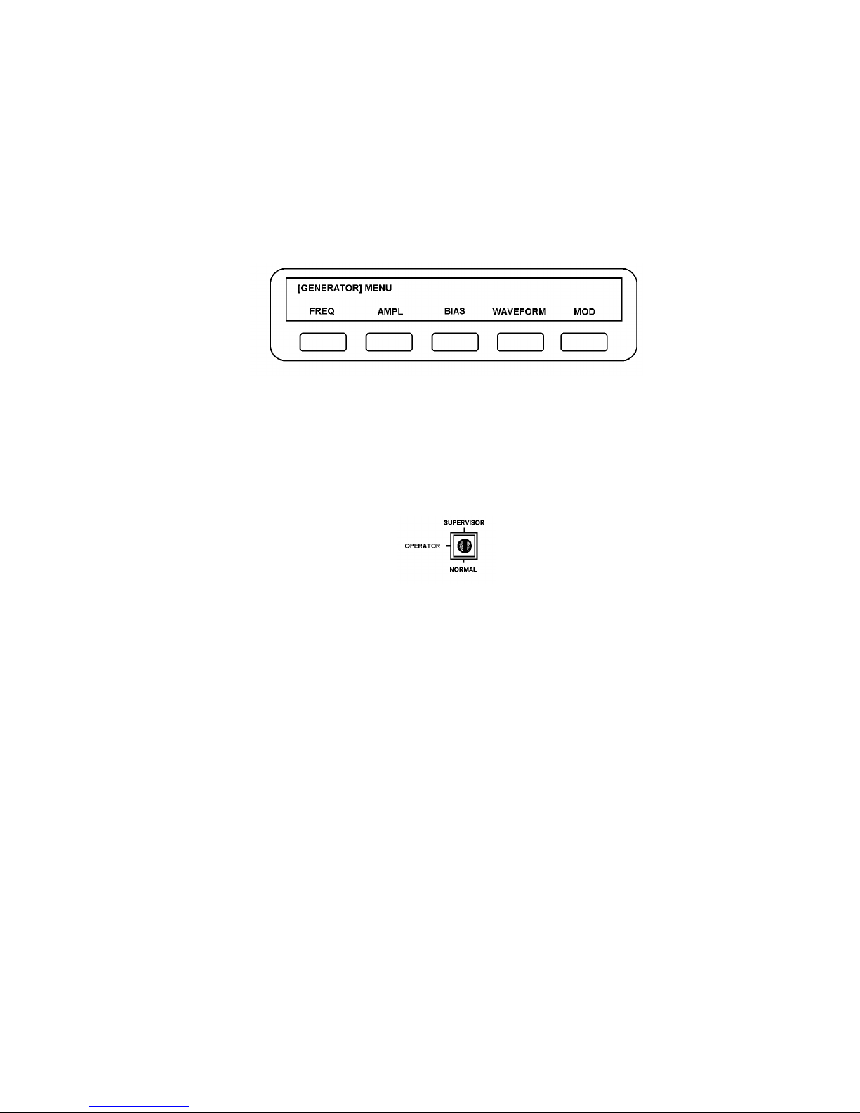
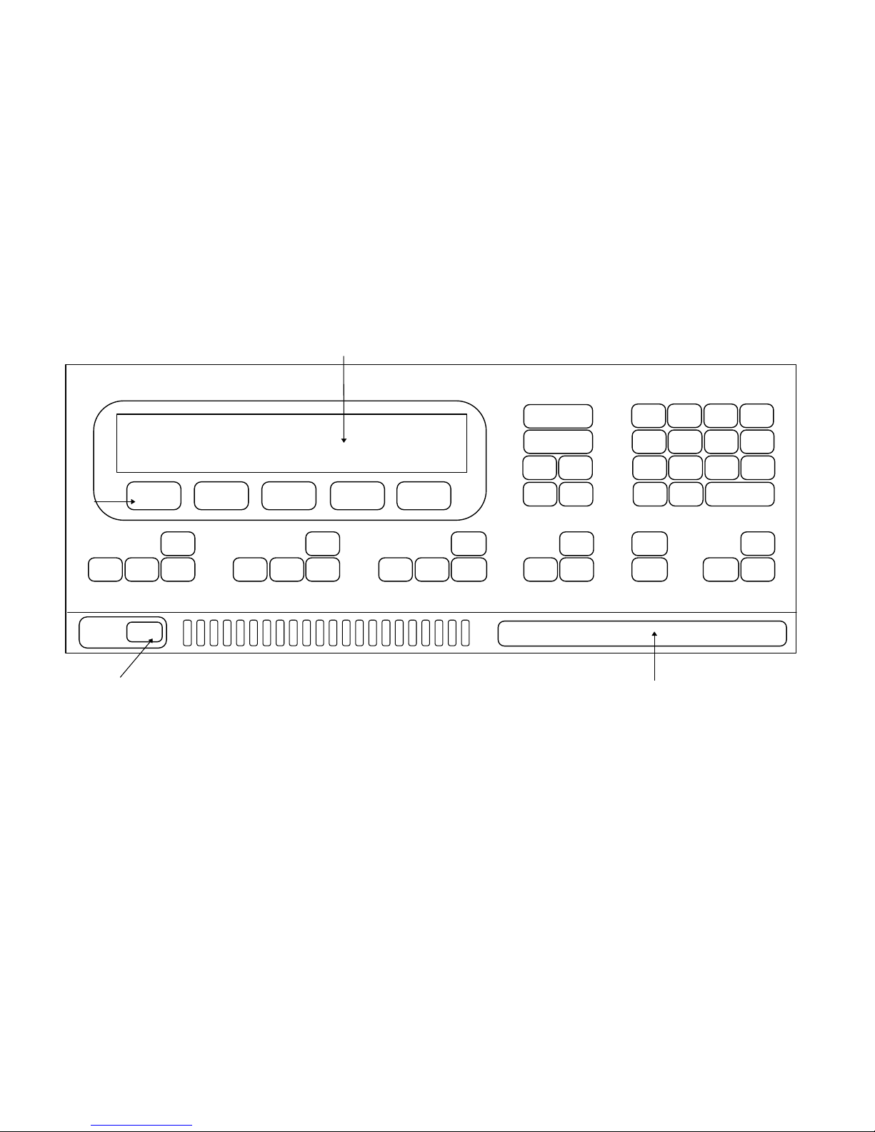
Keyboard. The keyboard on the front panel uses membrane switches and consists of a
number of function keys, used in conjunction with a numeric keypad. (See Fig. 1.7).
The function keys are known as `hard` keys in order to distinguish them from the five
keys immediately below the display which are called `soft` keys. Each hard key is
dedicated to one specific task, whereas the soft keys have many different roles assigned
to them, according to which hard key has just been operated. These roles are identified
by titles which appear in the display immediately above the relevant soft key.
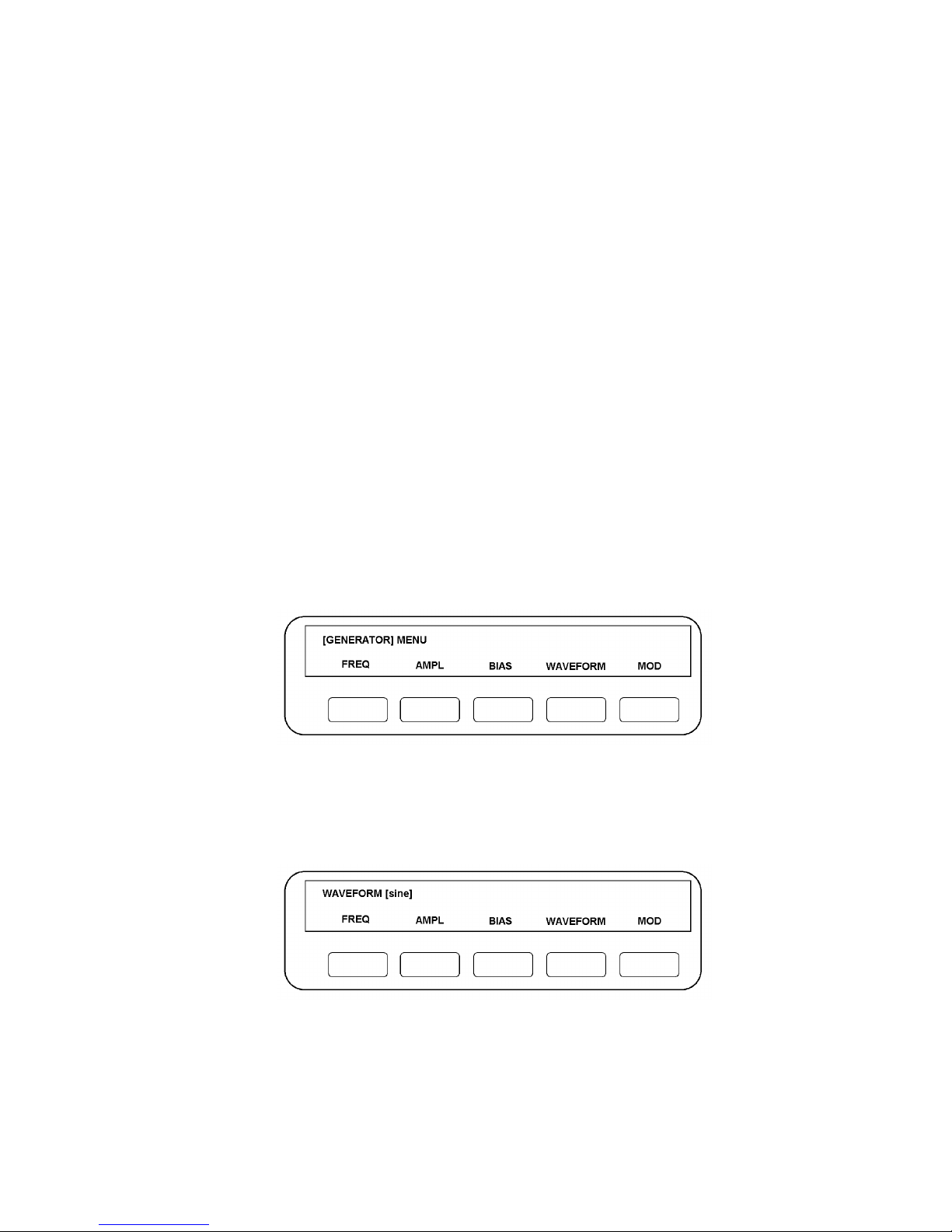
For example, the major programmable sections of the 1250 are each controlled by a
menu. If the GENERATOR MENU key is pressed, the lower half of the display will
assign titles to the five soft keys as shown in Fig. 1.6:
Figure 1.6 - Softkey titles
Display. The display is a vacuum fluorescent alpha numeric type, each character being
formed on a 7 x 5 dot matrix. There are two rows of forty characters each.
Keyswitch. The keyswitch on the rear panel of the 1250 enables/disables writing to the
permanent memory, when switched to Supervisor/Normal respectively. The keyswitch
is a three position switch, with the Operator position reserved for future use.
GPIB Interface. Permits any device conforming to IEEE 488 (1978) to be connected,
e.g., a digital plotter to display results or a computer to process them.
Serial Interface. Enables most EIA RS232C and RS423 compatible peripherals to be
connected.
Control and Computation. This section controls the functioning of the whole
instrument and computes the results of the measurements. All the functions are under
microprocessor control and the entire instrument is run synchronously to preserve the
highest possible accuracy and repeatability of results. There are stores to hold previous
readings, parameter settings, and a number of learnt programs.
Page 19

1250 Frequency Response Analyzer Menu Terms
CWB / 1250_Op / Issue 9 1-7
1.5 1250 VARIANTS
The 1250 is available in several versions, as shown in the table:
Model Number of
Channels
Front Panel
control
Compliant with
European EMC
Regulations
Notes
1250A 2 Yes No
1250B 2 No Yes
1250E 2 Yes Yes
1250N 2 Yes No Low impedance
generator output
1254A 4 Yes Yes
1251A Multiple n/a No Multi-channel
extension for
1250
Page 20

General Information 1250 Frequency Response Analyzer
1-8 CWB / 1250_Op / Issue 9
1.6 OPTIONS
All these are controllable from the 1250 Keyboard, as are the GPIB and Serial Interface.
1. Synchroniser (12501A)*: enables the 1250 to be synchronised to an external
source.
2. Modulator/Demodulator (1250A): enables the 1250 to be directly interfaced with
systems that require ac carrier inputs, or which produce ac carrier outputs.
3. Plotter Interface (12503A)*: enables the 1250 to plot the measured results on an
analog plotter. A digital plotter may be driven from the GPIB.
4. Auxiliary Generator*: an additional generator, synchronised to the main generator
but producing a signal in quadrature with it. If required, however, the two generators
can be in phase. Three variants of the Auxiliary Generator are available:
Cosine (Quadrature) - 12506A
Sine (In phase) - 12506B
Antiphase - 12506C
* - these options are not available with the 1250N. In the manual, any references to the
options are not therefore applicable to 1250N.
1250A, B and E can be fitted with up to three options, plus one auxiliary generator.
1254A can only be fitted with any one of the available options, and cannot use an
auxiliary generator.
With the exception of the 12503A (which is no longer available in Europe), all the
options are compliant with European EMC standards. Therefore 1250B, 1250E and
1250A remain compliant when fitted with these options.
Page 21
CWB / 1260_Op / Issue 9 1-9
Figure 1.7 - 1250E Front Panel
Alpha-numeric display
Front Input connections
(not available on 1250E, 1250B or 1254A)
Soft keys
Power switch
SI1250
FREQUENCY RESPONSE ANALYZER
POWER
OFF ON
STOP
STOP
@
START
MENU
STOP SINGLE RECYCLE
MENU
STOP HOLD
START/
CONTINUE
MENU
STOP PLOT
MENU
DATA
OUTPUT
FUNCTION
PAUSE/
CONTINUE
EXECUTE
LEARN
3 +/-
6
EXP
9
CLEAR
1 2
4 5
7 8
ENTER
. 0
STATUS VIEWFILE
LOCAL BREAK
VARIABLE
SELECT
[ ]
self test
GENERATOR ANALYSER SWEEP
DISPLAY/
PLOTTER
PROGRAM
Page 22
General Information 1250 Frequency Response Analyzer
1-10 CWB / 1250_Op / Issue 9
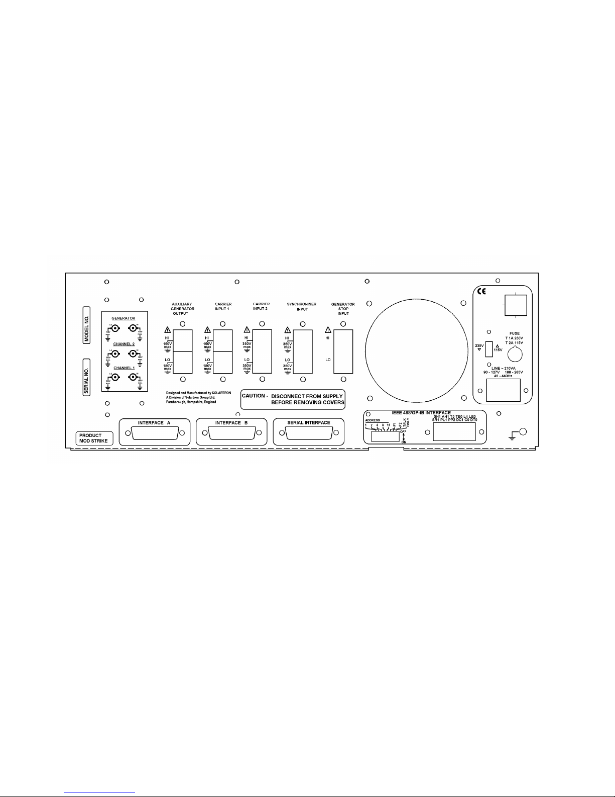
Note: The rear panel shown is for 1250E or 1250B. Other versions of 1250 may have a slightly different appearance.
Figure 1.8 - Rear panel layout
Page 23

1250 Frequency Response Analyzer Installation
CWB / 1250_Op / Issue 9A 2-1
2
Installation
Section Page
2.1 Safety 2.2
2.2 General Safety Precautions 2.2
2.2.1 Electromagnetic Compatibility 2.3
2.3 Connecting the ac mains 2.4
2.3.1 Safety precautions: Earthing 2.4
2.3.2 Procedure 2.4
2.4 Accessories 2.5
2.5 Rack Mounting 2.5
2.5.1 Rack Dimensions 2.6
2.5.2 Ventilation 2.6
2.5.3 Fitting Telescopic Slide Mounting Kit 12505B (Accuride) 2.6
2.5.4 Fitting Telescopic Slide Mounting Kit 12505C (Jonathan) 2.11
Page 24

Installation 1250 Frequency Response Analyzer
2-2 CWB / 1250_Op / Issue 9A
2.1 SAFETY
The 1250 has been designed in accordance with EN61010, "Safety requirements for
electrical equipment for measurement, control and laboratory use", and has been
supplied in a safe condition. This operating manual contains information and warnings
which must be followed by the user to ensure safe operation and to retain the equipment
in a safe condition.
The operating instructions include safety precautions where appropriate, but the
principal ones are also listed below.
2.2 GENERAL SAFETY PRECAUTIONS
1. Before switching on, ensure that the mains lead is connected to the ac supply in
accordance with the colour code.
2. Ensure that the mains voltage selector is correctly set.
3. Ensure that the mains plug is connected only to a mains outlet which has a protective
earth contact. This applies equally if an extension lead is used; the lead must
contain an earth conductor.
4. To effect earthing, the mains plug must be inserted before connections are made to
measuring and control circuits. The mains plug or external earth (as appropriate)
must remain connected until all measuring and control circuits have been
disconnected.
5. Any interruption of the earth connection (inside or outside the 1250) is prohibited.
6. When the 1250 is connected to its supply the opening of covers or removal of parts
could expose live conductors. The 1250 should be disconnected from all voltage
sources before it is opened for any adjustment, replacement, maintenance or repair.
Adjustments, maintenance or repair of the 1250 when it is powered should not be
attempted by the user. Consult a Solartron Service Centre if repairs are necessary.
7. Ensure that only fuses of the correct rating and of the specified type are fitted.
Makeshift fuses and short-circuiting of fuseholders is prohibited.
8. Whenever it is likely that the protection of the 1250 has been impaired, it should be
made inoperative and secured against any unintended operation. Protection could be
impaired if the 1250:
i) shows visible damage;
ii) has not been used as specified;
iii) has been operated outside the stated temperature range;
iv) fails to perform the intended measurements;
v) has been subjected to prolonged storage under unfavourable conditions;
vi) has been subjected to severe transport stress.
9. This symbol on the 1250 means 'Refer to the Operating Manual' for detailed
instructions or safety precautions.
In particular, care must be taken not to apply voltages in excess of the maximums
specified for each input and output. A summary of these is listed in the table below:
Page 25

1250 Frequency Response Analyzer Installation
CWB / 1250_Op / Issue 9A 2-3
Input / Output Maximum Voltage
Generator outputs 150V, HI or LO to Gnd
Channel inputs 500 V, HI or LO to Gnd
Auxiliary Generator output 150V, HI or LO to Gnd
Modulator/Demodulator carrier inputs 350V peak, 250V rms, HI or LO to Gnd
Synchroniser input 350V peak, 250V rms, HI or LO to Gnd
Generator Stop inputs +7V to Gnd
2.2.1 Electromagnetic Compatibility
When used as described in this manual the 1250B, 1250E and 1254A models meet the
requirements of the EMC Directive, (see Specification in Chapter 17). The 1250 must
not be operated with the inner metal screens removed and any replacement
components must be of the correct type.
When conducting tests where there is a radio-frequency common mode voltage present,
it is strongly recommended that the Synchroniser, Carrier 1 and Carrier 2 inputs use the
differential connection, that is, with both HI and LO connections connected to their
respective sources by screened cables. In this way the signal leads will be screened by
a ground which originates at the 1250 and continues to the signal source.
Data cables connected to the Serial, GPIB and Interface B connectors should have a
braided outer screen, which should be grounded.
Page 26
Installation 1250 Frequency Response Analyzer
2-4 CWB / 1250_Op / Issue 9A
2.3 CONNECTING THE AC MAINS
2.3.1 SAFETY PRECAUTIONS: EARTHING
For reasons of safety an earth connection is essential whenever measurement and
control circuits are connected, even if the 1250 is switched off. Earthing is achieved by
connecting the 1250 to a mains outlet, or other suitable earthing point. This earth
should be capable of carrying 25A and conform to the regulations in 'British Standard
Code of Practice CP1013 1965. Earthing'.
2.3.2 PROCEDURE
The 1250 is powered from 115V or 23OV ac mains. Before connecting the supply:
1. Ensure that the mains voltage selector switch on the rear panel is set at 115V or
230V as appropriate. Also on the rear panel, check that the mains fuse rating is
correct: 2A SLO BLO for 115V. 1A SLO BLO for 230V.
2. Ensure that the Power On/Off switch in the bottom left-hand corner of the Front
Panel is Off.
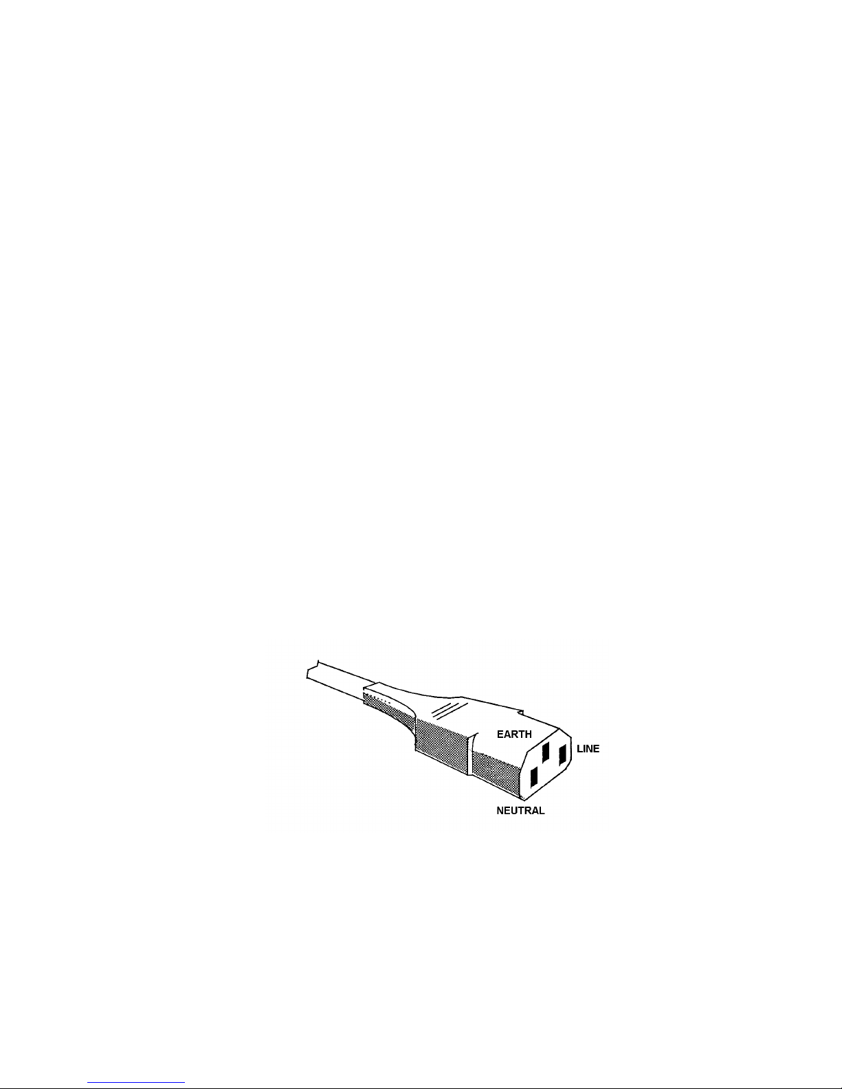
3. Connect the mains lead.
An ac supply cable, complete with a mating connector socket for the IEC plug on the
1250, is supplied. This cable should be connected to the user's ac supply in accordance
with the following colour code:
BROWN : LINE
BLUE : NEUTRAL
GREEN/YELLOW : EARTH
If the user already has available a supply cable terminated with an IEC socket, then this
can be plugged directly into ac supply plug on the 1250. It should be ensured. however,
that the socket is correctly wired, as shown in Fig. 2. 1.
Figure 2.1 - IEC power socket connections
4. Press the Power switch to On.
Page 27

1250 Frequency Response Analyzer Installation
CWB / 1250_Op / Issue 9A 2-5
2.4 ACCESSORIES
The 1250 accessories are supplied in a polythene bag packed with the instrument. The
accessory bag should contain:
a. 1 fuse, 1A SLO BLO, for 240V ac supply
b. 1 fuse. 2A SLO BLO, for 115V ac supply
c. 2 rack mounting brackets ("ears")
d. 1 slide mounting bar, part no. 12502024B, for telescopic slide rack mounting
e. 4 screws, M4 X 12 countersunk, to fix item d
f. 3 cable assemblies, terminated for front panel connections
An appropriate ac mains cable is packed with the instrument. If ordered with the 1250, a
telescopic rack slide mounting kit (Option 12505B, or 12505C for U.S.A.) is also packed.
2.5 RACK MOUNTING
The 1250 can be rack mounted in two ways: either by using fixed rails in the rack to
support the underside of the case, or by using telescopic slides to support the 1250 and
allow easy withdrawal for servicing.
With either method, the pair of rack mounting cars included in the accessory kit is
substituted for the finisher trims on the 1250; screws inserted through the ears and into
the rack keep the unit in place.
Note 1: The rack mounting ears must be used only to prevent the 1250 sliding out of the
rack. They are not designed to support the whole weight of the instrument.
Note 2: When the 1250 is rack mounted on telescopic slides, ensure that the rack will
not tip over when the slides are fully extended.
Two slide mounting kits are available as optional accessories:
1. kit 12505B (Accuride; UK), containing:
a. 1 telescopic slide kit, plus fixings
b. 14 screws, M4 X 6 panhead, to fix slide inner members to the mounting bars
c. 14 washers, M4 crinkle
d. 4 screws, M6 satin chrome, to fix front panel to rack
e. 4 washers. M6 plain
f. 4 caged nuts, M6, to fix front panel to rack
This kit is suitable only for 30 ins deep IMHOF IMRAK Series 80 or dimensionally similar
cabinets.
2. kit 12505C (Jonathan; USA), containing:
a. 1 replacement case top, part no. 12500241A
b. 1 replacement case bottom, part no. 12500242A
c. 4 feet, self-adhesive, to support pcb's inside item b
Jonathan slides and fixings are not supplied by Solartron.
Page 28
Installation 1250 Frequency Response Analyzer
2-6 CWB / 1250_Op / Issue 9A
2.5.1 RACK DIMENSIONS
The internal rack dimensions required for fitting the 1250 are:
610mm (24 ins) deep X 485mm (19 ins) wide for fixed rail mounting, and
760mm (30 ins) deep X 485mm (19 ins) wide for telescopic slide mounting (using either
kit)
2.5.2 VENTILATION
Ensure that the rack in which a 1250 is mounted has adequate ventilation, either by an
extractor fan or by having the rear of the rack open.
2.5.3 FITTING TELESCOPIC SLIDE MOUNTING KIT 12505B (ACCURIDE)
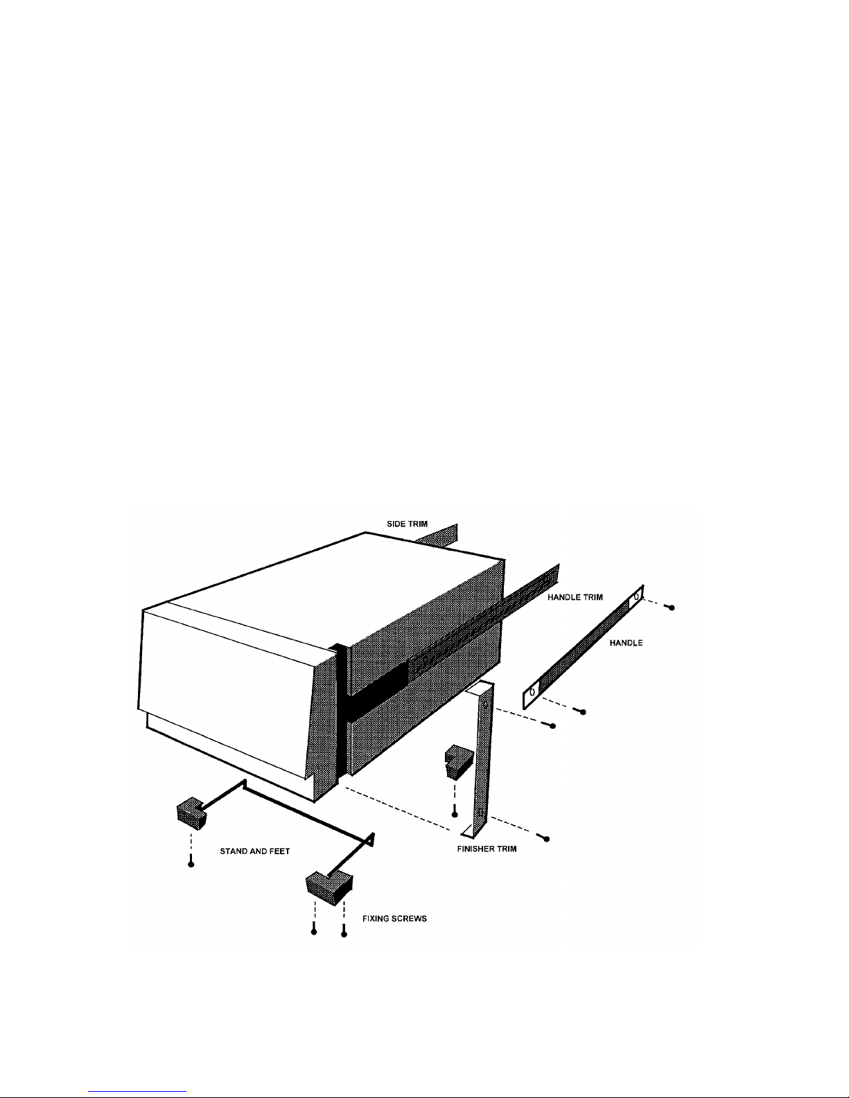
1. Remove the following items from the unit, as shown in Fig. 2.2:
a. Finisher Trim (two off)
Retain the four M4 x 16 panhead screws and M4 crinkle washers for securing the
rack ears.
b. Handle and Handle Trim
c. Side Trim
Located on the opposite side to the handle, it is normally secured by a pip on the
finisher trim, and slides out backwards.
d. Feet (four off) and Tilt Bar
The tilt bar is secured by the two front feet.
Figure 2.2 - Removal of trims, handle, feet, and tilt bar
Page 29

1250 Frequency Response Analyzer Installation
CWB / 1250_Op / Issue 9A 2-7
2. Fit the following items to the unit, as shown in Fig. 2.3:
a. Rack Ears (two off)
Fit the rack ears in place of the finisher trim, using the same fixings.
The ears may he fitted as illustrated, or with their flanges facing the rear of the
1250, which causes the unit to stand out further in the rack, allowing use of racks
too shallow for normal mounting.
b. Slide Mounting Bar
Screw the bar to the chassis in the former position of the handle, using the four
M4x12 csk screws provided. The bar fits correctly only one way round, with
threaded holes nearest the front.
The corresponding mounting bar on the left-hand side of the unit is supplied
already fitted behind the side trim (part no. 12502019B), it is slightly narrower than
the right-hand bar.
Figure 2.3 - Fitting rack ears and telescopic slide inner members
Page 30
Installation 1250 Frequency Response Analyzer
2-8 CWB / 1250_Op / Issue 9A
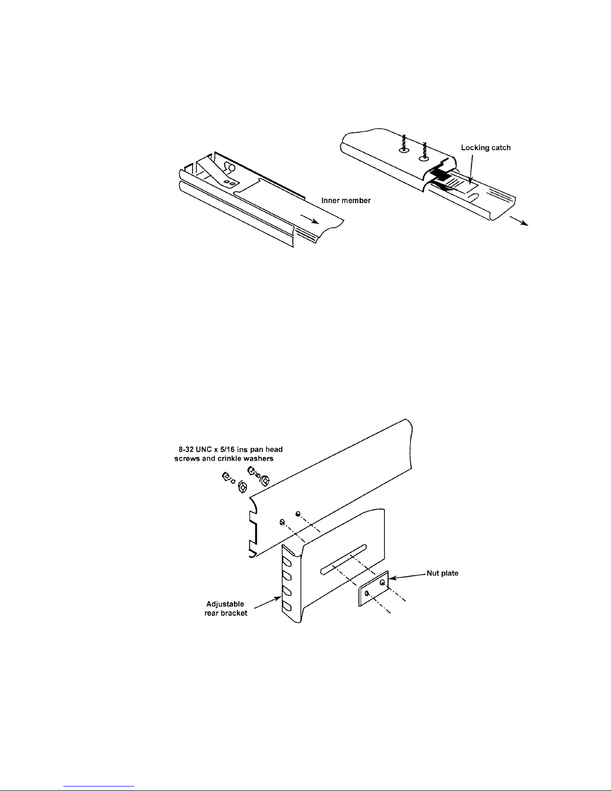
c. Telescopic Slide Inner Members (two off)
The telescopic slides are supplied with inner and outer members, slotted
together. Slide out the inner member as shown in Fig. 2.4. depressing the
locking catch at the halfway point.
Figure 2.4 - Separating the inner and outer slide members, prior to fixing
Screw the slide inner members to the mounting bars, using the fourteen M4X6
panhead screws supplied, seven each side.
3. Fit the following items to the telescopic slide outer members, as shown in Fig. 2.5
and 2.6:
c. Adjustable Rear Brackets (two off)
Fit one rear bracket to each outer member, but do not fully tighten the screws
until the 1250 is fitted into the rack (step 6).
Figure 2.5 - Fitting a rear bracket
Page 31
1250 Frequency Response Analyzer Installation
CWB / 1250_Op / Issue 9A 2-9
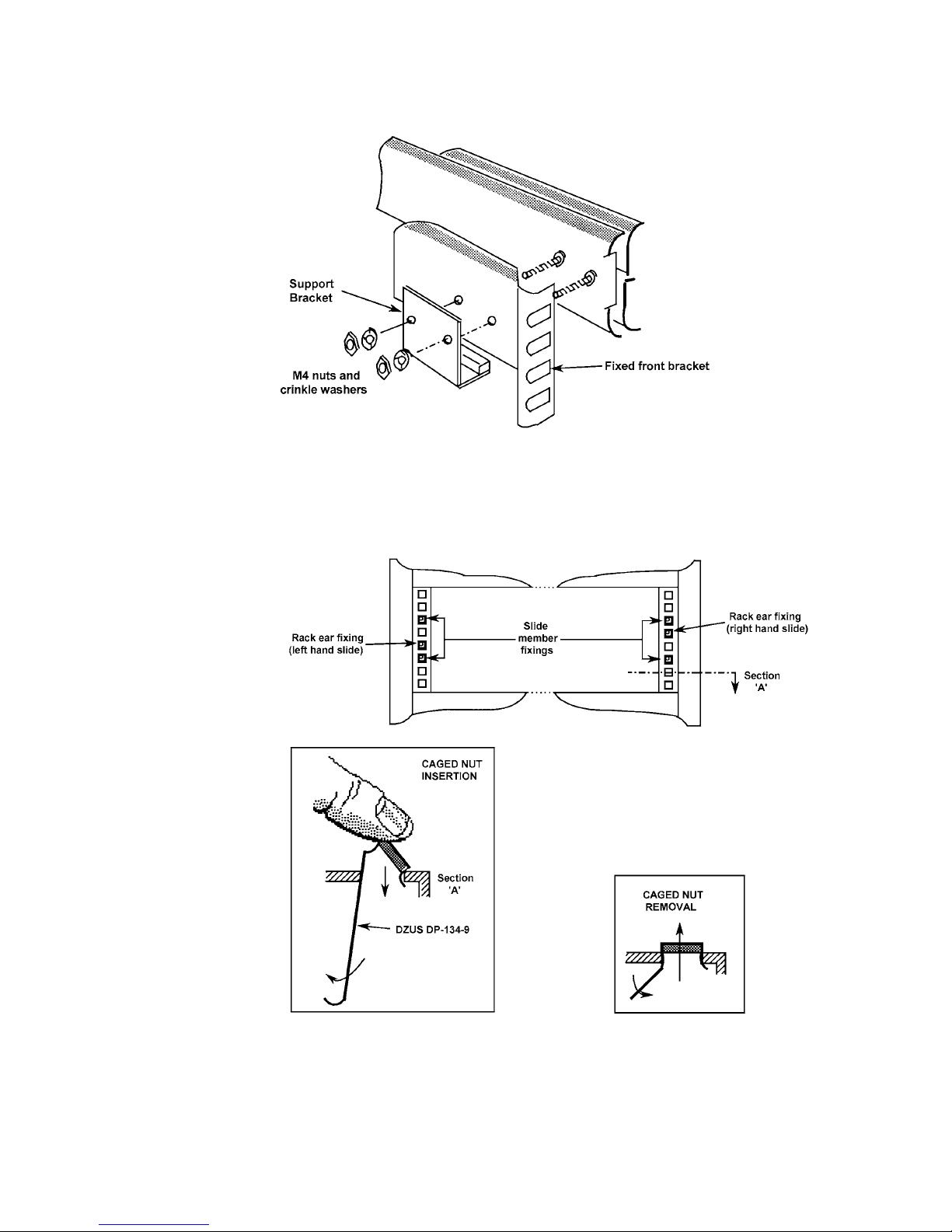
d. Fixed Front Brackets together with Support Brackets (two off each)
Figure 2.6 - Fitting a front bracket and support bracket
4. Fit the M6 caged nuts for outer slide member and rack ear fixing into the rack in
positions shown in Fig. 2.7. How to insert and remove caged nuts is shown in the
figure detail.
Figure 2.7 - Cage nut insertion in Imrak Series 80 (and similar) cabinets
Page 32
Installation 1250 Frequency Response Analyzer
2-10 CWB / 1250_Op / Issue 9A
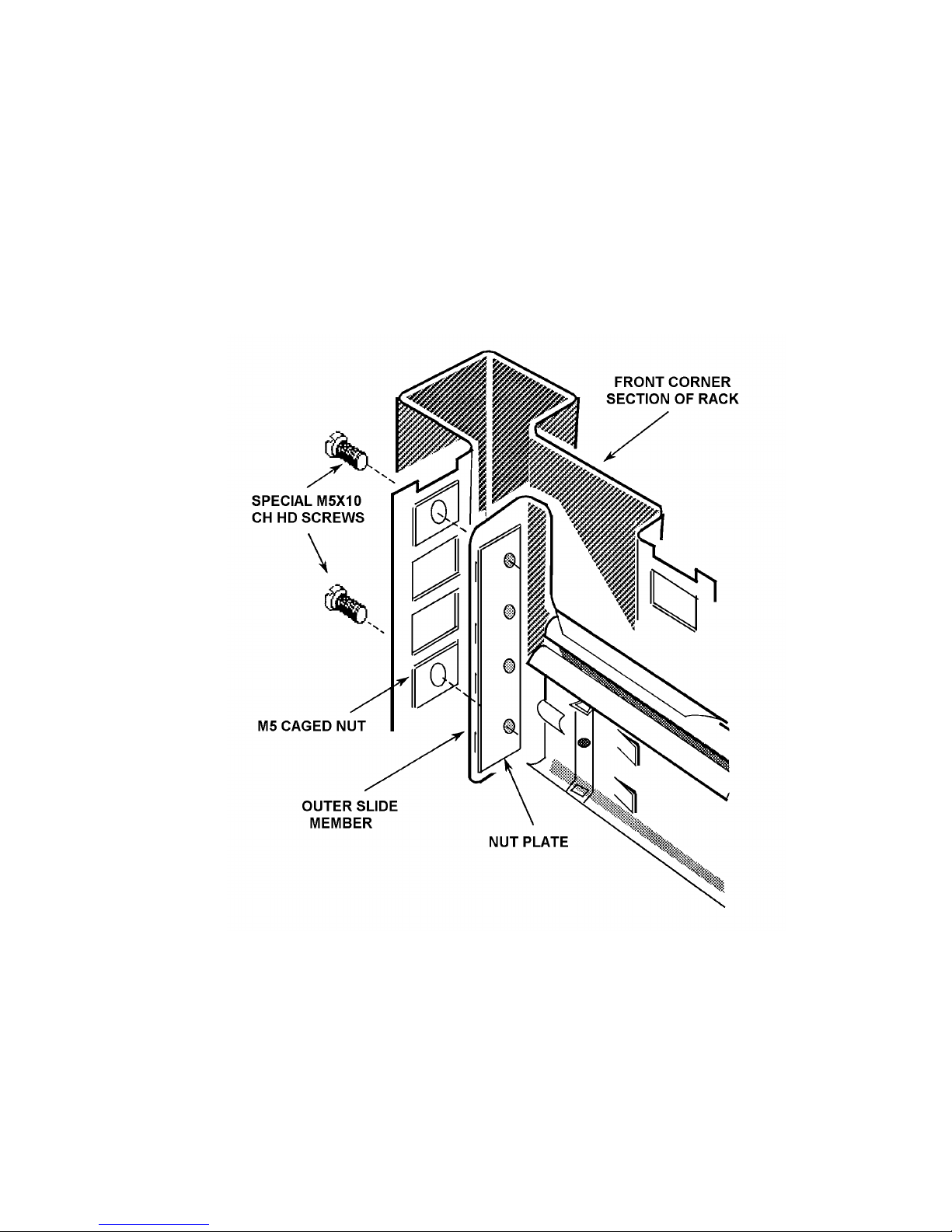
5. Fit the Outer Slide Members (two off) to the rack, as shown in Fig. 2.8
Note that the tapped holes in the nut plate are off centre to provide maximum
lateral adjustment. Fit the plates, as shown, with the holes offset towards the
rack exterior.
Fitting one end of an outer member is facilitated if the other end is supported,
by hooking the bracket at the other end over an M5 screw pushed into the top
caged nut.
Tighten the M5 screws securing each member until it is held moderately firmly
in the rack, approximately in the centre of its travel. The members must,
however, be free enough to take up any adjustment when the 1250 is first
fitted into the rack.
Figure 2.8 - Fitting the outer slide members into the rack
Page 33

1250 Frequency Response Analyzer Installation
CWB / 1250_Op / Issue 9A 2-11
6. Finally, fit the 1250 into the rack, as follows:
a. Offer the 1250 up to the rack and feed the inner telescopic slide members into the
outer members, pushing the unit into the rack until the locking catches engage
and lock.
b. Depress both catches and push the unit fully into the rack, ensuring that no cables
are trapped.
c. Tighten the screws on the outer slide members in the following order:
1. The M5 screws securing the rear bracket to the rack.
2. The M5 screws securing the front bracket to the rack.
3. The 8-32 UNC screws securing the rear bracket to the outer slide member.
2.5.4 FITTING TELESCOPIC SLIDE MOUNTING KIT 12505C (JONATHAN)
Remove the following items from the unit. as shown in Fig. 2.9:
a. Finisher Trim (two off)
Retain the four M4X16 panhead screws and M4 crinkle washers for securing the
rack ears.
b. Handle and Handle Trim
Figure 2.9 - Removal of trims, handle, top and bottom cases
Page 34

Installation 1250 Frequency Response Analyzer
2-12 CWB / 1250_Op / Issue 9A
c. Side Trim
Located on the opposite side to the handle, it is normally secured by a pip on the
finisher trim, and slides out backwards.
Check that the threaded bar supplied already fitted behind the side trim is part
no. 12502019B.
d. Case Top and Case Bottom
Retain the five screws and washers for securing the replacement cases.
2. Fit the Self-adhesive Feet (4 off) to the inside of the Replacement Case Bottom in
the positions corresponding to those in the original case bottom.
3. Fit the following items to the unit, as shown in Fig. 2.10 overleaf:
a. Rack Ears (2 off)
Fit the rack ears in place of the finisher trim, using the same fixings. The flanges
must face the rear of the 1250.
b. Slide Mounting Bar
Screw the bar to the chassis in the former position of the handle, using the four
M4x12 countersunk screws provided. The bar fits correctly only one way round,
with the threaded holes nearest the front.
c. Replacement Case Top and Case Bottom
Use the original five screws and washers.
Fit the Jonathan Telescopic Slide (not supplied), e.g. Tru-Glide 110QD-2, and mounting
brackets to the unit and fit it into the rack. See the Manufacturer's slide specification
sheets for details of the fixings, brackets and mounting accessories.
Page 35

1250 Frequency Response Analyzer Installation
CWB / 1250_Op / Issue 9A 2-13
Figure 2.10 - Fitting rack ears, slide mounting bar and replacement cases
Page 36

Installation 1250 Frequency Response Analyzer
2-14 CWB / 1250_Op / Issue 9A
Page 37

Switching On and Initialising 1250 Frequency Response Analyzer
3-1 AMK / 1250 / 3
3
Switching On and Initialising
Section Page
3.1 Switch On 3.2
3.2 Initialising 3.3
3.3 Resetting 3.4
Page 38

Switching On and Initialising 1250 Frequency Response Analyzer
3-2 AMK / 1250 / 3
3.1 SWITCH ON
The mains on/off switch is under the bottom left hand corner of the front panel. Press in
to switch on, press again to switch off.
When the instrument is switched on, the Display setting is set to [All] (see Chapter 12
Section 2) regardless of its original setting. Therefore when power is switched on the
display will always show one of the following two messages:
Figure 3.1 - Power-up Message a.
This signifies that the 1250 has correctly remembered the settings for the Generator
etc., from the last time it was used. Also, any Learnt programs are still available, and
readings stored in the File have not been corrupted. Therefore the instrument may
continue to be used as if it had not been switched off. (A fuller explanation of this
feature is given in Chapter 14 Section 4 Power Fail).
The Time display, in hours, minutes and seconds, shows time elapsed since the
instrument was switched on, starting from zero. The time-of day can be entered in this
display from the Front Panel or externally, see Chapter 14 Section 3 Time Display.
Figure 3.2 - Power-up Message b.
This signifies that errors have been detected in the previous 1250 settings. Therefore
the control circuitry has erased the contents of the parameter store and returned all
settings to their default state. The contents of the File and the Learnt Programs 1 to 9
will also be erased, but Learnt Programs 10 to 18 will not be erased even if the
keyswitch is in the Supervisor position.
The configuration of the printed circuit boards (pcbs) present is also checked and the
"initialised" message displayed if:
a. Any of the essential pcbs are missing:
b. Any pcbs have been fitted or removed during the "power-off" period, e.g. option
boards.
The TIME display is reset to zero, as in "POWER RESTORED".
Page 39

1250 Frequency Response Analyzer Switching On and Initialising
AMK / 1250 / 3 3-3
3.2 INITIALISING
The 1250 can remember its previous settings for at least 100 hours whilst switched off.
Therefore it is most likely that POWER RESTORED will be displayed when the
instrument is switched on again. If the next measurement to be made is similar to the
one preceding switch-off, the 1250 is already virtually set up, and will need only slight
adjustment.
However, if a markedly different type of measurement is to be made, it is advisable to
“erase" all existing settings to ensure that no unwanted facilities, e.g. Bias, are
inadvertently left active. This is achieved by initialising, which returns all controls to
the default state, and also erases the File plus all Learnt programs (Note: To erase
Learnt Programs 10 to 18 the keyswitch must be in the Supervisor position). The default
states are given in Chapter 8, Menu Summary.
To initialise press "self test" on the front panel. Five softkeys will be assigned as shown
in Fig. 3.3:
Figure 3.3
Press INIT. Initialisation takes about 14 seconds to complete in Supervisor mode, and
about 250ms in Normal mode, (see Chapter 1, Section 4: Keyswitch). When initialisation
is complete, the Display will be as shown in Fig. 3.4.
Figure 3.4
The 1250 is now in an identical state to that shown in Fig. 3.2, except that Learnt
Programs 10 to 18 will also have been erased if the keyswitch is in the Supervisor
position. Numerical values, e.g. Generator Amplitude, will read "not entered" on the
Display when interrogated, but are actually set to their default values. The TIME display
is set to zero.
Page 40

Switching On and Initialising 1250 Frequency Response Analyzer
3-4 AMK / 1250 / 3
3.3 RESETTING
To return all settings to the default state, without erasing the File and Learnt Programs,
press the RESET soft key instead of INIT.
When resetting is complete, the Display will be as shown in Fig. 3.5.
Figure 3.5
For details of other “self test” functions, see Chapter 14 Section 2 Self Test.
Page 41

4-1
4
Making Measurements:
The Generator
Section Page
4.1 Simple Measurements 4.2
4.2 Setting the Generator 4.2
4.2.1 Introduction 4.2
4.2.2 Setting the Generator Menu 4.2
4.2.3 Waveform 4.2
4.2.4 Frequency 4.3
4.2.5 Clear 4.4
4.2.6 Amplitude 4.4
4.2.7 Bias 4.4
4.2.8 Modulated Carrier 4.4
4.3 Checking Generator Settings: Using the Status Displays 4.4
4.4 Starting the Generator 4.5
4.4.1 Generator Start Key 4.5
4.4.2 Generator Waveform Starting Point 4.5
4.5 Stopping the Generator 4.5
4.5.1 Introduction 4.5
4.5.2 Generator Stop Key 4.5
4.5.3 Generator Stop @ Key 4.6
4.5.4 Applications of the Stop @ Key 4.6
4.5.5 Generator Overload Protection 4.7
Page 42
Making Measurements: The Generator 1250 Frequency Response Analyzer
4-2 AMK / 1250 / 4
4.1 SIMPLE MEASUREMENTS
As the 1250 is so versatile, very comprehensive measuring sequences can be set up.
Before attempting these however, it is recommended that the user acquire familiarity
with the basic controls by making a few simple measurements first. Refinements such
as Sweep, Recording of Data, Scaling of readings etc. can then be added as experience
is gained.
The simplest way to start is to initialise, then couple the Generator output directly to the
Analyser Channel 1 input. The Generator and Analyser Menus can now be set up for a
single-frequency measurement, and the resulting readings will be shown on the Display
in Cartesian form.
A summary of all menus is given in Chapter 8.
4.2 SETTING THE GENERATOR
4.2.1 INTRODUCTION
Setting up the Generator Menu is explained in detail in the following section. The other
Menus are set in similar fashion, the salient points being explained under the relevant
headings. For quick reference, all the Menus are listed together in Chapter 8.
The following sections describe the making of measurements by using only the Front
Panel controls. Remote programming is described in Chapter 13.
4.2.2 SETTING THE GENERATOR MENU
Press GENERATOR MENU. The five soft keys will be assigned functions as per Fig.
4.1:
Figure 4.1
4.2.3 WAVEFORM
For simplicity, start by establishing the required waveform. Press WAVEFORM: the
Display will change to the form shown in Fig. 4.2.
Figure 4.2
The word in the square brackets identifies the waveform currently commanded from the
Generator: [sine] is the default state, [square] and [triangle] are the alternatives. The
Page 43

1250 Frequency Response Analyzer Making Measurements: The Generator
AMK / 1250 / 4 4-3
square brackets signify that the user has a choice as to which word or symbol shall
appear between them. Successively operate the SELECT key until the chosen word
appears in the square brackets.
Press ENTER, the new command will not be accepted by the 1250 until ENTER is
pressed. The Display will revert to that shown in Fig. 4. 1.
To verify that the new command has been accepted, simply press WAVEFORM again.
If [square] has been entered the Display should now be as shown in Fig. 4.3.
Figure 4.3
4.2.4 FREQUENCY
Press FREQ. The Display should now resemble Fig. 4.4.
Figure 4.4
The top left-hand section, here labelled "Current Data", displays the current frequency,
represented by FREQ + xxx.xx Hz. If no frequency has been entered since an
initialisation, the Current Data section will show "not entered" although the value will in
fact have defaulted to 100Hz.
Key in the new frequency from the numeric key pad. The figures will appear after the
"+" sign between the round brackets, in the section labelled "New Data" in Fig. 4.4. The
flashing cursor indicates where the next character typed will be placed.
The maximum number of characters that can be displayed between the round brackets,
excluding any exponent entry (described later), is six, or five digits plus decimal point. If
further digits are typed, they do not displace those already displayed, and will usually be
ignored by the 1250 if they exceed the specified resolution.
The units of frequency, Hz in Fig. 4.4, appear in square brackets and can therefore be
altered by operating the SELECT key, the choices being mHz, Hz and kHz.
Alternatively, range may be expressed in exponent notation, by using the EXP key. The
1250 accepts exponents in the range 10-9 to 10+9, these being keyed in as E-9 to E+9,
the sign of the exponent being changed by the +/- key.
Page 44

Making Measurements: The Generator 1250 Frequency Response Analyzer
4-4 AMK / 1250 / 4
The exponent must always be expressed with respect to the units in the square
brackets.
Having set the required value plus units and/or exponent in the New Data section,
ENTER must be pressed for the change to be actioned. The Display will again revert to
that shown in Fig. 4.1. If FREQ is pressed again, the new frequency will now appear in
the Current Data section.
Note that the format may have been altered by the transition from New to Current Data
status, e.g. if 0.25 kHz is entered, this will appear as 250 Hz in the Current Data section.
4.2.5 CLEAR
If an error is made whilst keying information into the New Data section, pressing CLEAR
erases the contents of the round brackets. As with "Setting the Waveform", the contents
of the New Data section has no effect on the 1250 settings until ENTER has been
pressed.
4.2.6 AMPLITUDE
Press AMPL. The Display will be similar to Fig. 4.4 for frequency, but show AMPL, with
units of rms voltage. Key in the new amplitude as described for frequency and ENTER.
Note. The 1250N Generator source impedance is low, at approximately 1.5 Ω. So, for
low impedance loads, multiply the amplitude required by a scale factor to get the
amplitude you must program.
The scale factor = load impedance + 1.5
load impedance
4.2.7 BIAS
Press BIAS. The Display will be similar to Fig. 4.4 for frequency, but show BIAS, with
units of dc voltage. As bias can be of either polarity, select the one required by the +/key, set the required voltage and ENTER.
4.2.8 MODULATED CARRIER
This is available only when the optional Modulator/Demodulator Unit is fitted in the
1250. Connecting the Unit and the use of the MOD key are described in Chapter 15
"Options". The default state is "off”, so if no unit is fitted, the MOD key is not used.
If an attempt is made to enter any state other than "off" via the MOD key, when no Unit
is present, an Error Code Number will appear in the Display, accompanied by a warning
"beep". The Error Codes are listed in Chapter 11.
This completes the setting up of the basic Generator menu. The remaining facilities
accessible via the GENERATOR MENU key do not need setting up for simple
measurements and are described in later sections.
4.3 CHECKING GENERATOR SETTINGS: USING THE STATUS
DISPLAYS
To cheek that the Generator, or any other section of the 1250, has been set up correctly,
the user could step through all the Menus again. However, a better method is to use the
STATUS key, as described in Chapter 11.
Attention is also drawn to the Mini-Status Display, described in Chapter 7.
Page 45

1250 Frequency Response Analyzer Making Measurements: The Generator
AMK / 1250 / 4 4-5
4.4 STARTING THE GENERATOR
4.4.1 GENERATOR START KEY
As a general rule, when setting up a new measurement after initialisation, the Generator
should be the last item in the sequence to be started. The GENERATOR START key
thus becomes the Measurement Start control. By this means, all output devices such as
plotter, printer and computer can be enabled in advance; any scaling etc. can be set up
and sweep details entered. All these facilities are then held waiting, so that when the
Generator is finally started, everything begins at the same time, and no readings are
lost.
Bearing this in mind, the Generator can, in fact, be started at any time, by simply
pressing GENERATOR START. For simple measurements, it does not usually matter
which is `started` first, the Generator or the Analyzer, but both must be running for
readings to be taken.
4.4.2 GENERATOR WAVEFORM STARTING POINT
For most applications of single sinewave measuring techniques, the Generator
waveform starting point is not critical. The power-up reset that occurs when the 1250 is
switched on, and the initialising routine both ensure that the Generator waveform
commences at 0° the next time that START is pressed.
However, if the Generator has been left halted as the result of a 'stop' command of any
kind, the waveform may not start again from 0°. See Section 5 'Stopping the Generator'
for details.
4.5 STOPPING THE GENERATOR
4.5.1 INTRODUCTION
Apart from using a remote controller, the Generator can be stopped by:
1. Pressing GENERATOR STOP.
2. Connecting the HI and LO GENERATOR STOP INPUT sockets on the rear panel
to each other; or connecting the HI socket to 0V.
3. Using the STOP @ key, as explained in Section 5.3.
If methods 1 or 2 are used, the Generator waveform will remain at the level reached
when the command was actioned. If not initialised, or switched off then on again in the
interim, the next START command will cause the waveform to continue from wherever it
had stopped.
4.5.2 GENERATOR STOP KEY
Because of its immediate action, the GENERATOR STOP key can be used as a 'Panic
Switch' to stop the measurement if things seem to be getting out of control!
If it is essential to know the exact start point, and re-setting in any form is inconvenient,
use the STOP @ key, as explained in Section 5.3.
There is no need to stop the Generator before changing the settings of frequency,
amplitude etc.
Page 46

Making Measurements: The Generator 1250 Frequency Response Analyzer
4-6 AMK / 1250 / 4
4.5.3 GENERATOR STOP @ KEY
This control enables the Generator to be stopped at any of the four cardinal points
shown in Fig. 4.5. When the key is pressed, four soft keys will be assigned, one to each
Stop point.
Figure 4.5
When the required soft key is pressed, the next time that the Generator waveform
reaches the selected Stop point, it will halt there and stay until START is pressed again
(unless the 1250 is initialised, or switched on and off again in the meantime).
When START is operated again, the STOP @ command is cancelled, and the
Generator will continue running from the cardinal point at which it had been instructed to
stop.
4.5.4 APPLICATIONS OF THE STOP @ KEY
Apart from enabling the user to ensure that the Generator waveform always starts from
a known point, this control has several other applications in sine wave mode:
1. STOP @ 0° enables any offsets in the system under test to be adjusted to zero,
before testing commences.
2. If a large piece of machinery is being controlled by the Generator, e.g. a
hydraulic jack, this can be brought gently to rest by using STOP @ 0°, instead of
being stopped in some arbitrary position from which it abruptly returns to zero,
as could occur if GENERATOR STOP were used and then the equipment
switched off.
3. STOP @ 90° or 270° enable maximum amplitudes to be determined empirically,
see Chapter 9 'VARIABLE' Section 1.5 for a typical procedure.
Page 47

1250 Frequency Response Analyzer Making Measurements: The Generator
AMK / 1250 / 4 4-7
4.5.5 GENERATOR OVERLOAD PROTECTION
Accidental Short-Circuit
The Generator is protected against accidental short-circuiting of its HI and LO terminals.
The 1250N (low source impedance) uses feedback within the power amplifier to limit the
current to ∼300mA into a short-circuit. The 1250 relies on its higher source impedance
(50 Ω) to limit the current to a similar value. No error message is displayed.
Excessive External Voltage at Generator Terminals
If an external voltage of between ∼ ± 18V (∼ ±22V for 1250N) and ∼ ±30V is applied
across the Generator HI and LO terminals, Error 31 'Generator Overload' is displayed
and the output is held open-circuit until the overload is removed.
For overloads greater than ∼ ±30V the 1250 and 1250N behave differently.
1250. An S.C.R. clamp is triggered which short-circuits the Generator terminals via 33Ω
for ∼ 5ms before open-circuiting them and displaying Error 31. Remove the overload to
restore normal operation.
1250N. An S.C.R. clamp is triggered which short-circuits the Generator terminals. Then:
a) If the overloading source can supply more than ∼ 800mA, an internal protection fuse
blows which open-circuits the Generator output. Error 31 is displayed. Replace the fuse
to restore normal operation.
The fuse is an 800mA anti-surge, 20mm X 5mm cartridge type, Part No. 360106110 and
is located on Option 12506D (Board 16). To access, remove the heat sink (4 screws).
b) If the overloading source cannot supply more than ∼ 800mA, the fuse does not blow
and the Generator output remains short-circuited even after the overload is removed.
Error 31 is not displayed. Switch the 1250N 'off then 'on' to restore normal operation.
During the short-circuit, the Generator output is fully protected.
Page 48

AMK/1250/3 5-1
5
Making Measurements: The Analyzers
Section Page
5.1 Introduction 5.2
5.2 Setting the [ANALYZER COMMON] Menu 5.2
5.2.1 ∫ Time 5.2
5.2.2 Delay 5.3
5.2.3 Harmonic 5.3
5.2.4 Order 5.4
5.2.5 Auto ∫ 5.4
5.2.6 Applications of Auto Integration 5.4
5.3 Setting Individual Analyzers 5.6
5.3.1 Range 5.6
5.3.2 Demod 5.6
5.3.3 Coupling 5.6
5.3.4 Input 5.6
5.4 Measurement Start 5.7
5.5 Stopping the Analyzer; Stop and Break Keys 5.8
5.6 Changing Menus during Recycle 5.8
5.7 Measurement Start Point 5.8
5.7.1 Implementation of Delay 5.8
Page 49

Making Measurements: The Analyzers 1250 Frequency Response Analyzer
5-2 AMK/1250/3
5.1 INTRODUCTION
Having completed the Generator Menu, the Analyzers may now be set up. Channels 1
and 2 are connected to Analyzers 1 and 2 respectively. The numbering of any
additional Analyzers is explained in Chapter 16, The 1251 Multichannel Analyzer
System.
5.2 SETTING THE [ANALYZER COMMON] MENU
Press ANALYZER MENU. The Display will show [ANALYZER COMMON]. The term
'COMMON' indicates that the values entered here will apply to all the Analyzers in the
system. Five soft keys are assigned as described below.
5.2.1 ∫∫ TIME (where ∫ is the symbol for integration).
Enter the required numerical value here, plus the chosen units, i. e. time [sec] or cycles
[cyc]. If the signal to be analysed is noisy, the rms error in the readings due to the noise
tends to zero as the integration time is increased. Hence the longer the integration time
that can be tolerated, the closer the final reading will approach to the true value of the
wanted signal.
The integration time chosen usually has to be a compromise between speed of
measurement and acceptably small errors in the reading.
The ability of the Analyzers to reject unwanted frequencies, especially harmonics is
illustrated in Fig. 5.1
Figure 5.1
The curves indicate that one cycle of integration will give a reasonable reading where
the signal contains little random noise, but may have some harmonic distortion.
Page 50

1250 Frequency Response Analyzer Making Measurements: The Analyzers
AMK/1250/3 5-3
For measurements where the random noise level is high, however, the number of cycles
of integration needs to be increased to improve the signal to noise ratio.
The minimum values that can be set are 10 ms or 1 cycle of the fundamental frequency,
whichever is the longer, up to 655 Hz. Above this, the values are 10 ms or 61 cycles of
the fundamental frequency, whichever is the longer (61 periods at 655 Hz = 93 ms).
If a time value is entered, the 1250 automatically rounds this up to give an exact
number of cycles, or blocks of 61 cycles, according to frequency. Hence the user would
normally enter a time value only as an approximate setting.
If no entry is made after initialising, a default value will be assigned automatically,
depending upon the frequency of the Generator. This value will be as per the minima
specified above.
If the user enters an integration time of less than the period of 1 cycle of the Generator
frequency, the 1250 will not reject it, but will automatically set the relevant minimum
integration time for the frequency concerned.
When the Analyzer is set to measure the nth harmonic, over x cycles of integration, the
1250 always interprets this as meaning x cycles of the fundamental frequency, and not
the harmonic.
One technique for evaluating the effect of different integration times, once
measurements are being made, is to observe the scatter on the displayed readings, with
the Analyzer on RECYCLE. If the current integration time is too short to allow
observation of the readings, add in a delay, as explained under Section 2.2 'DELAY'. If
the scatter is due to noise, or other spurious components, increasing the ∫ TIME value
should cause a decrease in the scatter.
5.2.2 DELAY
This facility enables a time delay to be interposed between applying the Generator
waveform to the system under test and taking a reading.
Two applications of this are:
1. To allow the system under test to 'settle' after a change to the input stimulus, e.g.
after each change of frequency when performing a sweep.
2. To enable scatter on readings to be observed on the Display, when using only a short
∫ TIME value.
Note: The 1250 itself does not require any delay to allow it to settle. However, on
receipt of a command to start, either from the front panel or by remote control, it takes
approximately 10 ms to action the command.
As with ∫ TIME, the required delay is entered as a number, plus units of time or cycles,
but the 1250 converts all delays into time values. See Section 4 'Measurement Start' for
the implications of this. There is no minimum delay, and the default value is zero.
5.2.3 HARMONIC
The 1250 can be set to analyze the response of the system under test at any harmonic
of the fundamental up to the 16th, provided that the frequency of the harmonic does not
exceed 65.535 kHz. Enter the required harmonic number, between 1 and 16, in the
round brackets in the Display. The default value is 1, i.e. the fundamental frequency.
Page 51

Making Measurements: The Analyzers 1250 Frequency Response Analyzer
5-4 AMK/1250/3
5.2.4 ORDER
Using Order Analysis, the 1250 computes the response of the system under test at the
first 16 harmonics of the analysis frequency, all within a single measurement period.
This is effectively a 'fast' harmonic analysis, since in the normal harmonic mode only the
selected harmonic response is computed within one measurement period. However,
Order Analysis does not work with AUTO ∫, and cannot be used when the analysis
frequency is greater than 650 Hz (or 400 Hz when Synchronising).
If Harmonic Analysis has also been set up, Order Analysis computes the 16 harmonics
of the chosen harmonic, rather than of the fundamental (generator) frequency.
For example, if HARMONIC (10) has been selected, then Order Analysis computes the
10th, 20th, 30th ..... 150th, and 160th harmonics of the measurement frequency,
provided that HARMONIC (10) is less that 650 Hz (or 400 Hz when Synchronising).
Setting up ORDER (2), for example, then displays the second of the 16 values viz: the
20th harmonic.
The Order Analysis facility is particularly useful in conjunction with the Synchroniser
Unit, Option 12501 (see Chapter 15, Section 1 for further explanation).
Note: REFORMAT (accessed via the DATA OUTPUT menu) must be 'on' when the
ORDER facility is in use.
5.2.5 AUTO ∫∫
When a signal contains random noise or other spurious components, it may be difficult
to decide how long an integration is required in order to give a result with acceptably
small error. The crude approach of providing plenty of time may entail a test sequence
that is unnecessarily lengthy, particularly if a succession of signals cover a wide
dynamic range and thus require different integration times.
With auto-integration the measurement is continued until either the variation in the
running average result becomes sufficiently small or the maximum time allowed has
expired. Two levels of acceptable variation are available, chosen by integrating for a
'short' or 'long' time, the readings being averaged until the Standard Deviation falls
below the limits:
short: = ±10% of reading ± 0.01% of full scale;
long: = ±1.0% of reading ± 0.001% of full scale.
Students 't' test is applied to the Standard Deviation to ensure a 90% confidence level.
The maximum time that the user is prepared to allow should be entered using the ∫
TIME key. If the 1250 has just been initialised, and no new value is entered here, the
default value is automatically increased when AUTO ∫ is enabled, to the longer of 3
cycles or 1 second. This is now the minimum time that can be set, i.e. auto-integration
relies on at least 3 readings.
If the maximum integration time is reached before the measured deviation has fallen
below the selected limit, a reading will still be displayed, but with ERROR 82 flagged as
a warning that the specified confidence level has not necessarily been achieved.
5.2.6 APPLICATIONS OF AUTO INTEGRATION
Where more than one Analyser is being used, auto-integration could usefully be
assigned to the channel with the worst signal-to-noise ratio. Once the chosen Standard
Deviation limit has been achieved on this channel, the measurement will terminate. It is
now probable that the readings on the less noisy channels will have even smaller
Standard Deviations.
Page 52

1250 Frequency Response Analyzer Making Measurements: The Analyzers
AMK/1250/3 5-5
Auto-integration can also be used to reduce sweep time when the signal-to-noise ratio
varies widely across the swept spectrum. Consider the points plotted in Fig. 5.2.
Figure 5.2 - Plot of readings from a sweep measurement
Either side of the band marked "noise", a fairly clear curve is indicated, as represented
in Fig. 5.3. A short integration time will suffice here.
Figure 5.3 - Idealised curve from Fig. 5.2
As the scatter on the readings increases as shown towards the centre of Fig. 5.2, the
integration time must be lengthened until it is at a maximum where the wanted signal is
completely obscured by noise. This process will yield a plot which approaches the
idealised curve of Fig. 5.3.
If a fixed integration time is chosen, this must be long enough to cope with the noisiest
part of the signal. Hence it will be unnecessarily long where the signal is relatively
clean. Auto-integration solves this problem as illustrated by the following example.
Example
With fixed integration time. Suppose that this must be 10 seconds in the noisiest
region. If the sweep consists of 60 steps, the sweep time would therefore be
60 X 10 = 600 seconds = 10 minutes
Page 53

Making Measurements: The Analyzers 1250 Frequency Response Analyzer
5-6 AMK/1250/3
With auto-integration. Not all the steps in the sweep will need the full 10 seconds. A
typical simplified allocation could be:
20 points at 10 seconds each = 200 seconds
15 points at 5 seconds each = 75 seconds
25 points at 1 second each = 25 seconds
TOTAL 300 seconds = 5 minutes
i.e. half the previous time.
5.3 SETTING INDIVIDUAL ANALYZERS
Having completed the setting up of the common features of the Analyzers, the last
operation of the ENTER key should have left the Display showing [ANALYZER
COMMON). Successive operations of the SELECT key will call up the specific Analyzer
menus, each of which will assign four soft keys as follows:
5.3.1 RANGE
Pressing this key offers the user a choice of several fixed ranges from 30mV to 300V.
See the full Specification, Chapter 17 for details of these.
There is also an auto-ranging feature whereby the 1250 itself selects the range which
will produce an accurate result with the best possible resolution. Measurements start on
the most sensitive range and as soon as an overload is detected, the measurement is
terminated, the range is changed and the measurement restarted. This process
continues until the correct range has been found.
On termination of the measurement, the Analyzer automatically resets to the most
sensitive range, so if on Recycle, the auto-ranging process is repeated for every
measurement. The default state is auto-range.
5.3.2 DEMOD
This key is used only when the optional Modulator/Demodulator Unit is fitted.
Instructions for its use will be found in Chapter 15, Options. The default state is off. The
Unit is not required for simple measurements.
If an attempt is made to enter any state other than off via the DEMOD key, when no
Unit is present, an Error Code Number will appear in the Display, accompanied by a
warning "beep". The Error Codes are listed in Chapter 11.
5.3.3 COUPLING
The default state gives direct [dc] coupling of the signal to the Analyzer input. This
mode should be used wherever possible, as it introduces minimum phase shift,
particularly at low frequencies.
On the other hand, if the incoming signal has an unwanted direct component, such as dc
bias, this could necessitate using the Analyzer on a relatively insensitive range, which
would impair the resolution of the ac component. In this case, ac coupling may he used
to block the dc component.
5.3.4 INPUT
On 1250A, 1250N, the Analyzer input can be routed via the 4mm sockets on either the
front or rear; this is selectable via the front panel or a remote command code. The
default is Front. For 1250B and 1250E, the inputs are hard-wired to the rear panel
sockets, and are unaffected by the front panel setting or remote commands.
Page 54

1250 Frequency Response Analyzer Making Measurements: The Analyzers
AMK/1250/3 5-7
5.4 MEASUREMENT START
The Generator and Analyzer are assumed to have been fully set up for making simple
measurements, as described in the previous sections.
As explained under 'Starting the Generator', it is recommended that the Analyzer be
enabled now, before the Generator is started. However, the user may choose either of
the following methods:
1. With the Generator stopped
a. Enable the Analyser by pressing either SINGLE if only one reading is to be
taken, or RECYCLE if a continuous series of readings is required. The Analyzer
Status will change from ANALYZER STOP to ANALYZER IDLE, i.e. the
Analyser is now ready to make a measurement, but cannot do so until the
Generator has started.
b. Press GENERATOR START. The Display will now be updated to show the
latest reading, and the Generator Status will change from STOP to RUN.
c. If the Analyser is on RECYCLE, its Status will change to RUN, but if a Delay has
been entered, the Status will alternate between DELAY and RUN.
If the Analyser is on SINGLE with a Delay, the Status will first show DELAY,
change to RUN whilst the measurement is being made, then revert to STOP on
completion.
2. With the Generator already running
a. Enable the Analyser by pressing either SINGLE if only one reading is to be
taken, or RECYCLE if a continuous series of readings is required. The Display
will be updated to show the latest reading.
b. The Status information will follow the sequence given in 1c.
The Running Display
When the 1250 has completed a measurement, the Display will resemble Fig. 5.4.
Figure 5.4 - The Running Display
The top left-hand number shows the frequency at which the measurement was made, in
this case 504 Hz. The remaining two numbers show the result of the measurement, in
Cartesian convention. Changing the Display to show readings in Polar or Log Polar
form is explained in Chapter 7.
Page 55

Making Measurements: The Analyzers 1250 Frequency Response Analyzer
5-8 AMK/1250/3
If taking single measurements, the Running Display will he updated once for each
operation of the ANALYZER SINGLE key. With ANALYZER RECYCLE commanded,
the Display is automatically updated as each measurement is completed.
The message in square brackets is the Mini Status Display and is explained in Chapter
7, Section 4.
5.5 STOPPING THE ANALYSER; STOP AND BREAK KEYS
When the Analyzer is on RECYCLE, it is normally stopped by pressing the ANALYZER
STOP key. The measurement then terminates when the current integration is complete.
This may take an unacceptably long time at very low frequencies, so if an immediate
stop is required, irrespective of validity of reading, press the BREAK key.
Also, if the Analyzer Status shows WAIT, this means that the Analyzer is waiting for
another section of the 1250 to complete its task. Pressing BREAK over-rides this and
returns control of the Analyzer to the Front Panel immediately. (Additional functions of
the BREAK key, which affect other sections of the instrument, are described in Chapter
14 Section 1 'The BREAK key').
5.6 CHANGING MENUS DURING RECYCLE
The Generator and Analyzer do not have to be stopped in order to change the Menus.
Any change that is entered will be held until the 1250 has completed the current
measurement. The alteration will then be implemented and the next measurement made
according to the new setting.
5.7 MEASUREMENT START POINT
The Analyzer must make its measurement with respect to some reference point on the
Generator waveform, known as the measurement start point. This start point varies
according to Generator frequency. At mid-frequencies, start will occur at the next 0°
crossing. At 4 Hz and below this could take an excessive time, so the period of one
cycle is divided into 104 equal parts, start occurring at the next 104th point. For
frequencies of approximately 655 Hz and above, integration occurs over blocks of 61
cycles, so start coincides with the beginning of the next 61-cycle block.
5.7.1 IMPLEMENTATION OF DELAY
As mentioned in Section 2.2, any Delay value entered is converted into a time period.
After this Delay time has elapsed, measurement commences at the next start point, as
defined above.
Page 56

6-1 CHFR/1250/2
6
The Sweep Facility
Section Page
6.1 Introduction 6.2
6.2 Logarithmic Sweep 6.2
6.3 Linear Sweep 6.2
6.4 Setting Up a Logarithmic or Linear Sweep 6.3
6.5 Executing the Sweep 6.3
6.6 Automatic Sweep Time 6.3
6.7 End of Sweep Conditions 6.4
6.8 Further Sweeps 6.4
6.9 Stopping and Re-starting the Sweep 6.4
6.9.1 Introduction 6.4
6.9.2 Commands Which Produce “Sweep Stop” Status 6.4
6.9.3 Commands Which Produce “Sweep Idle” or “Hold” Status 6.5
6.10 Changing Parameters in Mid-Sweep 6.5
6.11 Harmonic Sweep 6.5
6.11.1 Introduction 6.5
6.11.2 Perfoming a harmonic Sweep 6.6
6.11.3 Error 21 6.6
6.11.4 Sweep Termination Conditions 6.6
Page 57

The Sweep Facility 1250 Frequency Response Analyzer
6-2 CHFR/1250/2
6.1 INTRODUCTION
The setting up of single frequencies has already been described in the Generator Menu
Section. However, the 1250 can also carry out an automatic sweep from one
preselected frequency to another. This can be performed in either direction, using
logarithmic or linear increments.
The sweep can be selected to cover the entire frequency range from 10 µHz to
65.5 kHz, or any part of it.
A special form of Harmonic Sweep can also be performed, as described separately.
6.2 LOGARITHMIC SWEEP
The 1250 offers four ways of setting a logarithmic sweep, selected by soft keys. In each
case, the successive steps in Generator frequency are related by constant ratios,
defined as follows.
1. By n steps per decade. The ratio is the nth root of 10. Hence the frequencies appear
spaced at equal intervals if plotted along a logarithmic base line. See example, Fig.
6.1.
Figure 6.1 - Example of Logarithmic Sweep at 4 Steps per Decade
2. By n steps per octave. The ratio is the nth root of 2.
3. By n steps in the whole sweep. The ratio of ƒ
MAX
to ƒ
MIN
is calculated, let this be R.
The step ratio is then the nth root of R.
4. By the ratio of the new frequency to the previous one. Here the user can enter the
actual ratio required as a number, e.g. if each frequency is to be √2 times the
previous one, enter 1.414 under ratio.
6.3 LINEAR SWEEP
There are two ways of setting a linear sweep:
1. By n Hz per step, where the Generator frequency is altered by a constant number of
Hz per step throughout the sweep.
2. By n steps in the whole sweep. Here ƒ
MIN
is subtracted from ƒ
MAX,
the difference is
divided by n, and the result added to, or subtracted from, the previous frequency for
each step.
Page 58

1250 Frequency Response Analyzer The Sweep Facility
CHFR/1250/2 6-3
6.4 SETTING UP A LOGARITHMIC OR LINEAR SWEEP
1. Press the Generator, Analyzer and Sweep STOP keys.
2. Use the Generator Menu to set the required amplitude, bias, waveform etc. The
Generator frequency need not be altered, as the Sweep controls will over-ride any
existing setting.
3 . Set up the Analyzer Menus.
4. Press SWEEP MENU; four soft keys will be allocated as follows:
FR MIN Enter the required minimum frequency here.
FR MAX Enter the required maximum frequency here.
∆LOG Enter the required number of steps, followed by the chosen log sweep.
∆LIN Enter the required number of steps, followed by the chosen linear
sweep.
5. Press the START/CONTINUE key. Five soft keys will be allocated. The first soft
key, HARMONIC is explained in Section 11. The remaining four keys act in pairs,
one pair for log sweeps and one pair for linear. Each pair controls the direction of its
associated sweep, either upwards or downwards as indicated by the arrows.
Press the key which shows the required direction for the type of sweep selected.
The Sweep Status will change from STOP to IDLE, and also show the type of Sweep
selected, e.g. log up.
6. Press ANALYZER SINGLE if the steps of the sweep are to be executed manually, or
ANALYSER RECYCLE if it is desired to carry out the whole sweep automatically.
The Analyzer Status will change to IDLE.
6.5 EXECUTING THE SWEEP
Press GENERATOR START. The sweep will now commence. If an ↑ key has been
selected, the Generator will first be set to FR MIN and the Analyzer will take a reading at
this frequency. Conversely, if a ↓ key is operative, the first reading will be at FR MAX.
On ANALYZER SINGLE, only this one reading will be taken. To continue the sweep,
successively operate the SINGLE key to step the Generator through the defined range,
with a reading taken at each frequency until the opposite limit is reached.
On ANALYZER RECYCLE, readings are taken automatically, one per step of the
Generator frequency, until the sweep is complete.
6.6 AUTOMATIC SWEEP TIME
With automatic sweeps, only one measurement is made at each frequency. As each
measurement finishes, an "integration complete" signal allows the Generator to step on
to the next frequency. Account is also taken of any Delay that has been entered.
Hence, the time taken to complete an automatic sweep is dependent not only upon the
start and finish frequencies and the number of steps in between, but also on any Delays
programmed and the Integration Time chosen.
Page 59

The Sweep Facility 1250 Frequency Response Analyzer
6-4 CHFR/1250/2
6.7 END OF SWEEP CONDITIONS
On the completion of a sweep, the Status of the Analyzers and Sweep controls will have
reverted to STOP, but the Generator will keep running at the last frequency
commanded.
6.8 FURTHER SWEEPS
To repeat the sweep described in Sections 4 and 5 above, the same procedure could be
repeated. A simpler way to repeat, or reverse, an already set-up sweep is to:
a. Press SWEEP START/CONTINUE, followed by the relevant soft key, as
explained in Section 4 step 5.
b. Press ANALYZER SINGLE or RECYCLE as before, but in this case, as the
Generator is already running, the Analyzer key now acts as the Sweep Start
Control.
To carry out further sweeps, using markedly different settings, it is advisable to repeat
Sections 4 and 5 sequence entirely.
6.9 STOPPING AND RE-STARTING THE SWEEP
6.9.1 INTRODUCTION
There are several ways of stopping a sweep, which can be grouped in two main
categories:
a. Those which produce the SWEEP STOP status. The sweep cannot now be
continued from the frequency at which it stopped but reverts to the relevant start
frequency and begins again from there. The START/CONTINUE key is used to
re-start the sweep.
b. Those which produce the SWEEP IDLE or HOLD status. The sweep can be
continued from the frequency at which it stopped. The sweep parameters can
also be changed before continuing.
6.9.2 COMMANDS WHICH PRODUCE "SWEEP STOP" STATUS
a. SWEEP STOP. The Analyzers will complete the reading at the current
Generator frequency, then continue to take readings at this frequency on
RECYCLE.
b. BREAK. The Generator continues running at the current frequency, but the
Analyzers and Sweep stop immediately. The Display will continue to show the
last reading taken before BREAK was pressed.
c. INIT. Whilst this command produces the SWEEP STOP condition, it also
returns all other settings to their default values, as described in Chapter 3.
d. RESET. As for INIT, but Learnt Programs and Files are not cleared.
e. Note that a normal continuous sweep, i.e. one where the Analyzers are set to
RECYCLE, stops automatically after taking a reading at the terminating
frequency. This also sets the SWEEP STOP status.
Page 60

1250 Frequency Response Analyzer The Sweep Facility
CHFR/1250/2 6-5
6.9.3 COMMANDS WHICH PRODUCE "SWEEP IDLE” OR "HOLD" STATUS
a. ANALYZER SINGLE. The Analyzers will complete the current measurement, display
a valid reading and stop. If SINGLE is pressed again, the Generator will step on to
the next frequency in the sweep, and a new measurement will be made. This
process may be continued until the sweep is complete.
Alternatively, if ANALYZER RECYCLE is pressed again, the sweep will continue
automatically. An application of this technique is given in Section 10.
b. SWEEP HOLD. The Analyzers will complete the current measurement, and display a
valid reading. Unlike method "a", however, the Analyzers will continue measuring
the signal, and the reading is continuously updated. This enables the user to make
fine adjustments to the Generator settings, whilst observing their effect on the
reading. See also Section 10 for other applications.
c. ANALYSER STOP. This command would not normally be used if all the sweep
readings are required. When given, the Analyzers complete the current cycle of
integration and display a reading, which may be accompanied by the message
ERROR 89. This implies that the reading is not valid.
The sweep can be restarted by pressing either ANALYZER RECYCLE or SINGLE.
d. GENERATOR STOP. This command will stop the sweep, but the current
measurement will not give a reading. To restart the sweep, press GENERATOR
START. The Analyzers will attempt to complete the measurement which was
interrupted by the STOP command, but the reading will be invalid. All further
measurements will be made correctly.
6.10 CHANGING PARAMETERS IN MID-SWEEP
When the sweep has been halted, preferably by either pressing SWEEP HOLD or
ANALYZER SINGLE, the user can change the settings and then continue. For example,
if the steps of the sweep are too coarse to permit detailed observation of a steep-sided
response curve, the sweep can be temporarily stopped somewhere near the area of
interest. The frequency increments can now be made smaller, logarithmic sweep
changed to linear, direction of sweep reversed etc., then the sweep continued.
If SWEEP HOLD is used, so that the Analyzers are continuously updating the displayed
reading, the VARIABLE key can be pressed, thus permitting extremely fine adjustments
to be made to the Generator settings, as described in Chapter 9.
6.11 HARMONIC SWEEP
6.11.1 INTRODUCTION
For this type of sweep, the Generator is left set to the required fundamental frequency.
The Analyzers then sweep through to measure the response at all the harmonics up to
the 16th (provided that this does not exceed the maximum frequency of the instrument).
The SWEEP MENU soft key settings are ignored in this mode.
Page 61

The Sweep Facility 1250 Frequency Response Analyzer
6-6 CHFR/1250/2
6.11.2 PERFORMING A HARMONIC SWEEP
1. STOP the Generator, Analyzer and Sweep.
2. Use the GENERATOR MENU keys to set the required fundamental frequency.
3. Set up the Analyzer Menu. Any Harmonic number entered, other than 1, will be
over-ridden by the Harmonic Sweep command.
4. Press SWEEP START/CONTINUE to obtain the soft key titles. The Sweep Status
will remain at STOP.
5. Press the HARMONIC soft key. The Sweep Status will change to IDLE, i.e. ready to
start.
6. Press ANALYZER RECYCLE if all 16 harmonics are to be scanned as the result of
one command, or ANALYZER SINGLE if the measurement at each harmonic is to be
initiated manually.
7. Press GENERATOR START. If RECYCLE has been enabled, the complete sweep
will now be carried out.
If SINGLE has been enabled, the Display will now change to show the result of the
measurement at the fundamental frequency.
Each time the SINGLE key is pressed, a new reading will be displayed, showing the
response at each successive harmonic frequency.
6.11.3 ERROR 21
If ERROR 21 is displayed, the limit of 65 kHz has been reached before completion of
sweep.
6.11.4 SWEEP TERMINATION CONDITIONS
If, on ANALYZER RECYCLE, the sweep is completed normally, or is terminated due to
the Error 21 condition, the Analyzers will be left set to Harmonic 1, i.e. the fundamental
frequency. However, if the sweep is not completed, e.g. is stopped by pressing SWEEP
STOP or SWEEP HOLD, or is only stepped part way through by using ANALYZER
SINGLE, the Analyzers will be left set to the last harmonic measured.
If the latter condition is not required, the Analyzers can be returned to the Harmonic 1
state by entering a "1" in the [ANALYZER COMMON] Menu in the HARMONIC position.
INITialising and RESETting have the same effect, but also return all the other
parameters to their default values.
Page 62

CHFR/1250/2 7-1
7
The Display Menu and Mini Status
Section Page
7.1 Introduction 7.2
7.2 Sources 7.3
7.3 Co-Ordinates 7.3
7.4 Mini Status Display 7.4
Page 63
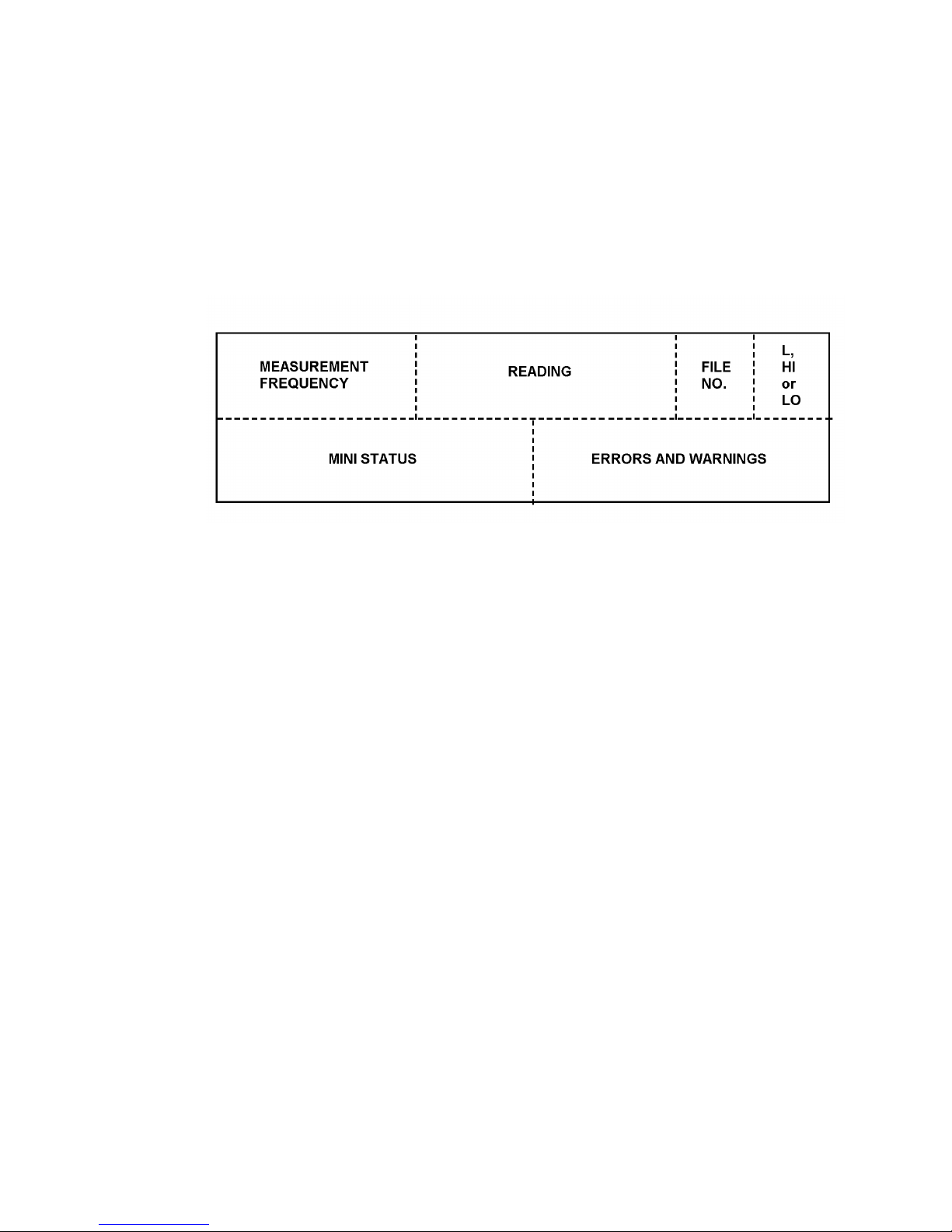
The Display Menu and Mini Status 1250 Frequency Response Analyzer
7-2 CHFR/1250/2
7.1 INTRODUCTION
In the default state the Display uses Channel 1 Analyzer as its source, and presents the
readings in cartesian (a+jb) form. By using the DISPLAY/PLOTTER MENU key, in
conjunction with its associated soft keys, different sources and co-ordinates can be
selected.
Display Areas
Specific areas of the display are allocated to particular types of message, as shown in
Figure 7.1.
Figure 7.1 - Allocation of Display Areas
Measurement Frequency
This is the frequency at which the measurement was made, which, in the case of a
harmonic of order measurement, is not necessarily the same as the Generator
frequency.
Reading
This is the result of the measurement; the user may choose the co-ordinates as listed in
section 3.
File number
This area is blank unless data is being viewed from the File, in which case a number
from 1 to 470 will be displayed. This number indicates the relevant line in the File, as
explained in Chapter 12.
Limit High or Low
This area is blank unless limits have been applied to the readings by using the
FUNCTION key, as described in Chapter 10.
Mini status
This is explained in section 4.
Note: when no data is output to the Display (Chapter 12 Section 1.2) no mini status
messages will appear in this area.
Errors and Warnings
A list of these, with explanations is given in Chapter 11, Section 2.
Note: when no data is output to the Display (Chapter 12 Section 1.2) no errors or
warnings will appear in this area.
Page 64

1250 Frequency Response Analyzer The Display Menu and Mini Status
CHFR/1250/2 7-3
7.2 SOURCES
With two Analyzers in use, they may be employed as two separate measuring systems,
called Channel 1 and Channel 2. Establish the required Channel [Ch 1] or [Ch 2] as
source, by using the SELECT and ENTER keys in the usual way.
These two Channels can also be used together for point-to-point measurements, by
selecting [Ch 2/Ch 1]. In this case, Channel 1 would be connected to monitor the input
to the system under test, and Channel 2 to the output.
If more than two Analyzers are available, the other Channels are established by
selecting [Ch ( )] and entering the required Channel number in the round brackets. To
avoid confusion, the user should not enter a 1 or a 2 here. If the 1250 sees a 1 or a 2 in
the round brackets, it automatically selects Channel 1 or Channel 2 respectively, and the
STATUS display will show Ch 01 or Ch 02 as the chosen Source.
However, if [Ch ( )] is selected again, the round brackets will be empty, whereas if, for
example, Channel 11 had been established, the Display would show [Ch (11)].
The remaining mode is [Ch ( )/Ch m]. Using this, the ratio of any two Channels can be
displayed, for example by setting Channel 1/Channel 2, the reciprocal of the point-topoint measurement described above can be calculated.
To set this up, type 1 on the key pad and enter it. TheDisplay will now show [Chl/Ch( )].
Now enter 2; the Display will revert to [DISPLAY] MENU but if the SOURCE soft key is
pressed again, the Display will show [Ch (1)/Ch 2]. STATUS will show Ch 01/02.
To avoid confusion, the user is advised not to enter the specially-allocated Ch 2/Ch 1
mode here. If this is done, the 1250 will correctly establish the required sources, and
STATUS will show Ch 02/01. However, the originally selected source title will be unnumbered, i.e. show [Ch ( )/Ch m].
Either of the dual-channel modes can be used for measuring the forward gain of a
closed loop system, which might become unstable if the feedback loop were broken. It
is a straightforward matter to measure the error signal at the same time as the output.
7.3 CO-ORDINATES
In addition to Cartesian, the other co-ordinate presentations available are:
1. Polar, which is displayed as r, θ
where r = √ (a2 + b2) and θ = arctan b/a.
2. log Polar, which is displayed as log r, θ.
Where θ = arctan b/a as before, and log r is defined as follows.
a. For Single Channel measurements, log r represents:
20 log
10 √
(a2 + b2) in dB relative to 1V.
By using an appropriate scaling factor, the units can be changed to dB relative to any
reference voltage.
b. For Dual Channel measurements, log r represents the ratio of the two readings in dB,
e.g. for Ch 2/Ch 1:
log r represents 20 log
10
√ (a2 2 + b2 2)
dB
√ (a1 2 + b1 2)
Page 65

The Display Menu and Mini Status 1250 Frequency Response Analyzer
7-4 CHFR/1250/2
7.4 MINI STATUS DISPLAY
When the bottom line of the Display appears in square brackets, as Fig. 7.2 below, the
SELECT key can be used to call up the following status messages. Where one of
several different messages may follow a title, they are shown in the form:
/IDLE/RUN/NONE.
Figure 7.2 - Example of Mini Status Display showing TIME
[FRA READY]/BUSY/PROGRAM/remote/pause
[TIME xx:xx:xx]
[GENERATOR RUN]/STOP/FAULT
[ANALYZERS STOP]/RUN/IDLE/DELAY/WAIT
[SWEEP STOP]/IDLE/HOLD/RUN
[PLOTTER STOP]/IDLE/RUN/NONE
[SYNC. NONEI/IDLE/WAIT/STABLE/LOCKED/FAULT (but without the fault
identification number which appears when the STATUS key is used).
[GPIB IDLE]/maj TACS/maj LACS/min TACS/min LACS.
[STATUS xxxxxxxx] The significance of the 8-digit nurnber is explained in Chapter 13,
Section 3.1.
Page 66

AMK/1250/1 8-1
8
Menu Summary
Section Page
8.1 Introduction 8.2
Page 67

Menu Summary 1250 Frequency Response Analyzer
8-2 AMK/1250/1
8.1 MENU SUMMARY
The table below is a summary of all 1250 menus.
Notes:
a. Italics denote default values.
b. Round brackets denote that a numerical entry is required, which may be up to 5 digits plus
decimal point, and exponent, unless an integer is indicated in the table.
c. Limits are shown for each numerical entry, e.g. the range of frequency that can be entered
via the FREQ soft key is 1E-5 to 65535 Hz, as shown in the table.
d. If just initialised, the 1250 displays "not entered" in front of the round brackets; otherwise
the last ENTERed value is displayed. When "not entered" appears, the default value is
operative.
e. Square brackets denote choice via the SELECT key.
f. All voltages are expressed as rms values.
Page 68

1250 Frequency Response Analyzer Menu Summary
AMK/1250/1 8-3
1250 MENU SUMMARY
MENU SELECTION SOFT KEYS
GENERATOR [GENERATOR]
FREQ
(100 Hz)
1E-5 to
65535 Hz
AMPL
(0 V)
0 to
10.23V* =
BIAS
(0 V)
-10.23 to
+10.23 V
WAVEFORM
[ sine ]
[square ]
[triangle]
MOD
[ off ]
[carrier 1 on]
[carrier 2 on]
SYNCHRONISER
LEVEL
(0 V)
-5.1 to
+5.1 V
COUPLING
[DC]
[AC]
SLOPE
[ + ]
[ - ]
RATIO
(0 = off)
0 to 100
SYNCH
[ off ]
[ tight lock ]
[ loose lock]
[AMPL.
COMPRESS]
SOURCE
[Ch 1]
[Ch 2]
VALUE
(0 V)
1E-4 to
300 V
ERROR
(0 %)
1 to 50%
LIMIT
(0 V = off)
10mV to
10.23 V =
COMPRESS
[off]
[on]
[AUX.
AMPL BIAS WAVEFORM
GENERATOR] (Values as for [GENERATOR])
GENERATOR
STOP @
-
0°° 90°° 180°° 270°°
ANALYZER [ANALYZER
COMMON]
∫∫ TIME
( )**
0.01 to 1E5s
DISPLAY
(0 s)
0 to 1E5s
HARMONIC
(1)
1 to 16
integer
ORDER
(1)
1 to 16
integer
AUTO ∫∫
[ off ]
[ long ∫ on Ch 1 ]
[ long ∫ on Ch 2 ]
[short ∫ on Ch 1]
[short ∫ on Ch 2]
[ANALYZER 1]
or
[ANALYZER 2]
RANGE
[auto]
30mV to
300V in
decades
DEMOD
[ off ]
[carrier 1 on]
[carrier 2 on]
COUPLING
[DC]
[AC]
INPUT
[front] #
[rear]
[ANALYZER ( )]***
RANGE DEMOD COUPLING
(Values as for [ANALYZER 1])
SWEEP -
FR MIN
(0 Hz)
1E-5 to
65535 Hz
FR MAX
(0 Hz)
1E-5 to
65535 Hz
∆∆ LOG
(0 st/dec)
0.33 to 1E5
st/dec
0.1 to 33333
st/oct
1 to 1E5
st/swp
1.00001 to
1E3 ratio
∆∆ LIN
(0 Hz)
1E-5 to
65535 Hz
1 to 1E5
st/swp
START/
CONTINUE
-
HARMONIC
LOG ↑↑ LOG ↓↓ LIN ↑↑ LIN ↓↓
DISPLAY/
PLOTTER
[DISPLAY]
SOURCE
[ Ch 1 ]
[ Ch 2 ]
[Ch 2/Ch 1]
[ Ch ( ) ]
[Ch ( )/Ch m]
Co-ORDS
[ a,b ]
[ r, θ ]
[log r, θ ]
ERROR -
[on]
[off]
[PLOTTER
COMMON]
MODE
[ point ]
[ vector ]
SIZE
[A3]
[A4]
TEXT
[on]
[off]
GRID
[off]
[on]
DEVICE
[ analog ]
[GPIB-HPGL]
[GPIB-ESGL]
# Inputs on 1250E and 1250B are always from rear
* 5.11V for triangle waveform *** Not applicable to 1250N
** Various. See Chapter 5, Section 2.1 = 11.00V for 1250N
Page 69
Menu Summary 1250 Frequency Response Analyzer
8-4 AMK/1250/1
MENU SELECTION SOFT KEYS
DISPLAY/
PLOTTER
(contd.)
[PLOTTER X-AXIS]
ITEM
[ a ]
[ b ]
MINIMUM
(0)
MAXIMUM
(0)
ORIGIN
(0)
[ r ]
[ θ ]
[log r in dB]
[ f in Hz ]
[log f in Hz]
-1E18 to 1E18
[PLOTTER Y-AXIS] (Soft keys and values as for [PLOTTER X-AXIS]
[PLOTTER
SCALING]
SCALE
[ fixed ]
X-MIN
(0)
Y-MIN
(0)
X-MAX
(0)
Y-MAX
(0)
[variable] 0 to 32,000 (x 0.025 mm) integer
PLOT
-
GRAPH AXES MINIMUM MAXIMUM ZERO
FUNCTION
-
ANGLE
[ degree ]
[ -180 to +180
ant.clk]
[ 0 to 360 ant.clk ]
[-360 to 0 ant.clk ]
[ 0 to 360 clkwise]
[ radian ]
[ -π to +π ant.clk]
Χ
ω
n
[ unity ]
[ jω ]
[ 1/jω ]
[ jω
2
]
[ 1/jω2 ]
[ unity ]
[ a, b ]
[ r, θ ]
[ last result]
(0)
[ off ]
[ on a ]
[ on b ]
[ on r ]
[ on θ ]
[on logr]
(0)
[ 0 to 2π ant.clk ]
[ -2π to 0 ant.clk]
[ 0 to 2π clkwise]
a, b, r: -1E18 to 1E18
θ: -180 to +180
log r: -380 to +380
DATA
OUTPUT
[DATA OUTPUT]
DISPLAY
[ all ]
[ fail ]
[ pass ]
[ off ]
RS-423
[ off ]
[ all ]
[ fail ]
[ pass ]
[ dump ]
GPIB
[ off ]
[ all ]
[ fail ]
[ pass ]
[ dump ]
FILE
[ off ]
[ all ]
[ fail ]
[ pass ]
Size (99)
1 to 450
integer
[FORMAT]
HEADING
[ on]
[off]
REFORMAT
[ on]
[off]
[GPIB CONFIGURE]
PAR. POL
(0)
0 to 8 integer
P. SENSE
[ true ]
[false]
SER. POL
(0)
0 to 255
integer
TERM.
[ cr lf ]
[cr lf + EOI]
[ cr ]
[ cr + EOI ]
SEP.
[ comma ]
[ terminator ]
VIEW FILE
[display] FILE
BOF EOF
↓↓ ↑↑
SUMMARY
[ list ] FILE
[clear] FILE
No soft keys
PROGRAM
( ) 1 to [learn]
QUIT
LEARN
( ) 9 [ edit ]
INSERT DELETE
↓↓ ↑↑
QUIT
( ) int. [ clear ] No soft keys
STATUS
[MAIN]
GEN ANALYZER SWEEP DISPLAY PLOTTER
[OTHER]
SYNCH FN/PROG
µµP
GPIB
VARIABLE:
[freq], [ampl], [bias],
[X-min], [Y-min],
[X-max], [Y-max]
DIR ↑↑↓↓
SLOW > >> FAST
SELF TEST
-
CHECK TEST INIT RESET TIME
Page 70

AMK/1250/2 9-1
9
Additional Generator Controls
Section Page
9.1 The Variable Key 9.2
9.1.1 Introduction 9.2
9.1.2 Methods of Use 9.2
9.1.3 Method 1, With Analyzers Stopped 9.2
9.1.4 Method 2, With Analyzers Running 9.3
9.1.5 Using Variable with the Generator STOP @ Key 9.4
9.2 Amplitude Compression 9.5
9.2.1 Introduction 9.5
9.2.2 Principle of Operation 9.5
9.2.3 Generator Output Limit 9.7
9.2.4 Setting the Menu 9.8
9.2.5 Error 84 9.8
9.2.6 Use of the File 9.8
Page 71

Additional Generator Controls 1250 Frequency Response Analyzer
9-2 AMK/1250/2
9.1 THE VARIABLE KEY
9.1.1 INTRODUCTION
This mode of control enables the user to vary the Generator settings, whilst observing
the effect on the object-under-test. By this means, for example, the optimum position of
a mechanical device may be determined empirically, or an electrical resonance
identified by observing the changing Display readings.
Three Generator parameters are controllable via the Variable key. These are:
Frequency (freq)
Amplitude (ampl)
Bias (bias)
The required choice is established by using the SELECT and ENTER keys as usual.
Another use of the VARIABLE key, when an X-Y plotter is connected, is to adjust
precisely the size and position of the plotting field, e.g. to suit pre-printed chart paper.
This use is explained fully in Chapter 12, Section 4 'X-Y Plotter'.
9.1.2 METHODS OF USE
There are basically two ways of using the VARIABLE key:
1 . With the Generator running but the Analyzers stopped. In this case the relevant
Generator parameter is varied whilst observing the effect on a driven mechanical
device. Having ascertained the required value for the Generator setting by this
means, measurements can continue in the normal way by starting the Analyzers, i.e.
pressing SINGLE or RECYCLE.
2. With the Generator and Analyzers running. Here the Generator parameter is varied
whilst observing the effect on the reading in the Display. This method can be used
for detailed investigation of small sections of the response curve of resonant circuits
and filters.
9.1.3 METHOD 1, WITH ANALYZERS STOPPED
Press VARIABLE, the Display will show VARIABLE: [freq].
Establish the required parameter in the square brackets by operating the SELECT key,
and ENTER. As an example. if freq is entered, the Display will be as in Fig. 9.1.
Figure 9.1 - Typical Display with VARIABLE pressed and Analyzers stopped.
Varying the Frequency. The five soft keys now operate on the displayed frequency 11
“x.xxxx" as follows:
The left-hand DIR key controls the direction of variation. It has only two settings, "DIR
↑ " for increasing the frequency and "DIR ↓ " for reducing it.
Page 72
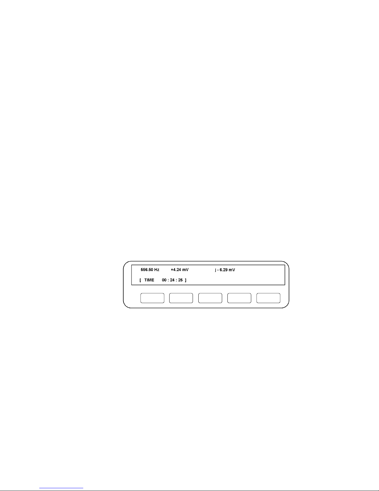
Frequency Response Analyzer Additional Generator Controls
AMK/1250/2 9-3
The other four keys control the rate at which the frequency is altered. They are graded
from "SLOW" through to "FAST" and respectively change the frequency in larger and
larger increments. These keys may be either pressed and released successively, in
which case the frequency will alter by one increment per press, or a key may be held in,
in which case the frequency will keep changing by the relevant increment until the
maximum or minimum value is reached, depending upon direction of change.
A warning "beep" indicates that the limit has been reached, and ERROR 43 will be
displayed briefly. As the FAST (coarse) key changes the frequency in relatively large
increments. a maximum or minimum limit will be reached which is inside the 1250's
capabilities. However, by then operating the slower (fine control) keys, the absolute
frequency limits can be obtained.
Note 1. The frequency shown here as "x.xxxx" is the last frequency entered. This will
be zero if the 1250 has just been initialised. To enter a new initial frequency upon which
the VARIABLE controls can operate, use the Generator Menu keys as described in
Chapter 4.
Note2. When "varying" frequency, the increments are linear below 1.0 Hz then
logarithmic from 1 Hz upwards.
Varying the Amplitude and Bias. These can be varied in a similar manner to that
described above for "Frequency".
Amplitude increments are linear from 0 to 1.0 V rms, then logarithmic thereafter.
Bias can go below 0 V, i.e. negative. The increments are linear between -1.0 V and
+1.0 V but logarithmic outside these values.
9.1.4 METHOD 2, WITH ANALYZERS RUNNING
When RECYCLE is pressed, the Display will resemble Fig. 9.2, assuming that the
chosen presentation of results is the a + j b form.
Figure 9.1 - Typical Display Analyzers Running.
The three entries in the top half of the Display show respectively Generator frequency,
the in-phase part of the reading (+4.24 mV) and the quadrature component (j - 6.29mV).
Page 73

Additional Generator Controls 1250 Frequency Response Analyzer
9-4 AMK/1250/2
When VARIABLE is pressed, the Display will change to just show: VARIABLE. [freq] as
before. When the required Generator parameter has been entered, the Display will
resemble Fig. 9.3.
Figure 9.3 - Typical Display with VARIABLE pressed and Analyzers running.
The soft keys can now be manipulated as in Method 1, but this time their effect can be
observed on the displayed reading. If the Generator frequency is being varied, the
current value is shown at the top left-hand end of the Display. If amplitude or bias are
being varied, the current value can be found by interrogating the STATUS facility.
9.1.5 USING VARIABLE WITH THE GENERATOR STOP @ KEY
The VARIABLE key can be used in conjunction with the GENERATOR STOP @ key.
For example, if it is required to set a hydraulic ram to a particular maximum extension,
but it is not known how this relates to the Generator peak amplitude, proceed as follows:
1. Set the Generator to the required frequency and waveform, but set the
amplitude to zero volts.
2. Press GENERATOR START. The Generator output will still be zero, so the ram
should not move.
3. Press STOP @ 90°. The Generator will stop at peak amplitude, albeit this is still
zero at the output terminals.
4. Press VARIABLE. By using the five soft keys as described previously, the peak
amplitude, and hence ram extension, can be varied until the required value is
found.
5. Press GENERATOR START. A continuous waveform, having the required
maximum value, will now appear at the output terminals.
Page 74
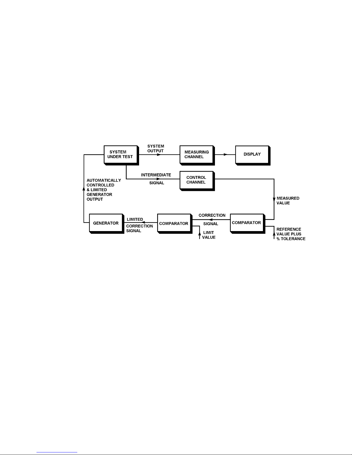
Frequency Response Analyzer Additional Generator Controls
AMK/1250/2 9-5
9.2 AMPLITUDE COMPRESSION
9.2.1 INTRODUCTION
It is sometimes desirable to control the amplitude of the signal at an intermediate point
in the measuring circuit, rather than at the Generator output. For example, the input to
an amplifier may need to be kept within close limits either side of the nominal value, to
avoid non-linear operation. With Amplitude Compression, the Generator output is
varied automatically to satisfy this condition, by using one of the Analyzer Channels as
part of a feedback control loop.
A safety feature is included in the control loop which limits the Generator output
amplitude to a 'safe' level selected by the user; this is explained in Section 2.3.
Fig. 9.4 shows the Amplitude Compression facility schematically.
Figure 9.4 - Amplitude Compression Schematic.
9.2.2 PRINCIPLE OF OPERATION
In the arrangement shown in Fig. 9.4, an intermediate signal is monitored at some point
within the system under test. The user defines the nominal voltage which is to be
maintained at this point and the percentage error that can be tolerated. For example, if
1 volt ± 25% is specified, the 1250 will attempt to hold the monitored voltage between
the levels 0.75 and 1.25 volts.
One of the Analyzer Channels is connected to the monitored point to form part of the
control circuit. The other Analyzer measures the output of the system under test. Both
Analyzers measure their respective signals simultaneously.
The Display is shown using the measuring Channel as its source, but it can use either or
both, as explained in Chapter 7.
If the Intermediate Signal is outside the tolerance band during a measurement, the 1250
does not display the invalid reading but attempts to correct the Generator output
appropriately before making a second measurement. The resulting reading is displayed,
valid or not, but "Error 84" is indicated with the reading if it is still invalid.
Page 75

Additional Generator Controls 1250 Frequency Response Analyzer
9-6 AMK/1250/2
Figure 9.5 - Amplitude Compression flow diagram.
Page 76

Frequency Response Analyzer Additional Generator Controls
AMK/1250/2 9-7
In order to hold the Intermediate Signal as closely as possible to its target value, and not
merely within the tolerance band, the 1250 computes and applies any correction
necessary to the Generator Output after displaying each reading.
The sequence of events is shown in the flow diagram, Fig. 9.5.
A typical sequence, when using Amplitude Compression with a Sweep, is shown
graphically in Fig. 9.6. The ERROR 84 condition does not occur in this example.
Figure 9.6 - Graphical Example of Amplitude Compression.
The solid curve represents the frequency response of the system under test, as it would
appear at the monitored point without Amplitude Compression. The sweep steps are
numbered from 1 to 10 along the base line.
Superimposed on this curve is the example quoted earlier of a nominal 1 volt level of
Amplitude Compression ± 25% error.
The dotted line shows the actual signal levels which appear at the monitored point as a
result of the Amplitude Compression. The numbers 1a, 1b, 2a, 2b etc. represent the
measurements made at each new frequency. Note that where the first measurement
shows the signal to be between the permitted levels, only one measurement is made,
e.g. at step 4.
9.2.3 GENERATOR OUTPUT LIMIT
If the Amplitude Compression feedback loop fails to gain control then the Generator
output steadily increases to the maximum value achievable, which could exceed some
prescribed 'safe' level for driving the system under test.
The LIMIT facility in the Amplitude Compression menu allows a maximum safe
operating amplitude to be specified which cannot be exceeded even if the compression
loop fails.
Page 77

Additional Generator Controls 1250 Frequency Response Analyzer
9-8 AMK/1250/2
9.2.4 SETTING THE MENU
To set up the Amplitude Compression facility, press GENERATOR MENU, then operate
the SELECT key until the Display shows [AMPL. COMPRESS] MENU. Five soft keys
will be assigned as follows:
SOURCE. The SELECT key allows either Channel 1 or Channel 2 to be allocated as
the control Channel, whichever is the most convenient to the user. The default state
selects Channel 1, which is useful if a point to point measurement is to be made.
Connect the input of the selected Channel to the point to be monitored.
VALUE. Enter the nominal value of the voltage that it is desired to maintain at the
monitored point.
ERROR%. Enter the percentage error that can be tolerated on the nominal voltage.
This figure often has to be a compromise. Whilst it is usually desirable to keep the error
as small as possible, it may be necessary to accept a wider tolerance, for reasons
discussed in Section 2.5.
LIMIT. Enter the safe operating Generator output voltage limit required.
COMPRESS. This key acts as the on/off control, the default state being "off”. Enter
"on" if the Amplitude Compression facility is required.
9.2.5 ERROR 84
Section 9.2.2 describes how ERROR 84 will be displayed if the corrected Generator
output still yields a wrong signal level at the monitored point. This can occur if the 1250
bases its correction ratio calculation on unsuitable data, and may necessitate increasing
the % ERROR value. There are three main reasons why the data may be unsuitable:
1. Excessive noise on the signal. The effect of this can be reduced by increasing
the ∫ TIME value.
2. The system under test parameters are not stable, e.g. the gain changes with
time.
3. The amplitude response of the system under test is non-linear.
When ERROR 84 appears in the Display during a Sweep with Amplitude Compression
on, a warning "beep" will sound. The Sweep is continued but ERROR 84 remains
displayed as a warning that there has been at least one non-valid reading. Any further
non-valid readings will also generate a "beep".
9.2.6 USE OF THE FILE
If a Sweep is left to run unattended, and the user wishes to know which, if any, readings
produced ERROR 84, all the readings should be stored in the File, as explained in
Chapter 12. These readings can then be replayed at a later date, as many times as
necessary, for analysis.
Page 78

10-1
10
Facilities For More Complex
Measurements
Section Page
10.1 The Function Key 10.2
10.1.1 Introduction 10.2
10.1.2 Angle Information 10.3
10.1.3 Multiplication Factors: Xωn 10.4
10.1.4 Scaling 10.5
10.1.5 Limits 10.6
10.1.6 Function Key Summary 10.7
10.2 Data Flow Schematic 10.8
Page 79

Facilities For More Complex Measurements 1250 Frequency Response Analyzer
10-2 CHFR/1250/1
10.1 THE FUNCTION KEY
10.1.1 INTRODUCTION
The FUNCTION key enables the result of a measurement to be processed in a variety
of ways, before it appears as a reading:
1. The user may choose from several angle conventions, based on degrees or radians.
2. As the measured values are sinusoidal, they can be integrated or differentiated by
multiplying by (jω)n, where n = ± 1 or ± 2.
3. The measured values can be scaled by suitable factors.
4. The measured values can be checked against high and low limits.
All the available functions are summarised in Section 1.6.
The File. If the measured results are stored in the File, as described in Chapter 12,
they can be processed prior to storing, then replayed from the File with a second set of
Limits applied, as indicated in the Data Flow schernatic of Section 2.
Page 80

1250 Frequency Response Analyzer Facilities For More Complex Measurements
CHFR/1250/1 10-3
10.1.2 ANGLE INFORMATION
Having pressed FUNCTION, followed by the ANGLE soft key, SELECT and ENTER
either "degree" or "radian". Each of these offers four choices of presentation, as
illustrated in Fig 10.1. ENTER the required choice.
Figure 10.1 - Angle Conventions
Page 81

Facilities For More Complex Measurements 1250 Frequency Response Analyzer
10-4 CHFR/1250/1
10.1.3 MULTIPLICATION FACTORS: x ωω
n
Pressing the x ωn soft key gives the user a choice of four multiplication factors, plus the
default state of "x unity" which is the "off" condition. The four choices are:
1. x (jω), which differentiates the value.
2. x (1/jω), which integrates the value.
3. x (jω)2, which double differentiates the value.
4. x (1/jω) 2, which double integrates the value.
Theory. A quantity which varies sinusoidally can be represented as a vector y rotating
at a constant angular velocity ω, as shown in Fig 10.2
Figure 10.2 - Representation of Vector Quantity
The peak value is indicated by the length r, and the phase angle with respect to the 0°
reference axis at any given moment, is θ. The vector can also be represented by a
complex number, in the form a + jb.
As can be seen firom Fig. 10.2:
y = a + jb = r (cos θ + j sin θ)
and, by Euler's Formula:
r (cos θ + j sin θ) = re
j
θ
For uniformly rotating vectors, the phase angle θ is a linearly varying function of time
i.e.: θ = ωt
thus y = re
jωt
and dy/dt = jωre
jwt
Hence the original quantity has been differentiated by multiplying by jω.
The other three multiplying factors act in a similar fashion. Note that this method only
applies to sinusoidal functions.
Applications. Where a required parameter cannot be measured directly, it is often
possible, by using a suitable transducer, to measure a related function. One of the
multiplying factors can then be applied to the results to derive the required data. For
example, Fig. 10.3 illustrates how various mechanical parameters can be derived from
one another by using the X ωn factors.
Page 82

1250 Frequency Response Analyzer Facilities For More Complex Measurements
CHFR/1250/1 10-5
Figure 10.3 - Use ofMultiplication Factors
10.1.4 SCALING
Pressing the SCALE soft key gives the user a choice of three scaling factors whereby
the result of a measurement can be divided by a vector. There is also a default state of
"divide by unity", which is the "off” condition.
The next two choices are:
1. DIVIDE BY [a, b]
2. DIVIDE BY [r, θ ]
3. If either of these is entered, the Display will request further information. For
example, if [a, b] is entered, following an initialisation, the Display will show:
a not entered (+ )V
Enter the required value for "a" in the round brackets; all numerical scaling values can
be up to five digits plus decimal point and exponent. The Display will now show:
b not entered (+ )V
Enter the required value for "b". The Display will revert to show FUNCTION plus the
soft keys.
If [a, b] is now entered again, the current value will have replaced the "not entered"
message e.g.:
a "current value" (+ )V
Similarly, if scaling values had already been entered for a previous measurement, with
no subsequent initialisation, these would have appeared instead of "not entered".
The setting up of [r, θ ] is similar, except that θ is given in degrees.
The third choice is:
DIVIDE BY [last result]. This mode can be used where relative, rather than absolute,
measurements are to be made. A series of results is divided by a selected reference
value which is measured at some point in the sequence, usually at the beginning.
The reference measurement is first completed, and then DIVIDED BY [last result] is
entered. This causes the result of the measurement to be stored, and all subsequent
results will be divided by this value.
Page 83

Facilities For More Complex Measurements 1250 Frequency Response Analyzer
10-6 CHFR/1250/1
10.1.5 LIMITS
The LIMIT soft key enables the user to assign a pair of values, called Upper and Lower
Limits, to any one of five parameters. The measured results can then be compared to
these values, results between the Limits being defined as Passes, those outside as
Fails.
Press the FUNTION key, followed by the LIMIT soft key. The default state is "off”,
followed by the five parameter choices obtained by operating the SELECT key, as
follows:
LIMIT CHECK [on a], [on b], [on r], [on θ] and [on log r].
Enter the required parameter. For any choice other than "off", the Display will request
further information.
For example, if [on a] is entered, following an initialisation, the Display will show:
UPPER LIMIT not entered (+ )V
Enter the required value for the Upper Limit in the round brackets; all Limit values can
be up to five digits plus decimal point and exponent. The Display will now show:
LOWER LIMIT not entered (+ )V
Enter the required Lower Limit. The Display will revert to show FUNCTION plus the soft
keys.
If [on a] is now accessed again, the current value will have replaced the "not entered"
message e.g.:
UPPER LIMIT "current value" (+ )V
Similarly, if Limits had already been entered for a previous measurement, with no
subsequent initialisation, these would have appeared instead of "not entered".
The setting up of Limits on the other parameters is similar, except that θ is in degrees
and log r in dB.
Limits can be set on only a single parameter at a time, namely the parameter last
SELECTed. which appears in square brackets:
LIMIT CHECK [on "parameter"].
If the measurement results have been stored in the File, new limits may be applied to
the original or to another parameter, when the results are read back from the File.
Page 84

1250 Frequency Response Analyzer Facilities For More Complex Measurements
CHFR/1250/1 10-7
10.1.6 FUNCTION KEY SUMMARY
Soft Key Display Displayed Choices
ANGLE ANGLE [degree] CONVENTION [-180 to +180ant. clk] (Default State}
↑
CONVENTION [0 to 360 ant. clk} SELECT and
(SELECT and CONVENTION [-360 to 0 ant. clk} ENTER
ENTER either) CONVENTION [0 to 360 clkwise]
↓
ANGLE [radian] CONVENTION
[-π to +π ant. clk]
SELECT and
CONVENTION
[0 to 2π ant.clk]
ENTER
CONVENTION
[-2π to 0 ant.clk]
CONVENTION
[0 to 2π clkwise]
xω
n
MULTIPLY BY [unity] (Default State}
[jω]
SELECT and ENTER
[1/jω]
[jω2]
[1/jω2]
SCALE DIVIDE BY [unity] (Default State}
[a, b] SELECT and ENTER
[r, θ]
See Note 1.
[last result]
Note 1. If {a, b] or [r, θ] is selected, values for a and b,
or r and θ respectively must also be entered.
LIMIT LIMIT CHECK [off] (Default State}
[on a] SELECT and ENTER
[on b] See Note 2.
[on r]
[on θ]
[on log r]
Note 2. For any choice other than “off”, Upper and
Lower Limit values must be entered.
Page 85

Facilities For More Complex Measurements 1250 Frequency Response Analyzer
10-8 CHFR/1250/1
10.2 DATA FLOW SCHEMATIC
Each stage is represented by a box. Where the box has two sections, the upper
contains the title of the facility and the lower shows the relevant Front Panel key.
Boxes shown shaded, such as LIMIT CHECK, are optional facilities which may be
placed in the data path by the relevant key. If not switched in, they have no effect on
the data.
The main data path is shown in heavy line.
ANALYZER 1 ANALYZER 2
OTHER
ANALYZERS
DISPLAY SOURCE
DISPLAY / PLOTTER MENU
xωn and SCALE
FUNCTION
LIMIT CHECK 1
FUNCTION
FILE
OFF/ALL/FAIL/PASS
DATA OUTPUT
FILE OUTPUT
VIEW FILE
LIMIT CHECK 2
FUNCTION
PLOTTER X ITEM & Y ITEM
DISPLAY / PLOTTER MENU
ANGLE CONVENTION
FUNCTION
ANGLE CONVENTION
FUNCTION
CO-ORDINATE SELECTION
DISPLAY / PLOTTER MENU
RS423
OFF/ALL/FAIL/PASS/DUMP
DATA OUTPUT
GPIB
OFF/ALL/FAIL/PASS/DUMP
DATA OUTPUT
PLOTTER
INTERFACE/GPIB
DISPLAY/PLOTTER
DISPLAY
OFF/ALL/PASS/DUMP
DATA OUTPUT
LIMIT CHECK 1
FUNCTION
Page 86

11-1
11
Additional Displayed Information
Section Page
11.1 The Status Key 11.2
11.1.1 Introduction 11.2
11.1.2 Using the Key 11.2
11.1.3 Main Status 11.3
11.1.4 Other Status 11.5
11.1.5 Printed Record 11.8
11.2 Error Codes 11.9
11.2.1 Introduction 11.9
11.2.2 Error Codes: Summary 11.9
11.3 Error Codes: Details 11.11
11.3.1 Introduction 11.11
11.3.2 Group 0. Errors Pertaining to Command Structure 11.11
11.3.3 Group 1. Errors Pertaining to the Learnt Program 11.12
11.3.4 Group 2. Parametric Interaction Errors. 11.12
11.3.5 Group 3. Generator Warnings and Errors 11.12
11.3.6 Group 4. Learnt Program, File and Variable 11.13
11.3.7 Group 5. Missing Boards 11.13
11.3.8 Group 6. Illegal I/O Manipulation 11.14
11.3.9 Group 7. System Errors 11.14
11.3.10 Group 8. Measurement Validity is Suspect 11.14
Page 87

Additional Displayed Information 1250 Frequency Response Analyzer
11-2 AMK/1250/3
11.1 THE STATUS KEY
11.1.1 INTRODUCTION
The STATUS key, in conjunction with the SELECT key, enables the user to examine,
but not alter, the current state of the controls and the existing parameter values in the
1250. Quantities displayed in lower case are usually those which the user has entered,
whereas those in upper case indicate the state of the instrument. In the details that
follow, where one of several different states may appear after a particular heading, all
the possible states are listed in the form: RUN/STOP/IDLE/etc.
The Status information is available under two headings, [MAIN] STATUS which includes
the Menus, and [OTHER] STATUS which covers the rest of the instrument. Nine soft
key titles are allocated, details of which are given in Sections 11.1.3 and 11.1.4. The
soft key titled "µP" gives information on the 1250 Central Processing Unit, as described
in Section 1.4.
11.1.2 USING THE KEY
To view the STATUS information, press the STATUS key. The Display will show:
[MAIN] STATUS with soft keys: GEN (i.e. Generator)
ANALYZER
SWEEP
DISPLAY
PLOTTER
If SELECT is pressed, the Display will change to:
[OTHER] STATUS SYNC (i.e. Synchroniser)
FN/PROG (i.e. Function/Program)
µP (i.e. the 1250 Central Processor Unit)
GPIB
Having selected the required STATUS group, press the relevant soft key. The format of
the information which now appears in the Display is referred to as a "page". Several
pages are available for each soft key. To step through the pages, successively operate
the SELECT key, (although in this case no square-bracket prompt is given).
Having obtained the required page, and verified the status of the parameter concerned,
press ENTER to retrieve the soft key display. Alternatively, to exit from the STATUS
mode completely, press the key for the next operation that is to be performed.
Page 88

1250 Frequency Response Analyzer Additional Displayed Information
AMK/1250/3 11-3
11.1.3 MAIN STATUS
Soft Key Page Display
GEN 1 GENERATOR RUN/STOP/FAULT WAVEFORM sine/square/triangle
CARRIER NONE/LO/on MODoff/1on/2on
Notes: GENERATOR FAULT indicates that the Generator board is
missing.
CARRIER NONE indicates that no Modulator/Demodulator
board is fitted.
CARRIER LO indicates that a carrier is present, but at
insufficient amplitude.
2 FREQ (Hz) AMP (V) BIAS (V)
value value value
Note: The units of frequency and voltage remain constant; exponent
notation is used to cover the full range.
3 AMP. COMPRESS VALUE (V) ERROR (%)
off/on Ch01/on Ch02 value value
4 AUX. GEN NONE
unless the optional Auxiliary Generator is fitted, in which case the
Display reads:
AUX. GEN RUN/STOP WAVEFORM sine/square/triangle
Note: CARRIER and MOD are not displayed; these will be as for Main
Generator. A further page is available for the Auxiliary
Generator.
5 AUX. GEN AMP (V) BIAS (V)
value value
ANALYZER 1 ANALYZERS STOP/RUN/IDLE/DELAY/WAIT* RUN TIME (sec)
AUTO-INT off/short on Ch01/short on Ch02 / value =
/long on Ch01/Iong on Ch02
*WAIT signifies that the Analyzer is ready, but waiting for another
section of the 1250.
=This value shows the time taken for the last measurement completed.
2 INT.TIME (sec/cyc) M. DELAY (sec/cyc) HARMONIC
value value 01
Note: HARMONIC will show a number from 1 to 16.
3 Ch RANGE DEMOD INPUT COUPLING
01 auto/30mV/ off/1 on/2 on front/rear DC/AC
300mV/3V/
30V/300V
4 Ch 02 as for Ch 01
Note: The Display will show only the Channel numbers of Analyzers
which are fitted. If additional Analyzers are present, the status of these
will be shown on subsequent pages, in the sequence: Ch11 to Ch18,
Ch21 to Ch28, Ch31 to Ch38, and Ch41 to Ch48.
Page 89

Additional Displayed Information 1250 Frequency Response Analyzer
11-4 AMK/1250/3
MAIN STATUS (cont.)
Soft Key Page Display
SWEEP 1 SWEEP STOP/IDLE/HOLD/RUN TYPE harm up/lin/up/
lin down/log up/log down
2 F. MIN (Hz) F. MAX (Hz) *
value value value
* For LOG: st/dec or st/oct or st/swp or ratio
For LIN: st/swp or step (Hz)
where st = step, dec = decade, oct = octave, swp = sweep.
For HARMONIC there is no entry.
DISPLAY 1 DISPLAY Ch01 to 48 or Ch n/m IN a,b / r,theta / log r,theta
RANGE value *
* e.g. 3V. This figure shows the range used in the last completed
measurement, even where the Analyzer is on Auto-Range. If a ratio
measurement was made, both ranges will be shown e.g. 3V/30mV.
PLOTTER 1 PLOTTER STOP/IDLE/RUN/NONE X-Ch *
A3/A4 point/vector Y-Ch
* The Channel number will be given as for DISPLAY, followed by
a/b/r/theta deg/theta rad/log r dB/ƒ Hz/logƒ Hz.
2 X-MIN X-MAX X-ORIGIN
value value value
3 Y-MIN Y-MAX Y-ORIGIN
value value value
Page 90

1250 Frequency Response Analyzer Additional Displayed Information
AMK/1250/3 11-5
11.1.4 OTHER STATUS
Soft Key Page Display
SYNC 1 SYNC. NONE/IDLE/WAIT/STABLE/LOCKED/FAULT
followed by a single digit fault identifier.
Further pages appear only if synchroniser option is fitted.
2 TRIG LEVEL RATIO SLOPE COUPLING
value value +/- AC/DC
3. INPUT FREQ MIN FREQ MAX FREQ
value value value
4. START FREQ STOP FREQ AVGE FREQ
value value value
FN/PROG 1 PROGRAM 1 2 3 4 5 6 7 8 9
LEARNT *L
*L appears under every learnt program.
2. NV PROGRAM 10 11 12 13 14 15 16 17 18
LEARNT *L
*L appears under every learnt program. To learn programs 10 to 18 the
keyswitch must be in the ‘Supervisor’ position.
3. FUNCTION ANGLES deg/rad - to + ant. clk. or
0 to + ant. clk or
- to 0 ant. clk or
0 to + clkwise
Note: “- to +” signifies -180° to +180° for degrees or -π to +π for radians
“0 to +” signifies 0 to 360° for degrees or 0 to 2π for radians
“- to 0” signifies -360° to 0 for degrees or -2π to 0 for radians
4. FUNCTION LIMIT CHECK off/ on a/ on b/ on r/ on theta/ on log r
SCALED BY unity/ a,b/ r,theta/ last result *
Note: If xωn has been selected, the area of the display marked * above
will show one of the following:
and jω, and 1/(jω), and (jω) ↑ 2, and 1/(jω) ↑ 2.
Where “ ↑ 2 “ indicates “squared”.
5 SCALING a b
FACTORS value value
6 SCALING r theta
FACTORS value value
7 LIMIT a LO a HI
VALUES value value
8 LIMIT b LO b HI
VALUES value value
Page 91

Additional Displayed Information 1250 Frequency Response Analyzer
11-6 AMK/1250/3
9 LIMIT r LO r HI
VALUES value value
10 LIMIT theta LO thata HI
VALUES value value
11 LIMIT log r LO log r HI
VALUES value value
µµP 1 PROCESSOR MODE LAST ERROR
READY/BUSY/ SUPERVISOR/ See Note 1
PROGRAM*/pause NORMAL
* PROGRAM indicates that the microprocessor is occupied in working
through a program: BUSY indicates that it is engaged on some other
activity. Pause indicates that it is waiting for a user input.
The three position keyswitch on the rear panel of the 1250 allows the
user to set the operating mode to 'Supervisor', 'Operator' or 'Normal'.
Supervisor/Normal enable/disable writing to the permanent memory
respectively. The 'Operator' position is reserved for future use, but at
present has the identical effect as 'Normal'.
Note 1: The Error Codes for the last three errors noted are displayed
here. For example, the display could show: 01 21 59. The latest
appears on the left, in this case 01.
As new errors are detected, the existing numbers shift to the right, such
that if the next error code is code. 70, the display changes to:
70 01 21.
2 FREE MEM PROGRAM NV PROGRAM FILE
BLOCKS value value value
Memory in the 1250 is of two types:
a. Memory assigned to the File (see Chapter 12 Section 2). The File is
used for storing results and has a capacity of 470 blocks, each block
capable of holding one File result.
b. Memory assigned to storing learnt programs. This section divides into
two memory locations:
i. A permanent 'Supervisor' memory. This has a capacity of 508
blocks, each block capable of holding one line of program. Nine
separate programs may be stored in this memory (Nos. 10 to 18)
providing that the keyswitch on the rear panel is in the 'Supervisor'
position. This memory location is refered to as NV PROGRAM in
this status page.
ii. A battery backed 'Normal' memory, which will retain information
for at least 100 hours while the instrument is switched off. This
has a capacity of 500 lines of program and allows the storage of
nine separate programs (Nos. 1 to 9). This is refered to as
PROGRAM in this status page.
Page 92

1250 Frequency Response Analyzer Additional Displayed Information
AMK/1250/3 11-7
µµP (cont.)
Page Display
3 LAST UPPER LOWER
LIMIT value value
This page can be used to determine the limits which apply to the current
parameter being entered, as an alternative to looking it up in the full
specification. For example, if the maximum Generator output voltage is
not known, enter an arbitrary value in the Generator menu. This can be
either a known permissible value, e.g. 1 Volt, or an excessive value
such as 90 Volts. Now call up page 3 of the microprocessor status, and
the available limits for the Generator output voltage will he displayed.
4 DATA GPIB RS423 DISPLAY FILE
O/P off/ off/ off/ off/
all/ all/ all/ all/
fail/ fail/ fail/ fail/
pass/ pass/ pass/ pass/
dump dump
Note: see Chapter 12, DATA OUTPUT key, Section 1.2 for explanation
of above messages.
5 REFORMAT HEADING
on/off on/off
Note: see Chapter 12, DATA OUTPUT key, Section 1.3 for explanation
of above messages.
GPIB 1 GPIB MODE STATE ADDRESS
t.only/ IDLE/ e.g. 00/10
normal maj TACS/
min TACS/
maj LACS/
min LACS
Notes: where t. = talk, normal = bi directional, maj = major, min = minor
TACS =Talker Active State LACS = Listener Active State
The pair of numbers appearing under "ADDRESS" are the major and
minor addresses respectively, as explained in Chapter 13, section 5.1.
Page 93

Additional Displayed Information 1250 Frequency Response Analyzer
11-8 AMK/1250/3
GPIB (cont.)
Soft Keys Page Display
2 GPIB SER. POLL PAR. POLL CONTROL
8 digits, consisting A number local/
of a set of “flags” from 0 to 8 remote/
and a “service” 0 = disabled loc + llo/
bit. rem + llo
followed by sense:
T = True
F = False
Note: SER = Serial PAR = Parallel llo = Local lock-out
For further explanation of these messages, see the GPIB section,
Chapter 13, Section 7.
3 GPIB I/P TERM O/P TERM O/P SEP
lf/cr/s-colon/EOI crlf/crlf+EOI/ comma/term
cr/cr+EOI
Notes: TERM = Terminator, SEP = Separator
cr = carriage return, lf = line feed, EOI = End or Identify.
Where "term" appears under 0/P SEP, it means that the Output
Separator is the same as the Output Terminator. Further information
appears in the GPIB section, Chapter 13.
11.1.5 PRINTED RECORD
If a printed record is required of the STATUS information, enable the relevant output
device as described under DATA OUTPUT. Any state other than off will cause the data
to be printed; the pass/fail conditions do not apply here. Note that STATUS information
is not available via the GPIB.
Press STATUS, then the relevant soft key. It is only necessary to use SELECT to
change from [MAIN] to [OTHER] STATUS; the pages will be "scrolled" automatically to
the output device when the soft key is pressed. Note, however, that only the first page
for each soft key will appear in the Display.
Page 94

1250 Frequency Response Analyzer Additional Displayed Information
AMK/1250/3 11-9
11.2 ERROR CODES
11.2.1 INTRODUCTION
The Error Codes fall into two main categories:
a. Those which explain why the instrument has stopped; some of these are warnings
rather than errors.
b. Those which explain why the instrument will not respond to a new command.
Some of the code numbers appear only briefly in the Display, accompanied by a
warning "beep". However, they can always be recalled as described under STATUS, µP,
1st page.
If a Code Number appears in the Display, but is not in the following list, it is intended for
Service Engineer's use only.
11.2.2 ERROR CODES: SUMMARY
The Error Codes are assigned in groups as follows:
Group 0 = Errors Pertaining to Command Structure
01 Unknown command
02 Argument mismatch
03 Argument out of range
04 Floating point format error
05 Illegal request for value
Group 1 = Programming Errors
11 Illegal edit command
12 Command cannot be learnt
13 Program does not exist
14 Recursion attempted
15 Attempt to edit while program is running
16 Program Check Sum error
17 Program Exists
18 Copy complete
Group 2 = Parametric Interaction Errors
21 The combination of Frequency and Harmonic is > 65kHz
22 The combination of some or all of Generator Amplitude, Bias, Waveform and
Modulation gives > 15V peak (21V for 1250N)
23 The combination of some or all of auxiliary Generator Amplitude, Bias,
Waveform and Modulation gives > 15V peak (21V for 1250N)
24 The combination of Frequency, Harmonic and Integration Time is out of range
25 Plotter MINIMUM> MAXIMUM
26 Order Analysis incompatibility
Group 3 = Generator Warnings and Errors
30 Generator stopped by command
31 Generator overload or Generator power failure
32 (Spare code)
33 Auxiliary Generator overload or Auxiliary Generator power fail
34 Modulation Channel 1 overload
35 Modulation Channel 2 overload
Page 95

Additional Displayed Information 1250 Frequency Response Analyzer
11-10 AMK/1250/3
ERROR CODES: SUMMARY (cont.)
Group 4 = Learnt Program, File and Variable
41 Line number not found
42 Jump outside Program mode
43 Attempt to step variable out of range
44 File empty
45 Illegal File access
46 Illegal File size entry
Group 5 = Missing Boards
50 Analyser not present
51 (Spare code)
52 (Spare code)
53 Generator not present
54 Control not present
55 Synthesizer not present
56 Mod/Demod not present
57 Synchroniser not present
58 Auxiliary Generator not present
59 Plotter not present
Group 6 = Illegal I/O Manipulation
60 Changing I/O device during Learn sequence
61 Attempt to change operating conditions from a non enabled I/O device
Group 7 = System Errors
70 Out of Memory
71 NVRAM Corrupted
72 Not Supervisor
Group 8 = Measurement Validity is Suspect
81 Overload
82 Auto Integration terminated before valid completion
83 A combination of 81 and 82
84 Amplitude Compression failure
85 A combination of 81 and 84
86 A combination of 82 and 84
87 A combination of 81, 82 and 84
88 Internal Hardware Error
89 Analysis terminated early, by ANALYZER STOP key
Group 9 = Synchroniser and Slave Analyzer Errors
91 (Spare Code)
92 (Spare Code)
93 (Spare Code)
94 Synchroniser not Ready
95 No results available from Slave Analyser(s)
96 (Spare Code)
97 (Spare Code)
98 (Spare Code)
Page 96

1250 Frequency Response Analyzer Additional Displayed Information
AMK/1250/3 11-11
11.3 ERROR CODES: DETAILS
11.3.1 INTRODUCTION
Where the Error Code appears only in the Summary, the Code title is deemed to be
self-explanatory.
Some of the Codes which refer to faulty modules are primarily intended to give
information to Service Engineers.
11.3.2 Group 0. ERRORS PERTAINING TO COMMAND STRUCTURE
01 Unknown command: is caused when a peripheral device sends a command which
the 1250 does not recognise.
02 Argument mismatch. The instructions to the 1250 usually consist of two parts: the
"command" e.g. FR for frequency, and the numerical part or "argument" e.g. 45 plus
exponent. Hence a typical simple instruction would be FR 2E3, meaning "set the
Frequency to 2 kHz".
Where there is more than one device, e.g. two Analyzers, the Argument must specify
not only the numerical value, but also the device. For example: RA 1, 3 means set the
Analyzer voltage range (RA), of Analyser 1, to Range 3. When the 1250 sees RA, it
expects to see two other pieces of numeric information following. If it only sees one,
this is detected and flagged as an Argument mismatch.
Conversely, if the instruction should contain only one piece of numeric information, but
owing to an error contains two, this is also flagged as an Argument mismatch.
03 Argument out of range, i.e. outside the range of the 1250. This error can be
caused by incorrect use of front panel keys, as well as by invalid instructions from a
peripheral device. An example is trying to programme a frequency of 1 MHz, which is
above the maximum frequency of 65 kHz.
04 Floating Point format error. Usually caused by a typing error, e.g.FR 1•25E2 typed
as FR 1•2•5 E2.
05 Illegal request for value, of a parameter or mode which does not possess a value.
For example, if the peripheral device sends ?SG to the 1250, meaning "what value is
Stop Generator", 05 will be flagged.
Page 97

Additional Displayed Information 1250 Frequency Response Analyzer
11-12 AMK/1250/3
ERROR CODES: DETAILS (cont.)
11.3.3 GROUP 1. ERRORS PERTAINING TO THE LEARNT PROGRAM
11 Illegal edit command. The four Edit commands are listed in the Program Learn
section. Once the Edit mode has been established, the only valid commands from a
peripheral are these four plus the Edit Complete signal *Q. Any other command will
produce ERROR 11.
If editing from the front panel, the correct way to exit from the Edit mode is to press the
QUIT softkey.
12 Command cannot be Learnt. In the Program Learn mode there are certain
commands which cannot be learnt, such as Edit Command, when given from a
peripheral device.
13 Program does not Exist. The STATUS display, soft key FN/PROG, page 1 shows
the nine available Learnt Program numbers, with an L beneath those which have been
learnt. Any attempt to e.g. Execute or Clear a Program whose number has no L
allocated will produce error 13.
14 Recursion attempted. Recursion in this case is defined as: "a program A, which,
whilst being executed, either calls itself or calls a program B, which in turn calls program
A". This is only allowed under special circumstances, as described in Chapter 12.
16 Program Check Sum error. Learnt programs are stored in the 1250 memory; a
check sum is calculated and stored with the program data. Before a stored program can
be operated upon, a new check sum is calculated, and compared with the original. If the
two disagree, the stored data is presumed to have been corrupted. The operation will
not be performed and ERROR 16 will be displayed.
17 Program Exists. An attempt has been made to copy into a program which already
exists. This program must he cleared before any new program may be copied to it.
18 Copy complete. Specified program has been copied.
Learnt Program operations are described in Chapter 12.
11.3.4 GROUP 2. PARAMETRIC INTERACTION ERRORS
26 Order Analysis incompatibility. Order Analysis selected with Auto Integration or
with Frequency > 650Hz (400Hz when Synchronising); or Order Analysis attempted on
an incomplete measurement (e.g. if BREAK pressed during a measurement).
11.3.5 GROUP 3. GENERATOR WARNINGS AND ERRORS
30 is a warning that the generator has stopped. For example, operating the
GENERATOR STOP key will call up ERROR 30.
31 and 33 mean that an excessive external voltage has been applied across the
Generator terminals.
34 and 35 indicate that an excessive modulating signal is being applied.
Page 98

1250 Frequency Response Analyzer Additional Displayed Information
AMK/1250/3 11-13
These five Error Code numbers only appear when page 1 of the µP Status is displayed.
The "Errors and Warnings" field of the Display will show one of the following messages,
but no number.
Message Error Code Number
GEN. STOPPED 30
GEN. O/LOAD 31
AUX. GEN O/L 33
MOD. Ch 1. O/L 34
MOD. Ch 2. O/L 35
11.3.6 GROUP 4. LEARNT PROGRAM, FILE, AND VARIABLE
41 Line number not found, in Learnt Program. This only applies when the Learnt
Program has been compiled using a peripheral device, in which case each line of the
program may be allocated a number. Jump instructions can then be used for program
looping etc., using the line numbers as addresses.
If a command is given to jump to a line number which does not exist in the current
program, ERROR 41 will be displayed.
42 jump outside Program mode: refers to Learnt Program, but only when using a
peripheral device. The 1250 will obey a Jump instruction when it forms part of a
program which is being run from the Memory, but not when it is sent directly from an
external keyboard.
For example, the stored program may contain:
Line 06 JP20 CR, meaning jump from Line 6 to Line 20. This jump will be executed
when running the program from Memory. However, if the program is loaded into
Memory, and the command JP20 is sent from the keyboard to try and start the program
from Line 20, ERROR 42 will be displayed.
43 Attempt to step Variable out of range. Also applies to an attempt to use Variable
on a parameter whose value has not been entered.
44 File empty, will be displayed in response to the [LIST]FILE command or the
[DISPLAY]FILE command if the File is empty. However [CLEAR]FILE may still be
used.
45 Illegal File Access. It is illegal to try to Display, List or Clear the File whilst the
Analyzers are running, or if they have been stopped in mid-measurement (by means of
the Generator Stop key).
46 Illegal File size entry. Attempt to change File size during a measurement; or to
reduce File size without first clearing; or to enter a File size greater than the number of
free Blocks available.
11.3.7 GROUP 5. MISSING BOARDS
An Error Code number in this Group will be displayed only if the 1250 is commanded to
perform an operation requiring a board or boards which are not fitted, e.g. if Modulation
is programmed but no Mod/Demod board is present.
Page 99

Additional Displayed Information 1250 Frequency Response Analyzer
11-14 AMK/1250/3
ERROR CODES: DETAILS (cont.)
11.3.8 GROUP 6. ILLEGAL I/O MANIPULATION
60 Changing I/O Device during Learn sequence. This error indicates that the 1250
was in the Learn mode prior to the command which attempted to change the I/O device.
As a result of this command, not only has the I/O device been changed; but the Learnt
Program has also been terminated automatically. However, the program prior to the
change of I/O device will have been learnt correctly and is therefore usable up to that
point.
61 Attempt to change operating conditions from a non-enabled I/O device. There
are three Input/Output routes to the 1250s Central Processor Unit (CPU):
a. Via the front panel
b. Via the RS423 port
c. Via the GPIB
ERROR 61 will be displayed when:
1. The GPIB is controlling the CPU with Local Lock-Out asserted, and an attempt is
made to send commands via the front panel or the RS423 port. The GPIB must
remove the Local Lock-Out first.
2. The GPIB is controlling the CPU with no Local Lock-Out, and an attempt is made to
send commands via the front panel or the RS423 port without first asserting "Local."
3. The CPU is being controlled via the RS423 port or the front panel, and an attempt is
made to send commands via the GPIB without first asserting "Remote."
4. The CPU is being controlled via the RS423 port and an attempt is made to send
commands via the front panel, without first pressing LOCAL.
11.3.9 GROUP 7. SYSTEM ERRORS
70 Out of Memory. There is a finite amount of unassigned memory available for
learning programs and storing readings on the File. Once all this memory has been
filled, any further demand will produce ERROR 70.
71 NVRAM corrupted. The non volatile memory has not been initialised or its contents
are invalid. To recover from this situation, set the keyswitch to "Supervisor" mode and
initialise the 1250.
72 Not Supervisor. An attempt has been made to alter the contents of the non volatile
(EEPROM) memory when in "normal" mode. To alter the contents of the non volatile
memory, the keyswitch must be in the "Supervisor" position.
Page 100

1250 Frequency Response Analyzer Additional Displayed Information
AMK/1250/3 11-15
11.3.10 GROUP 8. MEASUREMENT VALIDITY IS SUSPECT
Mainly covers conditions under which a valid measurement may not have been
achieved. The 1250 will display a reading accompanied by the appropriate warning code
number.
 Loading...