

Page 1

Installation Guide
Three Phase System with
SetApp Configuration
For Europe and APAC
Version 1.2
Page 2

Disclaimers 1
Disclaimers
Important Notice
Copyright © SolarEdge Inc. All rights reserved.
No part of this document may be reproduced, stored in a retrieval system or
transmitted, in any form or by any means, electronic, mechanical, photographic,
magnetic or otherwise, without the prior written permission of SolarEdge Inc.
The material furnished in this document is believed to be accurate and reliable.
However, SolarEdge assumes no responsibility for the use of this material. SolarEdge
reserves the right to make changes to the material at any time and without notice. You
may refer to the SolarEdge web site (www.solaredge.com) for the most updated version.
All company and brand products and service names are trademarks or registered
trademarks of their respective holders.
Patent marking notice: see http://www.solaredge.com/patent
The general terms and conditions of delivery of SolarEdge shall apply.
The content of these documents is continually reviewed and amended, where
necessary. However, discrepancies cannot be excluded. No guarantee is made for the
completeness of these documents.
The images contained in this document are for illustrative purposes only and may vary
depending on product models.
Three Phase System Installation Guide MAN-01-00505-1.2
Page 3
2 Emission Compliance
Emission Compliance
This equipment has been tested and found to comply with the limits applied by the
local regulations. These limits are designed to provide reasonable protection against
harmful interference in a residential installation. This equipment generates, uses and
can radiate radio frequency energy and, if not installed and used in accordance with
the instructions, may cause harmful interference to radio communications. However,
there is no guarantee that interference will not occur in a particular installation. If this
equipment does cause harmful interference to radio or television reception, which can
be determined by turning the equipment off and on, you are encouraged to try to
correct the interference by one or more of the following measures:
Reorient or relocate the receiving antenna.
Increase the separation between the equipment and the receiver.
Connect the equipment into an outlet on a circuit different from that to which
the receiver is connected.
Consult the dealer or an experienced radio/TV technician for help.
Changes or modifications not expressly approved by the party responsible for
compliance may void the user’s authority to operate the equipment.
-Three Phase System Installation Guide MAN-01-00505-1.2
Page 4
Support and Contact Information 3
Support and Contact Information
If you have technical problems concerning SolarEdge products, please contact us:
Country Phone E-Mail
Australia (+61) 1800 465 567
APAC (Asia Pacific)(+972) 073 240 3118
Belgium (+32)
0800-76633
China (+86) 21 6212 5536
DACH & Rest of Europe (+49) 089 454 59730
France (+33) 0800 917410
Italy (+39) 0422 053700
Japan (+81) 03 6262 1223
Netherlands (+31) 0800-7105
New Zealand (+64) 0800 144 875
Republic of Ireland (+353) 1800-901-575
United Kingdom (+44) 0800 028 1183
US & Canada (+1) 510 498 3200
Greece (+49) 89 454 59730
Israel (+972) 073 240 3122
Middle East &Africa (+972) 073 240 3118
South Africa (+27) 0800 982 659
Turkey (+90) 216 706 1929
Worldwide (+972) 073 240 3118
support_
[email protected]
Before contact, make sure to have the following information at hand:
Model and serial number of the product in question.
The error indicated on the Inverter SetApp mobile application or on the
monitoring platform or by the LEDs, if there is such an indication.
System configuration information, including the type and number of modules
connected and the number and length of strings.
The communication method to the SolarEdge server, if the site is connected.
The inverter software version as appears in the status screen.
Three Phase System Installation Guide MAN-01-00505-1.2
Page 5
4 Revision History
Revision History
Version 1.2 (Feb 2019)
Added appendix 'Determining the Circuit Breaker Size' and paragraph
referencing to it, in the 'Grid Connection Guidelines' section.
Updated guidelines for use of extension cables in power optimizer installation
Torque for plastic cover screws 10.3 N*m/ 7.5 lb-ft.
In Specifications:
Addition of footnote for MC4 inputs: Connection of additional strings in
parallel to a single input is allowed as long as the cumulative current
does not exceed 45A.
Removed the 'Recommended circuit breaker/ fuse size to use at the grid
connection point' table.
Version 1.0 (Aug. 2018)
Initial release
-Three Phase System Installation Guide MAN-01-00505-1.2
Page 6
Revision History 5
Contents
Disclaimers 1
Important Notice 1
Emission Compliance 2
Support and Contact Information 3
Revision History 4
HANDLING AND SAFETY INSTRUCTIONS 7
Safety Symbols Information 7
IMPORTANTSAFETYINSTRUCTIONS 8
Chapter 1: Introducing the SolarEdge Power Harvesting Syste m 10
Power Optimiser 10
Inverter 11
Monitoring Platform 11
Installation Procedure 11
Installation Equipment List 11
Inverter Transport and Storage 12
Chapter 2: Installing the Power Optimizers 13
Safety 13
Installation Guidelines 14
Step 1: Mounting the Power Optimizers 17
Step 2: Connecting a PV Module to a Power Optimiser 17
Step 3: Connecting Power Optimizers in Strings 18
Step 4: Verifying Proper Power Optimiser Connection 19
Chapter 3: Installing the Inverter 20
Inverter Package Contents 20
Identifying the Inverter 20
Inverter Interfaces 20
Mounting the Inverter 25
Chapter 4: Connecting the AC and the Strings to the Inverter 30
Grid Connection Guidelines 30
Connecting the ACGrid to the Inverter 31
Connecting the Strings to the Inverter 33
Selecting a Residual Current Device (RCD) 33
Chapter 5: Activating, Commissioning and Configuring the System Using the
Inverter Se tApp 35
Step 1: Activating the Installation 35
Step 2: Commissioning and Configuring the Installation 36
Step 3: Verifying Proper Activation and Commissioning 40
Viewing System Status 40
Three Phase System Installation Guide MAN-01-00505-1.2
Page 7
6 Revision History
Reporting and Monitoring Installation Data 46
Chapter 6: Setting Up Communication 49
Communication Options 49
Communication Connectors 51
Removing the Inverter Cover 52
Creating an Ethernet (LAN) Connection 52
Creating an RS485 Bus Connection 56
Verifying the Connection 60
Appendix A: Errors and Troubleshooting 62
Identifying Errors 62
Troubleshooting Communication 64
Power Optimizer Troubleshooting 65
Appendix B: Mechanical Specifications 67
Appendix C: Connecting the AC and DCStrings to the DC Safety Unit 68
Connecting the ACGrid to the Inverter 69
Connecting the Strings to the DC Safety Unit 70
Appendix D: SafeDC™ 73
Appendix E: External Fan Maintenance and Replacement 74
Fan Maintenance 74
External Fan Replacement 74
Appendix F: Replacing and Adding System Components 77
Replacing an Inverter 77
Replacing the DC Safety Unit 78
Adding, Removing, or Replacing Power Optimizers 81
Appendix G: Determining the Circuit Breaker Size 82
Revision History 82
Introduction 82
Using Transformers in Commercial Three Phase Inverter Installations 82
Determining the Size of an Inverter Circuit Breaker 84
Technical Specifications - Three Phase Inverters (Europe &APAC) 86
-Three Phase System Installation Guide MAN-01-00505-1.2
Page 8
HANDLING AND SAFETY INSTRUCTIONS 7
HANDLING AND SAFETY INSTRUCTIONS
During installation, testing and inspection, adherence to all the handling and safety
instructions is mandatory. Failure to do so may result in injury or loss of life and
damage to the equipment.
Safety Symbols Information
The following safety symbols are used in this document. Familiarize yourself with the
symbols and their meaning before installing or operating the system.
WARNING!
Denotes a hazard. It calls attention to a procedure that, if not correctly
performed or adhered to, could result in injury or loss of life. Do not proceed
beyond a warning note until the indicated conditions are fully understood and
met.
CAUTION!
Denotes a hazard. It calls attention to a procedure that, if not correctly
performed or adhered to, could result in damage or destruction of the
product. Do not proceed beyond a caution sign until the indicated conditions
are fully understood and met.
NOTE
Denotes additional information about the current subject.
IMPORTANTSAFETYFEATURE
Denotes information about safety issues.
Disposal requirements under the Waste Electrical and Electronic Equipment (WEEE)
regulations:
NOTE
Discard this product according to local regulations or send it back to SolarEdge.
Three Phase System Installation Guide MAN-01-00505-1.2
Page 9
8 IMPORTANTSAFETYINSTRUCTIONS
IMPORTANTSAFETYINSTRUCTIONS
SAVETHESEINSTRUCTIONS
WARNING!
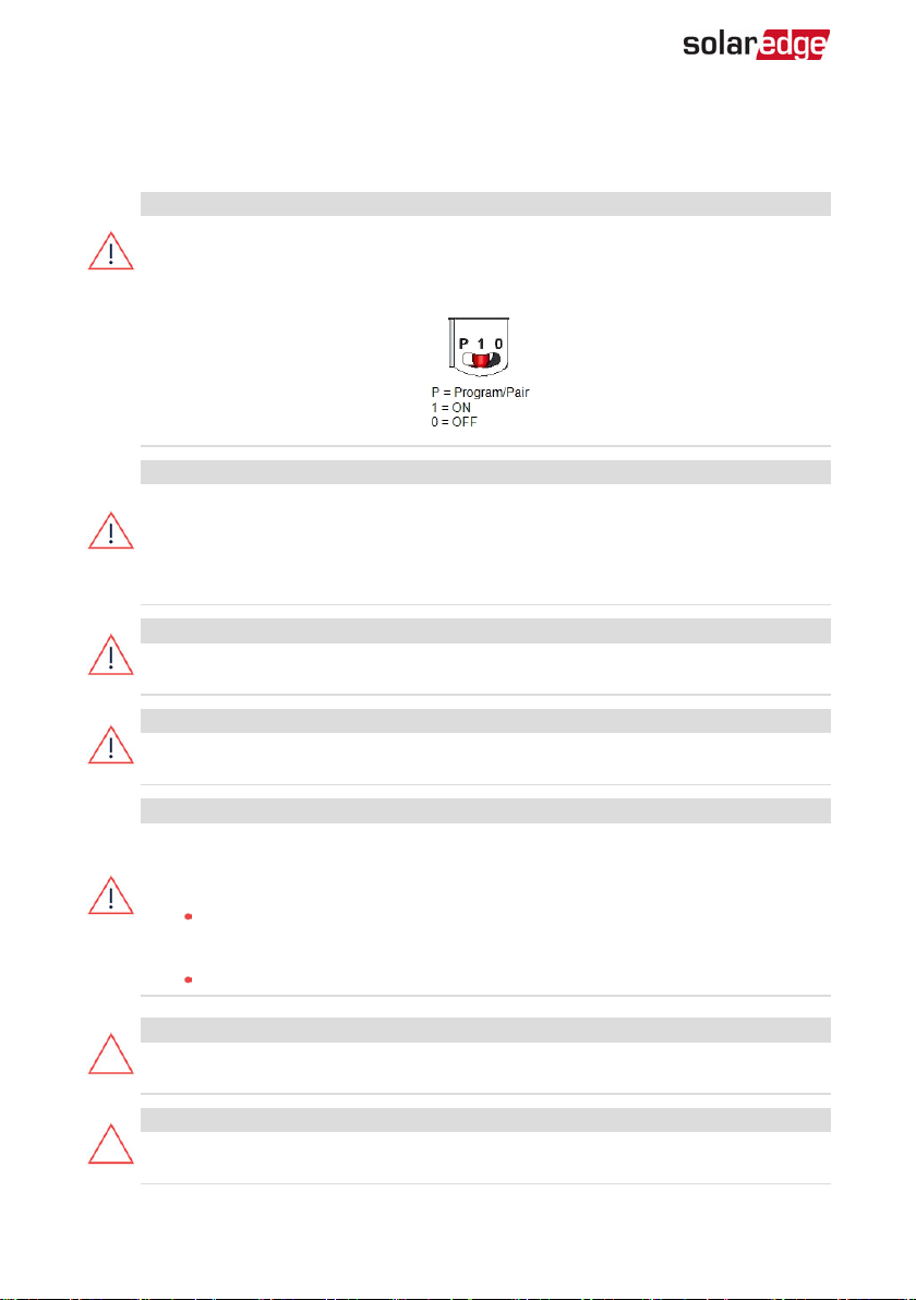
The inverter cover must be opened only after switching the inverter ON/OFF/P
switch located at the bottom of the inverter to OFF. This disables the DC voltage
inside the inverter. Wait five minutes before opening the cover. Otherwise, there
is a risk of electric shock from energy stored in the capacitors.
WARNING!
Before operating the inverter, ensure that the inverter AC power cable and wall
outlet are grounded properly. This product must be connected to a grounded,
metal, permanent wiring system, or an equipment-grounding conductor must
be run with the circuit conductors and connected to the equipment grounding
terminal or lead on the product.
WARNING!
Opening the inverter and repairing or testing under power must be performed
only by qualified service personnel familiar with this inverter.
WARNING!
Do not touch the PV panels or any rail system connected when the inverter
switch is ON, unless grounded.
WARNING!
SafeDC complies with IEC60947-3 when installing the system with a worst case
SafeDC voltage (under fault conditions) < 120V.
The worst case voltage is defined as: Voc,max+ (String Length-1)*1V, where:
Voc,max = Maximum Voc (at lowest temperature) of the PV module in
the string (for a string with multiple module models, use the max value)
String Length = number of power optimizers in the string
CAUTION!
This unit must be operated according to the technical specification datasheet
provided with the unit.
CAUTION!
HEAVY OBJECT. To avoid muscle strain or back injury, use proper lifting
techniques, and if required - a lifting aid.
-Three Phase System Installation Guide MAN-01-00505-1.2
Page 10
IMPORTANTSAFETYINSTRUCTIONS 9
NOTE
The inverter is IP65 rated . Unused conduit openings and glands should be
sealed with appropriate seals.
NOTE
Use PV modules rated according to IEC 61730 class A.
NOTE
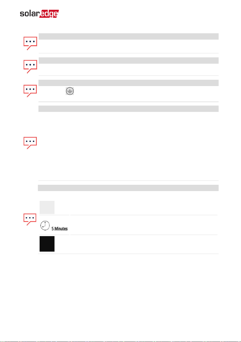
The symbol appears at grounding points on the SolarEdge equipment. This
symbol is also used in this manual.
NOTE
A SolarEdge inverter may be installed in a site with a generator, however must
not operate at the same time as the generator.
Operating an inverter and a generator simultaneously will void the warranty.
SolarEdge requires installing a physical or electronic interlock, which will
prevent the generator and inverter from operating simultaneously. Interlock
procurement, installation, maintenance and support are the responsibility of
the installer. Damage to the inverter due to incorrect interlock installation or
use of an interlock that is incompatible with the SolarEdge system will render
the SolarEdge warranty invalid.
NOTE
The following warning symbols appear on the inverter warning label:
Risk of electric shock
Risk of electric shock from energy stored in the capacitor. Do not
remove cover
until 5 minutes after disconnecting all sources of supply.
Hot surface – To reduce the risk of burns, do not touch.
Three Phase System Installation Guide MAN-01-00505-1.2
Page 11
10 Chapter 1: Introducing the SolarEdge Power Harvesting System
Chapter 1: Introducing the SolarEdge Power Harvesting System
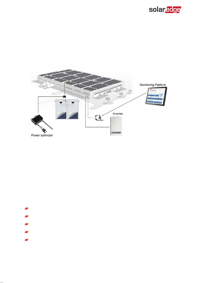
The SolarEdge power harvesting solution maximizes the power output from any type of
solar Photovoltaic (PV) installation while reducing the average cost per watt. The
following sections describe each of the system’s components.
Figure 1: The SolarEdge power harvesting system components
Power Optimiser
The power optimizers are DC-DC converters connected to PV modules in order to
maximize power harvesting by performing independent Maximum Power Point
Tracking (MPPT) at the module level.
The power optimizers regulate the string voltage at a constant level, regardless of string
length and environmental conditions.
The power optimizers include a safety voltage function that automatically reduces the
output of each power optimizer to 1 Vdc in the following cases:
During fault conditions
The power optimizers are disconnected from the inverter
The inverter ON/OFF switch is turned OFF
The safety switch on the DC Safety Unit is turned OFF
The inverter AC breaker is turned OFF
Each power optimizer also transmits module performance data over the DC power line
to the inverter.
-Three Phase System Installation Guide MAN-01-00505-1.2
Page 12
Chapter 1: Introducing the SolarEdge Power Harvesting System 11
Two types of power optimizers are available:
Module Add-on power optimizer – connected to one or more modules
Smart modules - the power optimizer is embedded into a module
Inverter
The inverter efficiently converts DC power from the modules into AC power that can be
fed into the main ACservice of the site and from there to the grid. The inverter also
receives the monitoring data from each power optimizer and transmits it to a central
server (the monitoring platform; requires Internet connection).
Some inverters are available with an optional DC Safety Unit. The DC Safety Unit has a
manually operated switch for disconnecting the DC power of a SolarEdge system.
The DC Safety Unit is located below the inverter and is connected to the inverter with
AC and DC wires.
Monitoring Platform
The monitoring platform enables monitoring the technical and financial performance of
one or more SolarEdge sites. It provides past and present information on the system
performance both at the system and module levels.
Installation Procedure
The following is the procedure for installing and setting up a new SolarEdge site. Many
of these also apply to modification of an existing site.
1. Connecting Power Optimizers in Strings, page 18.
2. Recording power optimizer serial numbers (optional), page 47.
3. Mounting the inverter, Page 25.
Connecting the AC and the Strings to the Inverter, page 31, or Connecting the AC and the
4.
String to the DCSafety Unit, page 68.
Commissioning and activating the installation, page 35.
5.
6. Connecting the inverter to the monitoring platform, page 48.
Installation Equipment List
Standard tools can be used during the installation of the SolarEdge system. The
following is a recommendation of the equipment needed for installation:
Allen screwdriver for 5mm screw type for the inverter cover, DC Safety Unit
cover (if applicable), and inverter side screws
Three Phase System Installation Guide MAN-01-00505-1.2
Page 13
12 Inverter Transport and Storage
Allen screwdriver for M5/M6/M8 screw types
Standard flat-head screwdrivers set
Non-contact voltage detector
Cordless drill (with a torque clutch)or screwdriver and bits suitable for the
surface on which the inverter and optimizers will be installed. Use of an impact
driver is
Appropriate mounting hardware (for example: stainless bolts, nuts, and
washers) for attaching:
MC4 crimper
Wire cutters
Wire strippers
Voltmeter
For installing the communication options, you may also need the following:
For Ethernet:
For RS485:
not
allowed.
the mounting brackets to the mounting surface
the power optimizer to the racking (not required for smart modules)
CAT5/6 twisted pair Ethernet cable with RJ45 connector.
If using a CAT5/6 cable spool: RJ45 plug and RJ45 crimper
Four- or six-wire shielded twisted pair cable.
Watchmaker precision screwdriver set
Inverter Transport and Storage
Transport the inverter in its original packaging, facing up and without exposing it to
unnecessary shocks. If the original package is no longer available, use a similar box that
can withstand the weight of the inverter (refer to the inverter weight in the specification
datasheet provided with the unit), has a handle system and can be closed fully.
Store the inverter in a dry place where ambient temperatures are -25°C to +65°C /
-13°F to 149°F.
-Three Phase System Installation Guide MAN-01-00505-1.2
Page 14
Chapter 2: Installing the Power Optimizers 13
Chapter 2: Installing the Power Optimizers
Safety
The following notes and warnings apply when installing the power optimizers. Some of
the following may not be applicable to smart modules:
WARNING!
When modifying an existing installation, turn OFF the inverter ON/OFF switch,
the Connection Unit and the AC circuit breaker on the main AC distribution
panel.
CAUTION!
Power optimizers are IP68/NEMA6P rated. Choose a mounting location where
optimizers will not be submerged in water.
CAUTION!
This unit must be operated according to the operating specifications provided
with the unit.
CAUTION!
Cutting the power optimizer input or output cable connector is prohibited and
will void the warranty.
CAUTION!
All PV modules must be connected to a power optimizer.
CAUTION!
If you intend to mount the optimizers directly to the module or module frame,
first consult the module manufacturer for guidance regarding the mounting
location and the impact, if any, on module warranty. Drilling holes in the
module frame should be done according to the module manufacturer
instructions.
Three Phase System Installation Guide MAN-01-00505-1.2
Page 15
14 Installation Guidelines
CAUTION!
Installing a SolarEdge system without ensuring compatibility of the module
connectors with the optimizer connectors may be unsafe and could cause
functionality problems such as ground faults, resulting in inverter shut down. To
ensure mechanical compatibility of the power optimizers’ connectors with the PV
modules’ connectors to which they are connected:
Use identical connectors from the same manufacturer and of the same
type on both the power optimizers and on the modules; or
Verify that the connectors are compatible in the following way:
The module connector manufacturer should explicitly verify
compatibility with the SolarEdge optimizer connector; and
A third-party test report by one of the listed external labs (TUV,
VDE, Bureau Veritas UL, CSA, InterTek) should be
obtained,verifying the compatibility of the
connectors.
For more information, refer to
https://www.solaredge.com/sites/default/files/optimizer-inputconnector-compatibility.pdf
IMPORTANTSAFETYFEATURE
Modules with SolarEdge power optimizers are safe. They carry only a low safety
voltage before the inverter is turned ON. As long as the power optimizers are
not connected to the inverter or the inverter is turned OFF, each power
optimizer will output a safe voltage of 1V.
Installation Guidelines
The minimum and maximum string length guidelines are stated in the power
optimizer datasheets. Refer to the Designer for string length verification. The
Designer is available on the SolarEdge website at
https://www.solaredge.com/products/installer-tools/designer#/.
Frame-mounted power optimizers are mounted directly on the
module frame , regardless of racking system (rail-less or with rails).
For installation of frame-mounted power optimizers, refer to
http://www.solaredge.com/sites/default/files/installing_frame_mounted_
power_optimizers.pdf.
-Three Phase System Installation Guide MAN-01-00505-1.2
Page 16
Chapter 2: Installing the Power Optimizers 15
The steps in this chapter refer to module add-on power optimizers. For smart
modules, start from
18
Step 3: Connecting Power Optimizers in Strings
Step 3: Connecting Power Optimizers in Strings
on page 18 Also refer to the
on page
documentation supplied with the smart modules.
The power optimizer can be placed in any orientation.
If connecting more modules than optimizer inputs in parallel, use a branch
cable. Some commercial power optimizer models have a dual input.
Position the power optimizer close enough to its module so that their cables
can be connected.
Make sure to use power optimizers that have the required output conductor
length:
Do not
use extension cables between a module and a power optimizer,
between two modules connected to the same optimizer, or between two
optimizers other than in the cases specified below.
You can use extension cables between power optimizers only from row
to row, around obstacles within a row, and from the end of the string to
the inverter, as long as the maximum distance is not exceeded.
NOTE
The total conductor length of the string (excluding
power optimizers’ conductors; including home runs and
necessary extensions between optimizers) should not
exceed the following:
Inverter model
Three phase up to
SE25K
Three phase SE25K
and above
Total conductor length ( from DC+
to DC- of the inverter)
1000 ft. /300 m
2300 ft./ 700 m
Use at least 11 AWG/ 4 mm² DC cables.
Completely shaded modules may cause their power optimizers to temporarily
shut down. This will not affect the performance of the other power optimizers in
the string, as long as the minimum number of unshaded power optimizers
connected in a string of modules is met. If under typical conditions fewer than
Three Phase System Installation Guide MAN-01-00505-1.2
Page 17
16 Installation Guidelines
the minimum optimizers are connected to unshaded modules, add more
optimizers to the string.
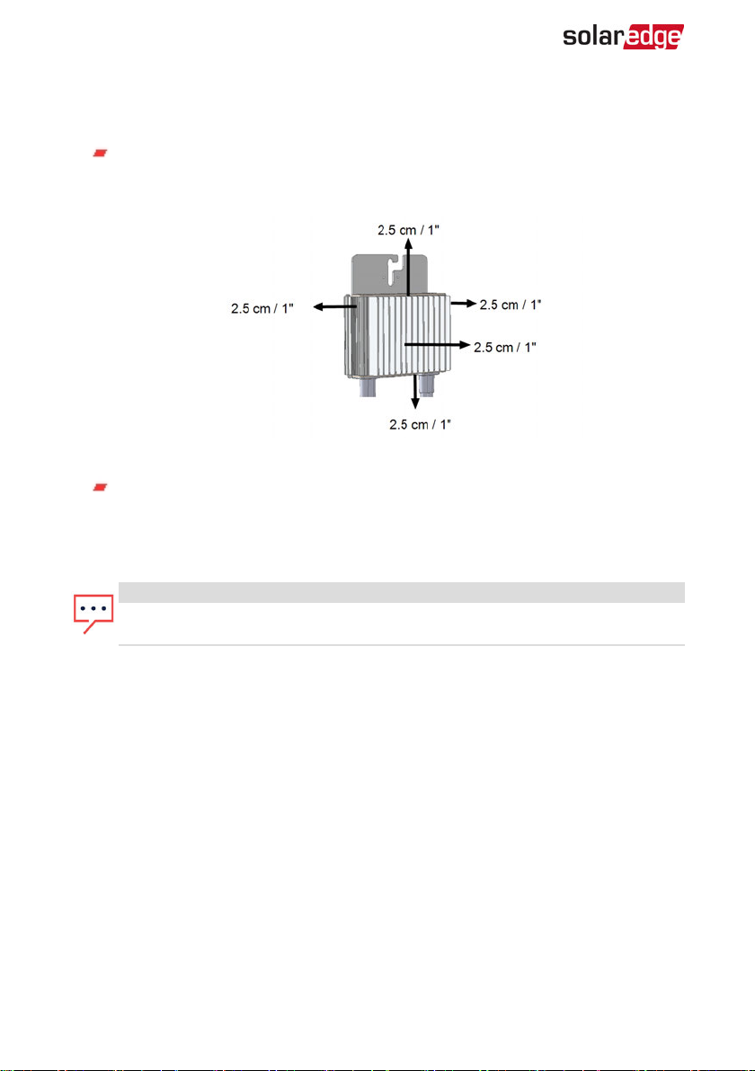
To allow for heat dissipation, maintain a 2.5 cm / 1" clearance distance between
the power optimizer and other surfaces, on all sides except the mounting
bracket side.
When installing modules in a confined space, for example, if installing Buildingintegrated photovoltaic (BIPV) modules, ventilation measures may be needed to
ensure the power optimizers are not be exposed to temperatures outside their
specifications.
Figure 2: Power optimizer clearance
NOTE
The images contained herein are for illustrative purposes only and may vary
depending on product models.
-Three Phase System Installation Guide MAN-01-00505-1.2
Page 18
Chapter 2: Installing the Power Optimizers 17
Step 1: Mounting the Power Optimizers
For each of the power optimizers
1. Determine the power optimizer mounting location and use the power
optimizer mounting brackets to attach the power optimizer to the
support structure . It is recommended to mount the power optimizer
in a location protected from direct sunlight. For frame-mounted
power optimizers follow the instructions supplied with the optimizers,
or refer to https://www.solaredge.com/sites/default/files/installing_frame_mounted_power_
optimizers.pdf.
If required, mark the mounting hole locations and drill the hole.
2.
CAUTION!
Drilling vibrations may damage the power optimizer and will void the
warranty. Use a torque wrench or an electric drill with adjustable clutch that
meets the mounting torque requirements.
mounting the power optimizer.
Do not
drill through the power optimizer or through the mounting holes.
Attach each power optimizer to the rack using M6 (1/4'') stainless steel bolts, nuts
3.
and washers or other appropriate mounting hardware. Apply torque of 9-10 N*m /
6.5-7 lb*ft.
4. Verify that each power optimizer is securely attached to the module support
structure.
5. Record power optimizer serial numbers and locations, as described in
Monitoring Installation Data
(1)
:
on page 46.
Do not
use impact drivers for
Reporting and
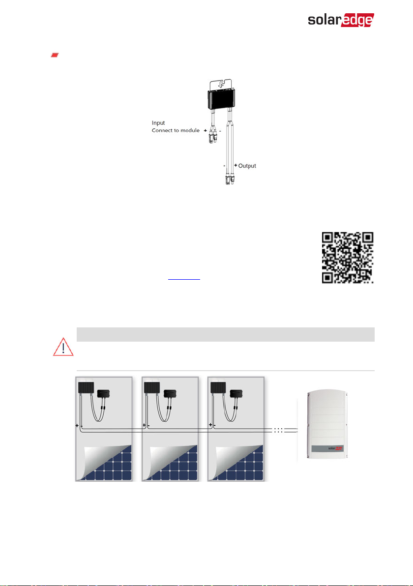
Step 2: Connecting a PV Module to a Power Optimiser
NOTE
Images are for illustration purposes only. Refer to the label on the product to
identify the plus and minus input and output connectors.
For each of the power optimizers:
Connect the Plus (+) output connector of the module to the Plus (+) input
connector of the power optimizer.
(1)
Not applicable to smart modules.
Three Phase System Installation Guide MAN-01-00505-1.2
Page 19
18 Step 3: Connecting Power Optimizers in Strings
Connect the Minus (-) output connector of the module to the Minus (-) input
connector of the power optimizer.
Figure 3: Power optimizer connectors
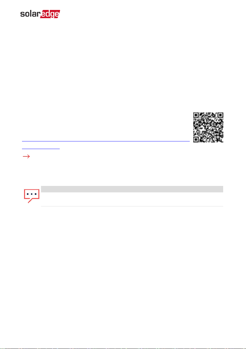
Step 3: Connecting Power Optimizers in Strings
You can construct parallel strings of unequal length, that is, the number
of power optimizers in each string does not have to be the same. The
minimum and maximum string lengths are specified in the power
optimizer datasheets. Refer to the Designer for string length verification.
1. Connect the Minus (-) output connector of the string’s first power optimizer to the
Plus (+) output connector of the string’s second power optimizer.
Connect the rest of the power optimizers in the string in the same manner.
2.
WARNING!
If using a dual-input power optimizer and some inputs are not used, seal the
unused input connectors with the supplied pair of seals.
Figure 4: Power optimizers connected in series
If you intend to monitor the installation, using the monitoring platform, record the
3.
physical location of each power optimizer, as described in
Physical Layout using Installation Information
-Three Phase System Installation Guide MAN-01-00505-1.2
on page 47.
Creating Logical and
Page 20
Chapter 2: Installing the Power Optimizers 19
Step 4: Verifying Proper Power Optimiser Connection
When a module is connected to a power optimizer, the power optimizer outputs a safe
voltage of 1V (±0.1V). Therefore, the total string voltage should equal 1V times the
number of power optimizers connected in series in the string. For example, if 10 power
optimizers are connected in a string, then 10V should be produced.
Make sure the PVmodules are exposed to sunlight during this process. The power
optimizer will only turn ON if the PVmodule provides at least 2W.
In SolarEdge systems, due to the introduction of poweroptimizers between the PV
modules and the inverter, the short circuit current ISC and the open circuit voltage VOC
hold different meanings from those in traditional systems.
For more information about the SolarEdge system’s string voltage and
current, refer to the
available on the SolarEdge website at:
https://www.solaredge.com/sites/default/files/isc_and_voc_in_solaredge_sytems_
technical_note.pdf .
To verify proper power optimizer connection:
Measure the voltage of each string individually before connecting it to the other strings
or to the inverter. Verify correct polarity by measuring the string polarity with a
voltmeter. Use a voltmeter with at least 0.1V measurement accuracy.
NOTE
Since the inverter is not yet operating, you may measure the string voltage and
verify correct polarity on the DC wires inside the DC Safety Unit.
VOC and ISC in SolarEdge Systems Technical Note
,
For troubleshooting power optimizer operation problems, refer to
Troubleshooting
Three Phase System Installation Guide MAN-01-00505-1.2
on page 65.
Power Optimizer
Page 21
20 Chapter 3: Installing the Inverter
Chapter 3: Installing the Inverter
Install the inverter either before or after the modules and power optimizers have been
installed.
CAUTION!
Do not rest the connectors at the bottom of the inverter on the ground, as it
may damage them. To rest the inverter on the ground, lay it on its back, front
or side.
Inverter Package Contents
One inverter with DC Safety Unit
One mounting bracket
Two Allen screws for fastening the inverter to the mounting bracket
Installation guide
Optional (for wireless communication to monitoring platform) - RF antenna and
mounting bracket
AC ferrite bead kit
Identifying the Inverter
Refer to the sticker on the inverter that specifies its Serial Number and its Electrical
Ratings. Provide the serial number when contacting SolarEdge support. The serial
number is also required when opening a new site in the monitoring platform.
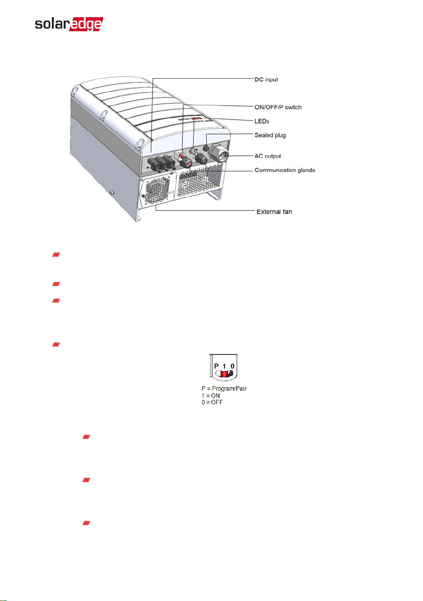
Inverter Interfaces
The following figure shows the inverter connectors and components, located at the
bottom of the inverter.
-Three Phase System Installation Guide MAN-01-00505-1.2
Page 22
Chapter 3: Installing the Inverter 21
Figure 5: Inverter Interfaces
ACoutput: ACoutput gland, AC cable external gauge, M32 (15-21mm diameter)
for connection to the grid
DC input: MC4 connector ,for connection of the PV installation
Two communication glands: for connection of inverter communication
options. Each gland has three openings. Refer to
Setting Up Communication
on
page 49 for more information.
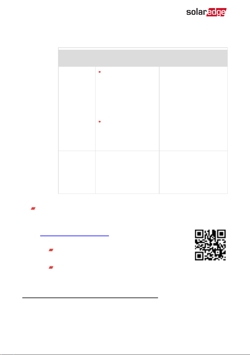
ON/OFF/P Switch:
Figure 6: ON/OFF/P switch
ON (1) - Turning this switch ON (after optimizer pairing) starts the
operation of the power optimizers, enables power production and
allows the inverter to begin exporting power to the utility grid.
OFF (0) - Turning this switch OFF reduces the power optimizer voltage
to a low safety voltage and inhibits exportation of power. When this
switch is OFF, the control circuitry remains powered up.
P - Moving and releasing the switch allows viewing system information
Three Phase System Installation Guide MAN-01-00505-1.2
Page 23
22 Inverter Interfaces
via the LEDs and on the SolarEdge SetApp mobile application screen,
and performing the following functions:
LEDs
P Position
duration
Function Comments
Displays (via
LEDs)production
While the switch is in P, all
LEDs are ON.
When the switch is released
all LEDs turn OFF for 0.5 sec
and then display the
production or error
indication.
Switch moved
to P for less
than 5
seconds, then
released.
information for 5
seconds, or error type
indications (if exist)
for 5 seconds.
Activates the Wi-Fi
access point for
connecting to the
SetApp
Switch moved
to P for more
than 5
seconds, then
Starts pairing
Pairing is indicated by all 3
LEDs blinking
simultaneously.
released.
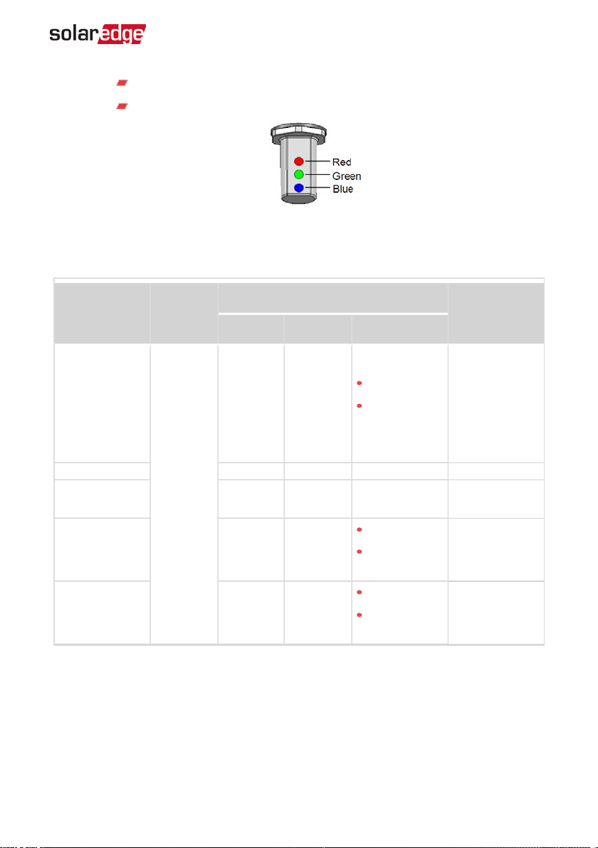
LEDs: three LEDs indicate, by color and state (on/ off/ blinking
flickering
(2)
/alternating
(3)
), different system information, such as errors or
performance indications.For more information, refer to
https://www.solaredge.com/leds.
The main LED indications are:
Blue ON - the inverter is communicating with the
monitoring platform
Green ON- the system is producing
(1)
/
(1)
Blinking = Turns ON and OFF for the same duration
(2)
Flickering = Turns ON for 100 mS and turns OFF for 5 seconds
(3)
Alternating = alternate LED flashes
-Three Phase System Installation Guide MAN-01-00505-1.2
Page 24
Chapter 3: Installing the Inverter 23
Green blinking - AC is connected but the system is not producing
Red ON - system error
Figure 7: LEDs
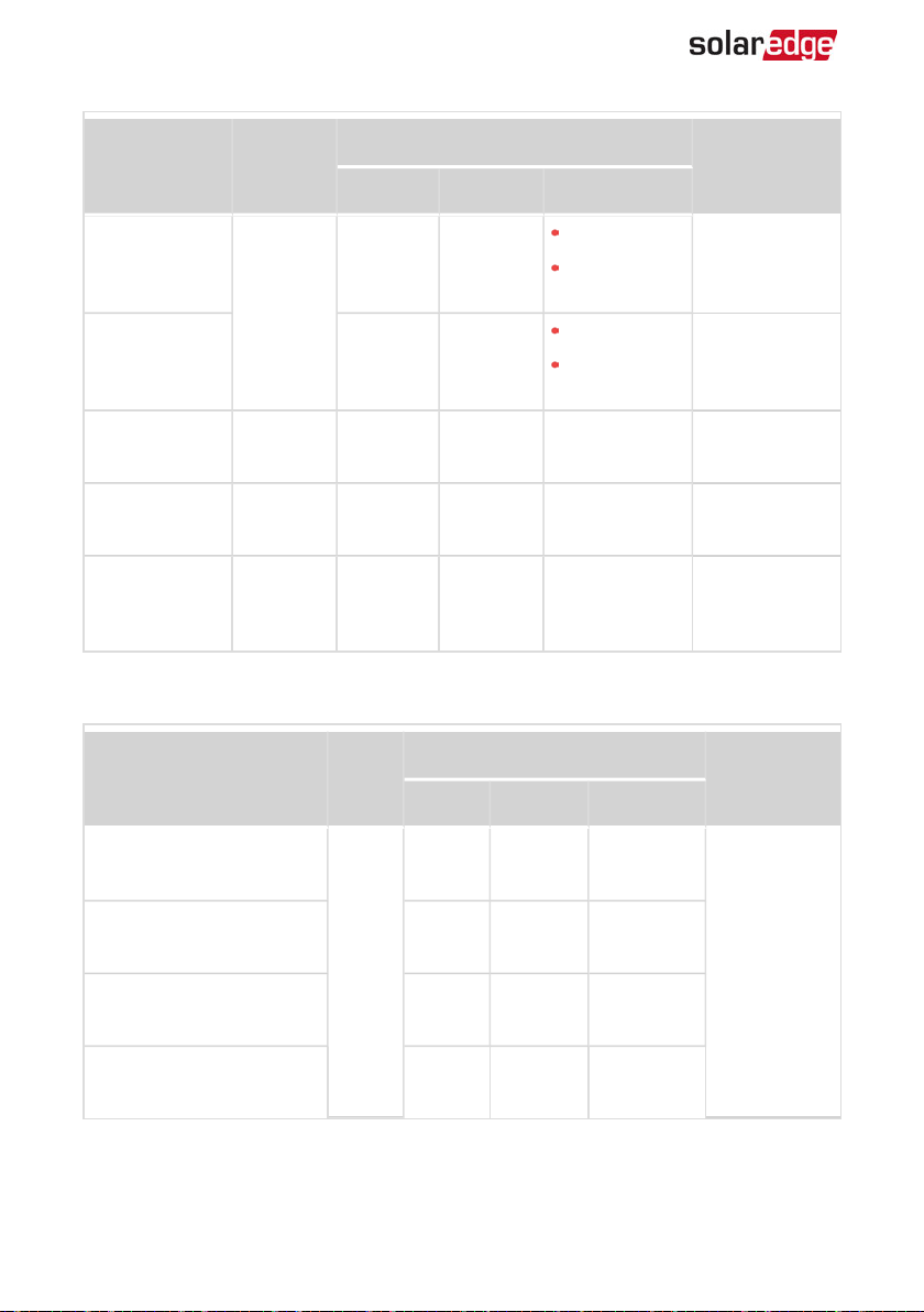
The following table describes system performance information by LED color and
ON/OFF/P switch position.
Indication
Power
optimizers not
paired
ON/ OFF/
P
switch
position
Red Green Blue
OFF Blinking
LEDcolor
S_OK: ON
No S_OK:
OFF
Pairing Blinking Blinking Blinking
Wake-up/ Grid
Monitoring
ON (1)
OFF Blinking Blinking
S_OK: ON
System
Producing
OFF ON
No S_OK:
OFF
S_OK: ON
Night mode
(no production)
OFF Flickering
No S_OK:
OFF
Comment
S_OK: ON
communication
with the
monitoring
platform is
established.
Three Phase System Installation Guide MAN-01-00505-1.2
Page 25
24 Inverter Interfaces
Indication
ON/ OFF/
P
switch
position
Red Green Blue
LEDcolor
Comment
S_OK: ON
Inverter is OFF
(Safe DC)
OFF (0)
OFF Blinking
No S_OK:
OFF
S_OK: ON
Inverter is OFF
(DC not safe)
Blinking Blinking
No S_OK:
OFF
Inverter
configuration
ON / P ON ON ON
or reboot
Inverter
firmware
ON / P Alternating Alternating Alternating
upgrade
Error Any ON
ON/ OFF/
Blinking/
Flickering
ON/ OFF /
Blinking
The upgrade
process can take
up to 5 minutes
Refer to
Errors
and
Troubleshooting
on page 62
The following table describes producution percentage of AC information by LED color
and ON/OFF/P switch position.
Indication
ON/
OFF/ P
switch
position
Red Green Blue
LEDcolor
Comment
Percentage of AC
Production:
OFF OFF OFF
0 %
Percentage of AC
Production:
0 - 33 %
Percentage of AC
Production:
33 - 66 %
OFF ON OFF
ON (1)
OFF OFF ON
This indicates
power
production as
percentage of
rated peak AC
output power
Percentage of AC
Production:
OFF ON ON
66 - 100 %
-Three Phase System Installation Guide MAN-01-00505-1.2
Page 26
Chapter 3: Installing the Inverter 25
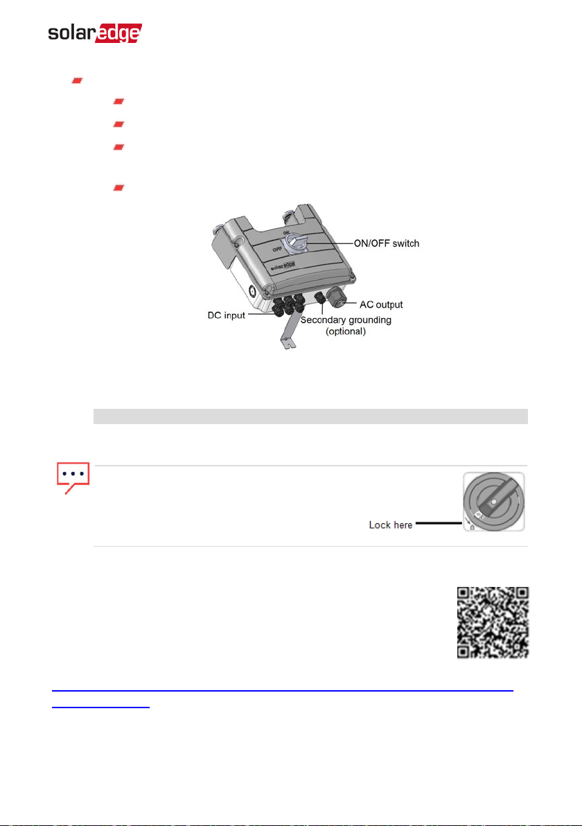
DC Safety Unit (if applicable), including:
ON/OFF switch: connects and disconnects the DC power of the system
AC output: Cable gland for connection to the grid
DC input: Cable glands or MC4 connectors for connection of the PV
installation
Secondary grounding (optional): Cable gland for grounding
Figure 8: DC Safety Unit
NOTE
When the DC Safety Unit is OFF (for example during maintenance) it may be
locked to prevent a safety hazard:
1. Move the switch to the Lock position.
2. Insert the lock through the knob opening
and lock.
Mounting the Inverter
The inverter is typically mounted vertically, and the instructions in this
section are applicable for vertical installation. Some three phase inverter
models can be installed horizontally (above 10° tilt) as well as vertically,
and at any tilt over 10° up to 90°. For information and instructions for
horizontal mounting refer to
http://www.solaredge.com/sites/default/files/application_note_horizontal_mounting_of_three_
phase_inverters.pdf.
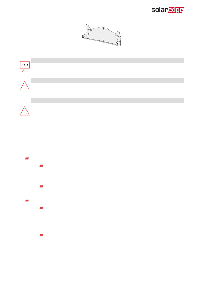
The inverter is supplied with a mounting bracket.
Three Phase System Installation Guide MAN-01-00505-1.2
Page 27
26 Mounting the Inverter
Figure 9: Mounting bracket
NOTE
Make sure the mounting surface or structure can support the weight of the
inverter and bracket, and make sure that it spans the width of the bracket.
CAUTION!
HEAVY OBJECT. To avoid muscle strain or back injury, use proper lifting
techniques, and if required - a lifting aid.
CAUTION!
SolarEdge inverters and power optimizers can be installed at a minimum
distance of 50 m/ 164 ft from the shoreline of an ocean or other saline
environment, as long as there are no direct salt water splashes on the inverter or
power optimizer.
1. Determine the inverter mounting location, on a wall, stud framing or pole. It is
recommended to mount the inverter in a location protected from direct sunlight.
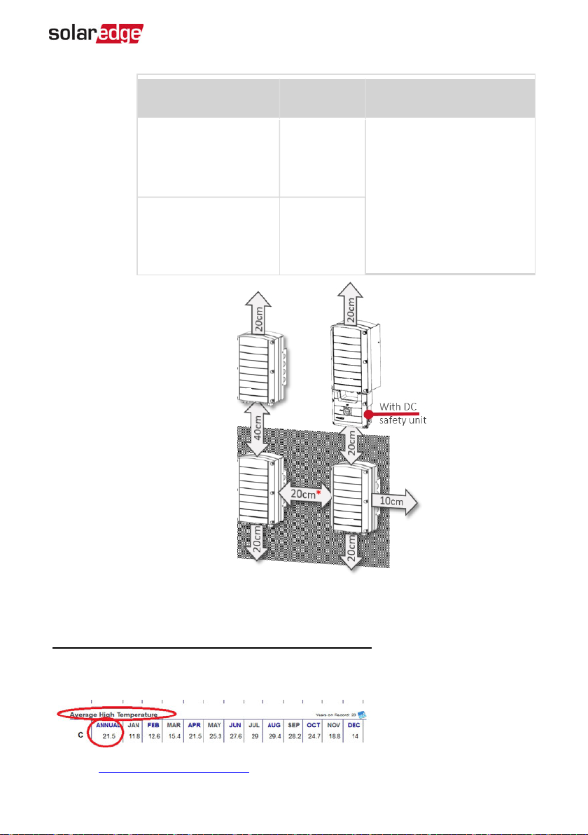
2. To allow proper heat dissipation, maintain the following minimum clearance areas
between the inverter and other objects:
If installing a single inverter:
At least 20 cm (8") from the top and bottom of the inverter; if installing
an inverter with a DC Safety Unit, make sure to leave sufficient clearance
for cable entry.
10 cm (4") from the right and left of the inverter. For easy access to the
fans , a larger clearance is recommended.
If installing multiple inverters:
When installing inverters one above the other, leave at least 40 cm (16")
between inverters. If installing an inverter with a DC Safety Unit, leave 20
cm (8") between the top of an inverter and the bottom of the DC Safety
Unit).
When installing inverters side by side, follow these clearance
specifications:
-Three Phase System Installation Guide MAN-01-00505-1.2
Page 28
Chapter 3: Installing the Inverter 27
Location
Locations where the
annual average high
temperature
(1)
is below
25˚C / 77˚F
Locations where the
annual average high
temperature1 is above
25˚C / 77˚F
Indoor
Installation
20 cm / 8"
between
inverters
40 cm / 16"
between
inverters
Outdoor Installation
5 cm / 2" between inverters (if
inverters are also installed one
above the other, maintain the
indoor installation clearance)
Figure 10: Clearance
(1)
Annual average high temperature – the average of the 12 monthly average highs, for
example:
Refer to http://www.weatherbase.com/ to find the value in your location.
Three Phase System Installation Guide MAN-01-00505-1.2
Page 29
28 Mounting the Inverter
3. Position the mounting bracket against the wall/pole and mark the drilling hole
locations (refer to
Mechanical Specifications
on page 67 for inverter and mounting
bracket dimensions):
Ensure that the flat edge of the bracket is at the bottom, as in
Figure 11
.
Use at least two bracket holes. Additional holes can be used to fix the
bracket. Determine which and how many holes to use according to
mounting surface type and material.
4. Drill the holes and mount the bracket. Verify that the bracket is firmly attached to
the mounting surface.
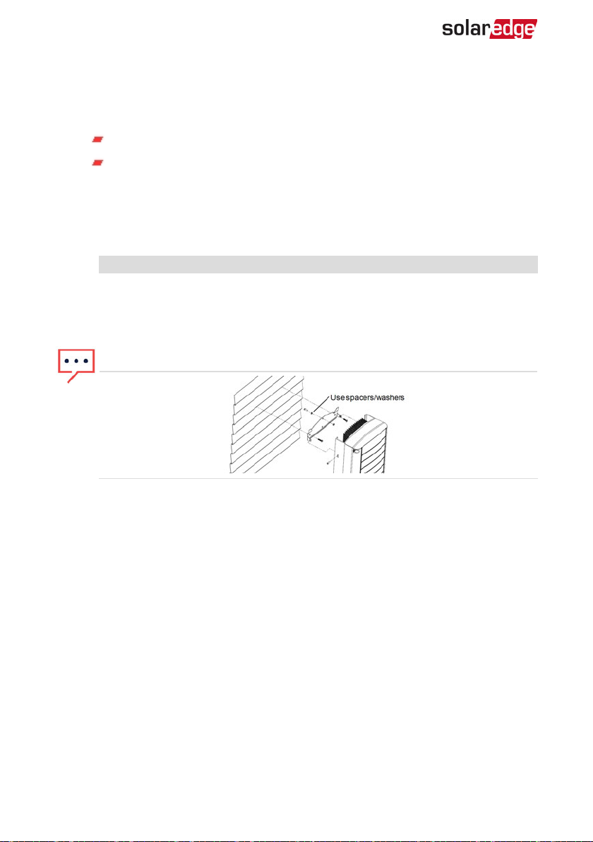
NOTE
When mounting an inverter on an uneven surface, you may use spacers/
washers behind the top mounting hole of the bracket. Depending on the
angle, use the appropriate size and number of spacers so that the bracket is
perpendicular to the ground. Recommended: a stainless steel 3/4" long screw,
with a 1/4" socket button head , two jam nuts and three washers.
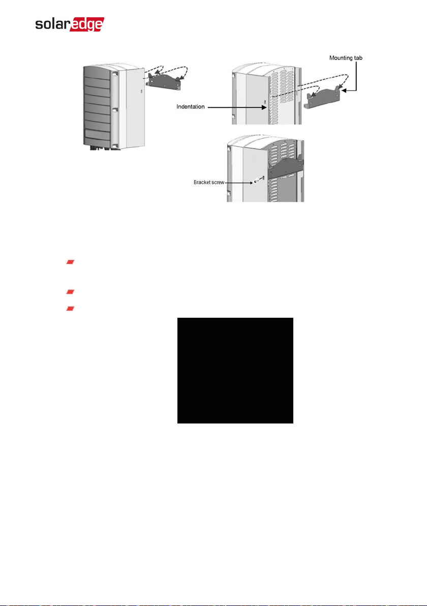
5. Hang the inverter on the bracket (see
Figure 11
): Lift the inverter from the sides, or
hold it at the top and bottom of the inverter to lift the unit into place. Do not lift
holding the Connection UnitDC Safety Unit as it may be damaged.
Align the two indentations in the inverter enclosure with the two triangular
6.
mounting tabs of the bracket, and lower the inverter until it rests on the bracket
evenly.
-Three Phase System Installation Guide MAN-01-00505-1.2
Page 30
Chapter 3: Installing the Inverter 29
Figure 11: Hanging the inverter on the bracket
7. Secure the Connection Unit bracket to the wall:
8. For inverters with Connection Unit - secure the Connection Unit bracket to the wall:
Mark the location of the bracket screw for the DC Safety Unit and drill the
hole.
Fasten the bracket using a standard bolt.
Verify that the bracket is firmly attached to the mounting surface.
Figure 12: DC Safety Unit bracket
9. Insert the two supplied screws through the outer heat sink fin on both sides of the
inverter and into the bracket (see
Figure 11
). Tighten the screws with a torque of 4.0
N*m / 2.9 lb.*ft.
Three Phase System Installation Guide MAN-01-00505-1.2
Page 31
30 Chapter 4: Connecting the AC and the Strings to the Inverter
Chapter 4: Connecting the AC and the Strings to the Inverter
This chapter describes how to connect the inverter to the AC grid, and to the strings of
modules with power optimizers.
If using an inverter with a DC Safety Unit, refer to the instructions in
and DCStrings to the DC Safety Unit
Refer to the technical specifications provided with the inverter.
on page 68.
Grid Connection Guidelines
In most countries, three phase inverters require neutral connection at all times.
In some countries, the three phase inverters can be connected to delta grids; in
other cases, multiple single phase inverters can be used.
Prior to system installation, refer to:
Three Phase Inverters for Delta Grids application note at
https://www.solaredge.com/sites/default/files/se_three_phase_
inverters_for_delta_grids.pdf
Connecting the AC
Supported Countries application note to confirm compatibility at
http://www.solaredge.com/sites/default/files/se_inverters_
supported_countries.pdf; installing without confirmation
may void the inverter warranty.
For more wiring information refer to the
Recommended AC Wiring Application Note
SolarEdge website at http://www.solaredge.com/files/pdfs/application-
note-recommended-wiring.pdf.
For recommended circuit breaker size per model refer to
Determining the Circuit Breaker Size
-Three Phase System Installation Guide MAN-01-00505-1.2
SolarEdge
, available on the
on page 82
Page 32
Chapter 4: Connecting the AC and the Strings to the Inverter 31
Connecting the ACGrid to the Inverter
Use a five-wire cable for three phase connection. The maximum wire size for the input
terminal blocks is 16mm².
1. Turn OFF the AC circuit breaker.
2. Open the inverter cover: Release the six Allen screws and carefully move the cover
horizontally before lowering it.
CAUTION!
When removing the cover, make sure not to damage internal components.
SolarEdge will not be held responsible for any components damaged as a
result of incautious cover removal.
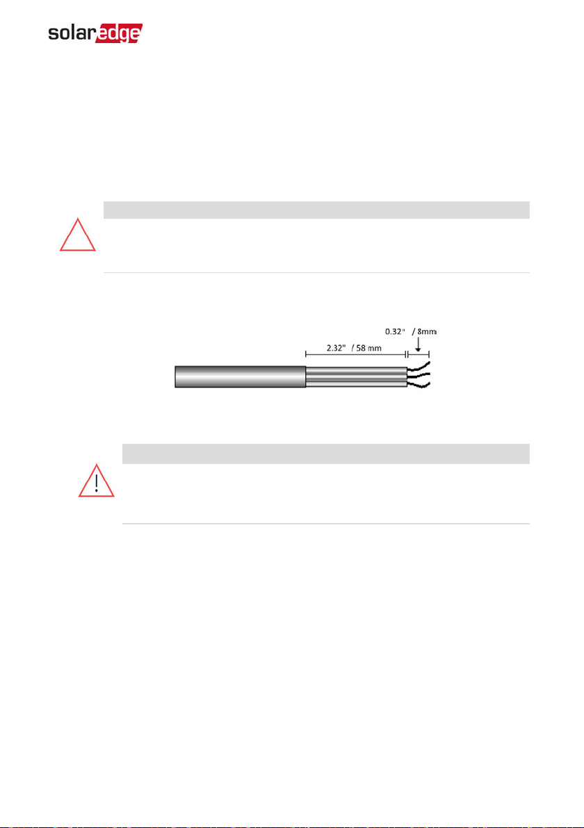
Strip 58 mm / 2.32'' of the external cable insulation and strip 8 mm / 0.32'' of the
3.
internal wire insulation.
Figure 13: Insulation stripping – AC (3-wire cable)
Open the AC cable gland and insert the cable through the gland (see
4.
Figure 5
).
WARNING!
Turn OFF the AC before connecting the AC terminals. If connecting
equipment grounding wire, connect it before connecting the AC Line and
Neutral wires.
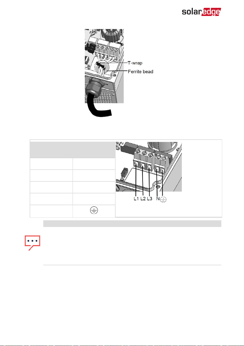
For SE25K, SE27.6K, and SE33.3K three phase inverters, attach the supplied Ferrite
5.
bead to the AC wires:
1. Insert the AC wires through the supplied bead.
2. Connect the AC wires to the terminal blocks as described in the next steps.
3. Tighten the wires to the bead using the supplied T-wrap.
Three Phase System Installation Guide MAN-01-00505-1.2
Page 33
32 Connecting the ACGrid to the Inverter
Figure 14: Attaching a Ferrite bead
Connect the AC, as follows. Connect the PE (grounding) wire first.
6.
Wire type
Connect to
terminal
Line 1 L1
Line 2 L2
Line 3 L3
Neutral N
PE (grounding)
Figure 15: AC Terminals
NOTE
If power control is enabled, it is important to respect the order of grid lines
connection to the inverter. A 120deg phase difference should be kept
between L1 to L2 and between L2 to L3 (L1-L2-L3 and not, for example L1-L3L2).
If the grid lines are not in this order, an error is displayed on the SetApp
screen and the inverter will not produce power.
7. Connect the wires to the appropriate terminal block connectors in the inverter.
Tighten the terminal block screws with a torque of 1.2-1.5 N*m / 0.88-1.1 lb*ft.
8. Check that the wires are fully inserted and cannot be pulled out easily.
9. Tighten the AC cable gland with a torque of 2.8-3.3 N*m / 2.0-2.4 lb*ft.
10. Verify that there are no unconnected wires to the inverter and that the unused
terminal screws are tightened.
-Three Phase System Installation Guide MAN-01-00505-1.2
Page 34
Chapter 4: Connecting the AC and the Strings to the Inverter 33
Connecting the Strings to the Inverter
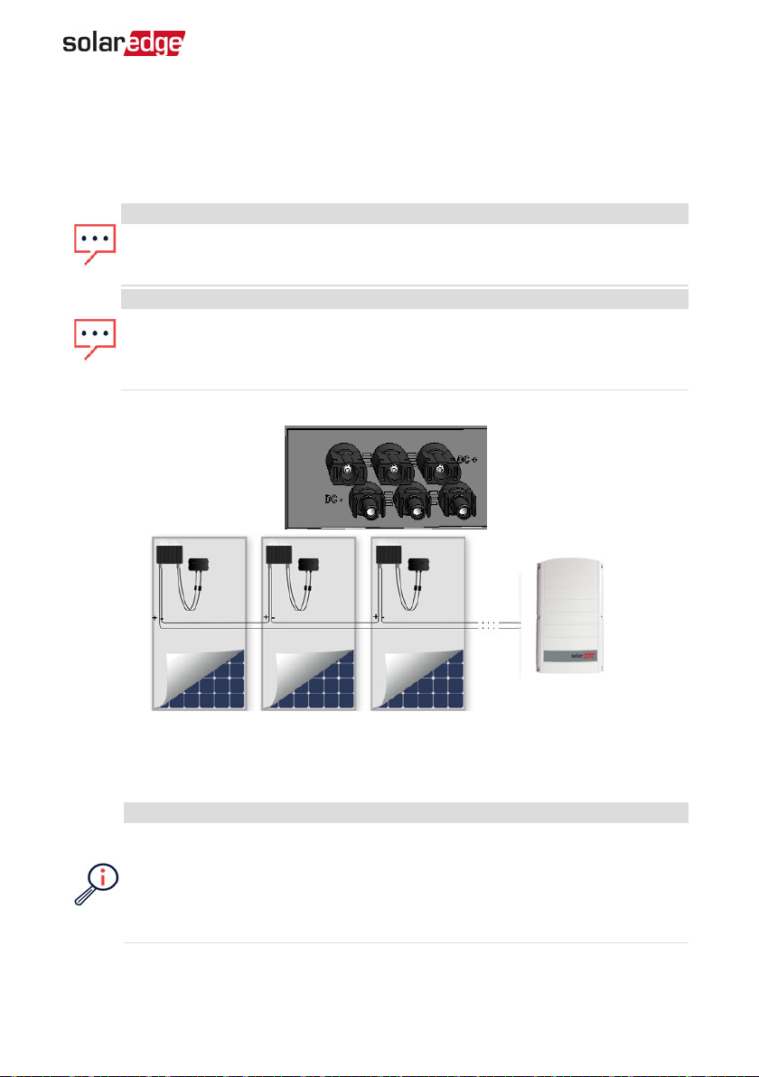
Connect the string to the DC input pairs. If required, connect additional strings in
parallel using an external combiner box/branch cables before connecting to the
inverter.
NOTE
Functional electrical earthing of DC-side negative or positive poles is prohibited
because the inverter has no transformer. Grounding (earth ground) of module
frames and mounting equipment of the PV array modules is acceptable.
NOTE
SolarEdge’s fixed input voltage architecture enables the parallel strings to be of
different lengths. Therefore, they do not need to have the same number of
power optimizers, as long as the length of each string is within the permitted
range.
Connect the DC connectors of each string to the DC+ and DC- connectors .
Figure 16: Inverter DC Connections
Selecting a Residual Current Device (RCD)
IMPORTANTSAFETYFEATURE
All SolarEdge inverters incorporate a certified internal Residual Current Device
(RCD) in order to protect against possible electrocution and fire hazard in case
of a malfunction in the PV array, cables or inverter. There are 2 trip thresholds
for the RCD as required for certification (DIN VDE 0126-1-1). The default value
for electrocution protection is 30 mA, and for slow rising current is 300 mA.
Three Phase System Installation Guide MAN-01-00505-1.2
Page 35
34 Selecting a Residual Current Device (RCD)
If an external RCD is required by local regulations, check which type of RCD is required
for the relevant electric code. Install the residual-current device (RCD) in accordance
with the applicable local standards and directives. SolarEdge recommends using a typeA RCD. The recommended RCD value is 100 mA or 300 mA unless a lower value is
required by the specific local electric codes. For extended power three phase inverters
(SE25K, SE27.6K and SE33.3K) an RCD value of 300 mA should be used. When required
by local regulations, the use of an RCD type B is permitted.
NOTE
For multiple inverters, an RCD per inverter is required.
In installations where the local electric code requires an RCD with a lower leakage
setting, the discharge current might result in nuisance tripping of the external RCD. The
following steps are recommended to avoid nuisance tripping of the external RCD:
Select the appropriate RCD for correct operation of the installation: An RCD with
a rating of 30 mA may actually trip at a leakage as low as 15 mA (according to
IEC 61008). High quality RCDs will typically trip at a value closer to their rating.
Configure the trip voltage of the inverter's internal RCD to a lower value than
the trip current of the external RCD. The internal RCD will trip if the current is
higher than the allowed current, but because the internal inverter RCD
automatically resets when the residual currents are low it saves the manual
reset.
For detailed information, refer to the
Inverters Application Note
http://www.solaredge.com/sites/default/files/application_note_ground_fault_
rcd.pdf.
, available on the SolarEdge website at
RCD Selection for SolarEdge
-Three Phase System Installation Guide MAN-01-00505-1.2
Page 36
Chapter 5: Activating, Commissioning and Configuring the System Using the
Inverter SetApp 35
Chapter 5: Activating, Commissioning and Configuring the System Using the Inverter SetApp
If applicable, you can connect communication options at this stage, as described in
Setting Up Communication
Once all connections are made, the system should be activated and commissioned
using the Inverter SetApp mobile application. You can download the app from the
Apple App Store and Google Play prior to reaching the site.
on page 49.
Internet connection is required for the download and for the one-time registration,
however not required for using the SetApp.
Step 1: Activating the Installation
During system activation, a Wi-Fi connection is created between the mobile device and
the inverter and the system firmware is upgraded.
Before activation - download, register (first time only)and log-in to SetApp on your
mobile device. Internet connection is required for the download and for the one-time
registration. Verify that the application is updated with the latest version.
To activate the inverter:
1. Turn ONthe ACcircuit breaker on the main distribution panel.
2. Open SetApp and follow the instructions on the screen (scan the inverter bar-code;
move the ON/OFF/P switch to P position and release within 5 sec. back to ON(1)
position). SetApp creates a Wi-Fi connection, upgrades the inverter CPUfirmware
and activates the inverter.
Three Phase System Installation Guide MAN-01-00505-1.2
Page 37
36 Step 2: Commissioning and Configuring the Installation
3. When the activation is complete, do one of the following:
Select Activate Another Inverter to continue activating additional inverters
Select Start Commissioning for pairing and other system configuration. The
Commissioning screen is displayed. Refer to the next section for more
information.
Step 2: Commissioning and Configuring the Installation
This section describes how to use the SetApp menus for commissioning and
configuring the inverter settings.
Menus may vary in your application depending on your system type.
To access the Commissioning screen:
Do one of the following:
During first time installation: Upon Activation completion, in the SetApp, tap
Start Commissioning. The main Commissioning menu screen is displayed.
If the inverter has already been activated and commissioned:
If not already ON - turn ON AC to the inverter by turning ON the circuit
breaker on the main distribution panel.
Open SetApp and follow the instructions on the screen (scan the inverter
bar-code; move the ON/OFF/P switch to P position (for less than 5 sec) and
release).
The mobile device creates a Wi-Fi connection with the inverter and displays
the main Commissioning screen.
In the main menus, tap the menu red arrows (›)to perform the system commissioning
or configuration task. Tap the Back arrow (‹) to return to the previous menu.
The next sections provide more information about configuration options (in addition to
Country and Language and Pairing, described in
Configuring the Installation
on page 36).
Step 2: Commissioning and
Setting Country and Language
From the Commissioning screen select Country and Language .
1.
From the Country drop-down list, select the required country setting.
2.
-Three Phase System Installation Guide MAN-01-00505-1.2
Page 38
Chapter 5: Activating, Commissioning and Configuring the System Using the
Inverter SetApp 37
WARNING!
The inverter must be configured to the proper setting in order to ensure that
it complies with the country grid code and functions properly with the
country grids.
3. From the Language drop-down list, select the language.
4. Tap Set Language.
Pairing
From the main menu, select Pairing.
1.
2. Tap Start Pairing.
When Pairing Complete is displayed, the system startup process begins:
3.
Since the inverter is ON, the power optimizers start producing power and the
inverter starts converting AC.
WARNING!
When you turn ON the inverter ON/OFF/P switch, the DC cables carry a high
voltage and the power optimizers no longer output a safe 1V output.
When the inverter starts converting power after the initial connection to the AC, the
inverter enters Wakeup mode until its working voltage is reached. This mode is
indicated by the flickering green inverter LED.
When working voltage is reached, the inverter enters Production mode and
produces power. The steadily lit green inverter LED indicates this mode.
4. Tap OK to return to the main menu.
Communication
Communication settings can be configured only after communication connections are
complete. Refer to
Select the Communication menu to define and configure the following:
1.
The communication option used by the inverter to communicate with the
monitoring platform
The communication option used to communicate between multiple
SolarEdge devices or other external non-SolarEdge devices, such as
electricity meters or loggers.
Tap the Server red arrow to set the communication method to be used for
2.
Three Phase System Installation Guide MAN-01-00505-1.2
Setting Up Communication
on page 49.
Page 39
38 Step 2: Commissioning and Configuring the Installation
communication between devices and the SolarEdge monitoring platform. The
default is LAN.
NOTE
The Server menu shows only the communication options installed in the
inverter.
For detailed information about all the configuration options, refer to the
Communication Options Application Note
website at https://www.solaredge.com/sites/default/files/solaredge-
communication_options_application_note_v2_250_and_above.pdf.
, available on the SolarEdge
Power Control
Power control options are detailed in the
Note
, available on the SolarEdge website at
https://www.solaredge.com/sites/default/files/application_note_power_control_
configuration.pdf.
The Grid Control option may be disabled. Enabling it opens additional options in the
menu.
The Energy Manager option is used for setting power export limitation, as
described in the
SolarEdge website at https://www.solaredge.com/sites/default/files/feed-in_
limitation_application_note.pdf.
Export Limitation Application Note
Power Control Application
, available on the
Device Manager
From the Commissioning menu, select Device Manager to configure various system
Smart Energy Management devices.
For more information refer to https://www.solaredge.com/products/device-
control#/.
Maintenance
From the Commissioning menu, select Maintenance to configure various
system settings, as described below.
-Three Phase System Installation Guide MAN-01-00505-1.2
Page 40
Chapter 5: Activating, Commissioning and Configuring the System Using the
Inverter SetApp 39
Date and Time: Set the internal real-time clock. If connected to the monitoring
platform, the date and time are set automatically and only time zone should be
set.
Reset Counters: Resets the accumulated energy counters that are sent to the
monitoring platform
Factory Reset: Performs a general reset to the default device settings.
Arc Fault Circuit Interrupter (AFCI): Enables or disables production interruption
in case of arc-fault, sets the reconnection mode, and enables or disables manual
AFCIself-test.
Refer to https://www.solaredge.com/sites/default/files/arc_fault_
detection_application_note.pdf .
Firmware Upgrade: Perform a software upgrade.
Diagnostics: Displays the Isolation status and power optimizer
status screens. Refer to
https://www.solaredge.com/sites/default/files/application_note_
isolation_fault_troubleshooting.pdf.
Activate Standby Mode: Enables/disables Standby Mode - for
remote commissioning.
Grid Protection: Available in specific countries. Enables viewing and setting grid
protection values.
Board Replacement: Backs up and restores the system parameters, including
energy counters; Used during board replacement according to the instructions
supplied with replacement kits.
Information
From the Commissioning menu, select Information to view and set various system
settings, as described below.
CPU Version: The communication board firmware version
DSP 1/2 Version: The digital board firmware version
NOTE
Please have these numbers ready when you contact SolarEdge Support.
Serial Number - The inverter serial number as appears on the enclosure sticker
Three Phase System Installation Guide MAN-01-00505-1.2
Page 41
40 Step 3: Verifying Proper Activation and Commissioning
Hardware IDs: Displays the following HW serial numbers (if exist, and
connected to the inverter):
This inverter: the inverter's ID
Meter # : Energy meter ID (up to 3 meters can be connected)
ZB: ZigBee Plug-in MAC address
WiFi: Wi-Fi MAC address
Error Log: Displays the last five errors, and enables resetting (clearing) the log.
Warning Log: Displays the last five warnings, and enables resetting (clearing)
the log.
Step 3: Verifying Proper Activation and Commissioning
1. Select Information and verify that the correct firmware versions are installed on each
inverter.
2. Select Status and verify that inverter is operating and producing power (see also
Viewing System Status
3. Verify that additional configurations were properly set by viewing the relevant
Status screens.
4. Verify that the green inverter LEDis steadily lit.
Your SolarEdge power harvesting system is now operational.
on page 40).
Viewing System Status
During normal operation, the Status screen displays all the inverter settings and
operation status. Scroll up or down to display various status parameters as described in
the following sections.
The LED indication provides more information about system performance; Refer to
on page 22.
To access the Status screen:
From the Commissioning menu select Status. The main inverter Status screen is
displayed (see below).
A red or orange icon (for example: ) may appear at the top left corner of a status cell,
indicating an error. The color indicates error severity (red is top severity). The error
description or information appears on the screen. Tap the error line for more
information and troubleshooting instructions, and refer to
on page 62.
-Three Phase System Installation Guide MAN-01-00505-1.2
Errors and Troubleshooting
LEDs
Page 42
Chapter 5: Activating, Commissioning and Configuring the System Using the
Inverter SetApp 41
A gray clock icon ( ) may appear at the top left corner of a status cell, indicating a
temporary status, such as a connection process. When the process is complete, the icon
disappears and a constant status message is displayed.
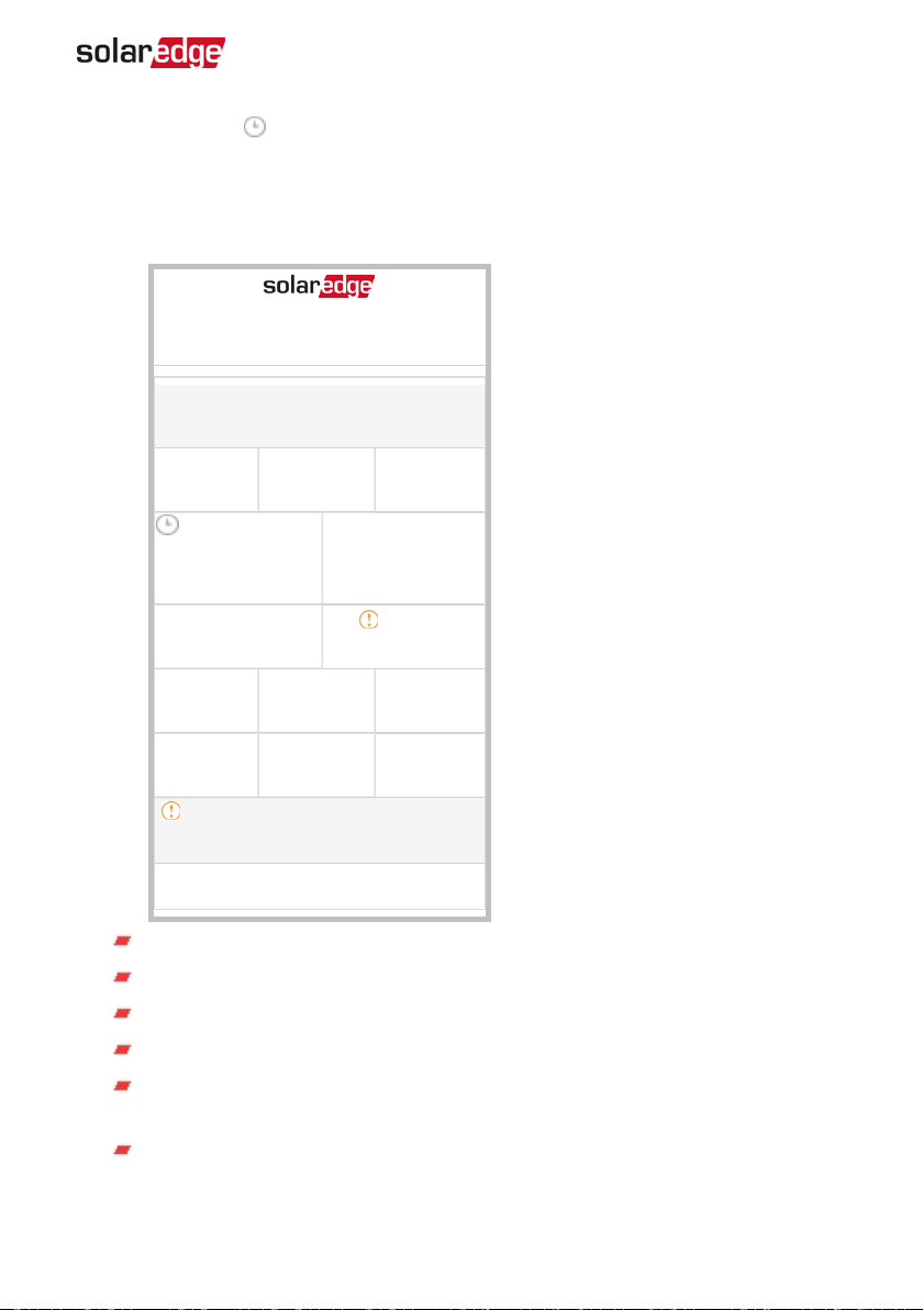
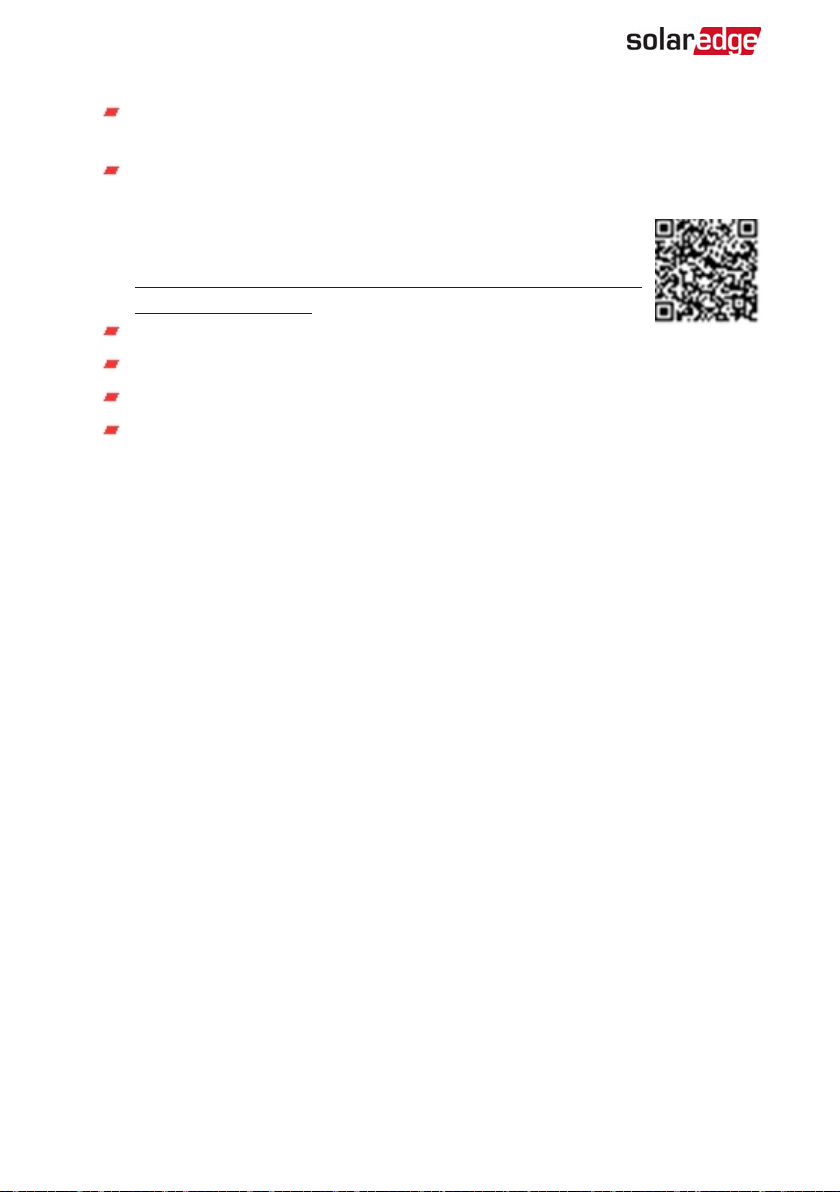
Main Inverter Status
Status
Inverter
SN 07318000C
Power
50 kW
P_OK: 15 of 20
Optimizers
Connected
Status
Production
CosPhi
1.00
Voltage
350 Vdc
Switch Off. Production disabled›
Voltage
230Vac
Limit
No Limit
Temp
20 C
Frequency
50 Hz
Server Comm.
S_OK
(LAN)
Switch
OFF
Country
Netherlands
Fan
N/A
Commissioning›
Inverter: The inverter serial number
Power: The AC output power
Voltage (Vac): The AC output voltage
Frequency: The AC output frequency
S_OK:The connection to the monitoring platform. (Server Connected appears
only if the inverter is connected to the monitoring platform).
Status: The inverter operation status:Off, Not Paired, Night Mode, Error,
Pairing, or Production
Three Phase System Installation Guide MAN-01-00505-1.2
Page 43
42 Viewing System Status
Switch: Indicates the position of the inverter ON/OFF/P switch: On, Off, or P
position.
CosPhi: Indicates the ratio between active and reactive power.A negative value
indicates a lagging CosPhi.
For more information, refer to the
Note
, available on the SolarEdge website at
https://www.solaredge.com/sites/default/files/application_note_power_
control_configuration.pdf.
Power Control Application
Limit: The inverter maximum output power
Country: The selected country and grid setting
Voltage (Vdc): The DC input voltage
Temp (°C or °F): The inverter heat sink temperature
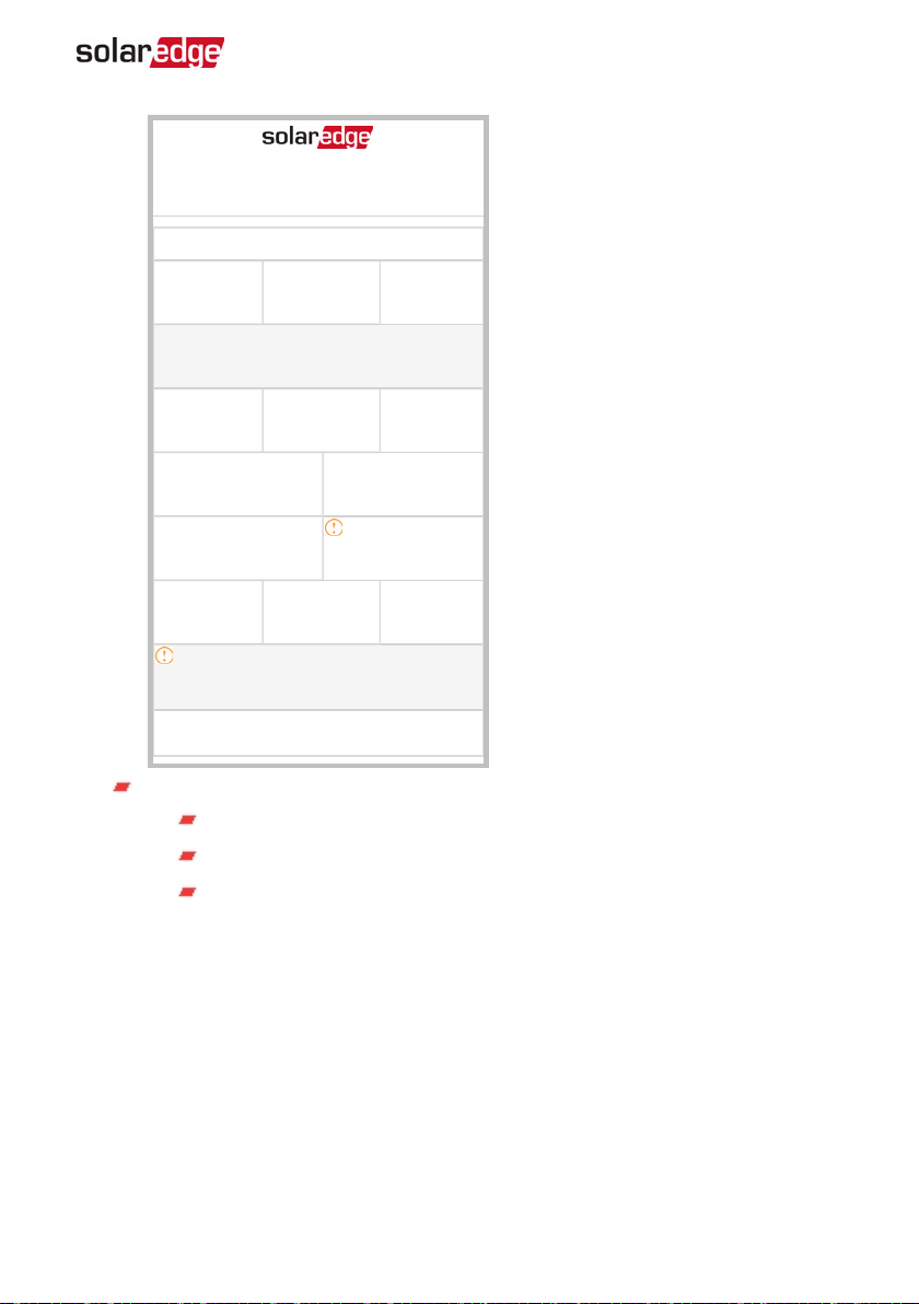
Site Status
The Site status screen shows the accumulated status of all inverters connected to a
master inverter in a chain (bus) and the master inverter status.
-Three Phase System Installation Guide MAN-01-00505-1.2
Page 44
Chapter 5: Activating, Commissioning and Configuring the System Using the
Status
Site
Production
90 kW
Power
100 kW
P_OK: 31 0f 31
Optimizers Connected
Status
Production
CosPhi
1.00
Switch Off. Production disabled›
Limit
1.00 MW
Inverter
SN 07318000C
Voltage
277 Vac
Server Connected
Limit
Export
Inverters
10/10
Frequency
60.9 Hz
S_OK
Switch
OFF
Country
ITA
Inverter SetApp 43
Commissioning›
Site status:
Production: The AC output power
Limit: Limitation setting (Export or Production)
Inverters: Number of connected inverters in the cluster, including the
master.
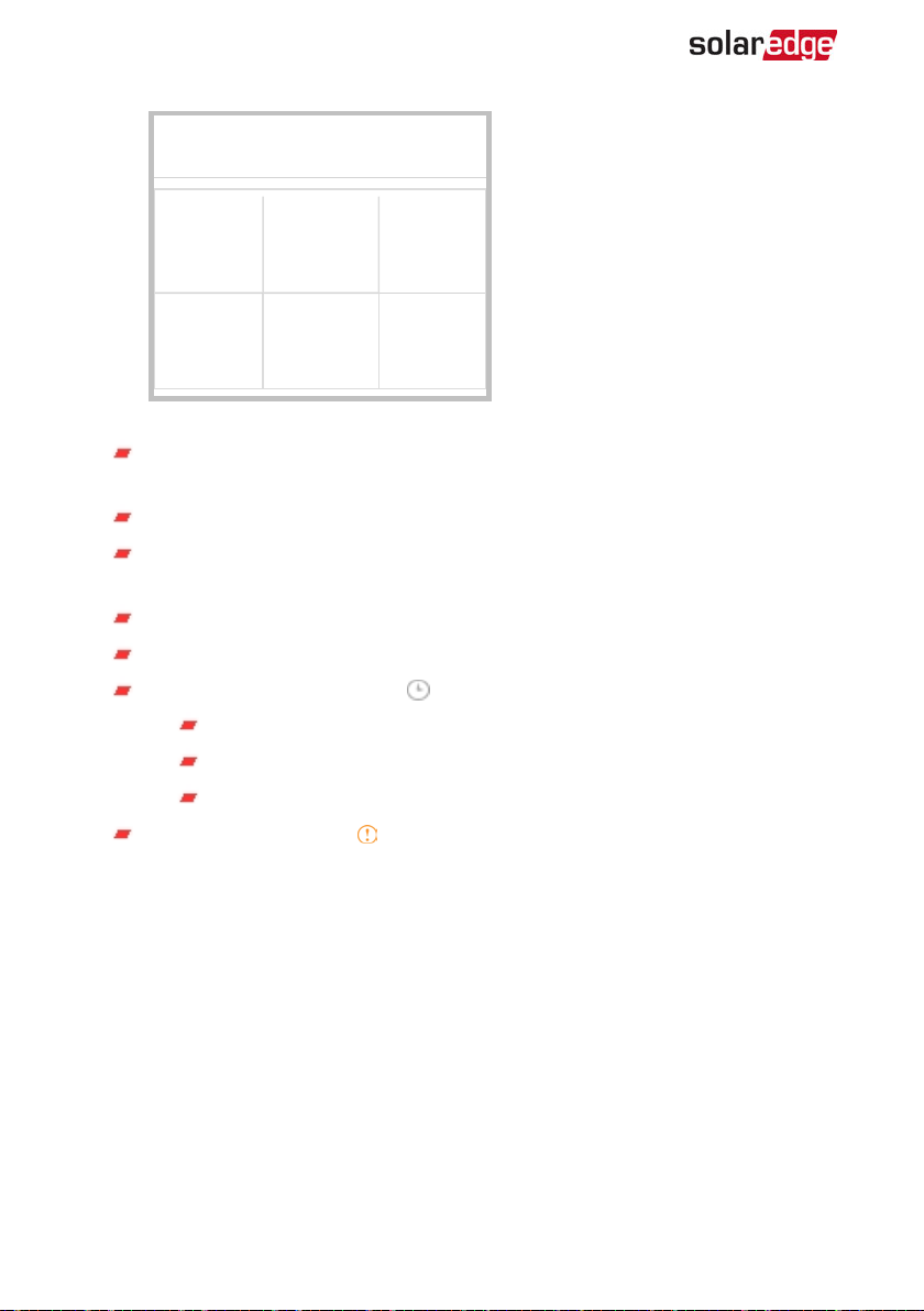
Communication Status
This screen displays the status of connection option(s): LAN, RS485, Wi-Fi, cellular or
ZigBee Plug-in.
Three Phase System Installation Guide MAN-01-00505-1.2
Page 45
44 Viewing System Status
Communication
LAN
Connected
Cellular
N/A
For each communication option, one of the following statuses is displayed:
Connected: The inverter established a successful connection and
communication with the specified server port
NC: Not Connected. Refer to
S_OK: The connection to the monitoring platform is successful (should appear
only if the inverter is connected to the server)
N/A : Not Applicable
x of y: Number of devices connected out of all devices
Temporarily displayed (with a clock sign):
Initializing communication
Connecting to a network
Connecting to SolarEdge servers
Error message (with the sign). Refer to
page 64.
RS485-1
SESlave
NC
Wi-Fi
NC
RS485-2
Modbus
2 of 2
ZigBee
MPSlave
M not Found
Troubleshooting Communication
Troubleshooting Communication
on page 64
on
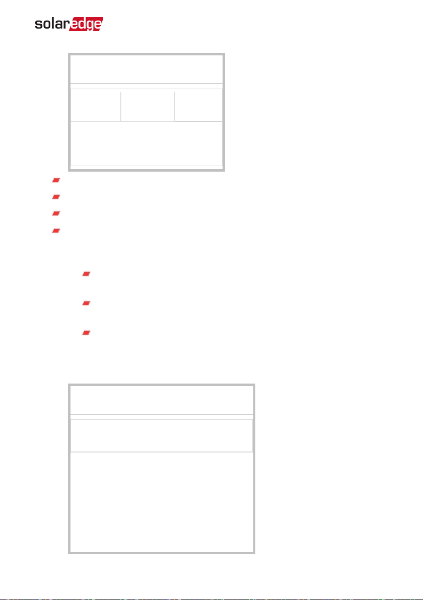
Inverter Energy Status
Displays the total energy produced during the last day, month, year and since inverter
installation.
-Three Phase System Installation Guide MAN-01-00505-1.2
Page 46
Chapter 5: Activating, Commissioning and Configuring the System Using the
Inverter SetApp 45
Inverter Energy
Today
45 kWh
Today: since midnight
This Month: since 1st of the current month
This Year: since January 1st
Total (Wh): The inverter total energy. If an external meter is installed, the value
displayed in this line depends on the meter type connected to the inverter and
its location:
If a bidirectional meter is connected at the consumption point, this
value is the consumed energy.
If the meter is installed at the production point, this value is the energy
produced by the site.
If the meter is installed at the grid connection point, this value is the
energy exported to the grid.
Meter Status
This Month
1.14 MWh
Total: 41.03 MWh
This Year
13.68 MWh
Meters
Export – RS485-2 Modbus ID #2
Status: OK
Three Phase System Installation Guide MAN-01-00505-1.2
Page 47
46 Reporting and Monitoring Installation Data
Type and function: Displays the meter functionality (Production, Export, Import,
Export+Import)
Status: Displays OK if the meter is communicating with the inverter
<Error message>: If there is a meter error, it is displayed in this line.
Power: Depending on the meter type connected to the inverter, this line
displays the exported or imported power
Energy: The total energy read by the meter. The value displayed in this line
depends on the meter type connected to the inverter and its location:
If a bidirectional meter is connected at the consumption point, this
value is the consumed energy.
If the meter is installed at the production connection point, this value is
the energy produced by the site.
If the meter is installed at the grid connection point, this value is the
energy exported to the grid.
NOTE
This data is accumulated according to an internal real-time
clock.
Reporting and Monitoring Installation Data
NOTE
Monitoring the site requires connecting the inverter to the monitoring
platform, using any of the wired or wireless options available from SolarEdge.
Refer to
The Monitoring Platform
The monitoring platform provides enhanced PV performance monitoring and yield
assurance through immediate fault detection and alerts at the module , string and
system level.
Using the platform, you can:
View the latest performance of specific components.
Find under-performing components, such as modules, by comparing their
performance to that of other components of the same type.
Pinpoint the location of alerted components using the physical layout.
Setting Up Communication
-Three Phase System Installation Guide MAN-01-00505-1.2
on page 49.
Page 48
Chapter 5: Activating, Commissioning and Configuring the System Using the
Inverter SetApp 47
The monitoring platform enables accessing site information, including up-to-date
information viewed in a physical or logical view:
Logical Layout: Shows a schematic tree-layout of the components in the
system, such as: inverters, strings, modules, meters and sensors, as well as their
electrical connectivity. This view enables you to see which modules are
connected in each string, which strings are connected to each inverter, and so
on.
Physical Layout: Provides a bird's eye view of the actual placement of modules
in the site, and allows pinpoint issues to the exact location of each module on a
virtual site map.
If you do not report the mapping of the installed power optimizers, the monitoring
platform will show the logical layout indicating which power optimizers are connected
to which inverter, but will not show strings or the physical location of power optimizers.
The monitoring platform includes a built-in help system, that guides you
through the monitoring functionality.
For more information, refer to https://www.solaredge.com/products/pv-
monitoring#/.
Creating Logical and Physical Layout using
Installation Information
To display a logical layout, insert the inverterserial number in the new site created in the
monitoring platform. When the communication between the inverter and the
monitoring server is established, the logical layout is displayed.
To display a physical layout, you need to map the locations of the installed power
optimizers. To map the locations, use one of the methods described in the next sections.
Designer
Designer recommends inverter and power optimizer selection per site
size and enables report generation.You can create a project in Designer
and export the site design with the string layout to the monitoring
platform.
For more information, refer to
https://www.solaredge.com/products/installer-tools/designer#/.
Three Phase System Installation Guide MAN-01-00505-1.2
Page 49
48 Reporting and Monitoring Installation Data
Mapper Application
Use the Mapper smart phone application to scan the power optimizer and inverter 2D
bar-codes and create a virtual map of a PV site for enhanced monitoring and easier
maintenance.
Th Mapper application is integrated with the monitoring platform and enables:
Simple on-site registration of new systems.
Creating, editing and verifying system physical layout.
Scanning and assigning the power optimizer serial number to the correct
module in the system physical layout.
For detailed information, refer to the
Creating new sites using the Mapper mobile application
Mapping existing sites using the Mapper mobile application
Mapper
demo movies:
Physical Layout Editor
1. If you are a registered installer, access the monitoring platform site
creation page at https://monitoring.solaredge.com/solaredge-
web/p/home#createSites. If you have not yet signed up, go to
https://monitoring.solaredge.com/solaredge-web/p/createSelfNewInstaller.
2. Fill out all required information in the screen, which includes
information about your installation, as well as details about its logical
and physical mapping.
Using a Paper Template
Fill out the Physical Layout Template (downloadable from the SolarEdge
website http://www.solaredge.com/files/pdfs/physical-layout-
template.pdf)using the detachable 2D barcode stickers on each power
optimizer. Once the form is completed, use the Mapper to scan the 2D
codes and create the map in the monitoring platform. Optionally, you can
send the sticker sheet to SolarEdge Support for physical layout creation.
-Three Phase System Installation Guide MAN-01-00505-1.2
Page 50
Chapter 6: Setting Up Communication 49
Chapter 6: Setting Up Communication
The inverter sends the following information to the monitoring platform:
Power optimizer information received via the DC power lines (the PV output
circuit).
Inverter information
Information of any other connected devices.
This chapter describes setting up communication between:
The inverter and the monitoring platform through the Internet (wired/ wireless),
or through a cellular connection.
Multiple inverters for a master/slave configuration.
Communication setup is not required for power harvesting, however it is needed for
using the monitoring platform.
CAUTION!
When connecting the communication cables, make sure that the ON/OFF/P
switch at the bottom of the inverter (and the switch of the DC Safety Unit if
applicable) is turned OFF, and the AC is turned OFF.
When configuring the communication parameters
removed
Safety Unit if applicable) is OFF, and the AC is turned ON.
, make sure that the ON/OFF/P switch (and the switch of the DC
while the inverter cover is
Communication Options
The following types of communication can be used to transfer the monitored
information from the inverter to the monitoring platform.
Only communication products offered by SolarEdge are supported.
Always connect the communication options when the relevant devices are powered
down - Commercial Gateway, inverter, etc.
Ethernet
Ethernet is used for a LAN connection. For connection instructions refer to
Ethernet (LAN) Connection
Three Phase System Installation Guide MAN-01-00505-1.2
on page 52 .
Creating an
Page 51
50 Communication Options
RS485
RS485 is used for the connection of multiple SolarEdge devices on the same bus in a
master-slave configuration. RS485 can also be used as an interface to external devices,
such as meters and third party data loggers.
RS485-1: Enables the connection of multiple devices (inverters/Commercial
Gateway)over the same bus, such that connecting only one device to the
Internet is sufficient to provide communication services for all the devices
on the bus.
RS485-2: Enables connection of multiple SolarEdge devices and of nonSolarEdge devices over the same bus.
Wi-Fi
This communication option enables using a Wi-Fi connection for connecting to the
monitoring platform.
The Wi-Fi station is built into the inverter. An antenna is required and available from
SolarEdge for connection to the monitoring platform.
Cellular (GSM, CDMA)
This wireless communication option (purchased separately) enables
using a cellular connection to connect one or several devices (depending
on the data plan used) to the monitoring platform.
The GSM/CDMA Plug-in is provided with a user manual, which should be
reviewed prior to connection. Refer to
https://www.solaredge.com/sites/default/files/cellular_gsm_installation_guide_
for_inverters_with_setapp.pdf
ZigBee
This option enables wireless connection to one or several Smart Energy products, which
automatically divert PV energy to home appliances.
The Smart Energy products are provided with an installation guide, which
should be reviewed prior to connection. Refer to
https://www.solaredge.com/products/device-control#/.
The ZigBee station is built into the inverter. An antenna is required and
available from SolarEdge.
-Three Phase System Installation Guide MAN-01-00505-1.2
Page 52
Chapter 6: Setting Up Communication 51
Communication Connectors
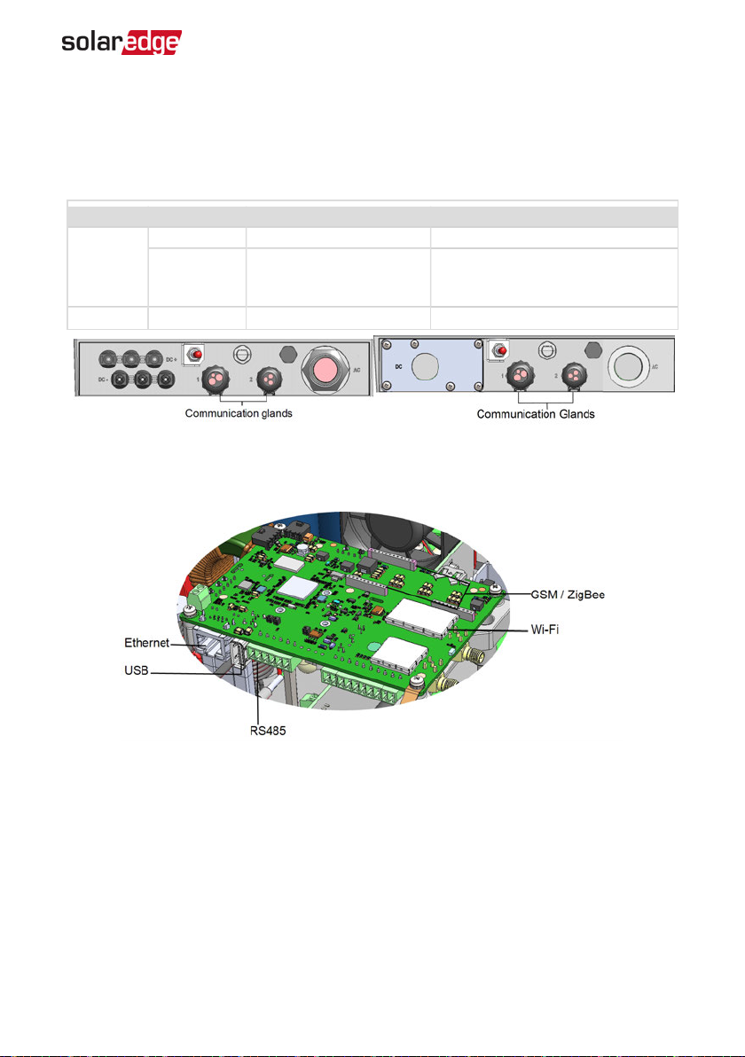
Two communication glands are used for connection of the various communication
options. Each gland has three openings. The table below describes the functionality of
each opening. Unused openings should remain sealed.
Gland# Opening Functionality Cable size (diameter)
One small External antenna cable 2-4 mm
1 (PG16)
2 (PG13.5) All three RS485, power reduction 2.5-5 mm
The communication board has a standard RJ45 terminal block for Ethernet connection,
and a 6-pin terminal block for RS485 connection, as shown below:
Two large
Ethernet connection
(CAT5/6), Cellular, ZigBee,
or Wi-Fi
Figure 17: Communication Glands
4.5-7 mm
Figure 18: Internal connectors
Three Phase System Installation Guide MAN-01-00505-1.2
Page 53
52 Removing the Inverter Cover
Removing the Inverter Cover
If the inverter cover is not already removed, use the following procedure for cover
removal.
To remove the inverter cover
1. Turn the inverter ON/OFF/P switch to OFF. Wait 5 minutes for the capacitors to
discharge.
2. Turn the Connection Unit (if applicable) to OFF.
3. Disconnect the AC to the inverter by turning OFF the circuit breakers on the
distribution panel.
4. Open the Allen screws of the inverter cover and carefully pull the cover horizontally
before lowering it.
CAUTION!
When removing the inverter cover, make sure not to damage the internal
components. SolarEdge will not be held responsible for any components
damaged as a result of incautious cover removal.
Creating an Ethernet (LAN) Connection
This communication option enables using an Ethernet connection to connect the
inverter to the monitoring platform through a LAN.
Ethernet cable specifications:
Cable type – a shielded Ethernet cable (Cat5/5E STP) may be used
Maximum distance between the inverter and the router – 100 m/ 330 ft.
NOTE
If using a cable longer than 10 m / 33 ft in areas where there is
a risk of induced voltage surges by lightning, it is recommend
to use external surge protection devices.
For details refer to: http://www.solaredge.com/files/pdfs/lightning_
surge_protection.pdf.
-Three Phase System Installation Guide MAN-01-00505-1.2
Page 54
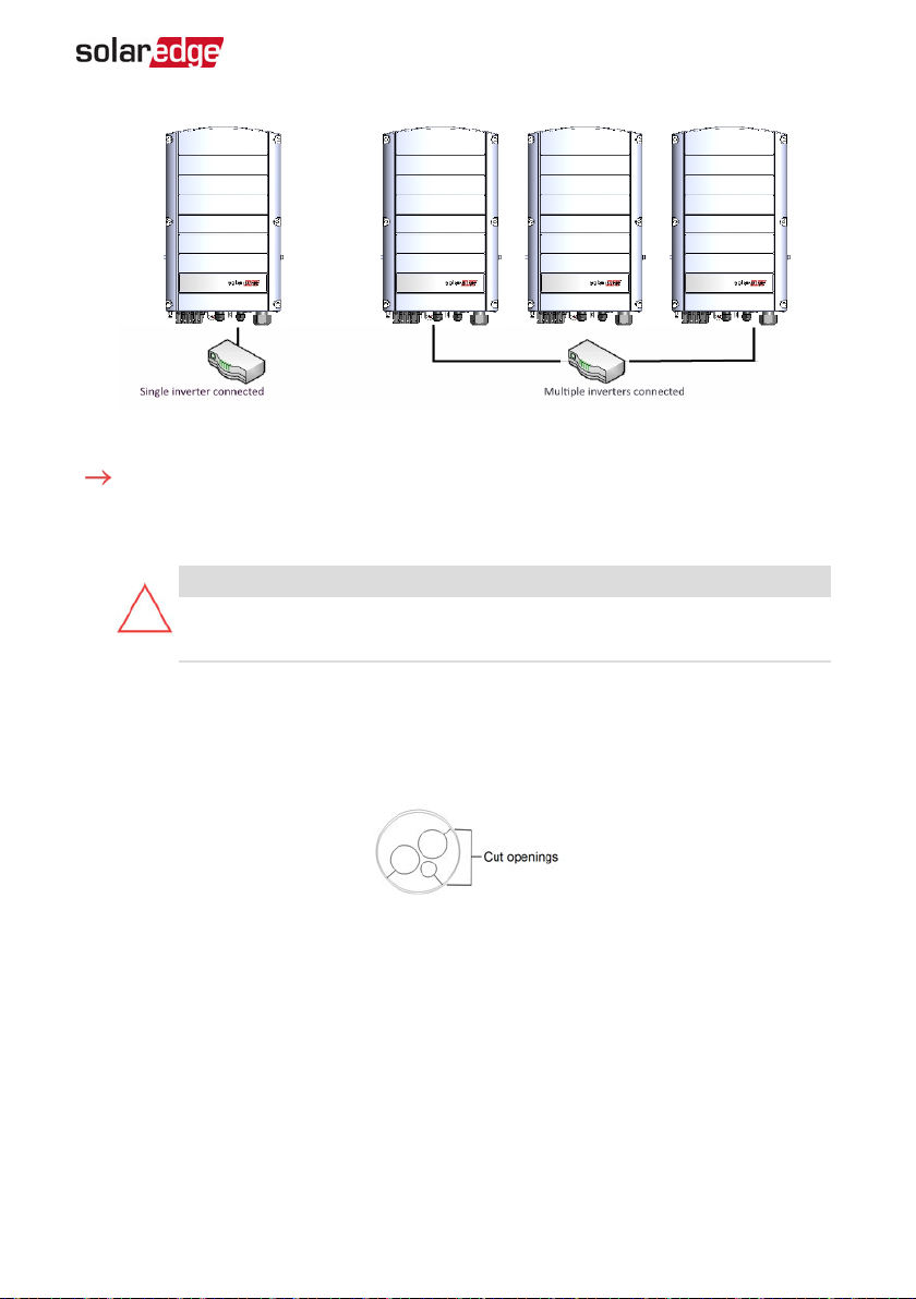
Figure 19: Example of Ethernet connection
To connect the Ethernet cable:
1. Remove the inverter cover .
Open the communication gland #1.
2.
CAUTION!
The gland includes a rubber waterproof fitting, which should be used to
ensure proper sealing.
Chapter 6: Setting Up Communication 53
3. Remove the plastic seal from one of the large opening .
4. Remove the rubber fitting from the gland and insert the CAT5/6 cable through the
gland and through the gland opening in the inverter .
Push the cable into the cut opening of the rubber fitting.
5.
Figure 20: Rubber fitting
CAT5/6 standard cables have eight wires (four twisted pairs), as shown in the diagram
below. Wire colors may differ from one cable to another. You can use either wiring
standard, as long as both sides of the cable have the same pin-out and color-coding.
Three Phase System Installation Guide MAN-01-00505-1.2
Page 55
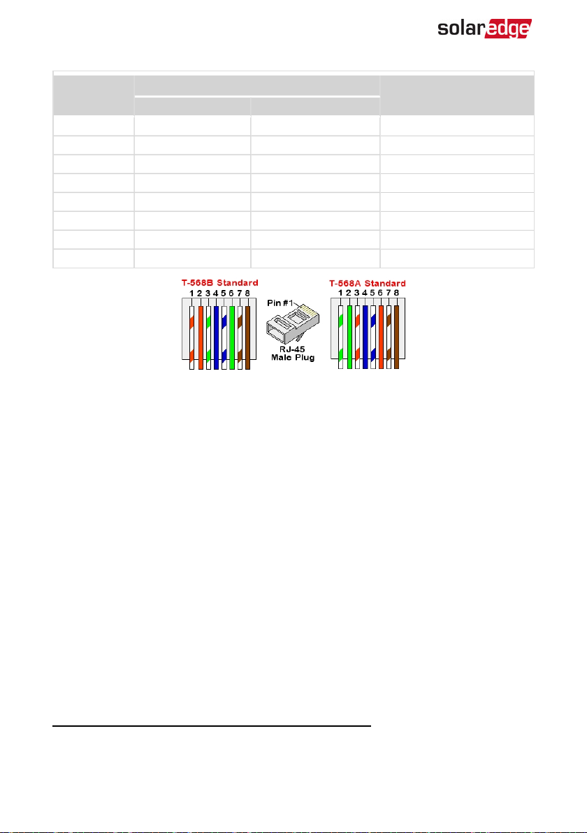
54 Creating an Ethernet (LAN) Connection
(1)
10Base-T Signal
100Base-TX Signal
RJ45 Pin #
Wire Color
T568B T568A
1 White/Orange White/Green Transmit+
2 Orange Green Transmit3 White/Green White/Orange Receive+
4 Blue Blue Reserved
5 White/Blue White/Blue Reserved
6 Green Orange Received7 White/Brown White/Brown Reserved
8 Brown Brown Reserved
Figure 21: Standard cable wiring
6. Use a pre-crimped cable to connect via gland #1 to the RJ45 plug on the inverter's
communication board or, if using a spool of cable, connect as follows:
a. Insert the cable through gland #1.
b. Remove the cable’s external insulation using a crimping tool or cable cutter and
expose eight wires.
c. Insert the eight wires into an RJ45 connector, as described in
Figure 21
.
d. Use a crimping tool to crimp the connector.
e. Connect the Ethernet connector to the RJ45 port on the communication board.
(1)
The inverter connection does not support RX/TX polarity change. Supporting crossover Ethernet cables depends on
the switch capabilities.
-Three Phase System Installation Guide MAN-01-00505-1.2
Page 56
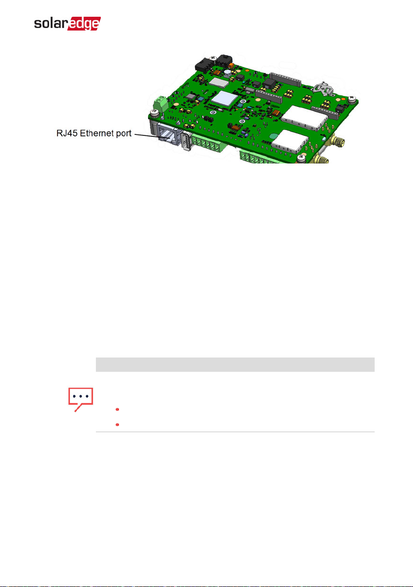
Chapter 6: Setting Up Communication 55
Figure 22: The RJ45 Ethernet connection
7. For the switch/router side, use a pre-crimped cable or use a crimper to prepare an
RJ45 communication connector: Insert the eight wires into the RJ45 connector in the
same order as above (
Figure 21
).
8. Connect the cable RJ45 connector to the RJ45 port of the Ethernet switch or router.
You can connect more than one inverter to the same switch/router or to different
switches/routers, as needed. Each inverter sends its monitored data independently
to the monitoring platform.
The inverter is configured by default to LAN. If reconfiguration is required:
9.
a. Make sure the ON/OFF/P switch is OFF.
b. Turn ON the AC to the inverter by turning ON the circuit breaker on the main
distribution panel.
Configure the connection as described in
c.
Communication
on page 37.
NOTE
If your network has a firewall, you may need to configure it to enable
the connection to the following address:
Destination Address: prod2.solaredge.com
TCP Port: 22222, 22221, or 80 (for incoming and outgoing data)
10. Verify the connection, as described in
Three Phase System Installation Guide MAN-01-00505-1.2
Verifying the Connection
on page 60.
Page 57
56 Creating an RS485 Bus Connection
Creating an RS485 Bus Connection
The RS485 option enables creating a bus of connected inverters, consisting of up to 31
slave inverters and 1 master inverter. Using this option, inverters are connected to each
other in a bus (chain), via their RS485 connectors. The first and last inverters in the
chain must be terminated as described on page 58.
RS485 wiring specifications:
Cable type: Min. 3-wire shielded twisted pair (a shielded Ethernet cable (Cat5/5E
STP) may be used)
Wire cross-section area: 0.2- 1 mm²/ 24-18 AWG (a CAT5 cable may be used)
Maximum nodes: 32
Maximum distance between first and last devices: 1 km /3300 ft.
NOTE
If using a cable longer than 10 m/33 ft in areas where there is a
risk of induced voltage surges by lightning, it is recommend to
use external surge protection devices. For details refer to:
https://www.solaredge.com/sites/default/files/lightning_surge_
protection.pdf.
If grounded metal conduit are used for routing the communication wires, a
lightning protection device is not required.
If not using surge protection, connect the grounding wire to the first inverter
in the RS485 chain; ensure it is not in contact with other wires. For inverters
with a DC Safety Unit, connect the grounding wire to the grounding bus-bar
in the DC Safety Unit.
The following sections describe how to physically connect the RS485 bus and how to
configure the bus.
To connect the RS485 communication bus:
1. Remove the inverter cover as described in
2. Remove the seal from one of the openings in communication gland #2 and insert
the wire through the opening.
Pull out the 6-pin RS485 terminal block connector, as shown below:
3.
-Three Phase System Installation Guide MAN-01-00505-1.2
Removing the Inverter Cover
on page 52.
Page 58
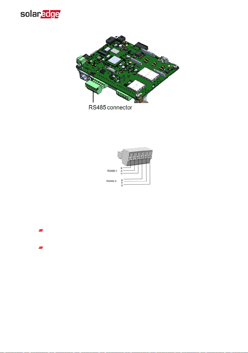
Chapter 6: Setting Up Communication 57
Figure 23: The RS485 terminal block
Loosen the screws of pins A(+), B(-), and G on the left of the RS485 terminal block
4.
(RS485-1 or RS485-2).
Figure 24: RS485 terminal block
Insert the wire ends into the G, A and B pins shown above. Use Four- or six-wire
5.
twisted pair cable for this connection.
You can use any color wire for each of the A, B and G connections, as long as:
The same color wire is used for all A pins the same color for all B pins and
the same color for all G pins
The wire for G is not from the same twisted pair as A or B.
For creating an RS485 bus - connect all B, A and G pins in all inverters. The following
6.
figure shows this connection schema:
Three Phase System Installation Guide MAN-01-00505-1.2
Page 59
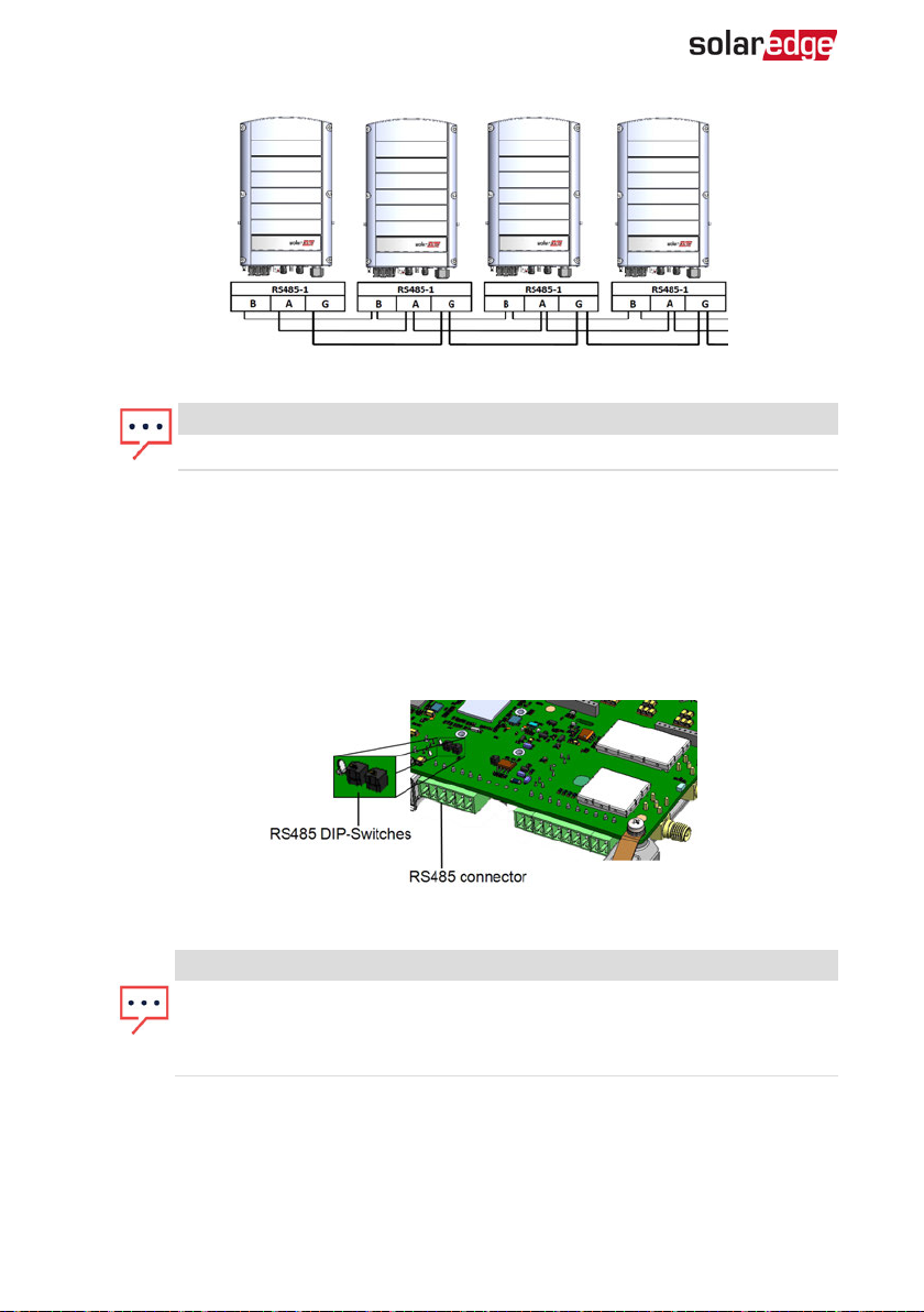
58 Creating an RS485 Bus Connection
Figure 25: Connecting the inverters in a chain
NOTE
Do not cross-connect B, A and G wires.
7. Tighten the terminal block screws.
8. Check that the wires are fully inserted and cannot be pulled out easily.
Push the RS485 terminal block firmly all the way into the connector on the right side
9.
of the communication board.
Terminate the first and last SolarEdge device in the chain by switching a termination
10.
DIP-switch inside the inverter to ON (move the left switch up). The switch is located
on the communication board and is marked SW7SW1.
Figure 26: RS485 termination switch
NOTE
Only the first and last SolarEdge devices in the chain should be terminated.
The other inverters in the chain should have the termination switch OFF
(down position).
11. If not using surge protection, connect the grounding wire to the first inverter in the
RS485 chain; make sure the grounding wire is not in contact with other wires. For
inverters with a DC Safety Unit, connect the grounding wire to the grounding busbar in the DC Safety Unit.
-Three Phase System Installation Guide MAN-01-00505-1.2
Page 60
Chapter 6: Setting Up Communication 59
To connect to the monitoring platform:
1. Designate a single inverter as the connection point between the RS485 bus and the
monitoring platform. This inverter will serve as the master inverter.
To configure the RS485 bus:
All inverters are configured by default as slaves. To configure the master:
1. Verify the ON/OFF/P switch is OFF.
2. Verify that AC is on.
3. Use SetApp to access the Commissioning menu screen as described in
Communication
From the Commissioning menu tap Communication. The Communication screen is
4.
on page 37.
displayed.
Select the following to configure the connection:
5.
Server è LAN
RS485-1 è Protocol è SolarEdge Master
RS485-1 è Slave Detect
The system starts automatic detection of the slave inverters connected to the master
inverter. The inverter should report the correct number of slaves. If it does not, verify
the connections and terminations.
6. To check the slave IDs and last communication time, select RS485-1 è Slave List.
7. Verify the connection of the master to the monitoring platform, as described in the
next section.
Three Phase System Installation Guide MAN-01-00505-1.2
Page 61
60 Verifying the Connection
Verifying the Connection
After connecting and configuring a communication option, perform the following
steps to check that the connection to the monitoring server has been successfully
established.
Access the Status screen:
1.
a. If not already ON - turn ON AC to the inverter by turning ON the circuit breaker
on the main distribution panel.
Open SetApp and follow the instructions on the screen (scan the inverter bar-
b.
code; move the ON/OFF/P switch to P position (for less than 5 sec) and release).
The mobile device creates a Wi-Fi connection with the inverter and displays the
main Commissioning screen.
Status
Inverter
SN 07318000C
Power Voltage Frequency
Optimizers
Connected
Status
Production
CosPhi
1.00
Voltage Temp Fan
Commissioning
Limit
No Limit
S_OK
Server Connected
Switch
ON
Country
Netherlands
Check that S_OK- Server Connected status appears in the main inverter section.
2.
3. Scroll down to the Communication section and check that the communication
options are as required. For more information refer to
page 43.
-Three Phase System Installation Guide MAN-01-00505-1.2
Communication Status
on
Page 62
Communication
Chapter 6: Setting Up Communication 61
LAN
Connected
Cellular
N/A
RS485-1
SESlave
NC
Wi-Fi
NC
RS485-2
Modbus
2 of 2
ZigBee
MPSlave
M not Found
Three Phase System Installation Guide MAN-01-00505-1.2
Page 63
62 Appendix A: Errors and Troubleshooting
Appendix A: Errors and Troubleshooting
This appendix describes general system problems, and how to troubleshoot them. For
further assistance, contact SolarEdge Support.
Identifying Errors
Errors may be indicated in various system interfaces: On the inverter bottom panel, a
red LEDindicates an error. In the monitoring platform and the SetApp, errors are
displayed with codes.
For more information on the codes displayed for error and warning
messages, refer to http://www.solaredge.com/sites/default/files/se-inverter-
installation-guide-error-codes.pdf. This document describes errors that
appear in SetApp, monitoring platform, and LCD (for inverters with LCD).
To identify the error types, use the methods described below.
To identify the error type using the inverter LEDs:
1. Move the ON/OFF/P switch to P position for less than 5 seconds and release it.
Observe the LED lights and use the following table to identity the
2.
error type. For more information, refer to
https://www.solaredge.com/leds.
Error type
Arc detected ON OFF OFF
Isolation or RCD problem Blinking OFF OFF
Grid error OFF ON OFF
High temperature OFF Blinking OFF
Pairing failed OFF OFF ON
Other issue OFF OFF Blinking
To identify the error type using the monitoring platform:
1. Open the site dashboard and click the Layout icon.
Right-click the inverter and select Info from the menu (
2.
details window is displayed (
Figure 28
).
-Three Phase System Installation Guide MAN-01-00505-1.2
LEDcolor and state
Red Green Blue
Figure 27
). The inverter
Page 64
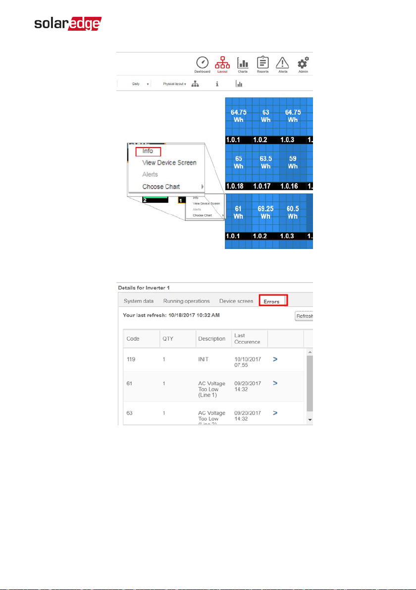
Click the Errors tab. The list is displayed.
3.
Appendix A: Errors and Troubleshooting 63
Figure 27: Inverter menu
Figure 28: Inverter details - Error list
Three Phase System Installation Guide MAN-01-00505-1.2
Page 65
64 Troubleshooting Communication
Troubleshooting Communication
Troubleshooting Ethernet (LAN)Communication
The possible errors and their troubleshooting are detailed in the following table:
Error Message Cause and Troubleshooting
LAN cable disconnected
No DHCP
Configure Static IPor set to DHCP
Gateway not responding
No Internet connection
No connection to SolarEdge servers
Physical connection fault. Check the cable pinout assignment and cable connection
IP settings issue. Check the router and inverter
configuration. Consult your network IT.
Ping to router failed. Check the physical connection to the
switch/ router. Check that the link LED at the router /switch
is lit (indicating phy-link). If OK - contact your network IT,
otherwise replace the cable or change it from cross to
straight connection.
Ping to google.com failed. Connect a laptop and check
for internet connection. If internet access is unavailable,
contact your IT admin or your internet provider.
For Wi-Fi networks, ensure that user-name and password
are as defined in the internet provider AP/ router.
Ping or connection to SolarEdge server failed. Check the
SolarEdge server address, under LAN Conf sub-menu:
Address: prod.solaredge.com
Port: 22222
Check with your network administrator whether a firewall
or another device is blocking transmission.
Troubleshooting RS485 Communication
If the message RS485 Master Not Found appears in the Status screen, check the
connections to the master device and fix if required.
If after slave detection the number of slaves displayed for the master under
RS485-X ConfèSlave Detect is lower than the actual number of slaves, refer
to the following application note to identify missing slaves and troubleshoot
connectivity problems:
https://www.solaredge.com/sites/default/files/troubleshooting_undetected_RS485_
devices.pdf
-Three Phase System Installation Guide MAN-01-00505-1.2
Page 66
Appendix A: Errors and Troubleshooting 65
Additional Troubleshooting
1. Check that the modem or hub/router is functioning properly.
2. Check that the connection to the internal connector on the communication board is
properly done.
3. Check that the selected communication option is properly configured.
4. Use a method independent of the SolarEdge device to check whether the network
and modem are operating properly. For example, connect a laptop to the Ethernet
router and connect to the Internet.
5. Check whether a firewall or another type of network filter is blocking
communication.
Power Optimizer Troubleshooting
Problem Possible cause and troubleshooting
Power optimizers are shaded.
If you connected the inverter to the monitoring
Pairing failed
String voltage is 0V
String voltage not 0V but lower than
number of optimizers
platform, retry pairing remotely (during
sunlight). Make sure to leave the inverter
ON/OFF switch ON and that S_OK appears in
the status screen.
Power optimizer (s) output is disconnected.
Connect all power optimizer outputs.
Power optimizer(s) not connected in the string.
Connect all power optimizers
Module(s) not connected properly to power
optimizer inputs (not applicable to smart
modules).
Connect the modules to the optimizer inputs
String reverse polarity.
Check string polarity using a voltmeter and
correct if needed.
Three Phase System Installation Guide MAN-01-00505-1.2
Page 67
66 Power Optimizer Troubleshooting
Problem Possible cause and troubleshooting
String voltage is higher than number
of optimizers
WARNING!
If the measured voltage is
too high, the installation
may not have a safe low
voltage. PROCEED WITH
CARE! A deviation of ±1%
per string is reasonable.
Extra power optimizer(s) connected in the string
(not applicable to smart modules).
Check if an extra power optimizer is connected
in the string. If not – proceed to next solution.
A module is connected directly to the string,
without a power optimizer (not applicable to
smart modules).
Verify that only power optimizers are connected
in the string and that no module outputs are
connected without a power optimizer. If the
problem persists, proceed to the next step.
Power optimizer(s) malfunction.
1. Disconnect the wires connecting the power
optimizers in the string.
2. Measure the output voltage of each power
optimizer to locate the power optimizer that
does not output 1V safety voltage. If a
malfunctioning power optimizeris located,
check its connections, polarity, module, and
voltage.
3. Contact SolarEdge Support. Do not continue
before finding the problem and replacing the
malfunctioning power optimizer. If a
malfunction cannot be bypassed or resolved,
skip the malfunctioning power optimizer,
thus connecting a shorter string.
-Three Phase System Installation Guide MAN-01-00505-1.2
Page 68
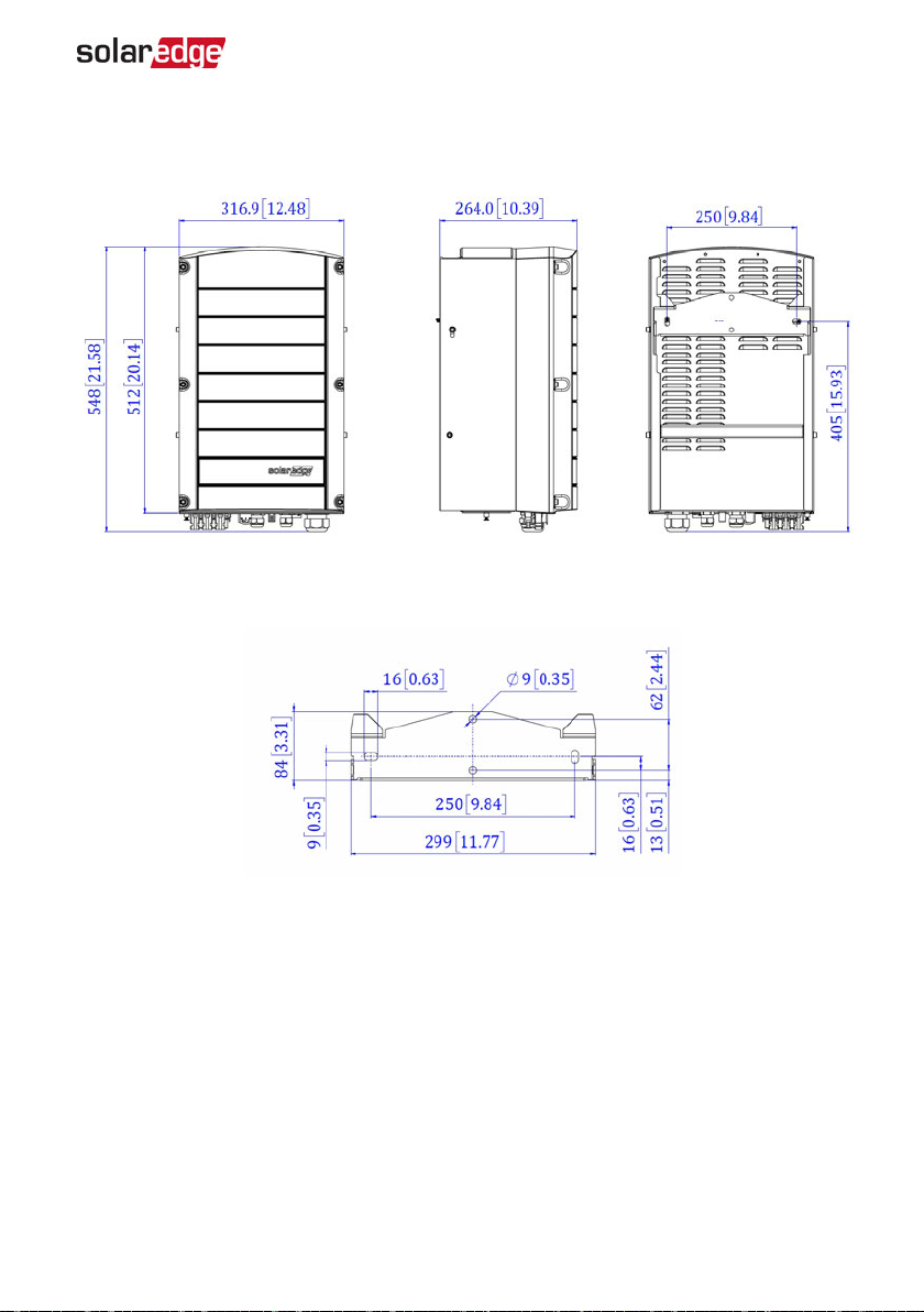
Appendix B: Mechanical Specifications 67
Appendix B: Mechanical Specifications
Figure 29: Inverter with bracket - front, side and rear views
Figure 30: Inverter mounting bracket
Three Phase System Installation Guide MAN-01-00505-1.2
Page 69
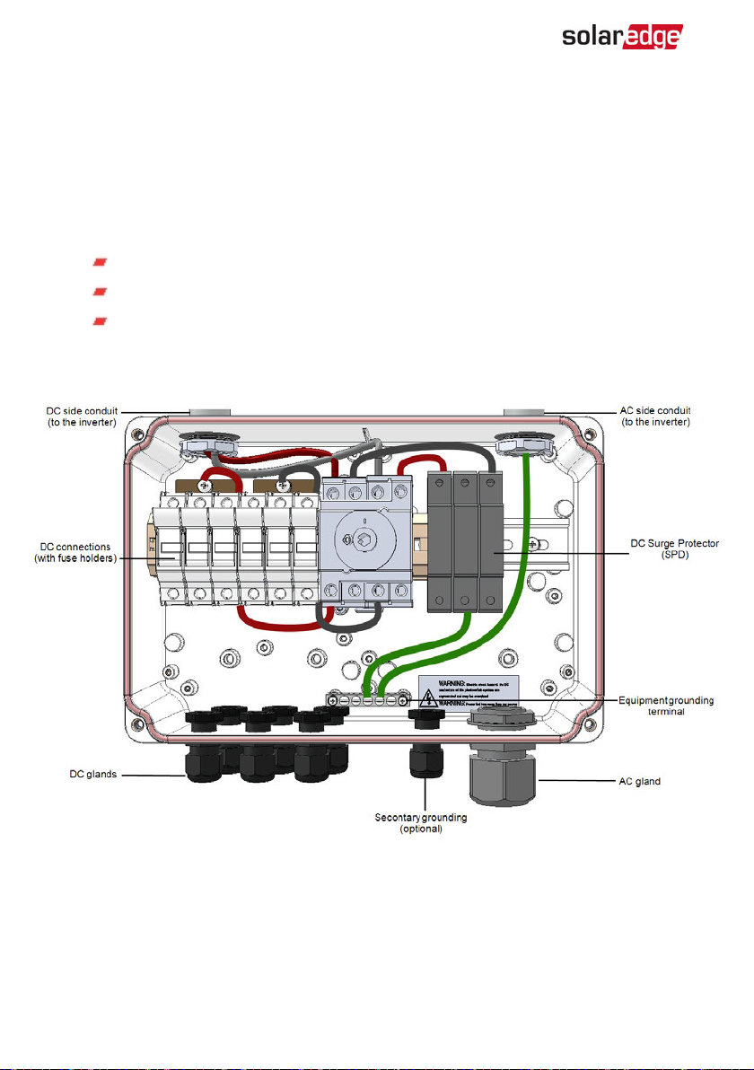
68 Appendix C: Connecting the AC and DCStrings to the DC Safety Unit
Appendix C: Connecting the AC and DCStrings
to the DC Safety Unit
Some inverter models are supplied with an integrated DC Safety Unit. This appendix
describes how to connect the AC grid and DC strings to the DC Safety Unit.
The DC Safety Unit includes:
Mechanical DCswitch (2-pole disconnection)
DCsurge protection (SPD, Type II)
DCfuses (plus & minus; optional)
This appendix describes connections to DC Safety Unit with or without fuses. The
following figure illustrates the DC Safety Unit supplied with fuses.
Figure 31: Inside the DC Safety Unit with fuses
-Three Phase System Installation Guide MAN-01-00505-1.2
Page 70
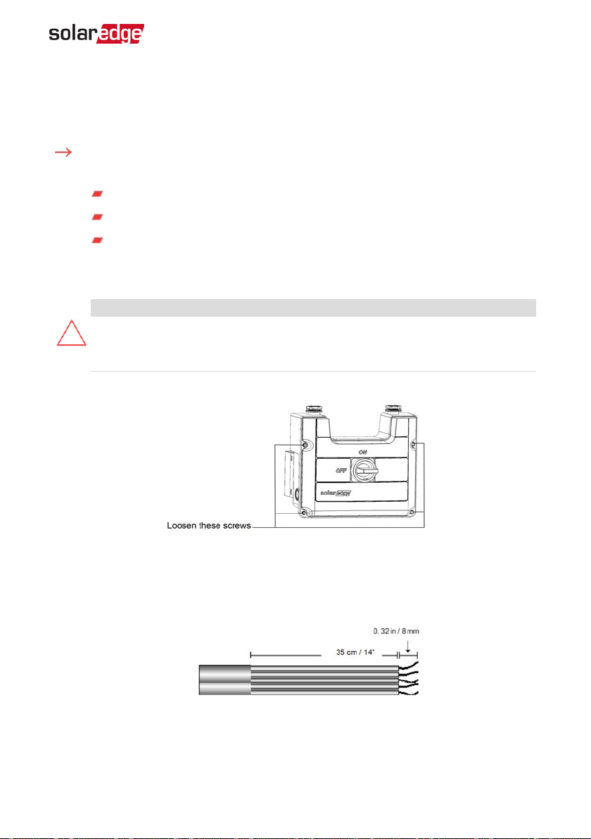
Appendix C: Connecting the AC and DCStrings to the DC Safety Unit 69
Connecting the ACGrid to the Inverter
Use a five-wire cable for this connection. The maximum wire size for the input terminal
blocks is 16 mm².
To connect the AC grid to the inverter via the DC Safety Unit:
1. Turn OFF the following:
The inverter ON/OFFswitch
The AC circuit breaker
The DC Safety Unit
2. Open the inverter cover: Release the Allen screws and carefully move the cover
horizontally before lowering it.
CAUTION!
When removing the cover, make sure not to damage internal components.
SolarEdge will not be held responsible for any components damaged as a result
of incautious cover removal.
3. Loosen the screws on the front cover of the DC Safety Unit, as shown below:
Figure 32: Opening the DC Safety Unit cover
4. Remove the DC Safety Unit cover.
5. Strip 35 cm of the external cable insulation and strip 8 mm of the internal wire
insulation.
Figure 33: Insulation stripping – AC
6. Open the AC cable gland and insert the cable through the gland (see
Three Phase System Installation Guide MAN-01-00505-1.2
Figure 31
).
Page 71
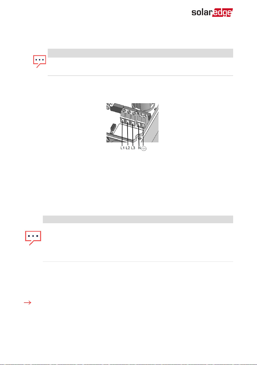
70 Connecting the Strings to the DC Safety Unit
Connect the grounding wire to the equipment grounding terminal in the DC Safety
7.
Unit.
NOTE
Connect the equipment grounding before connecting the AC wires to the
AC terminal block.
Insert the remaining four wires through the AC conduit to the inverter, and connect
8.
them to the appropriate terminal blocks in the inverter according to the labels on
the terminal blocks (N, L1, L2 and L3).
Figure 34: AC Terminals
9. Tighten the screws of each terminal with a torque of 1.2-1.5 N*m / 0.88-1.1 lb*ft.
10. Check that the wires are fully inserted and cannot be pulled out easily.
11. Tighten the AC cable gland with a torque of 5.0 N*m / 44 lb*in.
12. Verify that there are no unconnected wires.
13. Make sure the SPDs are tightly attached to the DIN rail.
NOTE
If power control is enabled, it is important to respect the order of grid lines
connection to the inverter. A 120deg phase difference should be kept between
L1 to L2 and between L2 to L3 (L1-L2-L3 and not, for example L1-L3-L2).
If the grid lines are not in this order, an error is displayed on the SetApp scrren
and the inverter will not produce power.
Connecting the Strings to the DC Safety Unit
Up to three strings may be connected in parallel to the DC input pairs of the switch. The
terminals are suitable for connection of copper conductors only.
To connect the strings to the DC Safety Unit:
1. Strip 8 mm of the DC wire insulation.
2. Insert the wires into the DC input glands of the DC Safety Unit .
Connect the DC wires according to the DC+ and DC- labels:
3.
-Three Phase System Installation Guide MAN-01-00505-1.2
Page 72
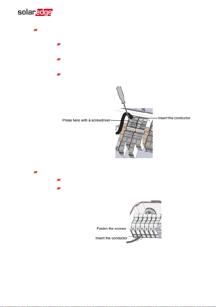
Appendix C: Connecting the AC and DCStrings to the DC Safety Unit 71
For DC terminals
without fuses
: Use a standard flat-blade screwdriver to
connect the wires to the spring-clamp terminals.
The screwdriver blade should fit freely in the terminal opening.
Too large a blade can crack the plastic housing.
Insert the screwdriver and press the release mechanism and open
the clamp.
Insert the conductor into the round opening and remove the
screwdriver – the wire is automatically clamped.
Figure 35: Spring-clamp terminals
For DC terminals
with fuses
:
Insert the wires into the side openings.
Fasten the screws at the top of the fuses. Apply torque of 3.4
N*M / 30 lb*in.
Figure 36: DC connection with fuses
4. Verify that there are no unconnected wires.
5. Close the DC Safety Unit cover: Attach the cover and secure it by tightening the four
screws with a torque of 1.2 N*m / 0.9 ft.*lb.
Three Phase System Installation Guide MAN-01-00505-1.2
Page 73

72 Connecting the Strings to the DC Safety Unit
6. Ensure proper cable entry sealing: inspect the entire cable run and use standard
sealants to avoid water penetration.
-Three Phase System Installation Guide MAN-01-00505-1.2
Page 74
Appendix D: SafeDC™ 73
Appendix D: SafeDC™
When AC supply to the inverter is shut off (by shutting off the AC breaker at the site), or
when the inverter ON/OFF/P switch is turned to OFF, the DC voltage drops to a safe
voltage of 1V per optimizer.
The SolarEdge inverters are certified for compliance with the following standards as
disconnection devices for PV generators, meaning that they can replace a DC
disconnect:
IEC 60947-3:1999 + Corrigendum: 1999 + A1:2001 + Corrigendum 1:2001 +
A2:2005;
DIN EN 60947-3
VDE 0660-107:2006-03
IEC 60364-7-712:2002-05
DIN VDE 0100-712:2006-06.
In compliance with these standards, the disconnection mechanism operates as follows:
Turn the inverter ON/OFF/P switch, located at the bottom of the inverter, to OFF, or
1.
disconnect the AC by shutting off the AC breaker at the site. The DC voltage
displayed on the SetApp screen begins to decrease.
2. When the DC voltage reaches a safe voltage, the PV connectors at the input to the
inverter can be disconnected. A galvanic separation then exists between the PV
array and the inverter.
WARNING!
SafeDC complies with IEC60947-3 when installing the system with a worst case
SafeDC voltage (under fault conditions) < 120V.
The worst case voltage is defined as: Voc,max+ (String Length-1)*1V, where:
Voc,max = Maximum Voc (at lowest temperature) of the PV module in
the string (for a string with multiple module models, use the max value)
String Length = number of power optimizers in the string
Three Phase System Installation Guide MAN-01-00505-1.2
Page 75
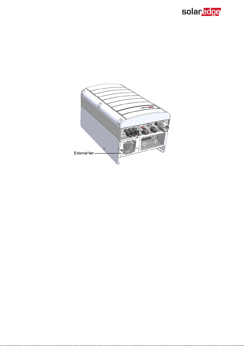
74 Appendix E: External Fan Maintenance and Replacement
Appendix E: External Fan Maintenance and Replacement
The inverter has two fans: one is internal and the other is accessible from the outside of
the inverter.
A fan replacement kit is available from SolarEdge.
Figure 37: Inverter external fan
Fan Maintenance
At least once a year, open the fan screen and clean the accumulated dust using a brush.
If the SetApp Status screen displays the status Not Working for the fan (refer to
Inverter Status
on page 41), replace the fan as described in the next section.
Main
External Fan Replacement
1. Turn OFF the inverter ON/OFF/P switch, and wait until the green LED is blinking ,
indicating that the DC voltage is safe (<50V), or wait five minutes before continuing
to the next step.
2. Turn OFF the DC Safety Unit(if applicable).
3. Disconnect the AC to the inverter by turning OFF the circuit breakers on the
distribution panel.
Use a standard screwdriver to unfasten the single screw of the fan cover and open
4.
the fan door.
-Three Phase System Installation Guide MAN-01-00505-1.2
Page 76
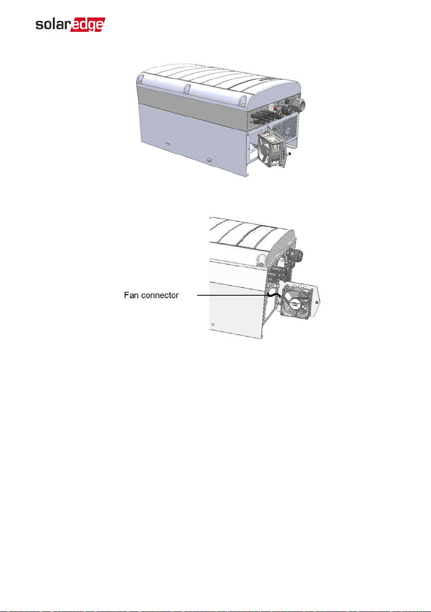
Appendix E: External Fan Maintenance and Replacement 75
Figure 38: Fan door open
Disconnect the fan connector and remove the fan.
5.
Figure 39: Fan connector
6. Connect the fan connector to the new fan.
7. Close the fan door and fasten the cover screws.
Three Phase System Installation Guide MAN-01-00505-1.2
Page 77
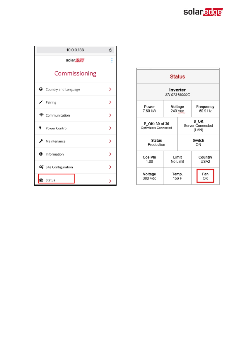
76 External Fan Replacement
After powering up the inverter, check the fan status on SetApp: Select
1.
Commissioning è Status.
ð
-Three Phase System Installation Guide MAN-01-00505-1.2
Page 78
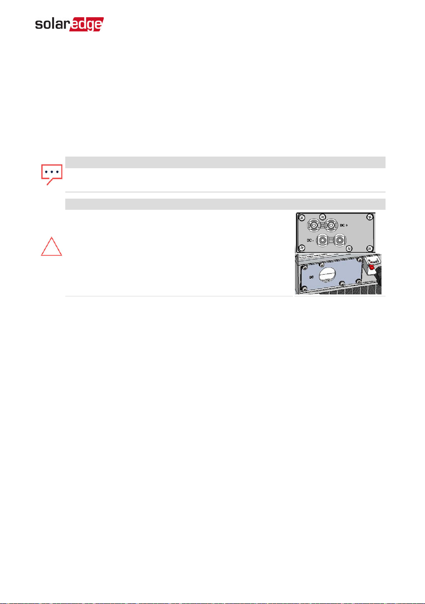
Appendix F: Replacing and Adding System Components 77
Appendix F: Replacing and Adding System Components
This appendix includes replacement procedures for the SolarEdge system components.
For inverter or DC Safety Unit replacement, typically only the part to be replaced is
supplied (not both inverter and DC Safety Unit). In this case, the DC Safety Unit should
be disconnected from the inverter as described herein.
NOTE
If you are permanently disassembling the installation or part of it, make sure to
use the disposal methods dictated by local regulations.
CAUTION!
Do not remove the six screws on the DC metal panel as it
may harm the inverter sealing and void the warranty.
Replacing an Inverter
1. Turn OFF the DC Safety Unit (if applicable).
2. Turn OFF the inverter ON/OFF/P switch, and wait until the green LED is blinking ,
indicating that the DC voltage is safe (<50V), or wait five minutes before continuing
to the next step.
3. Disconnect the AC to the inverter by turning OFF the circuit breakers on the
distribution panel.
4. Open the inverter cover as described in
5. Disconnect the DC plugs and AC wires from the inverter.
For inverters with a DC Safety Unit, unscrew the two conduit nuts in the inverter
6.
securing the DC Safety Unit to the inverter.
Removing the Inverter Cover
on page 52.
Three Phase System Installation Guide MAN-01-00505-1.2
Page 79
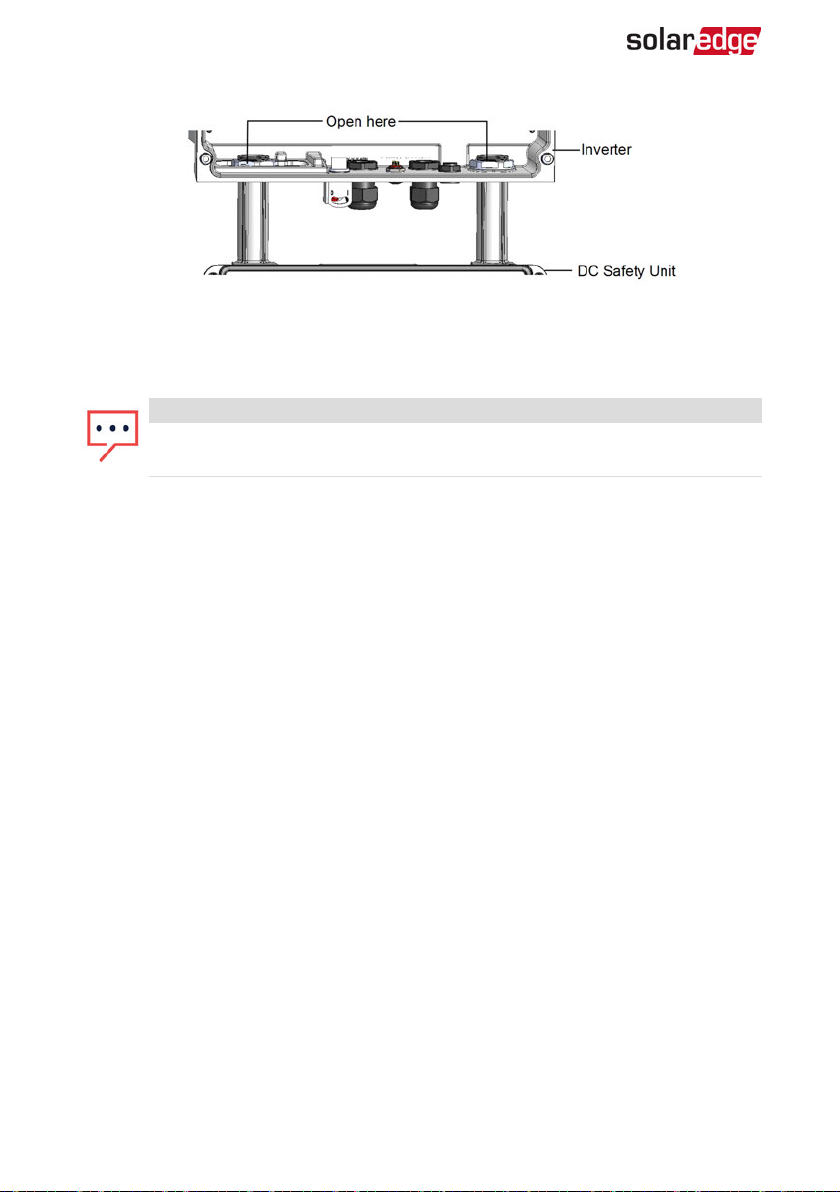
78 Replacing the DC Safety Unit
Figure 40: Conduit nuts
7. Remove the screws securing the inverter to the mounting bracket and remove the
inverter from the mounting bracket.
NOTE
If you remove the old inverter and do not immediately install a new one, use
insulation tape to isolate each of the AC and DC wires
8. Place the new inverter on the mounting bracket; insert the screws securing the
inverter to the mounting bracket.
9. For inverters with a Connection Unit, screwthe two conduit nuts in the inverter
securing the DC Safety Unit to the inverter.
10. Connect all the wires to the inverter: Follow the instructions of
on page 20 and
Inverter SetApp
11. Close the DC Safety Unit cover (if applicable) and the inverter cover.
Activating, Commissioning and Configuring the System Using the
on page 35.
Installing the Inverter
Replacing the DC Safety Unit
Removing the DC Safety Unit
1. Turn OFF the inverter ON/OFF/P switch, and wait until the green LED is blinking ,
indicating that the DC voltage is safe (<50V), or wait five minutes before continuing
to the next step.
2. Turn OFF the DC Safety Unit and the AC breaker of the distribution panel.
3. Open the inverter cover.
4. Disconnect the DC and AC wires from the inverter. If there are ferrite beads on the
DC and AC wires in the inverter, open them and set aside.
5. Disconnect the RS485 connector from the inverter communication board.
-Three Phase System Installation Guide MAN-01-00505-1.2
Page 80
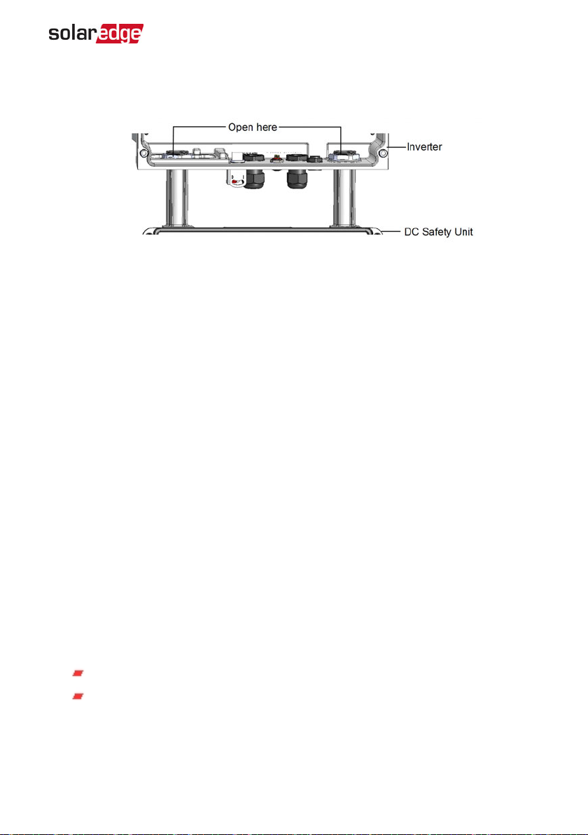
Appendix F: Replacing and Adding System Components 79
Unscrew the two conduit nuts in the inverter securing the DC Safety Unit to the
6.
inverter, as shown below:
Figure 41: Disconnecting the conduits
7. Open the DC Safety Unit cover and disconnect the DC and AC wires. Unscrew the
two conduit nuts securing the DC Safety Unit to the external conduits.
8. If the DC Safety Unit bracket is screwed to the wall, release it.
9. Carefully remove the DC Safety Unit with its mounting bracket from the wall.
Installing a New DC Safety Unit
1. Open the conduit drill guides of the new DC Safety Unit .
2. Position the new DC Safety Unit below the inverter and from the inside of the
inverter grab the AC and DC wires extending from the switch conduits.
3. Attach the DC Safety Unit with its bracket to the wall and slightly close the screws.
Do not over tighten.
4. Securely screw the two conduit nuts onto the conduit ends in the inverter. Verify
proper conduit sealing.
Connecting the DC Safety Unit to the Inverter
1. If ferrite beads were removed from the DC and AC wires, place them on the wires
and close them. Make sure the DC labeled ferrite bead is placed on the DC wires and
the AC labeled ferrite bead is placed on the AC wires.
2. Connect the DC, as follows:
Connect the red wire to any of the DC+ terminals in the inverter.
Connect the black wire to any of the DC- terminals in the inverter.
Three Phase System Installation Guide MAN-01-00505-1.2
Page 81
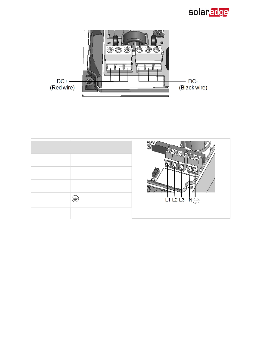
80 Replacing the DC Safety Unit
Figure 42: DC terminals
Connect the AC wires according to the labels on the ACterminal blocks, as follows:
3.
Wire type Connect to terminal
Line 1 L1
Line 2 L2
Line 3 L3
PE (grounding)
Neutral N
Figure 43: AC terminals
4. Tighten the screws of each terminal with a torque of 1.2-1.5 N*m / 0.88-1.1 lb.*ft.
5. Verify that there are no unconnected wires at the output of the DC Safety Unit and
that any unused terminal screws are tightened.
6. Connect the DC and AC wires to the DC Safety Unit. Refer to
the Strings to the Inverter
on page 30.
Connecting the AC and
7. Ensure proper cable entry sealing; inspect the entire cable run and use standard
sealants to avoid water penetration.
-Three Phase System Installation Guide MAN-01-00505-1.2
Page 82
Appendix F: Replacing and Adding System Components 81
Adding, Removing, or Replacing Power Optimizers
1. Turn OFF the inverter ON/OFF/P switch, and wait until the green LED is blinking ,
indicating that the DC voltage is safe (<50V), or wait five minutes before continuing
to the next step.
2. Disconnect the AC to the inverter by turning OFF the circuit breakers on the
distribution panel.
3. Turn OFF the DC Safety Unit (if applicable).
4. Disconnect and connect the necessary power optimizers.
5. Perform pairing and other procedures described in
Configuring the System Using the Inverter SetApp
which power optimizers were added or from which power optimizers were removed.
6. In the monitoring platform, use the Replace button in the logical
layout tab (in site Admin). Replace the serial number of the removed
power optimizer with the serial number of the newly installed power
optimizer. Refer to https://www.solaredge.com/sites/default/files/se-
monitoring-portal-site-admin.pdf
Activating, Commissioning and
on page 35 on all inverters to
Three Phase System Installation Guide MAN-01-00505-1.2
Page 83
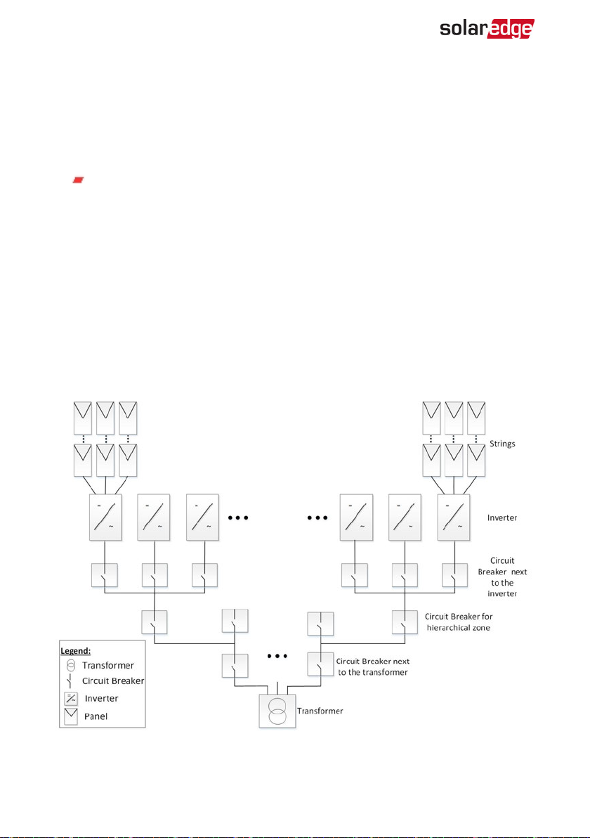
82 Appendix G: Determining the Circuit Breaker Size
Appendix G: Determining the Circuit Breaker Size
Revision History
Version 1.0 February 2019: first release
Introduction
Inverters should be protected by circuit breakers. This document describes how to
determine which circuit breaker to use in three phase commercial installations.
Using Transformers in Commercial Three Phase Inverter Installations
Using transformers in a commercial installation is optional. In most cases a transformer
is used to connect the installation to the medium voltage power grid. The following
figure illustrates a typical transformer and commercial three phase inverter installation
topology.
Figure 44: Typical transformer and commercial three phase inverter installation topology
-Three Phase System Installation Guide MAN-01-00505-1.2
Page 84
Appendix G: Determining the Circuit Breaker Size 83
There are many considerations for selecting the suitable transformer and its associated
current limiting devices such as circuit breakers and fuses. The considerations must
include at least the following:
The transformer should be designed for a typical PV system production profile:
high daytime loads with no loads at night.
The current limiting devices should protect the electrical circuits and the
inverters from the excess current created by an overload, or a short circuit. If a
short circuit or other overcurrent occurs, the current limiting devices should
block the current flow to the circuit, thus preventing damage to the electrical
circuits and the inverters.
The circuit breakers and the fuses should comply with the transformer
manufacturer recommendations and with the relevant sections in standards
such as IEC 60909, IEC 60364, UL 508A and NEC 2017.
Some manufacturers provide detailed information about the transformer short
circuit calculation procedure, and its effect on the selection of circuit breakers
and fuses at the different hierarchical levels of the installation topology (see
Figure 44
).
For an example of a calculation, refer to:
Guidelines on the Short Circuit Current Rating for Industrial Control Panels
Short-circuit current rating (SCCR) of industrial control panels
To ensure that the circuit breaker and fuses trip as expected, follow their
manufacturers' recommendations, especially with respect to the various derating considerations.
NOTE
Transformer procurement, installation, maintenance and support are the
responsibility of the installer. Damage to the inverter due to incorrect
transformer installation, or use of a transformer that is incompatible with the
SolarEdge system will render the SolarEdge warranty invalid.
NOTE
Transformer procurement, installation, maintenance and support are the
responsibility of the installer. Damage to the inverter due to incorrect
transformer installation, or use of a transformer that is incompatible with the
SolarEdge system will render the SolarEdge warranty invalid.
Three Phase System Installation Guide MAN-01-00505-1.2
Page 85
84 Determining the Size of an Inverter Circuit Breaker
Determining the Size of an Inverter Circuit Breaker
This section explains how to determine the rate of a circuit breaker next to an inverter.
For an example of an inverter with a circuit breaker next to it see
Ensure you have the following parameters before determining the circuit breaker size:
The inverter's maximum continuous output current as appears in the datasheet.
Factor for the installation's country. This factor is dictated by regulation,
applicable standards or common practice and is usually 1.25.
To determine the size of an inverter circuit breaker:
1. Multiply the inverter's maximum continuous output current by the factor.
For example, 40A x 1.25= 50A
2. Round up the rated size, as calculated in step 1, to the closest standard circuit
breaker size. See Circuit Breaker Criteria table below for standard sizes suitable for
SolarEdge three phase inverters.
NOTE
If the result has a decimal fraction smaller than 0.5 round it down.
3. To ensure that the selected circuit breaker trips as expected, at minimum consider
the following:
The circuit breaker rated voltage.
Temperature de-rating due to both close proximity of other circuit breakers and
the effect of ambient temperature on the distribution board.
De-rating due to permanent load.
Figure 44
.
If the de-rated current of the selected circuit breaker is lower than the maximum output
current of the inverter, consider selecting a circuit breaker that is designed for a higher
rated current, or reducing the temperature de-rating effect by increasing the distance
between adjacent circuit breakers.
NOTE
Make sure to select cables that are suitable for the environmental
conditions, the operating voltage and the selected circuit breaker.
Three or four pole circuit breakers are required. It is recommended to
use a four pole circuit breaker when applicable.
It is recommended to use a circuit breaker with tripping characteristic B
or C.
-Three Phase System Installation Guide MAN-01-00505-1.2
Page 86
Appendix G: Determining the Circuit Breaker Size 85
Table 1: Ci rcui t Br eaker Cri teria
Inverter
Max. Continuous Output Current
(per Phase)
Recommended Circuit Breaker
SE12.5K 20A 25A
SE14.4KUS 40A 50A
SE15K 23A 32A
SE16K 25.5A 32A
SE17K 26A 32A
SE25K 38A 50A
SE27.6K 40A 50A
SE30K 36.5A 50A
SE33.3K 40A 50A
SE43.2KUS 120A 150A
SE50K 76A 100A
SE55K 80A 100A
SE66.6K 80A 100A
SE66.6KUS 80A 100A
SE75K 120A 150A
SE82.8K 120A 150A
SE100K 120A 150A
SE100KUS 120A 150A
Three Phase System Installation Guide MAN-01-00505-1.2
Page 87
86 Technical Specifications - Three Phase Inverters (Europe &APAC)
Technical Specifications - Three Phase Inverters
(Europe &APAC)
SE4K - SE12.5K
SE4K SE5K SE7K SE8K SE9K SE10K SE12.5K Unit
Output
Rated AC power
output
Maximum AC power
output
AC Output Line
Connections
AC output voltage –
line to line / line to
neutral (nominal)
AC output voltage
range
AC frequency 50/60 ± 5 Hz
Maximum
continuous output
current (per phase)
Maximum
continuous
overcurrent
protection
Residual current
detector / Residual
Current step detector
Grid supported –
three phase
Inrush current AC
(Peak/Duration)
Maximum output
fault current
Power factor range 1 (adjustable from -0.9 to +0.9)
(1)
4000
4000 5000 7000 8000 9000 10000 12500 VA
5000 7000 8000 9000 10000 12500 VA
3 phase, 4-wire / PE (L1-L2-L3-N), TN, TT
380/ 220; 400/ 230 Vac
184 – 264.5 Vac
6.5 8 11.5 13 14.5 16 20 A
6.5 8 11.5 13 14.5 16 20 A
300 / 30 mA
3 / N / PE (WYE with Neutral)
3/ 20
33 A
Aac
(rms)
/ ms
(1)
SE4K model is available in some countries; refer to the Certifications category in
http://www.solaredge.com/groups/support/downloads
-Three Phase System Installation Guide MAN-01-00505-1.2
Page 88
Technical Specifications - Three Phase Inverters (Europe &APAC) 87
SE4K SE5K SE7K SE8K SE9K SE10K SE12.5K Unit
Total harmonic
distortion
< 3%
Protective class Class I
Utility monitoring,
islanding protection,
configurable Power
Factor, country
Yes
configurable
thresholds
Overvoltage category III
Input
Maximum DC power
(Module STC)
Transformer-less,
ungrounded
Maximum input
voltage
Nominal DC input
voltage
Maximum input
current
Maximum back-feed
current
Reverse-polarity
protection
Ground-fault
isolation detection
5400 6750 9450 10800 12150 13500 16850 W
Yes
900 Vdc
750 Vdc
7 8.5 12 13.5 15 16.5 21 Adc
0 Adc
Yes
700kΩ Sensitivity
Overvoltage category II
Maximum inverter
efficiency
European weighted
efficiency
Night-time power
consumption
97.3 97.3 97.3 97.5 97.5 97.6 97.7 %
98 %
< 2.5 W
Three Phase System Installation Guide MAN-01-00505-1.2
Page 89
88 Technical Specifications - Three Phase Inverters (Europe &APAC)
SE4K SE5K SE7K SE8K SE9K SE10K SE12.5K Unit
Additional Features
Supported
communication
2 x RS485, Ethernet, Built-in GSM (Optional)
interfaces
Inverter
commissioning
RS485 Surge
Protection
Smart Energy
Management
With the SetApp mobile application using built-in Wi-Fi
station for local connection
Optional
(4)
Export Limitation
Arc Fault Protection Integrated, user configurable (according to UL1699B)
Standard Compliance
Safety IEC-62103 (EN50178), IEC-62109
Grid connection
standards
(1)
VDE 0126-1-1, VDE-AR-N-4105, AS-4777, G83 / G59
IEC61000-6-2, IEC61000-6-3, IEC61000-3-11, IEC61000-3-
Emissions
12,
FCC part15 class B
WEEE, RoHS Yes
Installation Specifications
AC output / Gland
Diameter / Wire Cross
Section
DC input
15-21 mm / Solid wire 2.5-16 mm2, Stranded wire 2.5 - 10
2
mm
2 MC4 pairs
(2)
Dimensions (WxLxH) 540 x 315 x 260 mm
Weight 33.2 kg
Operating
temperature range
(3)
Operating humidity –
non condensing
-40 - +60 °C
< 95 %
Cooling Fan (user replaceable)
(1)
For all standards refe r to the Certifications category in
http://www.solaredge.com/groups/support/downloads.
(2)
You can connect strings in parallel to a single input as long as the cumulative current does not excee d 45A.
(3)
For inverter power de-rating refer to the application note at the following link:
http://www.solaredge.com/files/pdfs/se-temperature-derating-note.pdf
(4)
Provided with the inverter in India only. For other countries an SPD plug-in can be purchased. Refer to
https://www.solaredge.com/sites/default/files/se_spd_plug_in_for_rs485_3ph_setapp_ds.pdf
-Three Phase System Installation Guide MAN-01-00505-1.2
Page 90
Technical Specifications - Three Phase Inverters (Europe &APAC) 89
SE4K SE5K SE7K SE8K SE9K SE10K SE12.5K Unit
Noise (typical)
< 50
(1)
dBA
Protection rating/
Environmental
IP65 - Outdoor and indoor
category
Maximum altitude 2000 m
Pollution degree
classification
2/3
(inside/outside)
Bracket mounted (bracket provided)
SE15K - SE33.3K
(2)
SE15K SE16K SE17K SE25K SE27.6K SE33.3K Unit
Output
Rated AC power
output
Maximum AC power
output
AC Output Line
Connections
15000 16000 17000
15000 16000 17000 25000627600 33300 VA
3 phase, 4-wire / PE (L1-L2-L3-N), TN, TT
25000
(3)
27600 33300 VA
AC output voltage –
line to line / line to
380/ 220; 400/ 230 480/277 Vac
neutral (nominal)
AC output voltage
range
184 – 264.5 244-305 Vac
AC frequency 50/60 ± 5 Hz
Maximum continuous
output current (per
phase)
23 25.5 26 38 40
40
@277V
Maximum continuous
overcurrent
23 25.5 26 38 40 40 A
protection
A
(1)
For inverters with a noise level suitable for residential environments refe r to:
http://www.solaredge.com/files/pdfs/products/inverters/se-three-phase-indoor-inverterdatasheet.pdf
(2)
The SE33.3Kmodel requires a medium voltage transformer.
(3)
24.99kVA in the UK
Three Phase System Installation Guide MAN-01-00505-1.2
Page 91
90 Technical Specifications - Three Phase Inverters (Europe &APAC)
SE15K SE16K SE17K SE25K SE27.6K SE33.3K Unit
Residual current
detector / Residual
300 / 30 mA
Current step detector
Grid supported –
three phase
Inrush current AC
(Peak/ Duration)
Maximum output
fault current
Power factor range
Total harmonic
distortion
1 (adjustable from -0.9 to
3 / N / PE (WYEwith Neutral) V
3/ 20 3.1/ 20 4.2/ 20
40 63 A
1 (adjustable from -0.8 to
+0.9)
+0.8)
< 3%
Protective class Class I
Utility monitoring,
islanding protection,
configurable Power
Factor, country
Yes
configurable
thresholds
Overvoltage category III
Input
Maximum DC power
(Module STC)
Transformer-less,
ungrounded
Maximum input
voltage
Nominal DC input
voltage
Maximum input
current
Maximum back-feed
current
Reverse-polarity
protection
20250 21600 22950 33750 37250 45000 W
Yes
900 1000 Vdc
750 840 Vdc
22 23 23 37 40 40 Adc
0 Adc
Yes
Aac
(rms) /
ms
(1)
(1)
For SE27.6K - when set to Germany Power Factor is limited to 0.9.
-Three Phase System Installation Guide MAN-01-00505-1.2
Page 92
Technical Specifications - Three Phase Inverters (Europe &APAC) 91
SE15K SE16K SE17K SE25K SE27.6K SE33.3K Unit
Ground-fault isolation
detection
700 kΩ Sensitivity
350 kΩ Sensitivity
(1)
Overvoltage category III
Maximum inverter
efficiency
European weighted
efficiency
Night-time power
consumption
97.6 97.7 98 %
98 98.3 98.1 %
< 2.5 < 4 W
Additional Features
Supported
communication
2 x RS485, Ethernet, Built-in GSM (Optional)
interfaces
Inverter
commissioning
RS485 Surge
Protection
Smart Energy
Management
With the SetApp mobile application using built-in Wi-Fi
station for local connection
Optional
(5)
Export Limitation
Arc Fault Protection Integrated, user configurable (according to UL1699B)
Rapid Shutdown
Optional
(2)
(Automatic upon AC grid disconnect)
DC Safety Unit (optional)
2-pole Disconnection N/A 1000V / 40A
DC Surge Protection N/A Type II, field replaceable
DC Fuses on Plus &
Minus
N/A Optional, 20A
Compliance N/A UTE-C15-712-1
Standard Compliance
Safety IEC-62103 (EN50178), IEC-62109, AS3100
Grid connection
standards
(3)
VDE-AR-N-4105, G59/3, AS-4777, EN 50438 , VDE 0126-
1-1, CEI-021,
BDEW, CEI-016
(4)
;
(1)
Where permitted by local regulations
(2)
Inverter with rapid shutdown part number: SExxK-RWROOBNN2; available for SE25K and SE27.6K
(3)
For all standards refe r to the Certifications category in
http://www.solaredge.com/groups/support/downloads.
(4)
Models SE25K, SE27.6Kand SE33.3K only
(5)
Provided with the inverter in India only. For other countries an SPD plug-in can be purchased. Refer to
https://www.solaredge.com/sites/default/files/se_spd_plug_in_for_rs485_3ph_setapp_ds.pdf
Three Phase System Installation Guide MAN-01-00505-1.2
Page 93
92 Technical Specifications - Three Phase Inverters (Europe &APAC)
SE15K SE16K SE17K SE25K SE27.6K SE33.3K Unit
Emissions
IEC61000-6-2, IEC61000-6-3, IEC61000-3-11, IEC61000-3-
12
WEEE, RoHS Yes
Installation Specifications
AC output / Gland
Diameter / Wire Cross
Section
DC input
(1)
DC input with DC
Safety Unit
15-21 mm / Solid wire 2.5-
16 mm2,
Stranded wire 2.5 - 10
2
mm
18-25mm / Solid wire 2.5-16
Stranded wire 2.5-10 mm
2 MC4 pairs 3 MC4 pairs
N/A
Gland diameter 5-10 mm mm
Wire cross section 0.5 - 13.5 mm
mm2,
2
Dimensions (HxWxD) 540 x 315 x 260 mm
Dimensions with
Safety Unit (HxWxD)
N/A 775 x 315 x 260 mm
Weight 33.2 45 kg
Weight with Safety
Unit
Operating
temperature range
(2)
Operating humidity –
non condensing
N/A 48 kg
-40 - +60 °C
< 95 %
Cooling Fan (user replaceable)
Noise (typical) < 50 < 55 dBA
Protection rating/
Environmental
IP65 Outdoor and indoor
category
Maximum altitude 2000 m
Pollution degree
classification (inside/
2/3
outside)
Bracket mounted (bracket provided)
2
(1)
Connection of additional strings in parallel to a single input is allowed as long as the cumulative current does not
exceed 45A.
(2)
For inverter power de-rating information, refer to the application note at the following link:
http://www.solaredge.com/files/pdfs/se-temperature-derating-note.pdf
-Three Phase System Installation Guide MAN-01-00505-1.2
Page 94
lf you have technical queries concerning our products,
please contact our support through SolarEdge service portal:
www.solaredge.com/service/support
Australia (+61) 1800 465 567
APAC (Asia Pacific)(+972) 073 240 3118
Belgium (+32)
0800-76633
Netherlands (+31) 0800-7105
China (+86) 21 6212 5536
DACH & Rest of Europe
(+49)
089 454 59730
France (+33) 0800 917410
Italy (+39) 0422 053700
Japan (+81) 03 6262 1223
New Zealand (+64) 0800 144 875
US & Canada (+1) 510 498 3200
United Kingdom (+44) 0800 028 1183
Republic of Ireland (+353) 1-800-901-575
Greece (+49) 89 454 59730
Israel (+972) 073 240 3122
Middle East &Africa
(+972)
073 240 3118
South Africa (+27) 0800 982 659
Turkey (+90) 216 706 1929
Worldwide (+972) 073 240 3118
 Loading...