

Page 1
User manual
Energy storage integrated inverter
Product Model: HYD 3K~6K-ES
Shenzhen SOFARSOLAR Co., Ltd.
Page 2

Contents
Preface............................................................................................................... II
1. HYD-ES inverter Introduction.................................................................. - 1 -
2. Safety Notes...............................................................................................- 2 -
2.1. Safety Notes....................................................................................- 2 -
2.2. Installation and Maintenance Notes................................................- 2 -
2.3. Signs on the inverter....................................................................... - 4 -
3. Installation................................................................................................. - 5 -
3.1. Product Overview........................................................................... - 5 -
3.2. Packing List.................................................................................... - 5 -
3.3. Installation Environment................................................................ - 8 -
3.4. Installation Tools.............................................................................- 8 -
3.5. Installation Position........................................................................ - 9 -
3.6. Mount HYD-ES inverter...............................................................- 10 -
4. Electrical Connection...............................................................................- 12 -
4.1. Battery Connection....................................................................... - 12 -
4.2. PV Connection..............................................................................- 13 -
4.3. Inverter logic interface connection............................................... - 14 -
4.4. CT / CAN / RS485 / NTC connection.......................................... - 17 -
4.5. Grid Connection............................................................................- 19 -
4.6. Critical Load Connection (EPS function)..................................... - 20 -
4.7. WiFi/GPRS/Ethernet module........................................................- 21 -
5. Buttons and indicator lights..................................................................... - 23 -
5.1. Buttons.......................................................................................... - 23 -
5.2. Indicator lights and status............................................................. - 23 -
6. Operation................................................................................................. - 24 -
6.1. Double Check............................................................................... - 24 -
6.2. First Time Setup (IMPORTANT!)................................................ - 24 -
6.3. Commissioning............................................................................. - 28 -
6.4. Menu............................................................................................. - 28 -
7. Troubleshooting....................................................................................... - 46 -
8. Technical Data......................................................................................... - 54 -
9. Quality Assurance....................................................................................- 57 -
Page 3

HYD 3K~6K-ES User manual
I
Notice
This manual contains important safety instructions that must be followed
during installation and maintenance of the equipment.
Save these instructions!
This manual must be considered as an integral part of the equipment. The
manual must always accompany the equipment,even when it is transferred to
another user or field.
Copyright Declaration
The copyright of this manual belongs to Shenzhen SOFARSOLAR
Co.,Ltd.Any corporation or individual should not plagiarize, partially copy or fully
copy it (including software, ect .),and no reproduction or distribution of it in any
form or by any means.All right reserved.
SOFARSOLAR reserves the right of final interpretation.This manual is subject
to change according to user’s or customer’s feedback.Please check our website at
http://www.sofarsolar.com
for latest version.
The current Version updated at 20210303.
Copyright © Shenzhen SOFARSOLAR Co., Ltd
Page 4

HYD 3K~6K-ES User manual
II
If you have any question or problem when you read the following
information, please contact Shenzhen SOFARSOLAR Co., Ltd.
Note
Preface
Outline
Please read the product manual carefully before installation,operation or
maintenance.This manual contains important safety instructions and installation
instructions that must be followed during installation and maintenance of the
equipment.
Scope
This product manual describes the installation,electrical connections,
commissioning,maintenance and troubleshooting of HYD 3K-6K-ES inverters:
HYD 3000-ES HYD 3600-ES HYD 4000-ES
HYD 4600-ES HYD 5000-ES HYD 6000-ES
Keep this manual where it will be accessible at all times.
Target Group
This manual is intended for qualified electrical technical personnel who are
responsible for inverter installation and commissioning in the PV power system and
PV plant operator.
Symbols Used
This manual is provides safety operation information and uses the symbol in
order to ensure personal and property security and property security and use
inverter efficiently when operating the inverter. You must understand these
emphasized information to avoid the personal injury and property loss.Please read
the following symbols used in this manual carefully.
Copyright © Shenzhen SOFARSOLAR Co., Ltd
Page 5
HYD 3K~6K-ES User manual
III
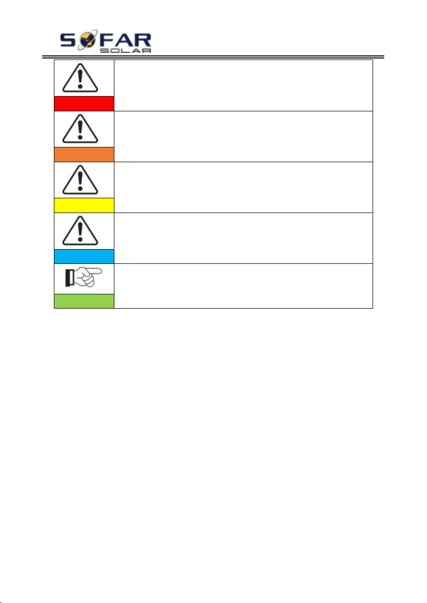
Danger indicates a hazardous situation which, if not
avoided, will result in death or serious injury.
Danger
Warning indicates a hazardous situation which, if not
avoided, could result in death or serious injury.
Warning
Caution indicates a hazardous situation which, if not
avoided, could result in minor or moderate injury.
Caution
Attention indicates potential risks which, if not
avoided, may lead to equipment fault or property damage.
Attention
Note provides tips that are valuable for the optimal
operation of the product.
Note
Copyright © Shenzhen SOFARSOLAR Co., Ltd
Page 6
HYD 3K~6K-ES User manual
- 1 -
1. HYD-ES inverter Introduction
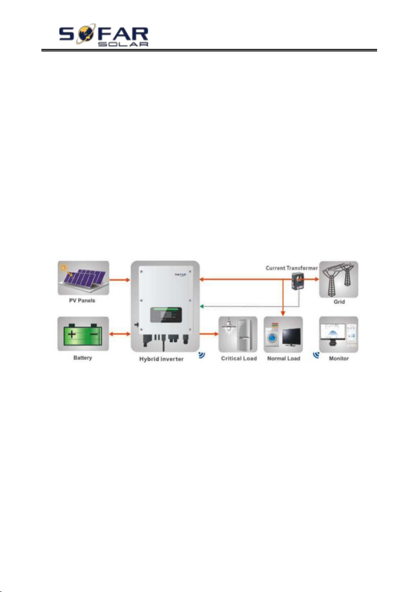
The HYD-ES hybrid inverter is used in PV system with battery storage.
Energy produced by the PV system will be optimized for maximum
self-consumption.
The HYD-ES inverter can work in auto or time-of-use (TOU) mode, charge /
discharge the battery when needed. In auto mode, the HYD-ES inverter will charge
surplus PV energy into the battery & discharge battery to supply power to local
load when PV energy is not enough.
In case of blackout, HYD-ES inverter can work in Emergency Power Supply
(EPS) mode. HYD-ES inverter will utilize power from PV panels & energy stored
in the battery to supply power to critical load.
Fig.1-1 HYD-ES inverter schematic diagram
Copyright © Shenzhen SOFARSOLAR Co., Ltd
Page 7

HYD 3K~6K-ES User manual
- 2 -
2. Safety Notes
Before installation, please make sure you read & understand this manual. The
HYD-ES inverter strictly comply with safety rules of design and testing. During the
installation, operation and maintenance, operators should abide by local safety
regulations. Improper operation may cause an electric shock or damage the
equipment and properties.
2.1. Safety Notes
Electrical installation and maintenance must be carried out by competent
electricians according to local regulations.
HYD-ES inverter can only be installed by qualified electrician, and only those
who have appropriate accreditation, as required by local authority.
Do NOT put explosives or flammable materials, e.g. gasoline, kerosene, diesel,
oil, wood slab, cotton, or rag close to batteries or HYD-ES inverter.
Disconnect AC connection first, then disconnect battery & PV(PV1&PV2),
then wait at least 5 minutes (discharge capacitors) before maintenance to
prevent electric shock.
HYD-ES inverter shall be disconnected completely (BAT, PV & AC) while
being maintained.
HYD-ES inverter can be very hot during working. Switch off HYD-ES
inverter & wait HYD-ES inverter to cool down before maintenance.
Keep children away from batteries & HYD-ES inverter.
It’s NOT allowed to open the front cover of HYD-ES inverter. This will void
the product warranty.
HYD-ES inverter damaged by improper installation/operation is NOT covered
by the product warranty.
2.2. Installation and Maintenance Notes
The battery has been charged more than 60% before being delivered and shall
be prevented from short circuit during transportation and installation.
HYD-ES inverter/batteries shall be placed in a well-ventilated place. Do not
Copyright © Shenzhen SOFARSOLAR Co., Ltd
Page 8

HYD 3K~6K-ES User manual
- 3 -
put the HYD-ES inverter/batteries in an airtight or badly ventilated place or
cabinet. This can be very harmful to system performance & service life.
Keep HYD-ES inverter/batteries away from direct sunshine. Don’t put
HYD-ES inverter/batteries close to a furnace or fire. The can lead battery to
leak even explode.
The current capacity of DC power cables (from battery to inverter) should be
at least 90A. Use short DC power cables to avoid high voltage drop & power
loss.
Use a multimeter to check the batter voltage & polarity before switching ON
batteries. Make sure connections are correct according to this manual.
Use a multimeter to check the PV voltage & polarity before switching ON PV
isolator. Make sure connections are correct according to this manual.
If you want to store the batteries without using them, they should be
disconnected from HYD-ES inverter, and be kept in a cool, dry, and ventilated
environment.
Battery maintenance operators shall have the knowledge and technical skill
for battery maintenance;
All batteries connected in parallel should be of the same model and have same
firmware version. This is a design issue needs to be considered by
designer/installer, particularly when replacing batteries or modifying an
existing energy storage system.
HYD-ES inverter is transformer-less, therefore the positive pole and negative
pole of the PV array are NOT grounded. Otherwise it will cause inverter
failure. In the PV system, all non-current carrying metal parts (such as: PV
module frame, PV rack, combiner box enclosure, inverter enclosure) should
be connected to earth.
Warning: Do not disassemble or break the battery. Its electrolyte can be toxic
and damage your skin and eyes.
Warning: follow the following rules during battery installation/maintenance.
a. Take off your watch, ring, and other metal objects.
b. Only use tools with insulated handles.
c. Wear rubber gloves and shoes.
d. Do not put tools or metals above the battery.
e. Switch off HYD-ES inverter & batteries before connecting / disconnecting
battery terminals.
Copyright © Shenzhen SOFARSOLAR Co., Ltd
Page 9
HYD 3K~6K-ES User manual
- 4 -
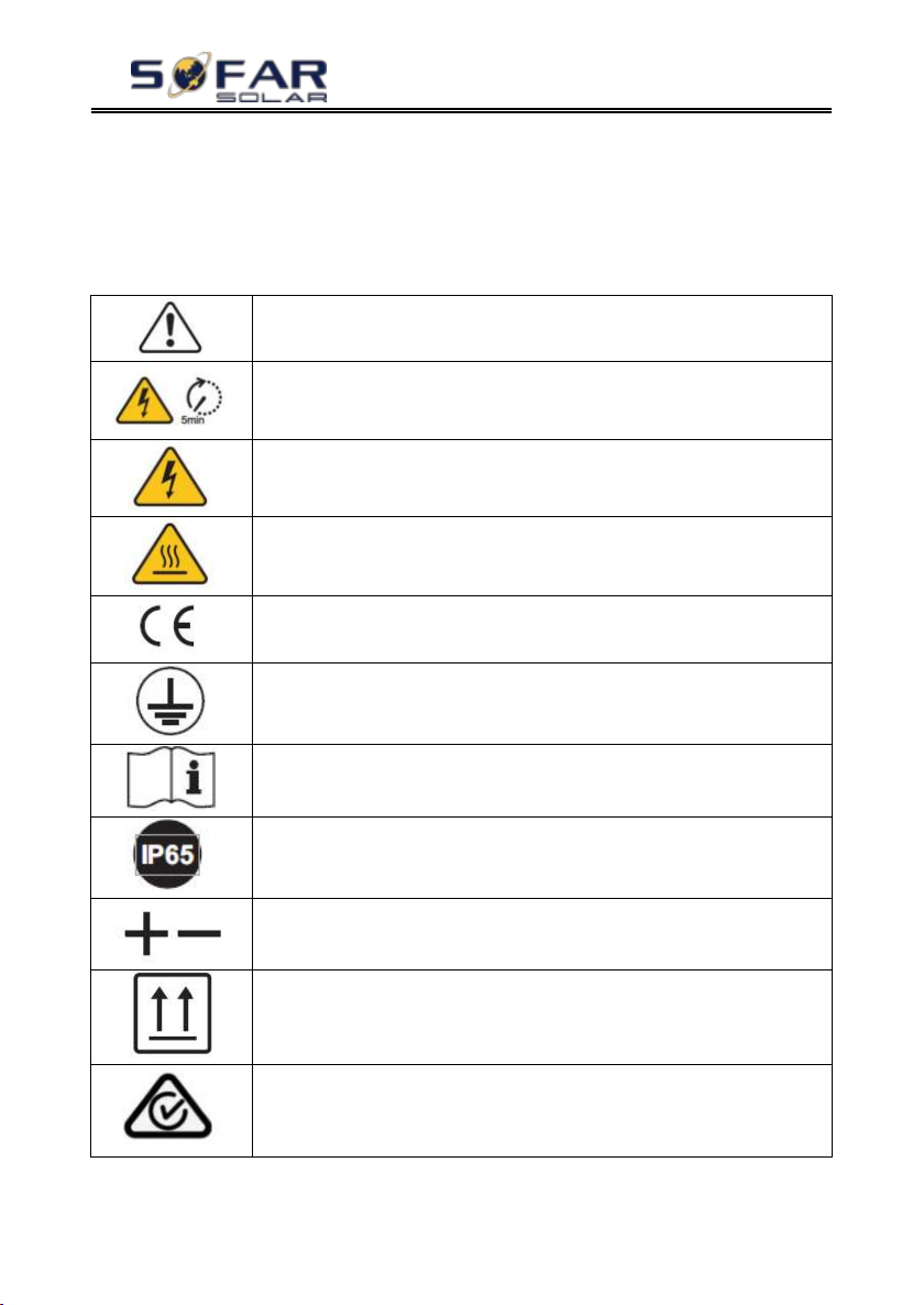
This symbol indicates a hazardous situation which could result
in injuries, if not avoided.
Risk of Electric Shock and wait at least 5 mins after switching
OFF HYD-ES inverter.
Be careful of high voltage and electric shock.
Be careful of hot surface.
Comply with the Conformity Europeanness (CE) certification.
Earth terminal.
Please read this manual before installing HYD-ES inverter.
This indicates the degree of protection of the equipment
according to IEC standard 70-1 (EN 60529 June 1997).
Positive pole and negative pole of the DC voltage (PV &
Battery).
This side up, HYD-ES inverter must always be transported,
handled and stored in such a way that the arrows always point
upwards.
RCM (Regulatory Compliance Mark)
The product complies with the requirements of the applicable
Australian standards.
f. Battery positive/negative poles should be isolated from ground.
2.3. Signs on the inverter
There are some symbols which are related to security on the inverter. Please
read and understand the content of the symbols before system installation.
Copyright © Shenzhen SOFARSOLAR Co., Ltd
Page 10
HYD 3K~6K-ES User manual
- 5 -
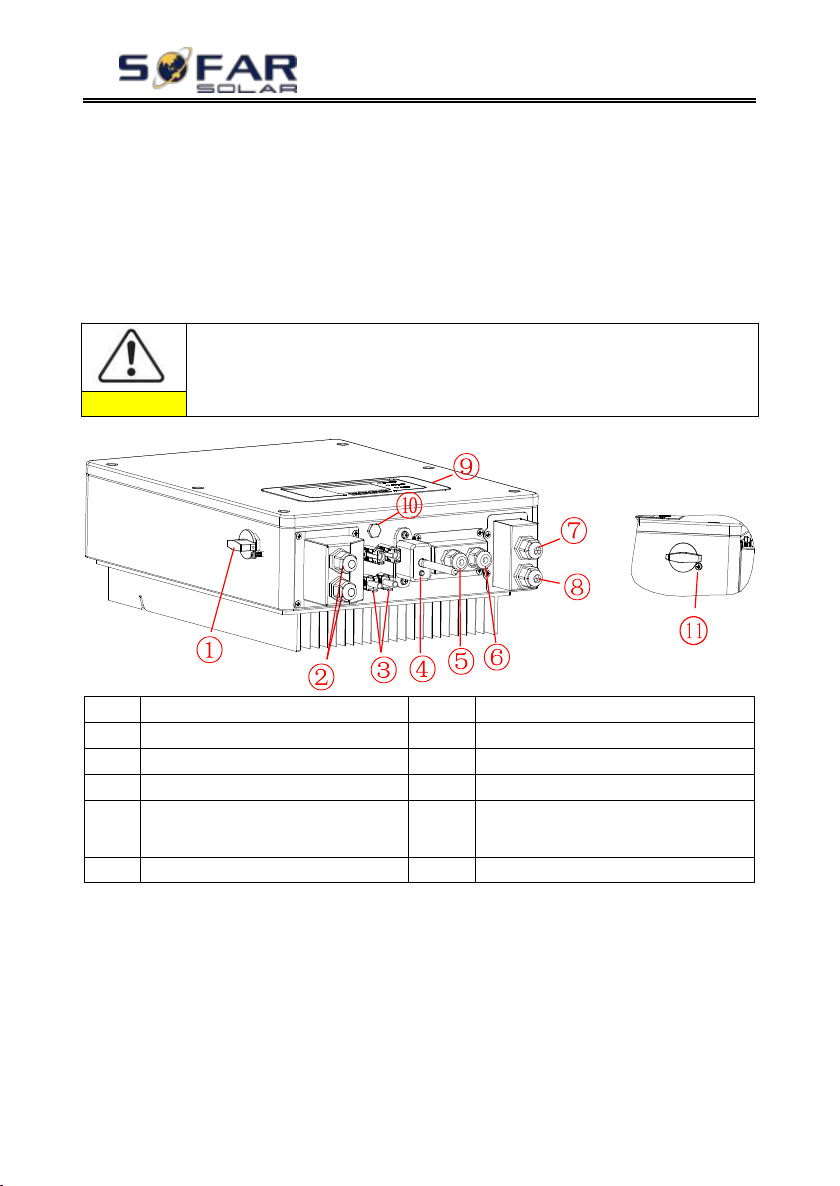
Please check the product package and fittings carefully before
installation.
Caution
1
DC switch
7
Load connection port
2
Battery input terminals
8
Grid connection port
3
PV input terminals
9
LCD
4
Wi-Fi/GPRS stick
10
Breather valve
5
BMS communication port
11*
DC switch lock(For Australian
models)
6
Current transformer port
3. Installation
3.1. Product Overview
HYD-ES inverter is 100% strictly inspected before package and delivery. It is
forbidden to put the HYD-ES inverter upside down during delivery.
Fig.3-1 HYD-ES inverter overview
*Note: Lock the screw to limit the torque of the DC switch, making it
impossible to twist the DC switch from OFF to ON, or ON to OFF.Remove the
screw before turning the DC switch from OFF to ON or ON to OFF.
3.2. Packing List
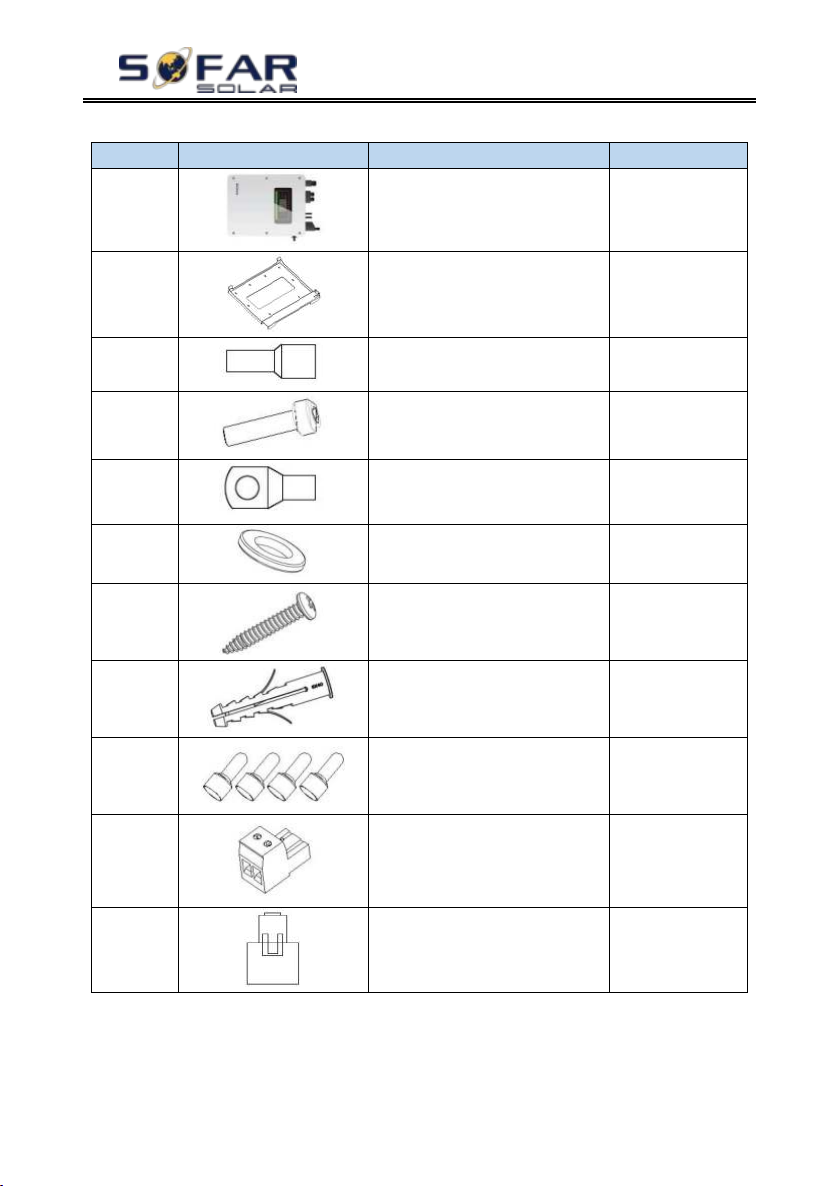
Inspect the package and fittings carefully before installation. You should have
the following fittings:
Copyright © Shenzhen SOFARSOLAR Co., Ltd
Page 11
HYD 3K~6K-ES User manual
- 6 -
NO.
Picture
Description
Quantity
1
Inverter
1pcs
2
Mounting Bracket
1pcs
3
AC terminal
6pcs
4
M5 screw
2pcs
5
Battery terminal
2pcs
6
M6 flat washer
10pcs
7
Self-tapping screw
8pcs
8
Expansion bolts
8pcs
8
Terminal cap
2pcs
9
CT terminal
3pcs
10CT1pcs
Table3-1 Components and mechanical parts that should be delivered
Copyright © Shenzhen SOFARSOLAR Co., Ltd
Page 12
HYD 3K~6K-ES User manual
- 7 -
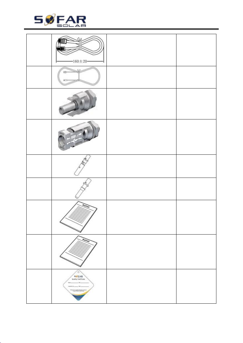
11
Communication cable
1pcs
12
NTC×1 (Long-3M)
1pcs
13
PV+ input terminal
2pcs
14
PV- input terminal
2pcs
15
Metal terminals secured
to PV+ input power
cables
2pcs
16
Metal terminals secured
to PV- input power
cables
2pcs
17
User Manual
2pcs
18
Warranty card
1pcs
19
Quality Certificate
1pcs
Copyright © Shenzhen SOFARSOLAR Co., Ltd
Page 13
HYD 3K~6K-ES User manual
- 8 -
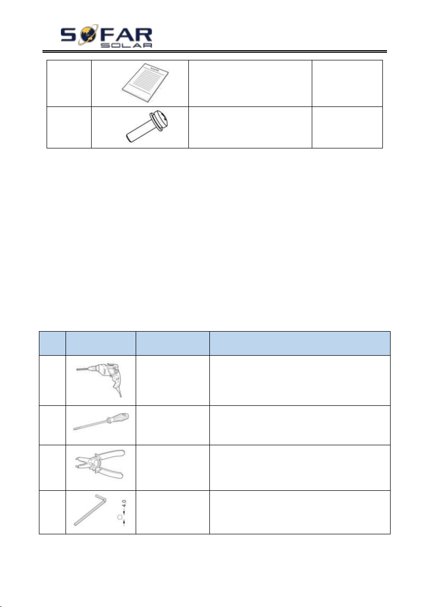
20
Outgoing inspection
report
1pcs
18
M4X14 Cross round
head triple set screw(Only for
DC switch lock
)
1pcs
No.
Tool
Model
Function
1
Hammer drill
Recommend
drill dia.6mm
Used to drill holes on the wall
2
Screwdriver
wiring
3
Wire stripper
Strip wire
4
4mm Allen Key
Turn the screw to connect rear panel with
inverter
3.3. Installation Environment
Choose a dry, clean, and tidy place, convenient for installation
Ambient temperature range: -25℃ ~ 60℃
Relative humidity: 0 ~ 100% (non-condensed)
HYD-ES inverter shall be installed in a well-ventilated place
No flammable or explosive materials close to HYD-ES inverter
The AC overvoltage category of HYD-ES inverter is category III
Maximum altitude: 2000m
3.4. Installation Tools
The following tools shall be prepared before installation:
Copyright © Shenzhen SOFARSOLAR Co., Ltd
Page 14
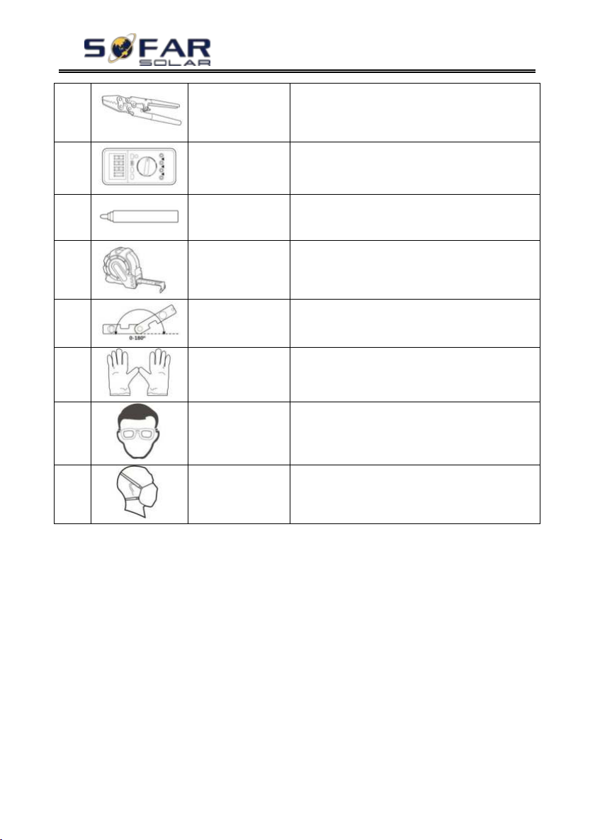
HYD 3K~6K-ES User manual
- 9 -
5
Crimping tools
Used to crimp power cables
6
Multi-meter
Used to check grounding
7
Marker pen
Used to mark signs
8
Measuring tape
Used to measure distances
9
Level
Used to ensure that the rear panel is properly
installed
10
ESD gloves
Operators wear
11
Safety goggles
Operators wear
12
Anti-dust
respirator
Operators wear
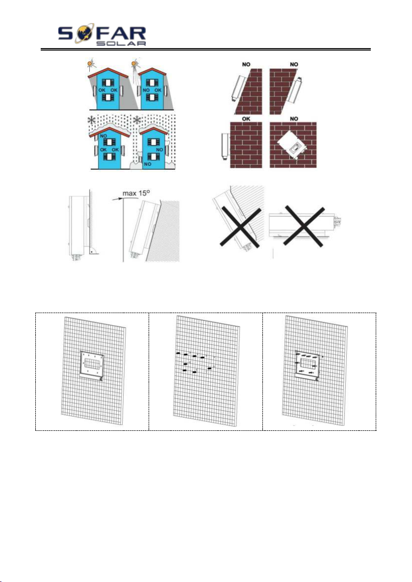
3.5. Installation Position
HYD-ES inverter should be vertically mounted (to ensure fast heat
dissipation), please choose a position without direct sunlight / snow accumulation
to install HYD-ES inverter. Please the installation position is well-ventilated.
Fig. 3-2 Installation Position of HYD-ES inverter
Copyright © Shenzhen SOFARSOLAR Co., Ltd
Page 15
HYD 3K~6K-ES User manual
- 10 -
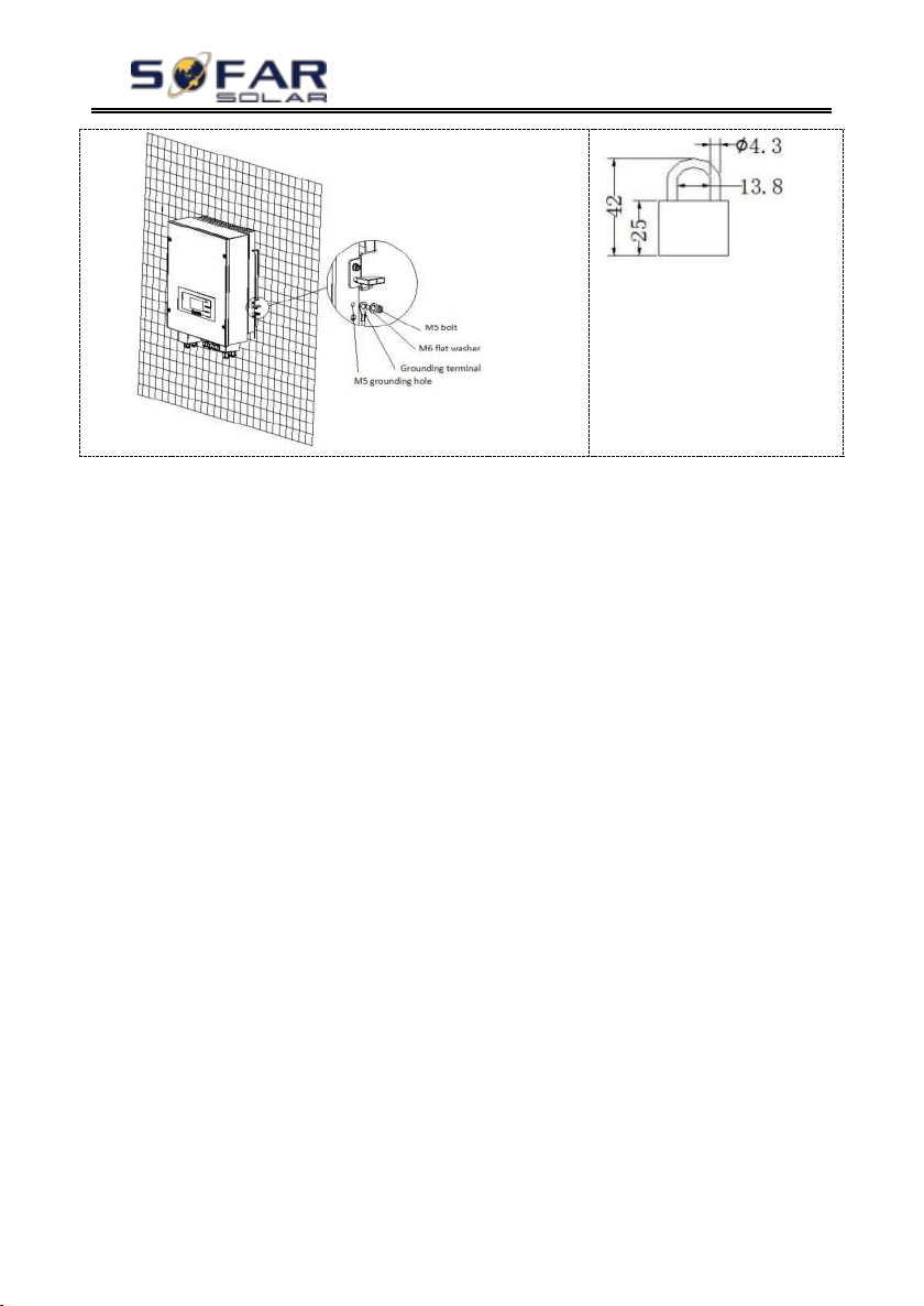
3.6. Mount HYD-ES inverter
Fig. 3-3 Mount HYD-ES inverter
Copyright © Shenzhen SOFARSOLAR Co., Ltd
Page 16
HYD 3K~6K-ES User manual
- 11 -
Step 1: Put the mounting bracket properly on the wall, mark these 8 drill
holes using a marker pen. Drill 8 holes (drill bit 6mm) on the wall.
Step 2: Insert the expansion screw vertically into the hole, note the insertion
depth. (not too shallow or too deep)
Step 3: Fix the mounting bracket on the wall using bolts & flat washers.
Step 4: Put HYD-ES inverter on the mounting bracket.
Step 5: Earth HYD-ES inverter using the grounding hole on the heat sink.
Step 6: OPTIONAL: you can lock HYD-ES inverter to the mounting bracket.
Copyright © Shenzhen SOFARSOLAR Co., Ltd
Page 17
- 12 -
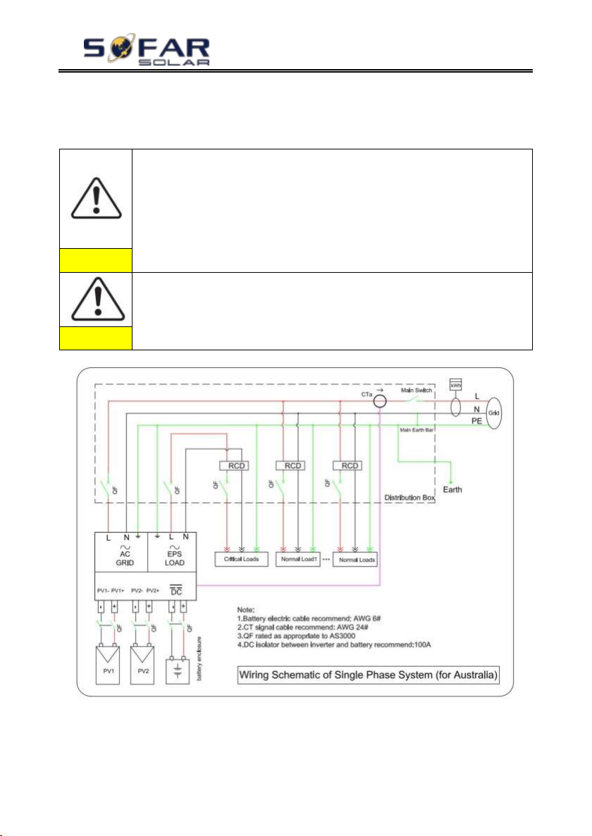
High voltages in power conversion circuits. Lethal hazard of electric
shock or serious burns.
All work on the PV modules, inverters, and battery systems must be
carried out by qualified personnel only.
Wear rubber gloves and protective clothing (protective glasses and
boots) when working on high voltage/high current systems such as
INVERTER and battery systems.
Caution
HYD-ES inverter is intended to be used in PV system with battery
storage. If not used as intended, the protection provided by the equipment
may be impaired.
Caution
Fig. 4-1 Electrical connections
HYD 3K~6K-ES User manual
4. Electrical Connection
4.1. Battery Connection
Fig. 4-2 Battery connection (Measure battery wires polarity/voltage before connection)
Copyright © Shenzhen SOFARSOLAR Co., Ltd
Page 18
HYD 3K~6K-ES User manual
- 13 -
Cross-Sectional Area (mm2)
External Cable Diameter(mm2)
Range
Recommended Value
4.0~6.0
4.0
4.5~7.8
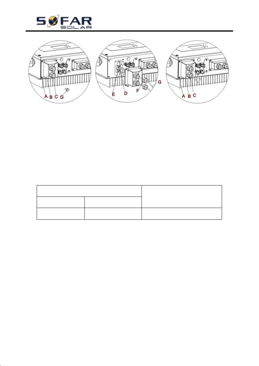
Step 1: Loosen 4 screws (A) using a screwdriver (Fig. 4-2);
Step 2: Remove the waterproof cover (B), loosen the cable gland (C), and
then remove the stopper (G);
Step 3: Route the battery wires (F) through the cable gland, then connect
battery wires using OT terminal (E);
Step 4: Fasten the waterproof cover using 4 screws.
4.2. PV Connection
Table4-1 Recommended DC input cable specifications
Procedure:
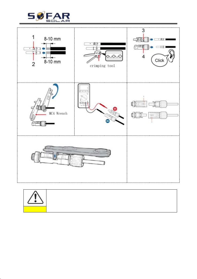
Step 1 Prepare PV positive and negative power cables.
Step 2 Insert crimped PV positive and negative power cables into
corresponding PV connectors.
Step 3 Make sure the DC voltage of each PV string is less than 600V DC and
polarities of PV power cables are correct. Insert the positive and negative
connectors into HYD-ES inverter until you hear a "click" sound, as shown in
Fig.4-3③.
Fig.4-3 Connect Battery&PV connectors
Copyright © Shenzhen SOFARSOLAR Co., Ltd
Page 19
HYD 3K~6K-ES User manual
- 14 -
1. Positive metal contact
2. Negative metal contact ①
②
3. Positive connector
4. Negative connector ③
④
⑤
⑥
Disconnect PV connectors
⑦
Before removing the PV positive and negative connectors, ensure
that the DC SWITCH is OFF.
Caution
4.3. Inverter logic interface connection
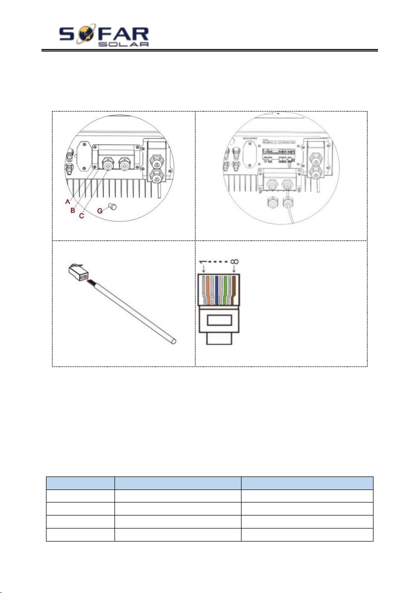
Step 1: Loosen 4 screws (A) using a screwdriver (fig. 4-4①);
Step 2: Remove the waterproof cover (B),Loosen the cable gland (C), and
then remove the stopper (G);
Step 3: Press the wire terminals in color sequence;
Copyright © Shenzhen SOFARSOLAR Co., Ltd
Page 20
HYD 3K~6K-ES User manual
- 15 -
①
②
③
1.White and orange
2.Orange
3.White and green
4.Blue
5.White and blue
6.Green
7.White and brown
8.Brown
④
Pin NO.
Color
Function
1
White and orange
DRM1/5
2
Orange
DRM2/6
3
White and green
DRM3/7
4
Blue
DRM4/8
Step 4: Route Cable terminal through the cable gland, Insert the
communication cable into the RJ45 connector;
Step 5: Fasten the waterproof cover using 4 screws.
Fig.4-4 Logic interface
The logic interface pin definitions and circuit connections are as follows:
Logic interface pin are defined according to different standard requirements
(a)Logic interface for AS/NZS 4777.2:2015, also known as inverter demand
response modes (DRMs).
The inverter will detect and initiate a response to all supported demand
response commands within 2 s. The inverter will continue to respond while the
mode remains asserted.
Table 4-2 Function description of the DRMs terminal
Copyright © Shenzhen SOFARSOLAR Co., Ltd
Page 21
HYD 3K~6K-ES User manual
- 16 -
5
White and blue
DRM0
6
Green
RefGen
7
White and brown
Pin7&Pin8 short internal
8
Brown
Pin NO.
Pin name
Description
Connected to (RRCR)
1L1Relay contact 1 input
K1 - Relay 1 output
2L2Relay contact 2 input
K2 - Relay 2 output
3L3Relay contact 3 input
K3 - Relay 3 output
4L4Relay contact 4 input
K4 - Relay 4 output
5NCNot Connected
Not Connected
6
G
GND
Relays common node
7NCNot Connected
Not Connected
8NCNot Connected
Not Connected
L1L2L3
L4
Active Power
Cos(φ)
10000%
1
010030%
1
001060%
1
0001100%
1
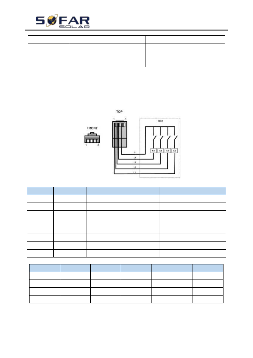
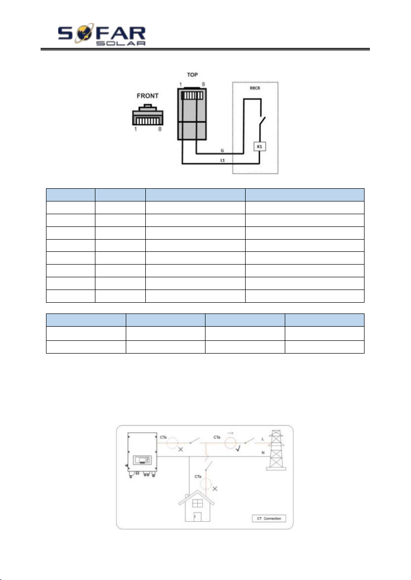
(b)Logic interface for VDE-AR-N 4105:2018-11, is in order to control
and/or limit the inverter’s output power.
The inverter can be connected to a RRCR (Radio Ripple Control Receiver) in
order to dynamically limit the output power of all the inverters in the installation.
Fig.4-5 Inverter – RRCR Connection
Table 4-3 Function description of the terminal
Table 4-4 The inverter is preconfigured to the following RRCR power levels,close is 1, open is 0
(c)Logic interface for EN50549-1:2019, is in order to cease active power
output within five seconds following an instruction being received at the input
interface.
Copyright © Shenzhen SOFARSOLAR Co., Ltd
Page 22
HYD 3K~6K-ES User manual
- 17 -
Pin NO.
Pin name
Description
Connected to (RRCR)
1L1Relay contact 1 input
K1 - Relay 1 output
2NCNot Connected
Not Connected
3NCNot Connected
Not Connected
4NCNot Connected
Not Connected
5NCNot Connected
Not Connected
6GGND
K1 - Relay 1 output
7NCNot Connected
Not Connected
8NCNot Connected
Not Connected
L1
Active Power
Power drop rate
Cos(φ)
1
0%
<5 seconds
1
0
100%/1
Fig.4-6 Inverter – RRCR Connection
Table 4-5 Function description of the terminal
Table 4-6 The inverter is preconfigured to the following RRCR power levels,close is 1, open is 0
4.4. CT / CAN / RS485 / NTC connection
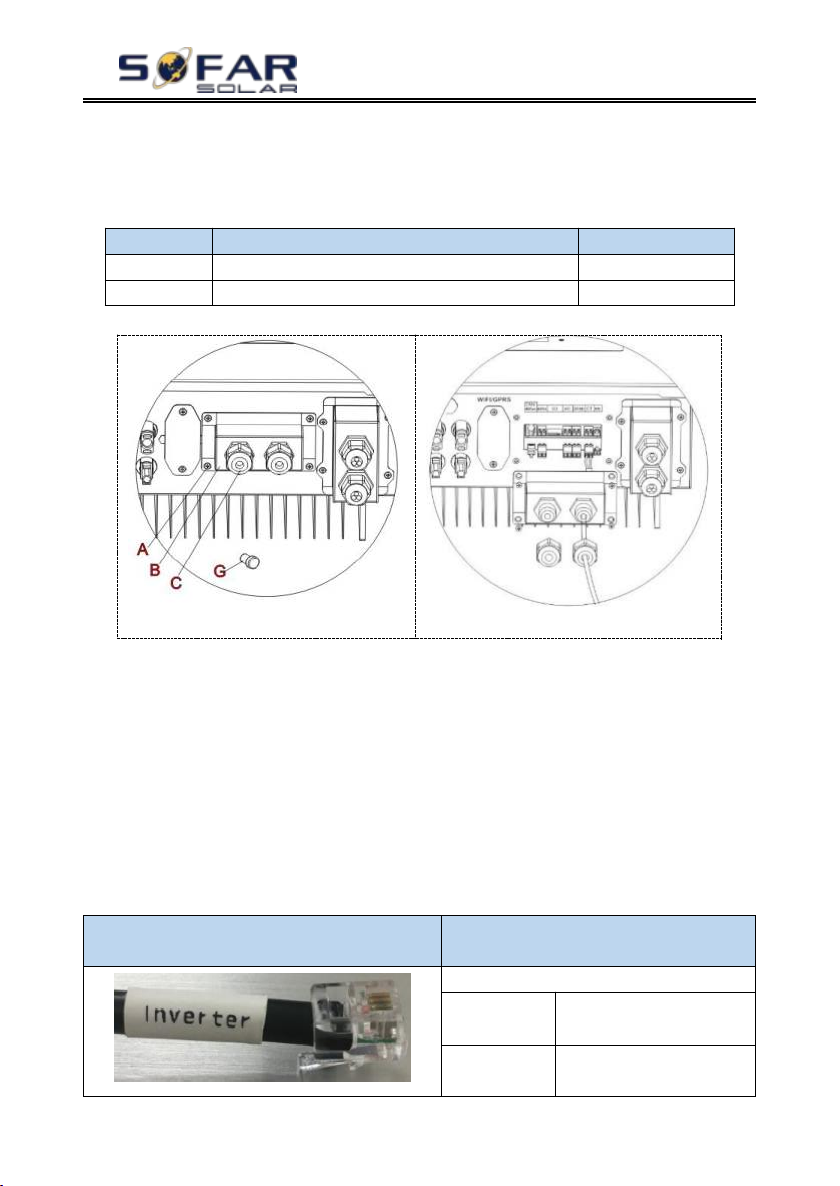
CT (Current transformer) can measure the value and direction of AC current.
Refer to Fig.4-7 for the correct connection of CTa.
Fig. 4-7 CTa connection
Copyright © Shenzhen SOFARSOLAR Co., Ltd
Page 23
HYD 3K~6K-ES User manual
- 18 -
CT wire
Extension cable (network cable)
HYD-ES inverter
Red
Orange / white orange / brown / white brown
CT+
Black
Green / white green / blue / white blue
CT-
①
②
Communication cable between battery &
HYD-ES inverter
CAN communication
HYD-ES inverter
CAN port
CANH---pin1
CANL---pin2
RS485 port
485A----pin3
485B----pin4
Step 1: Refer to Fig. 11 for correct position of CTa. Wrap the CT around L
wire of incoming mains, make sure that the CT arrow direction is “home → grid”.
Step 2: You can use network cable & terminal caps to extend CT wires if
necessary, the maximum CT cable length is 200m.
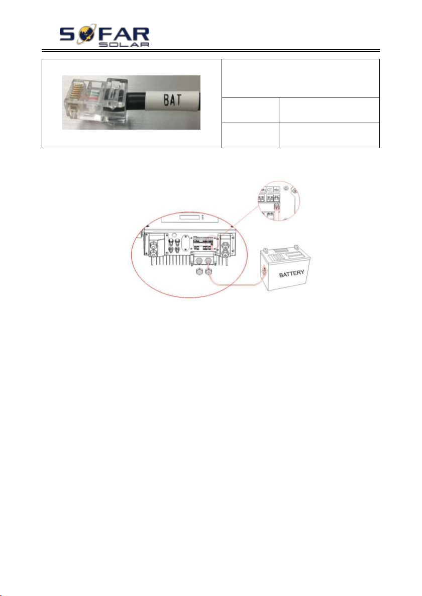
Fig.4-8 CT / CAN / RS485 / NTC connection
Step 3: Loosen 4 screws (part A) using a screwdriver (Fig.4-8①)
Step 4: Remove the waterproof cover (part B), loosen the cable gland (part C),
then remove the stopper (part G)
Step 5: Route CT cable through the cable gland, connect CT cable to CT
terminal, then insert CT terminal into corresponding ports.
Step 6: One communication cable (between battery BMS & HYD-ES inverter)
is provided in the HYD-ES inverter accessory bag. One inverter end, one BAT end.
Route the communication cable (inverter end) through the cable gland, insert
the 4P4C connector to HYD3000/4000/5000/6000-ES CAN port. Insert the 8P8C
connector (BAT end) to PYLONTECH battery CAN port.
Copyright © Shenzhen SOFARSOLAR Co., Ltd
Page 24
HYD 3K~6K-ES User manual
- 19 -
PYLONTECH US2000 PLUS /
US3000
AMASS Battery
CAN Port
CANH---pin4
CANL---pin5
RS485 port
485A----pin2 & pin7
485B----pin1 & pin8
Step 7: Connect NTC for lead acid batteries only:
Fig. 4-9 NTC connection
Step 8: Fasten the waterproof cover using 4 screws.
4.5. Grid Connection
Sofarsolar has already integrated RCMU (residual current monitoring unit)
inside inverter, If an external RCD is required, a type-A RCD with rated residual
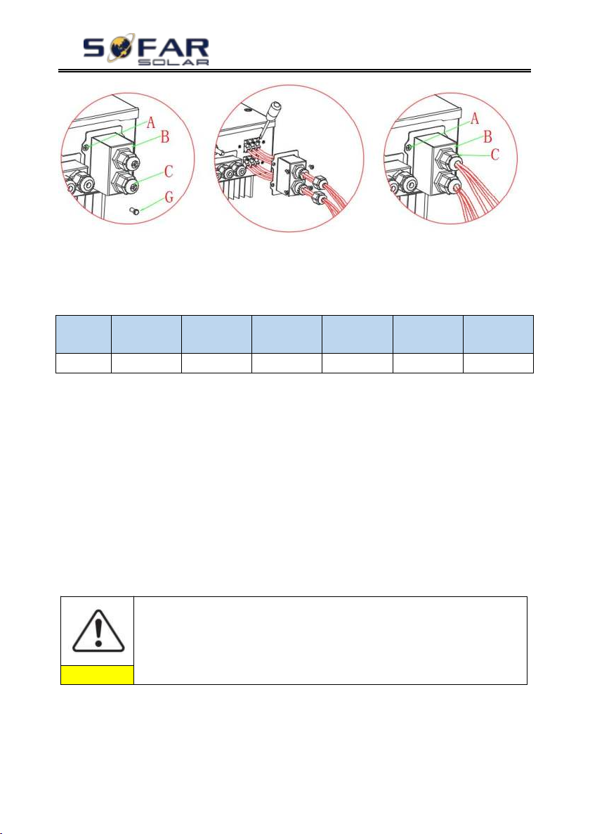
current of 100mA or higher is suggested.
Step 1: Loosen 4 screws (part A) using a screwdriver (fig. 4-10)
Step 2: Remove the waterproof cover (part B), loosen the cable gland (part C),
then remove the stopper (part G)
Step 3: Route a 3-core cable through GRID cable gland, then connect 3 wires
to corresponding terminal blocks. (BROWN – L, BLUE – N, YELLOW/GREEN –
PE)
Step 4: Fasten the waterproof cover using 4 screws.
Fig.4-10 Grid & Load connection
Copyright © Shenzhen SOFARSOLAR Co., Ltd
Page 25
HYD 3K~6K-ES User manual
- 20 -
Model
HYD
3000-ES
HYD
3600-ES
HYD
4000-ES
HYD
4600-ES
HYD
5000-ES
HYD
6000-ES
Breaker
25A
25A
32A
32A
32A
32A
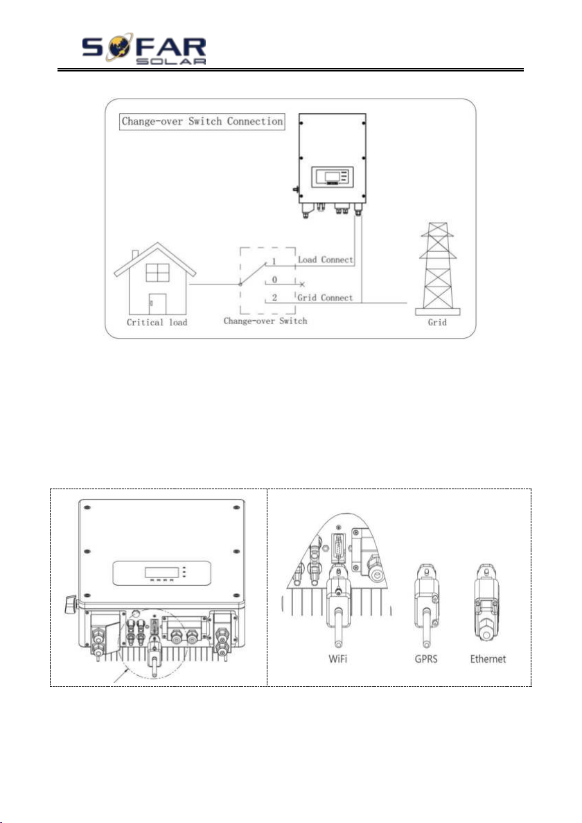
The changeover switch is necessary.
While checking/repairing critical load, make sure change-over switch
is at position 0.
While checking/repairing HYD-ES inverter, make sure change-over
switch is at position 0 & HYD-ES inverter is disconnected from grid.
Caution
Context
All the AC output cables used for the inverters are outdoor three-core cables.
To facilitate the installation, use flexible cables. The following table lists the
recommended specifications for the Breaker.
4.6. Critical Load Connection (EPS function)
Critical load: in case of grid outage, if EPS function is enabled, HYD-ES
inverter will work in EPS (Emergency Power Supply) mode, utilize the PV power
& energy stored in the battery to supply power to critical load via LOAD
connection port.
LOAD connection port is only for critical load connection. The power of
critical loads must be less than 3000VA.
The connection procedure of LOAD port is the same as grid connection (Fig.
18).
Change-over positions
Under normal conditions: change-over switch is at position 1. HYD-ES
inverter can supply power to critical load in case of blackout.
If the HYD-ES inverter is faulty, manually change the switch to position 2.
Grid will supply power to critical load.
Copyright © Shenzhen SOFARSOLAR Co., Ltd
Page 26
HYD 3K~6K-ES User manual
- 21 -
Fig. 4-11 Change-over Switch connections
4.7. WiFi/GPRS/Ethernet module
NOTE:GPRS and Ethernet is optional and is not suitable for all
countries .
Step1: Remove WiFi/GPRS/Ethernet waterproof cover using screw driver.
Step2: Install WiFi/GPRS/Ethernet module.
Stpe3: Fasten WiFi/GPRS/Ethernet module using screws.
The operation information (generated energy, alert, operation status) of the
inverter can be transferred to PC or uploaded to the server via WiFi /GPRS/
Ethernet. You can register on the website.
http://www.solarmanpv.com/portal/Register/Regi_Pub.aspx
Copyright © Shenzhen SOFARSOLAR Co., Ltd
Page 27

HYD 3K~6K-ES User manual
- 22 -
Using the WiFi/GPRS/Ethernet S/N number(NOTE3), then you can login the
website: http://www.solarmanpv.com/portal/LoginPage.aspx to remote monitors the
inverter.
Note1:S/N number of the WiFi/GPRS/Ethernet module is located on the side.
Note2:Specific use methods of WiFi/GPRS/Ethernet can refer to the operation
manual of WiFi/GPRS/Ethernet.
Copyright © Shenzhen SOFARSOLAR Co., Ltd
Page 28
HYD 3K~6K-ES User manual
- 23 -
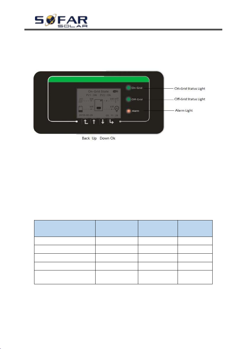
Status of HYD inverter
On Grid
Green light
Off-Grid
Green light
Alarm
Red light
On-grid
ON
Standby (On-Grid)
Flashing
Off-Grid
ON
Standby (Off-Grid)
Flashing
Alarm
ON
5. Buttons and indicator lights
Fig 5-1. Buttons and indicator lights
5.1. Buttons
Press “back” to the previous screen or enter the main interface.
Press “up” to the upper menu option or value plus 1.
Press “down” to the lower menu option or value minus 1.
Press “ok” to select the current menu option or switch to the next digit.
5.2. Indicator lights and status
Copyright © Shenzhen SOFARSOLAR Co., Ltd
Page 29

HYD 3K~6K-ES User manual
- 24 -
6. Operation
6.1. Double Check
Please double check the following before operation.
1. HYD-ES inverter is firmly fastened to the mounting bracket on the wall;
2. PV+/PV- wires are firmly connected, polarity and voltage are correct;
3. BAT+/BAT- wires are firmly connected, polarity and voltage are correct;
4. DC isolator is correctly connected between battery & HYD-ES inverter, DC
isolator: OFF;
5. GRID / LOAD cables are firmly / correctly connected;
6. AC circuit breaker is correctly connected between HYD-ES inverter GRID
port & GRID, circuit breaker: OFF;
7. AC circuit breaker is correctly connected between HYD-ES inverter LOAD
port & critical load, circuit breaker: OFF;
8. For lithium battery, please ensure that the communication cable has been
correctly connected;
9. For the lead-acid battery, please ensure that the NTC wire has been correctly
connected.
6.2. First Time Setup (IMPORTANT!)
IMPORTANT: PLEASE FOLLOW THE FOLLOWING PROCEDURE to
switch ON HYD-ES inverter
1. Make sure there’s no power generation in HYD-ES inverter’s phase.
2. Turn ON DC switch.
3. Switch ON the battery. Turn ON DC isolator between battery & HYD-ES
inverter.
4. Turn ON AC circuit breaker between the HYD-ES inverter GRID port &
GRID.
5. Turn ON AC circuit breaker between the HYD-ES inverter LOAD port &
critical load.
6. HYD-ES inverter should start to operate now.
You need to set the following parameters before HYD-ES inverter starts to
Copyright © Shenzhen SOFARSOLAR Co., Ltd
Page 30
HYD 3K~6K-ES User manual
- 25 -
1)Set system time
8)*Set min discharge voltage
2)Set country
9)*Set max discharge current
3)Select battery type
10)*Set min protect voltage
4)*Set battery capacity
11)*Set discharge depth
5)*Set max charge voltage
12)*Set empty discharge voltage
6)*Set max charge current
13)*Set full charge voltage
7)*Set max protect voltage
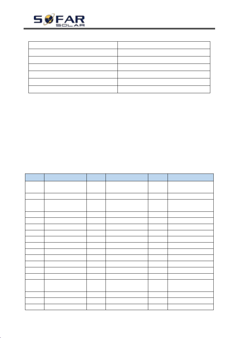
code
country
code
country
code
country
00
Germany VDE
AR-N4105
21
Sweden
42
LV-Range-50HZ
01
CEI0-21 Internal
22
Europe General
43
EU EN50549
02
Australia
23
CEI0-21
External
44
South Africa
03
Spain RD1699
24
Cyprus
45
AU-WA
04
Tuekey
25
India
46
Dubai DEWG
05
Denmark
26
Philippines
47
Dubai DEWG MV
06
Greece Continent
27
New Zealand
48
Taiwan
07
Netherland
28
Brazil
49
AU-VIC
08
Belgium
29
Slovakia VSD
100
AU- SA
09
UK-G99t
30
Slovakia SSE
101
AU-QLD
10
China
31
Slovakia ZSD
102
AU-VAR
11
France
32
CEI0-21 In Areti
103
AUSGRID
12
Poland
33
Ukraine
104
Horizon
13
Germany BDEW
34
Brazil
14
Germany VDE
0126
35
Mexico
15
Italy CEI0-16
36
FAR Arrete23
16
UK-G98
37
Denmark Tr322
17
Greece island
38
Wide-Range-60
operate.
Note: 4)* to 13)* settings are only for DEFAULT battery type.
1)Set system time
System time format is “20YY-MM-DD-HH-MM-SS”, press “up” or
“down” to change the 1stdigit, press “ok” to switch to next digit, press “ok”
to complete setting. When system time setting is complete, “Set country” will pop
up.
2)Set country
Press “up” or “down” to select a country, press “ok” to complete the
country setting. When country setting is complete, “Set battery type” will pop up.
Copyright © Shenzhen SOFARSOLAR Co., Ltd
Page 31
HYD 3K~6K-ES User manual
- 26 -
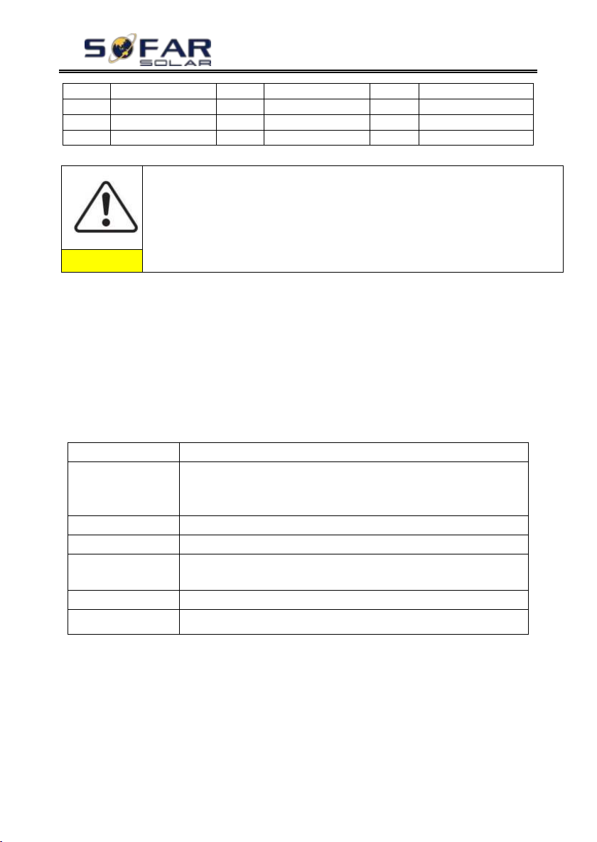
HZ
18
EU EN50438
39
Ireland EN504
19
IEC EN61727
40
Thailand PEA
20
Korea
41
Thailand MEA
It’s very important to make sure that you have selected the correct
country code according to requirements of local authority.
Please consult qualified electrical engineer or personnel from electrical
safety authorities about this.
Shenzhen SOFARSOLAR Co., Ltd. is not responsible for any
consequences arising out of incorrect country code selection.
Caution
MENU
Compatible Batteries
1.PYLON
PYLONTECH US2000 PLUS / US2000B/US3000
Note: Please confirm with representative of PYLONTECH that
your battery is compatible with HYD3000/4000/5000/6000-ES
2. DARFON--NC
DARFON 14S31P ESS--NC
3.DEFAULT
LEAD ACID / LEAD CRYSTAL / AQUION battery
4. General
Lithium
All batteries that comply with SOFAR’S BMS CAN
communication protocol.
5. Alpha. ESS
M48112-P / SMILE-BAT
6. SOLTARO
SL-3KWH / SL-1KWH
3)Select battery type
Press “up” or “down” to select your battery type, then press “ok” to
complete the battery type setting.
If you’re using “1. PYLON”, “2. DARFON”, “4. General Lithium”,
“5. Alpha. ESS” or “6. SOLTARO” battery types, congratulations, inverter’
s first-time setup is complete. Please press “ok” to enter the main interface.
But if you’re using “3. DEFAULT” battery type. We need more information
regarding your battery.
4)*Set battery capacity (only for DEFAULT battery type)
Press “up” or “down” to change the 1stdigit, press “ok” to switch to
next digit. After changing the battery capacity per your battery specification, press
“ok”, then “Set max charge voltage” will pop up.
5)*Set max charge voltage (only for DEFAULT battery type)
Press “up” or “down” to change the 1stdigit, press “ok” to switch to
next digit. After changing max charge voltage per your battery specification, press
Copyright © Shenzhen SOFARSOLAR Co., Ltd
Page 32

HYD 3K~6K-ES User manual
- 27 -
“ok”, then “Set max charge current” will pop up.
6)*Set max charge current (only for DEFAULT battery type)
Press “up” or “down” to change the 1stdigit, press “ok” to switch to
next digit. After changing the max charge current per your battery specification,
press “ok”, then “Set max protect voltage” will pop up.
7)*Set max protect voltage (only for DEFAULT battery type)
Press “up” or “down” to change the 1stdigit, press “ok” to switch to
next digit. After changing the max protect voltage per your battery specification,
press “ok”, then “Set min discharge voltage” will pop up.
8)*Set min discharge voltage (only for DEFAULT battery type)
Press “up” or “down” to change the 1stdigit, press “ok” to switch to
next digit. After changing the min discharge voltage per your battery specification,
press “ok”, then “Set max discharge current” will pop up.
9)*Set max discharge current (only for DEFAULT battery type)
Press “up” or “down” to change the 1stdigit, press “ok” to switch to
next digit. After changing the max discharge current per your battery specification,
press “ok”, then “Set min protect voltage” will pop up.
10)*Set min protect voltage (only for DEFAULT battery type)
Press “up” or “down” to change the 1stdigit, press “ok” to switch to
next digit. After changing the min protect voltage per your battery specification,
press “ok”, then “Set discharge depth” will pop up.
11)*Set discharge depth (only for DEFAULT battery type)
Press “up” or “down” to change the 1stdigit, press “ok” to switch to
next digit. After changing the discharge depth per your battery specification, press
“ok”, then “Set empty discharge voltage” will pop up.
12)*Set empty discharge voltage (only for DEFAULT battery type)
Press “up” or “down” to change the 1stdigit, press “ok” to switch to
next digit. After changing the empty discharge voltage per your battery
specification, press “ok”, then “Set full charge voltage” will pop up.
13)*Set full charge voltage (only for DEFAULT battery type)
Press “up” or “down” to change the 1stdigit, press “ok” to switch to
next digit. After changing the full charge voltage per your battery specification,
press “ok”.
Copyright © Shenzhen SOFARSOLAR Co., Ltd
Page 33
HYD 3K~6K-ES User manual
- 28 -
Main Interface
Press “down”
1.Grid(V)
2.AC Current(A)
3.Frequency
4.Batt(V)
5.Batt Chrg Curr.
6.Batt DisChrg Curr.
7.State of Charge
8.Batt Cycles
Congratulations, HYD 3K~6K-ES’s first-time setup is complete. Please press
“ok” to enter the main interface.
6.3. Commissioning
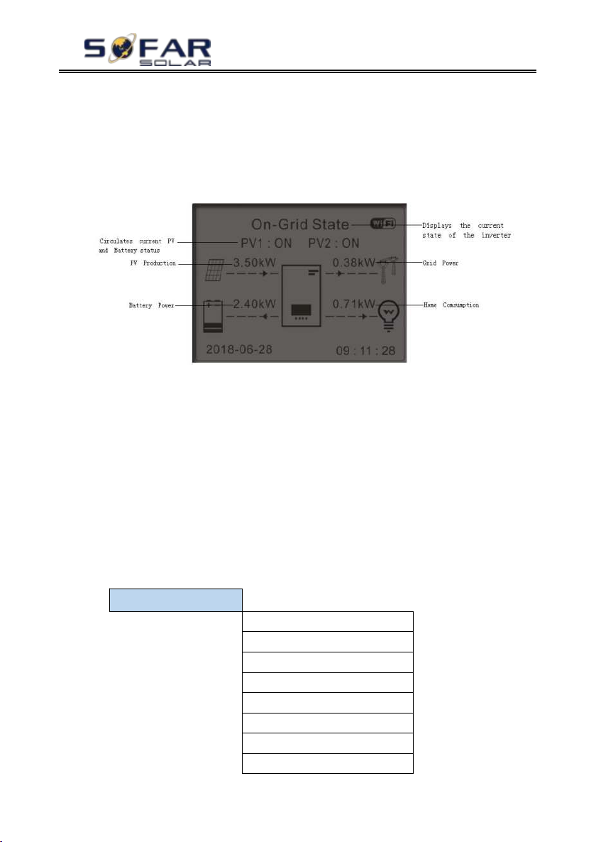
Fig 6-1. Main interface
If you didn’t change the work mode of HYD-ES inverter, which means HYD-ES
inverter is working in “Auto Mode”:
While “PV Production” > “Home Consumption”
If the battery is not full. HYD-ES inverter will charge the battery.
While “PV Production” < “Home Consumption”
If the battery is not flat. HYD-ES inverter will discharge the battery.
6.4. Menu
In the main interface, press “down” button to enter grid/battery parameters
page:
Copyright © Shenzhen SOFARSOLAR Co., Ltd
Page 34
HYD 3K~6K-ES User manual
- 29 -
9.Batt Temp.
Main Interface
Press “up”
1.PV1 Voltage
2.PV1 Current
3.PV1 Power
4.PV2 Voltage
5.PV2 Current
6.PV2 Power
7.Inverter Temp.
Main Interface
Press “back”
1.Basic Settings
2.Advanced Settings
3.Event List
4.System Information
5.Energy Statistic
6.Software Update
1.Basic Settings
Press “ok”
1.Language
2.Time
3.Energy Storage Mode
4.PV Input Mode
5.EPS Mode
6.Communication Addr.
7.Auto Test (Italian)
In the main interface, press “up” button to enter PV parameters page:
In the main interface, press “back” button to enter main menu. The main
menu has the following five options:
6.4.1. Basic settings
1. Set Language
Select “1. Language”, press “ok”. Press “up” or “down” to select
the language and press “ok”.
Easier Way: press “back” & “ok” at the same time to change system
Copyright © Shenzhen SOFARSOLAR Co., Ltd
Page 35
HYD 3K~6K-ES User manual
- 30 -
3.Energy Storage mode
1. Self-use Mode
2. Time-of-use Mode
3.Timing Mode
4. Passive Mode
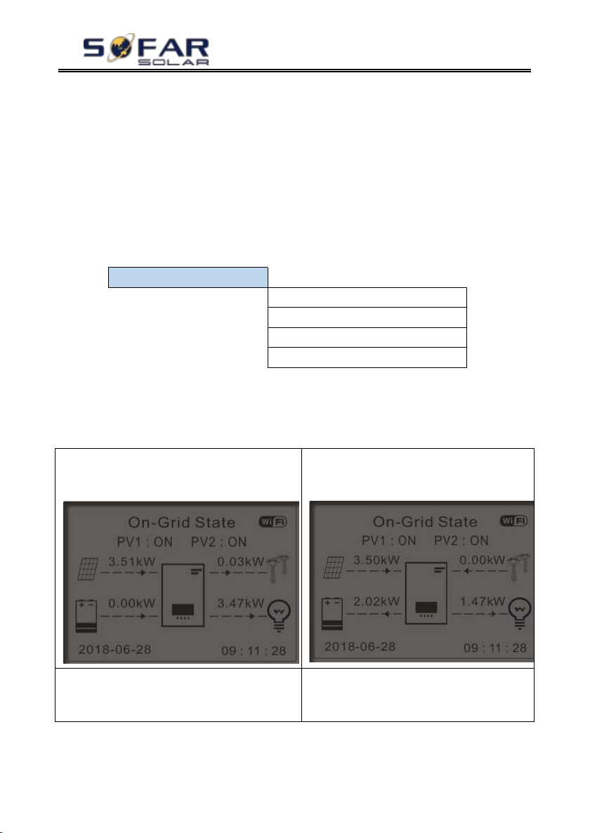
1) If PV generation = LOAD consumption
(ΔP < 100W) HYD-ES won’t charge or
discharge the battery.
2) If PV generation > LOAD
consumption, the surplus power will be
stored in the battery.
3) If the battery is full(or already at Max
Charge Power), excess power will be
exported to the grid.
4) If PV generation < LOAD
consumption, it will discharge the battery
to supply power to load.
language.
2. Set Time
Select “2. Time”, press “ok” to enter time setting interface, system time
format is 20YY-MM-DD HH:MM:SS
Press “up” or “down” to change the 1stdigit, press “ok” to switch to
next digit, after inputting the current time, press “ok”.
3. Energy Storage Mode
Select “3. Energy Storage Mode”, press “ok” to enter energy storage mode
setting interface.
1) Set Self-use Mode
Select “1. Self-use Mode”, then press “ok”.
In Self-use mode, HYD-ES inverter will automatically charge & discharge the
battery.
Copyright © Shenzhen SOFARSOLAR Co., Ltd
Page 36
HYD 3K~6K-ES User manual
- 31 -
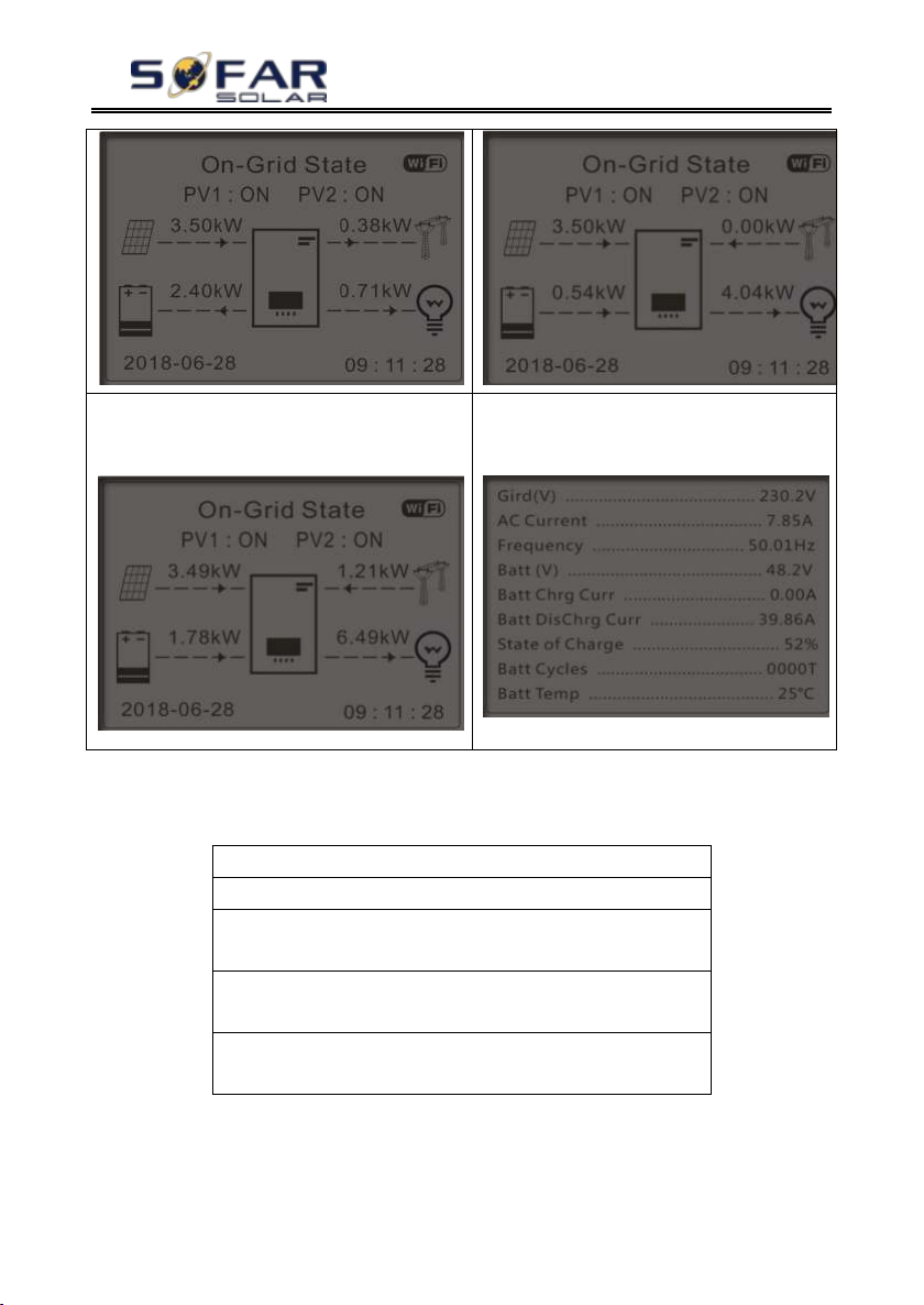
5) If PV generation + Battery < LOAD
consumption, HYD-ES inverter will import
power from the grid.
6) Press “down” button to view current
grid/battery parameters, press “up” to get
back to main interface.
Set Time-of-use Mode
Rules. 0: Enabled
From To SOC Charge
02h00m - 04h00m 070% 1000W
Effective date
Dec. 22 - Mar. 21
Weekday select
Mon. Tue. Wed. Thu. Fri. Sat. Sun.
2) Set Time-of-use Mode
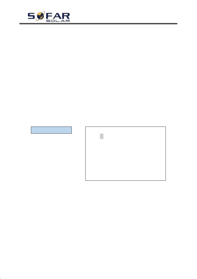
Select“2. Time-of-use Mode”, and then press“ok” to enter Set Time-of-use
mode interface.
If electricity is more expensive in high demand time (peak rate) & electricity is
much cheaper in low demand time (off-peak rate).
You can select an off-peak period to charge your battery. Outside the off-peak
charge period, HYD-ES inverter is working in Auto Mode.
Copyright © Shenzhen SOFARSOLAR Co., Ltd
Page 37
HYD 3K~6K-ES User manual
- 32 -
3.Timing Mode
ok
Timing Mode
Rules. 0:Enabled/Disabled
Charge Start
22 h 00 m
Charge End
05 h 00 m
Charge Power
02000 W
DisCharge Start
14 h 00m
DisCharge End
16 h 00m
DisCharge Power
02500 W
If your family normally go to work/school on weekdays & stay at home on
weekends, which means the home electricity consumption is much higher on
weekends. Thus, you need to store some cheap electricity on weekends only. This is
possible using our Time-of-use mode.
In summer, if your PV system can produce more electricity than your home
electricity consumption. Then you don’t need to set an off-peak charge period to
charge your battery in summer at all. You can select an effective date (normally
winter) for Time-of-use mode in this case. Outside the effective date, HYD-ES
inverter is working in Auto Mode.
You can set multiple Time-of-use rules to meet your more complex
requirement. Right now we support 4 rules maximum (rule 0/1/2/3).
3) Set Timing Mode
Select “3. Timing Mode”, and then press “ok” to enter Set Timing mode
interface. The interface of Set Timing Mode is shown as below. You can select a
charge time/power & discharge time/power in this mode.
Note: normally this mode is used to test whether HYD-ES inverter can
charge & discharge correctly or not. So basically, this mode is used for testing
purposes only.
4) Set Passive Mode
Select “4. Passive Mode”, and then press “ok”.
For more detailed information, please ask representative of SOFAR to get a
copy of passive mode communication protocol.
4. PV Input Mode
PV input mode selection: HYD-ES inverter has 2 MPPT channels. The 2
MPPT can operate independently, also can operate in parallel. If the PV strings are
connected in parallel outside the inverter, you should choose the “in parallel
Copyright © Shenzhen SOFARSOLAR Co., Ltd
Page 38
HYD 3K~6K-ES User manual
- 33 -
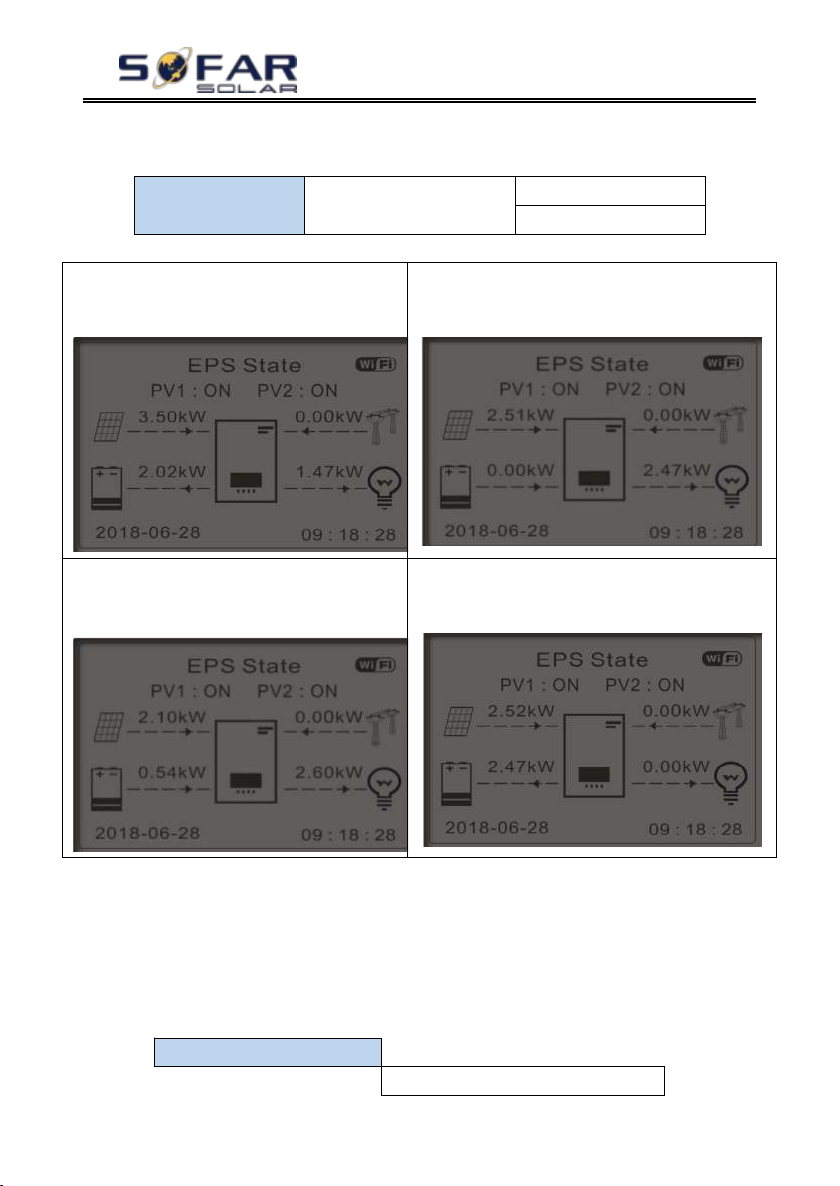
5. Set EPS Mode
1.EPS Mode Control
1.Enable EPS Mode
2.Disable EPS Mode
7.Auto Test
1.Autotest Fast
1) If PV generation > LOAD
consumption (ΔP > 100W), HYD-ES
inverter will charge battery.
2) If PV generation = LOAD consumption,
HYD-ES inverter wont’ charge or discharge
battery.
3) If PV generation < LOAD
consumption (ΔP > 100W), HYD-ES
inverter will discharge battery.
4) If PV generation is normal,but LOAD
consumption=0, the surplus power will be
stored in the battery.
“Up” ↑
“Down”
mode”, otherwise use the default setting (independent mode).
5. EPS Mode
6. Communication Addr.
Select “6. Set Communication Addr.”, press “ok”. Press “up” or “down”
to change the 1st digit, press “ok” to switch to next digit, after changing the
485-communication address (default :01), press “ok”.
7. Auto Test (ONLY for Italian Market)
Select “7. Auto Test”, press “ok” to enter autotest interface.
Copyright © Shenzhen SOFARSOLAR Co., Ltd
Page 39
- 34 -
2.Autotest STD
3.QF Time Setting
4.QV Time Setting
5.Control 81.S1
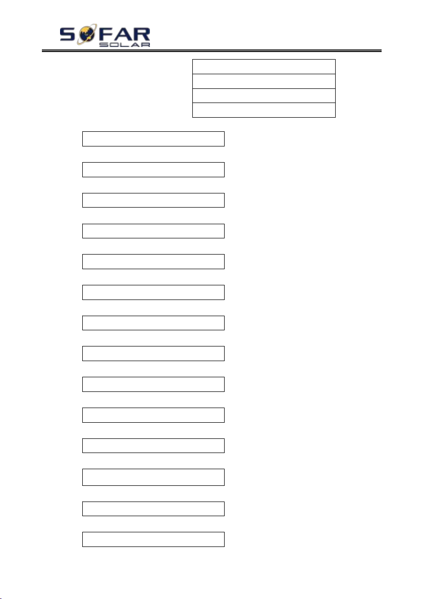
1) Autotest Fast
Start Autotest
↓
Press “ok” to start
Testing 59.S1...
↓
Wait
Test 59.S1 OK!
↓
Wait
Testing 59.S2...
↓
Wait
Test 59.S2 OK!
↓
Wait
Testing 27.S1...
↓
Wait
Test 27.S1 OK!
↓
Wait
Testing 27.S2...
↓
Wait
Test 27.S2 OK!
↓
Wait
Testing 81>S1...
↓
Wait
Test 81>S1 OK!
↓
Wait
Testing 81>S2…
↓
Wait
Test 81>S2 OK!
↓
Wait
Testing 81<S1...
HYD 3K~6K-ES User manual
Copyright © Shenzhen SOFARSOLAR Co., Ltd
Page 40
HYD 3K~6K-ES User manual
- 35 -
↓
Wait
Test 81<S1 OK!
↓
Wait
Testing 81<S2...
↓
Wait
Test 81<S2 OK!
↓
Press “ok”
Auto Test OK!
↓
Press “down”
59.S1 threshold 253V 900ms
↓
Press “down”
59.S1: 228V 902ms
↓
Press “down”
59.S2 threshold 264.5V 200ms
↓
Press “down”
59.S2: 229V 204ms
↓
Press “down”
27.S1 threshold 195.5V 400ms
↓
Press “down”
27.S1: 228V 408ms
↓
Press “down”
27.S2 threshold 92V 200ms
↓
Press “down”
27.S2: 227V 205ms
↓
Press “down”
81>.S1 threshold 50.5Hz 100ms
↓
Press “down”
81>.S1 49.9Hz 103ms
↓
Press “down”
81>.S2 threshold 51.5Hz 100ms
↓
Press “down”
81>.S2 49.9Hz 107ms
Copyright © Shenzhen SOFARSOLAR Co., Ltd
Page 41
HYD 3K~6K-ES User manual
- 36 -
↓
Press “down”
81<.S1 threshold 49.5Hz 100ms
↓
Press “down”
81<.S1 50.0Hz 105ms
↓
Press “down”
81<.S2 threshold 47.5Hz 100ms
↓
Press “down”
81<.S2 50.1Hz 107ms
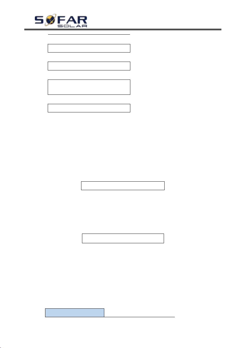
Set: *. *** s
Set:** s
2.Advanced Setting
Input Password 0715
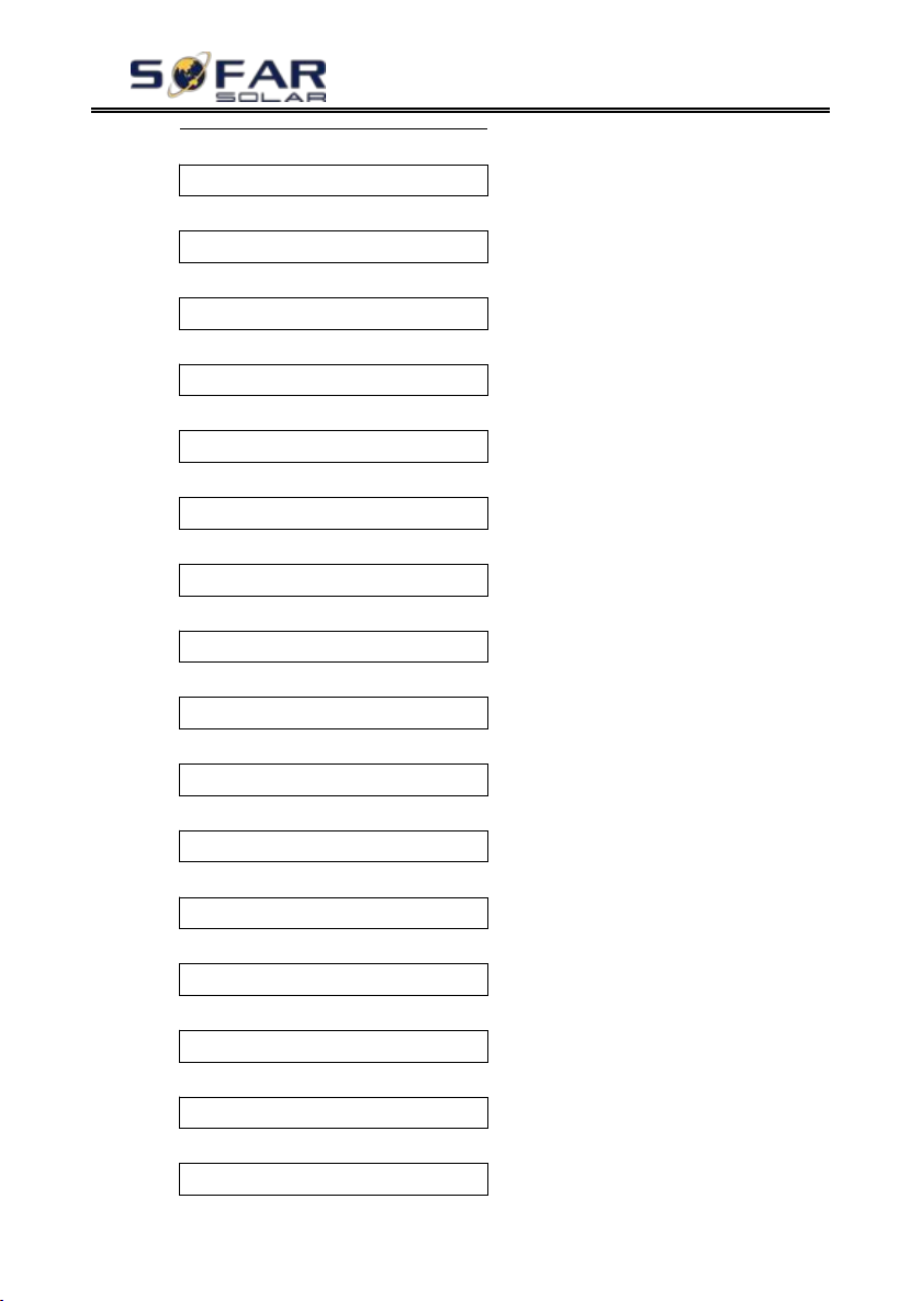
Select “1. Autotest Fast”, then press “ok” to start Auto test Fast.
2) Autotest STD
Select “2. Autotest STD”, then press “ok” to start Auto test STD.
The test procedure is same as Autotest Fast, but it’s much more time
consuming.
3) PF Time Setting
Select “3. PF Time Setting”, then press “ok”. The following will be shown
on the display:
Press “up” or “down” to change the 1st digit, press “ok” to switch to
next digit. After changing all digits, press “ok”.
4) QV Time Setting
Select “4. QV Time Setting”, then press “ok”. The following will be shown
on the display:
Press “up” or “down” to change the 1st digit, press “ok” to switch to
next digit. After changing all digits, press “ok”.
5) Control 81.S1
Select “5. Control 81.S1”, press “ok”. Press “up” or “down” to select
“Enable 81.S1” or “Disable 81.S1”, press “ok”.
6.4.2. Advanced setting
Copyright © Shenzhen SOFARSOLAR Co., Ltd
Page 42
HYD 3K~6K-ES User manual
- 37 -
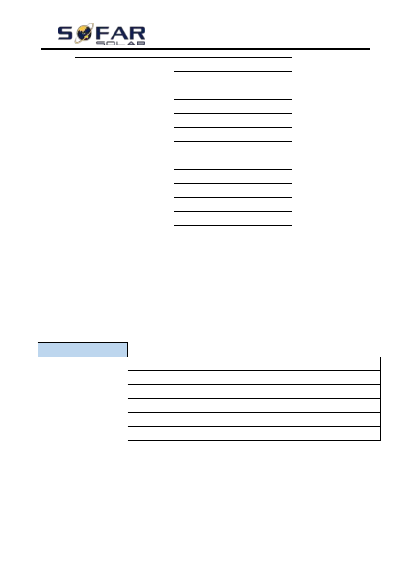
1.Battery Parameter
2.Clear Energy Data
3.Clear Events
4.Country Settings
5.Anti Reflux
6.IV Curve Scan
7.Battery Active
8.Logic interface
9.CT Direction
10.Set Bat Uninterrupted
11.CT Calibration
12.CT Error Detection
1.Battery Parameter
1)Battery Type
7)Max Discharge (A)
2)*Battery Capacity
8)*Low (V) Protection
3)Discharge Depth
9)*Min Discharge (V)
4)Max Charge (A)
10)*Empty Discharged (V)
5)*Over (V) Protection
11)*Full Charged (V)
6)*Max Charge (V)
12)Save
Select “2. Advanced Setting” and press “ok”, “input password” is shown.
Input the password ”0715”, press “up” or “down” to change the 1st digit,
press “ok” to switch to next digit, when “0715” is shown on the screen, press
“ok” to enter “2. Advanced Setting” interface.
If “Incorrect, Try Again!” is shown on the screen, press “back” and input
the password again.
1. Battery Parameter
Note: 2)*, 5)*, 6)*, 8)*, 9)*, 10)* and 11)* settings are only for DEFAULT
battery type.
1) Battery Type
Select “1. Battery Type” and press “ok”. Press “up” or “down” to
select the battery type. Press “ok”.
2) *Battery Capacity (only for DEFAULT battery type)
Select “2. Battery Capacity” and press “ok”. Press “up” or “down” to change
Copyright © Shenzhen SOFARSOLAR Co., Ltd
Page 43

- 38 -
the 1st digit, press “ok” to switch to next digit. Input the value of battery capacity.
Discharge Depth
50%
EPS Discharge Depth
80%
EPS Restore Depth
20%
Press “ok”.
3) Discharge Depth
Select “3. Discharge Depth” and press “ok” to enter discharge depth interface.
Press “up” or “down” to change the 1st digit, press “ok” to switch to
next digit. Input the value of Discharge Depth & EPS Discharge Depth per battery
specification. Press “ok”.
For example: if Discharge Depth = 50% & EPS Discharge Depth = 80%.
While grid is connected: HYD-ES inverter won’t discharge the battery when
its SOC is less than 50%.
In case of blackout: HYD-ES inverter will work in EPS mode (if EPS mode is
enabled) & keep discharging the battery till battery SOC is less than 20%.
4) Max. Charge (A)
Select “4. Max. Charge (A)” and press “ok”. Press “up” or “down”
to change the 1st digit, press “ok” to switch to next digit. Input the value of Max.
Charge (A) per battery specification. Press “ok”.
5) *Over (V) Protection (only for DEFAULT battery type)
Select “5. Over (V) Protection” and press “ok. Press “up” or “down”
to change the 1st digit, press “ok” to switch to next digit. Input the value of Over
(V) Protection per battery specification. Press “ok”.
6) *Max. Charge (V) (only for DEFAULT battery type)
Select “6. Max. Charge (V)” and press “ok”. Press “up” or “down”
to change the 1st digit, press “ok” to switch to next digit. Input the value of Max.
Charge (V) per battery specification. Press “ok”.
7) Max. Discharge (A)
Select “7. Max. Discharge (A)” and press “ok”. Press “up” or “down”
to change the 1st digit, press “ok” to switch to next digit. Input the value of Max.
HYD 3K~6K-ES User manual
Copyright © Shenzhen SOFARSOLAR Co., Ltd
Page 44

HYD 3K~6K-ES User manual
- 39 -
5.Anti Reflux Control
Discharge (A) per battery specification. Press “ok”.
8) *Low (V) Protection (only for DEFAULT battery type)
Select “8. Low (V) Protection” and press “ok”. Press “up” or “down”
to change the 1st digit, press “ok” to switch to next digit. Input the value of Low
(V) Protection per battery specification. Press “ok”.
9) *Min. Discharge (V) (only for DEFAULT battery type)
Select “9. Min. Discharge (V)” and press “ok”. Press “up” or “down”
to change the 1st digit, press “ok” to switch to next digit. Input the value of Min.
Discharge (V) per battery specification. Press “ok”.
10) * Empty Discharged (V) (only for DEFAULT battery type)
Select“10. Empty Discharged (V)”and press“ok”. Press“up”or“down”
to change the 1st digit, press“ok”to switch to next digit. Input the value of Empty
Discharged Voltage per battery specification. Press “ok”.
11) * Full Charged (V) (only for DEFAULT battery type)
Select “11. Full Charged (V)” and press “ok”. Press “up” or “down”
to change the 1st digit, press “ok” to switch to next digit. Input the value of Full
Charged Voltage per battery specification. Press “ok”.
12) Save
Select “12. Save” and press “ok” to complete setting battery parameters.
2. Clear Energy Data
Select “2. Clear Energy” and press “ok”, “input password” is shown.
Input the password “0001”, press “up” or “down” to change the 1st digit,
press “ok” to switch to next digit, when “0001” is shown on the screen, press
“ok”. If“Incorrect, Try Again!”is shown on the screen, press“back”and input
the password again.
3. Clear Events
Select “3. Clear Events”, press “ok” button twice to clear all the events.
4. Country (refer to Set country)
Select “4. Country”, press “ok”, current country setting is shown, input new
country code & press “ok”
5. Anti Reflux
Copyright © Shenzhen SOFARSOLAR Co., Ltd
Page 45
HYD 3K~6K-ES User manual
- 40 -
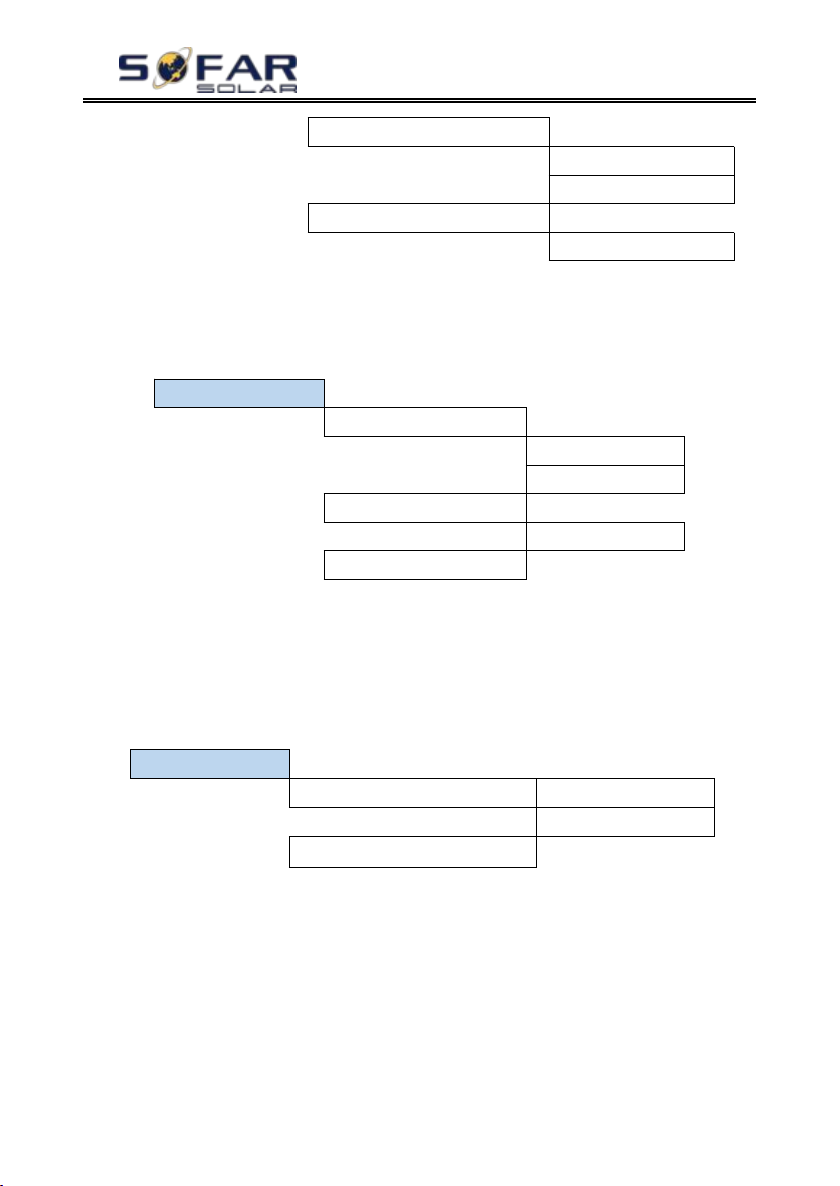
1.Anti Reflux Control
Enable
Disable
2.Reflux Power
***KW
6.IV Curve Scan
1.Scan Control
Enable
Disable
2.Scan Period
***min
3.Force Scan
7.Battery Active
1.Auto Active Control
Enable
Disable
2.Force Active
The user can enable “Anti Reflux Control” to limit the max export power to
grid.
Select “2. Reflux Power” to input desired max export power to grid.
6. IV Curve Scan
The user can enable “IV Curve Scan” (MPPT scan) to make HYD-ES
inverter to find the global max power point periodically to deliver max power from
a partially shaded PV array.
The user can input scan period or make HYD-ES inverter to perform a scan
right away.
7. Battery Active
HYD-ES inverter can activate flat batteries when needed.
The user can enable “Auto Active Control” to allow HYD-ES inverter to
activate flat batteries automatically. Or make HYD-ES inverter to activate the
battery right away.
8. Logic interface control
Select “8. Logic interface Control”, press “ok”, press “up” or “down”
to select “Enable Logic interface” or “Disable Logic interface”, press “ok”.
9. CT Direction
Copyright © Shenzhen SOFARSOLAR Co., Ltd
Page 46

HYD 3K~6K-ES User manual
- 41 -
3.Event List
1.Current Event List
2.History Event List
Select “9.CT Direction”,press“ok” input the interface.
In this interface,press“up”or“down”to select FREEZE or UNFREEZE.If you
select FREEZE,CT directiong will be freezed.When you restart the inverter,CT
direction will stay the same.If you select UNFREEZE,CT directiong won’t be
freezed.When you restart the inverter,CT direction will to be recalibrated again.
10. Set Bat Uninterrupted
It is used for and off - grid quick switching situation, keeps the load power
supply uninterrupted in EPS mode. The use condition is in the spontaneous and
self-use mode, enabling EPS mode, connecting the battery and load, unloading the
load after grid connection, waiting for one minute or longer time, immediately cut
off the power grid when the load is connected, can maintain the load power supply
uninterrupted.
11. CT Calibration
Its function is to calibrate grid-connected power.
Select“11.CT Calibrate”,press“ok” input the actual power minus the difference
of LCD display grid-connected power.
12. CT Error Detection
Select“12.CT Error Detection”,press“ok” input the “CT Error Detection”
enable interface.You can choose to enable or disable the feature.Default to disable.
After enabling the detection function, the machine will report an error after
disconnecting CT for about 1 second. When the machine is connected to the
network (where the CT is) and the PCC power is close to 0kW, no false positives
can be generated. When this function is disabled, no error can be reported even if
the CT is disconnected.
6.4.3. Event List
Event list of HYD-ES inverter, including current event list and history event
list.
1) Current Event List
Select “1. Current Event List”, press “ok” to check the current events.
2) History Event List
Select “2. History Event List”, press “ok” to check the historical events. Press
Copyright © Shenzhen SOFARSOLAR Co., Ltd
Page 47
HYD 3K~6K-ES User manual
- 42 -
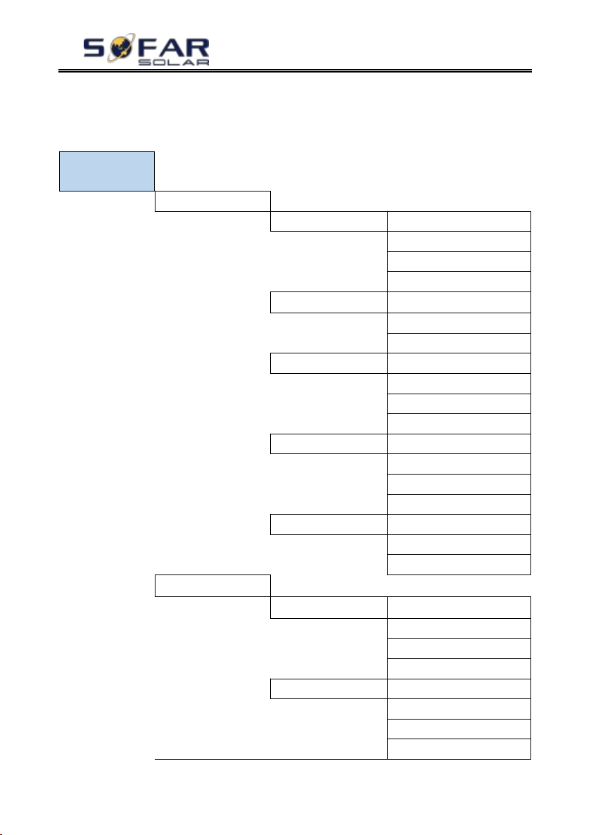
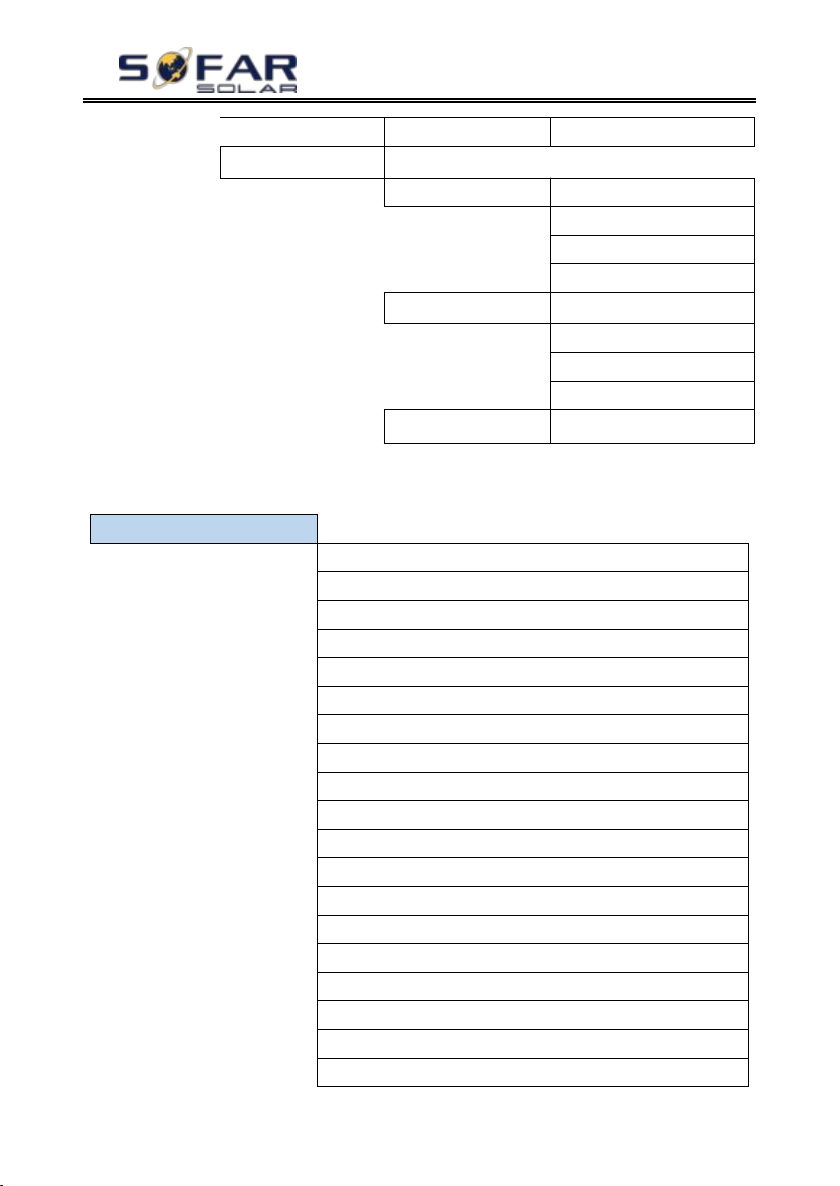
4.System
Information
1.Inverter Info
Inverter Info (1)
Product SN
Software Version
Hardware Version
Power Level
Inverter Info(2)
Country
PV Input Mode
Energy Storage Mode
Inverter Info (3)
RS485 Address
EPS Mode
IV Curve Scan
Anti Reflux
Inverter Info (4)
Logic interface
PF Time Setting
QV Time Setting
Power Factor
Inverter Info (5)
Battery Active
CT Direction
Insulation resistance
2.Battery Info
Battery info (1)
Battery Type
Battery Capacity
Discharge Depth
Max Charge (A)
Battery Info (2)
Over (V) Protection
Max Charge (V)
Max Discharge (A)
Min Discharge (V)
“up” or “down” to check all historical events if there’re more than 1 page of events.
6.4.4. System information interface
Copyright © Shenzhen SOFARSOLAR Co., Ltd
Page 48
- 43 -
Battery Info (3)
EPS Safety Buffer
3.Safety Param.
Safety Param.(1)
OVP 1
OVP 2
UVP 1
UVP 2
Safety Param.(2)
OFP 1
OFP 2
UFP 1
UFP 2
Safety Param.(3)
OVP 10mins
6.4.5. Energy Statistic
5.Energy Statistic
Today
PV ***KWH
Load ***KWH
Export ***KWH
Import ***KWH
Charge ***KWH
Discharge ***KWH
Week
PV ***KWH
Load ***KWH
Export ***KWH
Import ***KWH
Charge ***KWH
Discharge ***KWH
Month
PV ***KWH
Load ***KWH
Export ***KWH
Import ***KWH
HYD 3K~6K-ES User manual
Copyright © Shenzhen SOFARSOLAR Co., Ltd
Page 49
HYD 3K~6K-ES User manual
- 44 -
Charge ***KWH
Discharge ***KWH
Year
PV ***KWH
Load ***KWH
Export ***KWH
Import ***KWH
Charge ***KWH
Discharge ***KWH
Lifetime
PV ***KWH
Load ***KWH
Export ***KWH
Import ***KWH
Charge ***KWH
Discharge ***KWH
Select “5. Energy Statistic”, press “ok” to enter Energy Statistic interface,
it shows the energy generation and consumption within a certain range of time.
Press “up” or “down” to check the daily / weekly / monthly / yearly / lifetime
energy statistics.
6.4.6. Software upgrade
Copy the firmware folder to the root directory of SD card.
Select “6. Software Update”, press “ok”, “input password” is shown. Input the
password (”0715”), press “up” or “down” to change the 1st digit, press “ok” to
switch to next digit, when “0715” is shown on the screen, press “ok”. HYD-ES
inverter will start to upgrade the software automatically.
Detailed Firmware Upgrade Procedure:
Step 1 Turn OFF AC circuit breaker (grid & load), then turn OFF DC isolator
(battery) and PV switch, then remove communication waterproof cover. If
communication cables (CAN/RS485/NTC/CT) have been connected, loosen their
cable glands before removing cover.
Copyright © Shenzhen SOFARSOLAR Co., Ltd
Page 50
HYD 3K~6K-ES User manual
- 45 -
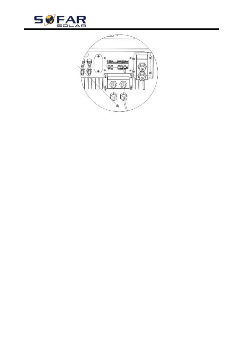
SD card
Step 2 Press the SD card and take it out. Insert the SD card into a micro-SD
card reader, then insert micro-SD card reader into a PC; (NOTE: micro-SD card
reader & PC are not provided by SOFARSOLAR).
Step 3 Format the SD card. Copy the “firmware” folder to the SD card.
Step 4 Insert the SD card back to the SD card slot.
Step 5 Turn ON AC circuit breaker (grid), press “back” to enter main menu.
Press “down” to select “6. Software Update”, then press “ok”.
Step 6 “Input password” is shown. Input the password (“0715”), press “up” or
“down” to change the 1stdigit, press “ok” to switch to next digit, when “0715” is
shown on the screen, press “ok” to start firmware update.
Step 7 After finishing firmware upgrade, turn OFF AC circuit breaker (grid),
lock the communication waterproof cover with four screws, then turn ON AC
circuit breaker (grid), turn ON DC isolator (battery), turn on PV switch, HYD-ES
inverter will start to operate automatically.
NOTE: If “DSP communicate fail”, “Update DSP1 Fail” or “Update DSP2
Fail” is shown on the screen, which means the firmware upgrade is unsuccessful,
please turn OFF AC circuit breaker (grid), wait 5 minutes, then start again from
“Step 5”
Copyright © Shenzhen SOFARSOLAR Co., Ltd
Page 51
HYD 3K~6K-ES User manual
- 46 -
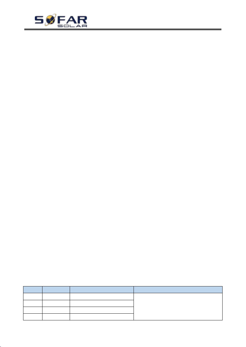
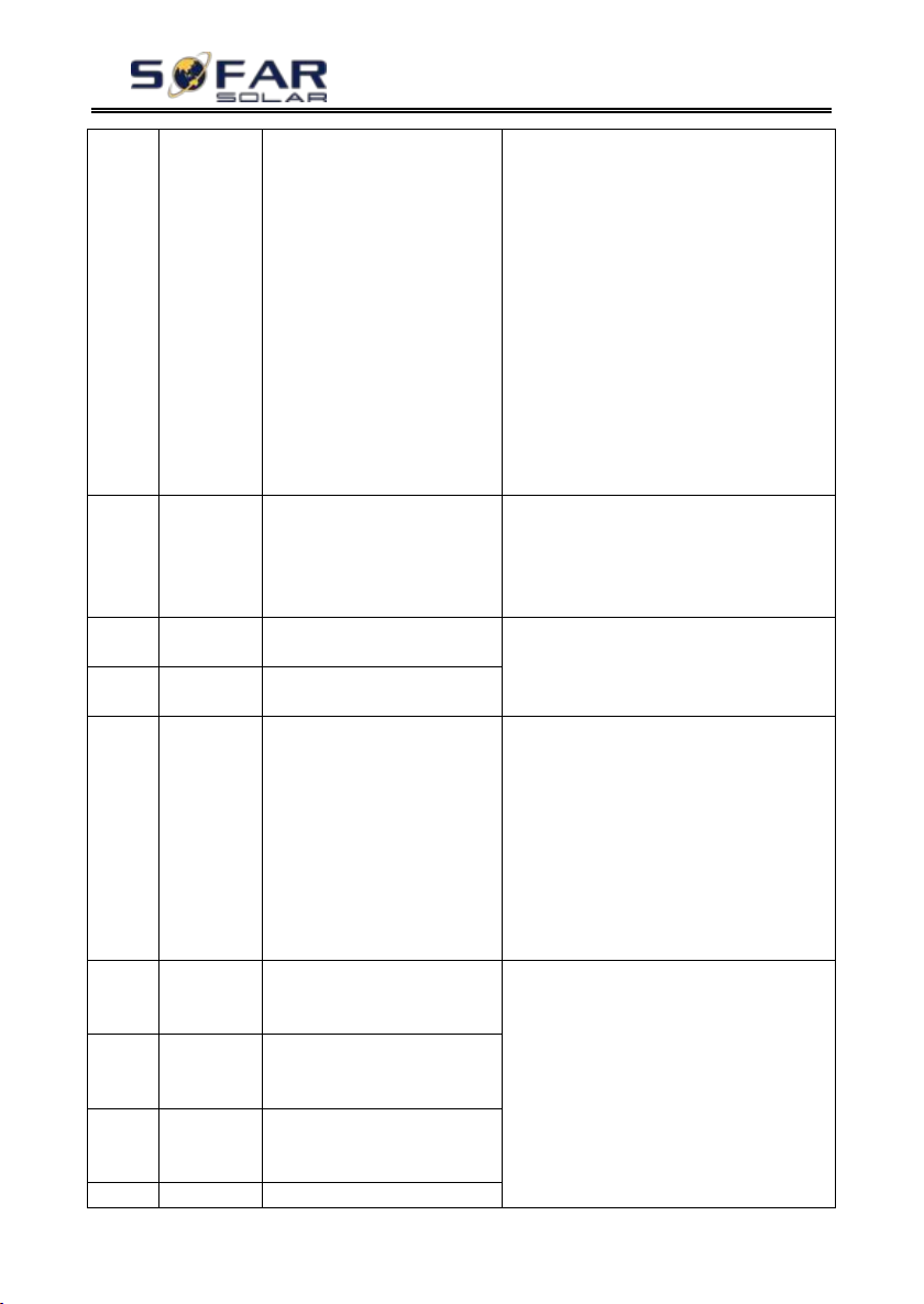
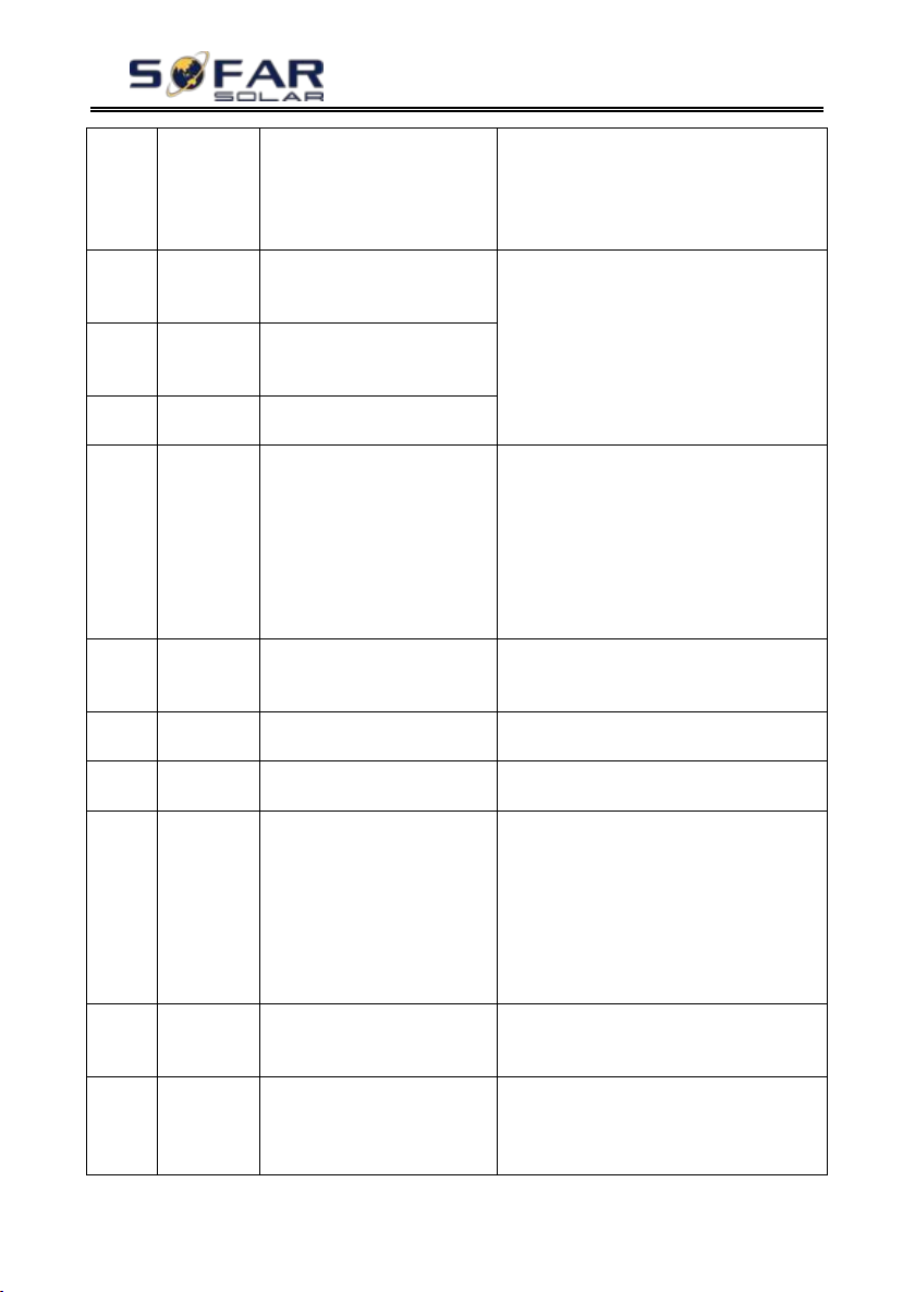
Code
Name
Description
Solution
ID01
GridOVP
The grid voltage is too high
If the alarm occurs occasionally, the
possible cause is that the electric grid is
abnormal occasionally. HYD-ES inverter
will automatically return to normal
ID02
GridUVP
The grid voltage is too low
ID03
GridOFP
The grid frequency is too high
ID04
GridUFP
The grid frequency is too low
7. Troubleshooting
This section contains information and procedures for solving possible
problems with the inverter.
This section help users to identify the inverter fault. Please read the
following procedures carefully:
Check the warning, fault messages or fault codes shown on the
inverter screen, record all the fault information.
If there is no fault information shown on the screen, check whether
the following requirements are met:
- Is the inverter mounted in a clean, dry place with good ventilation?
- Is the DC switch turned ON?
- Are the cables adequately sized and short enough?
- Are the input and output connections and wiring in good condition?
- Are the configuration settings correct for the particular installation?
- Are the display panel and the communication cables properly connected and
undamaged?
Follow the steps below to view recorded problems: Press "back" to
enter the main menu in the normal interface. In the interface screen select
"Event List", then press "ok" to enter events.
Earth Fault Alarm
This inverter complies with IEC 62109-2 clause 13.9 for earth fault alarm
monitoring.
If an Earth Fault Alarm occurs, the fault will be displayed on the LCD
screen,the red light will be on,and the fault can be found in the history of the
fault. For the machine installed with WiFi/GPRS, the alarm information can be
seen on the corresponding monitoring website, and can also be received by the
APP on the mobile phone.
EventList information
Table 7-1 Eventlist
Copyright © Shenzhen SOFARSOLAR Co., Ltd
Page 52
HYD 3K~6K-ES User manual
- 47 -
operating status when the electric grid’s
back to normal.
If the alarm occurs frequently, check
whether the grid voltage/frequency is
within the acceptable range. If yes, please
check the AC circuit breaker and AC wiring
of the HYD-ES inverter.
If the grid voltage/frequency is NOT within
the acceptable range and AC wiring is
correct, but the alarm occurs repeatedly,
contact SOFAR technical support to change
the grid over-voltage, under-voltage,
over-frequency, under-frequency protection
points after obtaining approval from the
local electrical grid operator.
ID05
BatOVP
The battery voltage is too high
If the alarm occurs occasionally, wait a
while to see if the problem is solved.
If the alarm occurs frequently, check
whether the battery overvoltage setting is
inconsistent with the battery specification.
ID06
OVRT
fault
OVRT function is faulty
Check whether the grid voltage fluctuates
greatly.
ID07
LVRT
fault
LVRT function is faulty
ID08
PVOVP
The PV voltage is too high
Check whether too many PV modules are
series connected in a PV string, thus the PV
string voltage (Voc) is higher than the
maximum input voltage of HYD-ES
inverter. If yes, adjust the number of series
connected PV modules to decrease the PV
string voltage to fit the input voltage range
of HYD-ES inverter. HYD-ES inverter will
automatically return to normal status after
correcting adjustments
ID09
HW_LLC
Bus_OVP
LLCBus voltage is too high
and has triggered hardware
protection
ID09- ID12 are internal faults of HYD-ES
inverter, switch OFF HYD-ES inverter,
wait for 5 minutes, then switch ON
HYD-ES inverter. Check whether the
problem is solved.
If no, please contact SOFAR technical
support.
ID10
HW_Boos
t_OVP
Boost voltage is too high and
has triggered hardware
protection
ID11
HwBuckB
oostOCP
BuckBoost current is too high
and has triggered hardware
protection
ID12
HwBatOC
The battery current is too high
Copyright © Shenzhen SOFARSOLAR Co., Ltd
Page 53
HYD 3K~6K-ES User manual
- 48 -
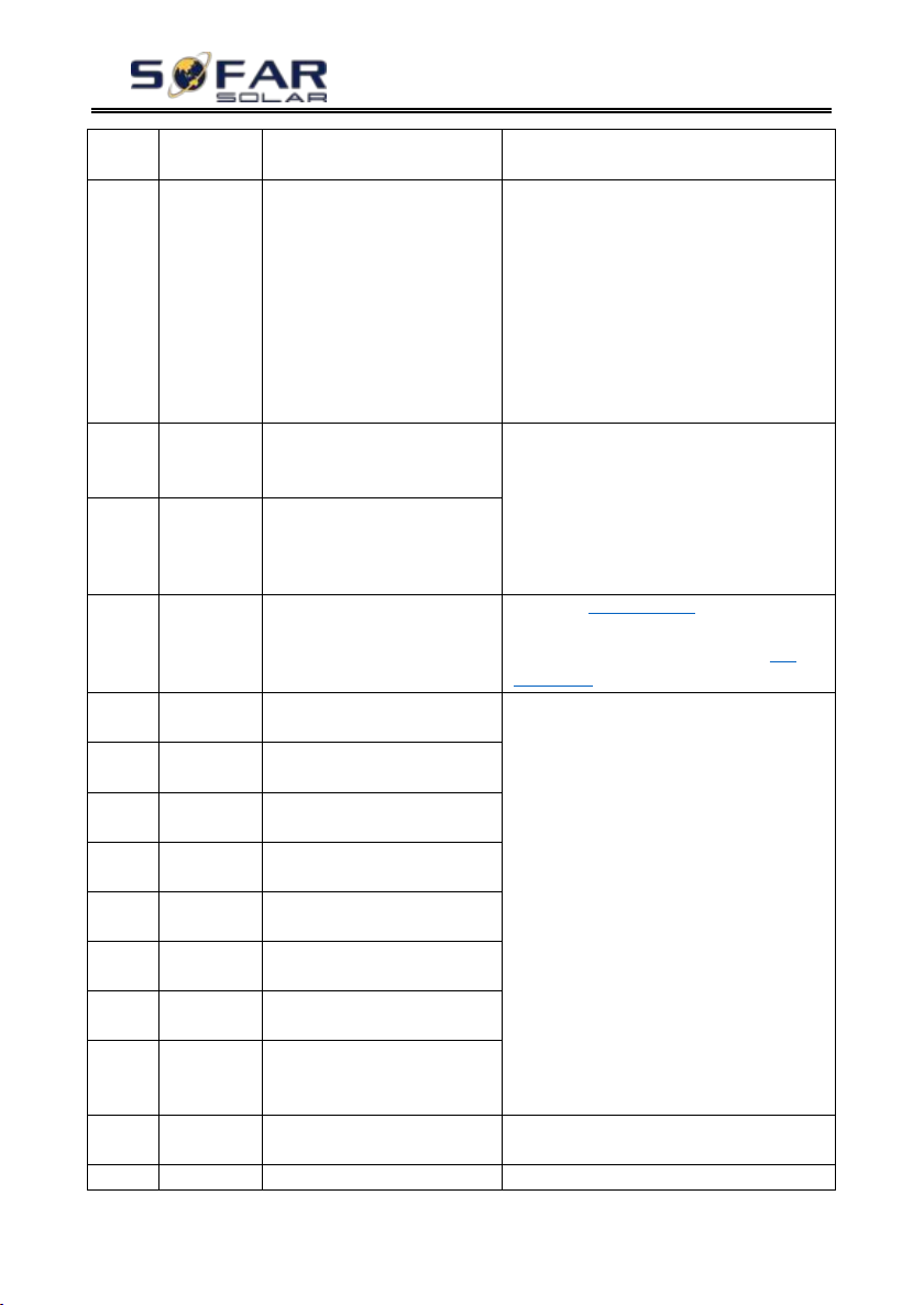
P
and has triggered hardware
protection
ID13
GFCI OCP
The GFCI sampling value
between the master DSP and
slave DSP is not consistent
If the fault occurs occasionally, the possible
cause is that the external circuits are
abnormal occasionally. HYD-ES inverter
automatically returns to normal operating
status after the fault is rectified.
If the fault occurs frequently and lasts a
long time, check whether the insulation
resistance between the PV array and
earth(ground) is too low, also check the
insulation conditions of PV cables.
ID14
HWPVOC
P
The PV current is too high
and has triggered hardware
protection
ID14-ID15 are internal faults of HYD-ES
inverter, switch OFF HYD-ES inverter,
wait for 5 minutes, then switch ON
HYD-ES inverter. Check whether the
problem is solved.
If no, please contact SOFAR technical
support.
ID15
HwAcOC
P
The grid current is too high
and has triggered hardware
protection
ID16
IpvUnbala
nce
Input current is not balanced
Check the PV input mode (parallel mode/
independent mode) setting of HYD-ES
inverter. If it’s incorrect, change the
PV
input mode.
ID17
HwADFau
ltIGrid
The grid current sampling
error
ID17-ID26 are internal faults of HYD-ES
inverter, switch OFF HYD-ES inverter,
wait for 5 minutes, then switch ON
HYD-ES inverter. Check whether the
problem is solved.
If no, please contact SOFAR technical
support.
ID18
HwADFau
ltDCI
The DCI sampling error
ID19
HwADFau
ltVGrid
The grid voltage sampling
error
ID20
GFCIDevi
ceFault
The GFCI sampling error
ID21
MChip_Fa
ult
The master chip fault
ID22
HwAuxPo
werFault
The auxiliary voltage error
ID25
LLCBusO
VP
LLCBus voltage is too high
ID26
SwBusOV
P
Bus voltage is too high and
has triggered software
protection
ID27
BatOCP
Battery current is too high
If the fault occurs frequently, please contact
SOFAR technical support.
ID28
DciOCP
The DCI is too high
ID28-ID31 are internal faults of HYD-ES
Copyright © Shenzhen SOFARSOLAR Co., Ltd
Page 54
HYD 3K~6K-ES User manual
- 49 -
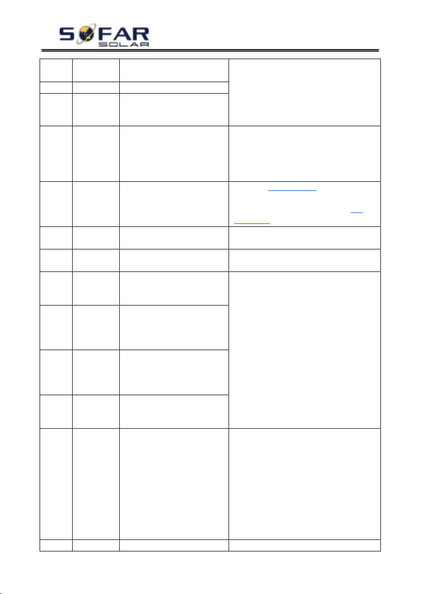
inverter, switch OFF HYD-ES inverter,
wait for 5 minutes, then switch ON
HYD-ES inverter. Check whether the
problem is solved.
If no, please contact SOFAR technical
support.
ID29
SwOCPIns
tant
The grid current is too high
ID30
BuckOCP
Buck current is too high
ID31
AcRmsOC
P
The output current is too high
ID32
SwBOCPI
nstant
The input current is too high
Check whether the input current is higher
than the maximum input current of
HYD-ES inverter, then check the input
wiring, if both are correct, please contact
technical support.
ID33
PvConfigS
etWrong
Incorrect input mode
Check the PV input mode (parallel mode/
independent mode) setting of HYD-ES
inverter. If it’s incorrect, change the
PV
input mode.
ID34
Overload
The load is overloaded
Check if the load power is out of range, and
if so, adjust the power to the correct range.
ID35
CT Fault
The CT is fault
Check whether the CT connection is firm
and the installation direction is correct.
ID48
Consisten
Fault
The GFCI sampling value
between the master DSP and
slave DSP is not consistent
ID48-ID51 are internal faults of HYD-ES
inverter, switch OFF HYD-ES inverter,
wait for 5 minutes, then switch ON
HYD-ES inverter. Check whether the
problem is solved.
If no, please contact SOFAR technical
support.
ID49
Consistent
Fault_Vgri
d
The grid voltage sampling
value between the master DSP
and slave DSP is not
consistent
ID50
Consistent
Fault_Fgri
d
The grid frequency sampling
value between the master DSP
and slave DSP is not
consistent
ID51
Consistent
Fault_DCI
The Dci sampling value
between the master DSP and
slave DSP is not consistent
ID52
BatComm
unicaton
Flag
HYD-ES inverter can’t
communicate with Lithium
battery BMS correctly.
Make sure the battery you’re using is
compatible with HYD-ES inverter.
Make sure you’ve selected the correct
battery type. Check the communication
cable between battery & HYD-ES inverter.
It’s recommended to use CAN
communication.
For PYLONTECH US2000 PLUS battery,
and you’re using RS485 communication,
the ADD DIP switch should be all down.
ID53
SpiComm
SPI communication is fault
ID53-ID55 are internal faults of HYD-ES
Copyright © Shenzhen SOFARSOLAR Co., Ltd
Page 55
HYD 3K~6K-ES User manual
- 50 -
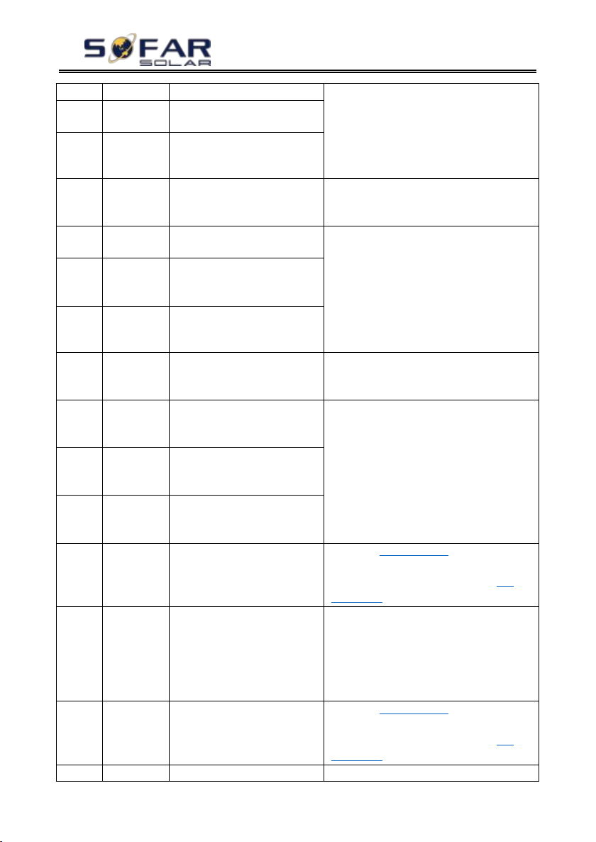
Lose
inverter, switch OFF HYD-ES inverter,
wait for 5 minutes, then switch ON
HYD-ES inverter. Check whether the
problem is solved.
If no, please contact SOFAR technical
support.
ID54
SciComm
Lose
SCI communication is fault
ID55
RecoverRe
layFail
The relays fault
ID56
PvIsoFault
The insulation resistance is
too low
Check the insulation resistance between the
PV array and earth(ground), if a short
circuit occurs, rectify the fault.
ID57
OverTemp
Fault_BAT
The battery temp is too high
Please make sure HYD-ES inverter is
installed in a place without direct sunlight.
Please make sure HYD-ES inverter is
installed in a cool / well-ventilated place.
Make sure the inverter is vertically installed
& the ambient temperature is less than the
temperature upper limit of HYD-ES
inverter
ID58
OverTemp
Fault_
HeatSink
The temperature of heat sink
is too high
ID59
OverTemp
Fault_Env
The environment temperature
is too high
ID60
PE
connectFa
ult
Grounding not correct
Check the grounding of AC output PE wire.
ID65
unrecover
HwAcOC
P
The grid current is too high
and has cause unrecoverable
hardware fault
ID65-ID67 are internal faults of HYD-ES
inverter, switch OFF HYD-ES inverter,
wait for 5 minutes, then switch ON
HYD-ES inverter. Check whether the
problem is solved.
If no, please contact SOFAR technical
support.
ID66
unrecover
BusOVP
The bus voltage is too high
and has cause unrecoverable
fault
ID67
BitEPSunr
ecover
BatOcP
Unrecoverable fault of battery
overcurrent in EPS mode
ID68
Unrecover
Ipv
Unbalance
The input current is
unbalance, and has triggered
unrecoverable fault
Check the PV input mode (parallel mode/
independent mode) setting of HYD-ES
inverter. If it’s incorrect, change the
PV
input mode.
ID70
Unrecover
OCPInstan
t
The grid current is too high,
and has cause unrecoverable
fault
Internal faults of HYD-ES inverter, switch
OFF HYD-ES inverter, wait for 5 minutes,
then switch ON HYD-ES inverter. Check
whether the problem is solved.
If no, please contact SOFAR technical
support.
ID73
Unrecover
IPVConfig
SetWrong
Input mode is uncorrectly
set
Check the PV input mode (parallel mode/
independent mode) setting of HYD-ES
inverter. If it’s incorrect, change the PV
input mode.
ID74
Unrecover
Input current is too high this
Internal faults of HYD-ES inverter, switch
Copyright © Shenzhen SOFARSOLAR Co., Ltd
Page 56
HYD 3K~6K-ES User manual
- 51 -
PvInatant
caused unrecoverable
hardware fault
OFF HYD-ES inverter, wait for 5 minutes,
then switch ON HYD-ES inverter. Check
whether the problem is solved.
If no, please contact SOFAR technical
support.
ID75
Unrecover
WRITE
EEPROM
Unrecoverable EEPROM
write
ID75-ID77 are internal faults of HYD-ES
inverter, switch OFF HYD-ES inverter,
wait for 5 minutes, then switch ON
HYD-ES inverter. Check whether the
problem is solved.
If no, please contact SOFAR technical
support.
ID76
Unrecover
REDEEPR
OM
Unrecoverable EEPROM read
ID77
Unrecover
RelayFail
Relay has triggered permanent
fault
ID81
Over
TempDerat
ing
Internal temperature is too
high.
Please make sure HYD-ES inverter is
installed in a place without direct sunlight.
Please make sure HYD-ES inverter is
installed in a cool / well-ventilated place.
Make sure the inverter is vertically installed
& the ambient temperature is less than the
temperature upper limit of HYD-ES
inverter.
ID82
Over
FreqDerati
ng
AC frequency is too high
Please make sure the grid frequency is
within the acceptable range.
ID83
RemoteDe
rating
Remote power derate
HYD-ES inverter receives a remote signal
to decrease its power.
ID84
Remote
Off
Switch OFF HYD series
inverter remotely
HYD-ES inverter receives a remote signal
to switch OFF.
ID85
SOC <= 1
-DOD or
Battery
undervolta
ge
Battery voltage below SOC
For example, if you set DOD to 30%, when
SOC is less than 70%, you will see ID85 in
the event list. HYD-ES inverter won’t
discharge the battery when ID85 is present.
Or this is an indication of low battery
voltage. HYD-ES inverter won’t discharge
battery in this case to ensure long battery
cycle life.
ID86
Force
charge
failure
Force charge failure
Check whether PV and grid conditions
meet charging conditions.
ID94
Software
version is
not
consistent
Software version between
control board and com board
is not consistent
Contact SOFAR technical support to
upgrade software.
Copyright © Shenzhen SOFARSOLAR Co., Ltd
Page 57
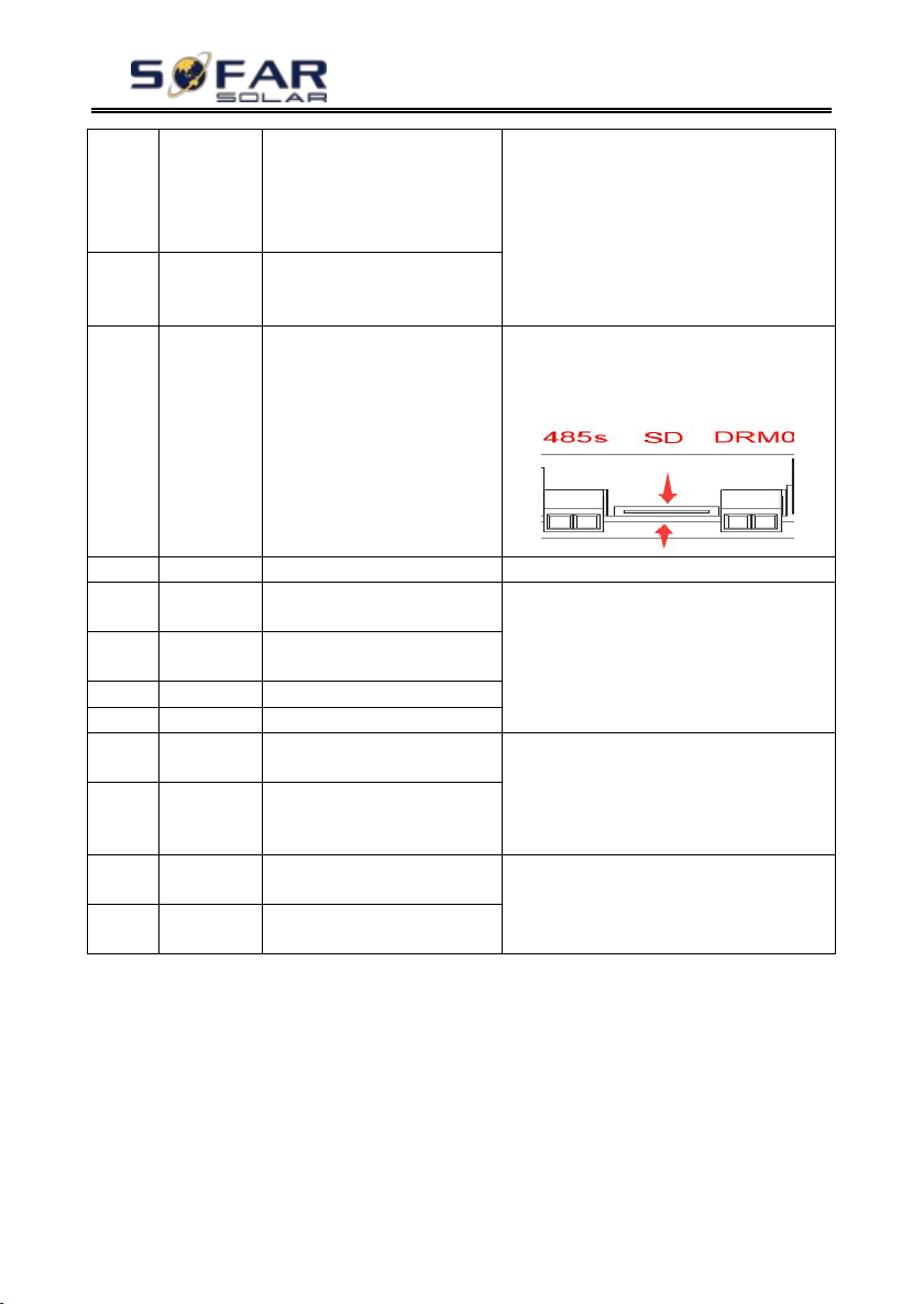
HYD 3K~6K-ES User manual
- 52 -
ID95
Communic
ation
board
EEPROM
Fault
The Communication board
EEPROM is faulty
ID95-ID96 are internal faults of HYD-ES
inverter, switch OFF HYD-ES inverter,
wait for 5 minutes, then switch ON
HYD-ES inverter. Check whether the
problem is solved.
If no, please contact SOFAR technical
support.
ID96
RTC clock
chip
anomaly
RTC clock chip is faulty
ID98
SDfault
The SD card is faulty
Normally ID98 is caused by loose SD card
holder. Click & take out SD card, press SD
card holder then insert SD card back can
normally solve this problem.
ID99
Wifi fault
The Wifi is error
Just for alarm in factory.
ID100
BatOCD
Battery over current
discharging protect
ID100-ID103 is battery fault. If this fault
occurs occasionally, wait a few minutes to
see whether the problem is solved.
If this fault occurs frequently, please
contact SOFAR technical support.
ID101
BatSCD
Discharging short circuit
protect
ID102
BatOVP
Battery Overvoltage protect
ID103
BatUV
Battery low voltage protect
ID104
BatOTD
Battery high temperature
protect while discharging
Make sure battery is in a well-ventilated
place.
Try to decrease the max discharge (A)
or/and max charge (A) to see if the problem
is solved.
ID105
BatOTC
Battery high temperature
protect while charging
ID106
BatUTD
Battery low temperature
protect while discharging
Try to increase the ambient temperature of
the battery.
ID107
BatUTC
Battery low temperature
protect while charging
Maintenance
Inverters generally do not need any daily or routine maintenance. Heat sink
should not be blocked by dust, dirt or any other items. Before the cleaning, make
sure that the DC SWITCH is turned OFF and the circuit breaker between inverter
and electrical grid is turned OFF. Wait at least for 5 minutes before the Cleaning.
Inverter cleaning
Please clean the inverter with an air blower, a dry & soft cloth or a soft bristle
brush. Do NOT clean the inverter with water, corrosive chemicals, detergent, etc.
Copyright © Shenzhen SOFARSOLAR Co., Ltd
Page 58

HYD 3K~6K-ES User manual
- 53 -
Heat sink cleaning
For the long-term proper operation of inverters, ensure there is enough space
around the heat sink for ventilation, check the heat sink for blockage (dust, snow,
etc.) and clean them if they exist. Please clean the heat sink with an air blower, a
dry & soft cloth or a soft bristle brush. Do NOT clean the heat sink with water,
corrosive chemicals, detergent, etc.
Copyright © Shenzhen SOFARSOLAR Co., Ltd
Page 59
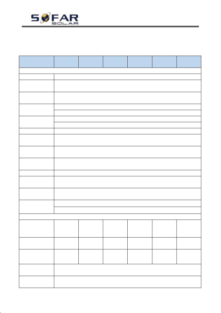
HYD 3K~6K-ES User manual
- 54 -
Model
HYD
3000-ES
HYD
3600-ES
HYD
4000-ES
*HYD
4600-ES
HYD
5000-ES
HYD
6000-ES
Battery Parameters
Battery Type
Lead-acid, Lithium-ion
Nominal battery
voltage
48V
Battery voltage
range
42 - 58V
Min discharge
voltage
Lithium:(according to BMS), General 46.0V
Lead acid: 44.0V
Max charge
voltage
Lithium-ion:(according to BMS), Max 58V
Lead acid: 58V
Battery capacity
50-2000Ah
Recommended
storage capacity
9.6 kWh
Max charge
current
65A
Charge current
range
0 – 65A programmable
Charge curve
3 - stage adaptive with maintenance
Max discharge
current
70A programmable
Battery
protection
Over voltage protection / Over current protection / Over temperature
protection
Depth of
discharge
Lithium: 0 – 90% DOD adjustable
Lead acid: 0 – 50% DOD adjustable
PV parameters
Recommended
Max.PV input
power
3990Wp
4790Wp
5320Wp
6120Wp
6650Wp
7980Wp
Max DC input
power
3500W
4000W
4400W
5000W
5500W
6600W
Max DC power
for single MPPT
2000W
(160-520V)
2400W
(180-520V)
2600W
(200-520V)
2800W
(230-520V)
3000W
(250-520V)
3500W
(300-520V)
The max DC
input voltage
600V
Start-up DC
voltage
120V
8. Technical Data
Copyright © Shenzhen SOFARSOLAR Co., Ltd
Page 60
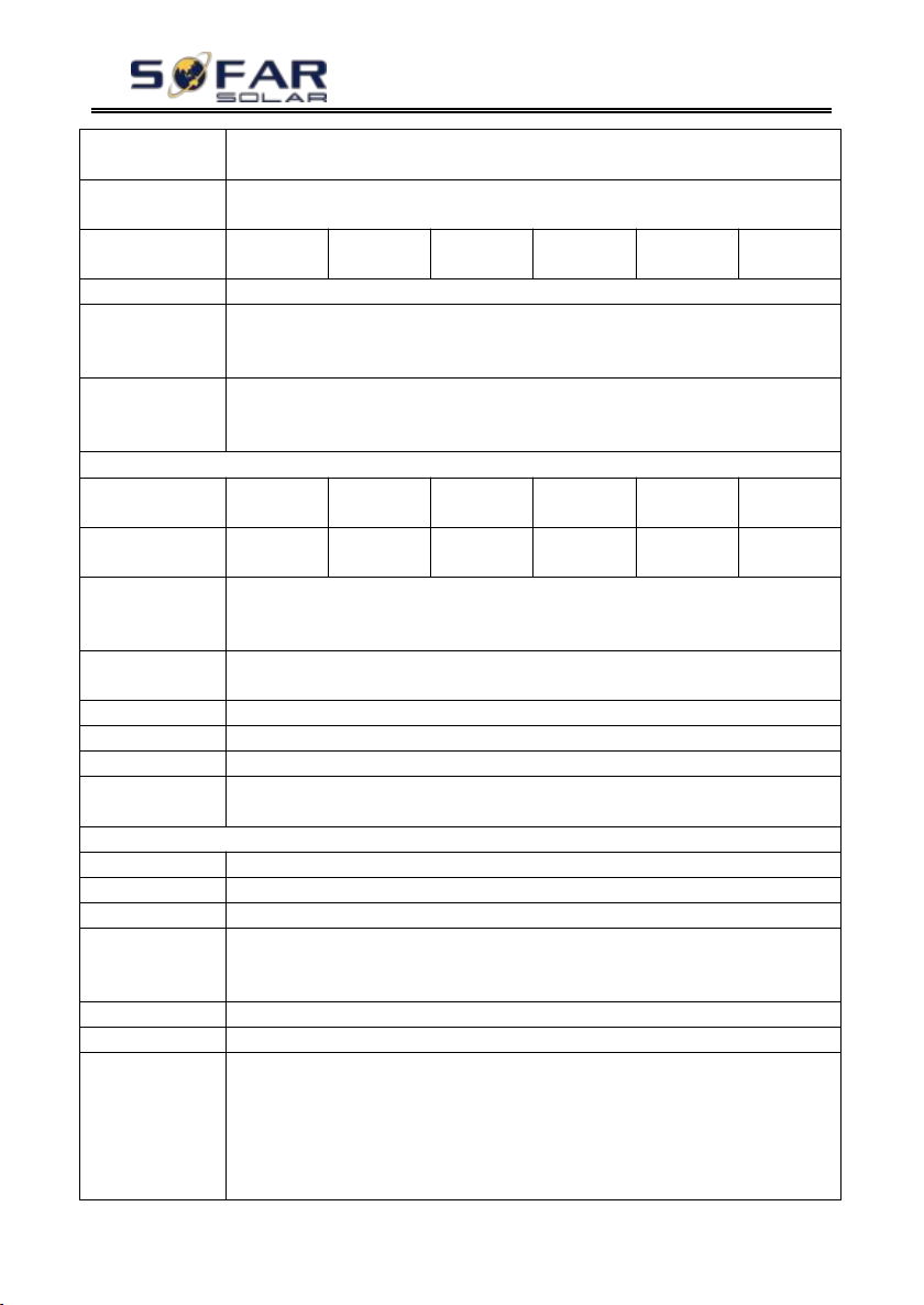
HYD 3K~6K-ES User manual
- 55 -
Nominal DC
Voltage
360V
MPPT operating
voltage range
90-580V
Full load DC
voltage range
160-520V
180-520V
200-520V
230-520V
250-520V
300-520V
MPPT number
2
The max DC
input current
12A/12A
The max DC
input short
current
15A/15A
AC parameters
Max output
power
3000W
3680W
4000W
4600W
5000W
6000W
Max output
current
13.7A
16A
18.2A
21.0A
22.8A
27.3A
Nominal grid
voltage &
frequency
220V,230V,240V,
44 – 55Hz or 54 – 66Hz
AC voltage
range
180 – 276V (according to local authority requirements)
THD
<3%
Power factor
1default (+ / - 0.8 adjustable)
Inrush current
0.8A / 1us
Max output fault
current
100A / 1us
System parameters
Max efficiency
Charge: 94.6% / discharge 94.6%
Standby losses
< 10W (PV SPS)
Topology
High frequency isolation(for bat)
Ingress
protection
ratings
IP 65
Safety protection
Anti-islanding, RCMU, ground fault monitoring
Communication
Wi-Fi/GPRS/Ethernet(optional), RS485, SD,CAN2.0
Certification
EN 61000-6-2, EN 61000-6-3, EN 61000-3-2, EN 61000-3-3, EN 61000-3-11, EN
61000-3-12
IEC62109-1/2, IEC62040-1, IEC62116, IEC61727, IEC-61683,
IEC60068(1,2,14,30)
AS/NZS 4777, VDE V 0124-100, V 0126-1-1, VDE-AR-N 4105, CEI 0-21,
EN50438/EN50549, G83/G59/G98/G99, UTE C15-712-1, UNE 206 007-1
Copyright © Shenzhen SOFARSOLAR Co., Ltd
Page 61
HYD 3K~6K-ES User manual
- 56 -
Environmental data
Ambient
temperature
range
-25℃ to +60℃(Derating above +45℃)
Relative
humidity range
0% - 100% (no condensing)
Protective class
Class I
Max operating
altitude
2000m
Current
transformer
connection
Hard wired
General data
Noise
<25dB
Weight
20.5kg
Cooling
Natural convection
Dimensions
(W*H*D)
566 x 394 x 173 mm
Display
LCD display
Warranty
5 years or more
EPS (Emergency Power Supply) data
EPS rated power
3000VA
EPS nominal v
oltage/frequency
230V, 50/60Hz
EPS rated
current
13.2A
THD
<3%
Switch time
10mS default
The models marked with“ *” should be available only for some designated
countries.
Copyright © Shenzhen SOFARSOLAR Co., Ltd
Page 62

HYD 3K~6K-ES User manual
- 57 -
9. Quality Assurance
Standard warranty period
The standard warranty period of inverter is 60 months (5 years). There are two
calculation methods for the warranty period:
1. Purchase invoice provided by the customer: the first flight provides a
standard warranty period of 60 months (5 years) from the invoice date;
2. The customer fails to provide the invoice: from the production date
(according to the SN number of the machine), Our company provides a warranty
period of 63 months (5.25 years).
3. In case of any special warranty agreement, the purchase agreement shall
prevail.
Extended warranty period
Within 12 months of the purchase of the inverter (based on the purchase
invoice) or within 24 months of the production of the inverter(SN number of
machine, based on the first date of arrival),Customers can apply to buy extended
warranty products from the company's sales team by providing the product serial
number, Our company may refuse to do not conform to the time limit extended
warranty purchase application. Customers can buy an extended warranty of 5, 10,
15 years.
If the customer wants to apply for the extended warranty service, please
contact the sales team of our company. to purchase the products that are beyond the
purchase period of extended warranty but have not yet passed the standard quality
warranty period. Customers shall bear different extended premium.
During the extended warranty period, pv components GPRS, WIFI and
lightning protection devices are not included in the extended warranty period. If
they fail during the extended warranty period, customers need to purchase and
replace them from our company.
Once the extended warranty service is purchased, our company will issue the
extended warranty card to the customer to confirm the extended warranty period.
Invalid warranty clause
Equipment failure caused by the following reasons is not covered by the
warranty:
1) The "warranty card" has not been sent to the distributor or our company;
Copyright © Shenzhen SOFARSOLAR Co., Ltd
Page 63

HYD 3K~6K-ES User manual
- 58 -
2) Without the consent of our company to change equipment or replace
parts;
3) Use unqualified materials to support our company's products, resulting in
product failure;
4) Technicians of non-company modify or attempt to repair and erase the
product serial number or silk screen;
5) Incorrect installation, debugging and use methods;
6) Failure to comply with safety regulations (certification standards, etc.);
7) Damage caused by improper storage by dealers or end users;
8) Transportation damage (including scratches caused by internal packaging
during transportation). Please claim directly from the transportation company or
insurance company as soon as possible and obtain damage identification such as
container/package unloading;
9) Failure to follow the product user manual, installation manual and
maintenance guidelines;
10) Improper use or misuse of the device;
11) Poor ventilation of the device;
12) The product maintenance process does not follow relevant standards;
13) Failure or damage caused by natural disasters or other force majeure
(such as earthquake, lightning strike,aware fire, etc.)
Statement
If you have purchased this product in Australia,you should be aware that this
warranty is provided in addition to other rights and remedies held by a consumer at
law.
Our goods come with guarantees that cannot be excluded under the Australian
Consumer Law. You are entitled to a replacement or refund for a major failure and
compensation for any other reasonably foreseeable loss or damage. You are also
entitled to have the goods repaired or replaced if the goods fail to be of acceptable
quality and the failure does not amount to a major failure.
Copyright © Shenzhen SOFARSOLAR Co., Ltd
Page 64

Product Name: Energy storage integrated inverter
ADD: 401, Building 4, AnTongDa Industrial Park, District 68,XingDong Community,
XinAn Street, BaoAn District, Shenzhen, GuangDong.P.R. China
Email: [email protected]
Tel: 0510-6690 2300
Web: www.sofarsolar.com
 Loading...