


CONTROL) |
|
|
2 |
R |
|
NUNG) |
|
EITUNG |
4 |
OLONNE |
|
MANDE) |
|
|
6 |
TORRE |
|
NDO) |
|
L’USO |
8 |
TORRE |
|
DISTANCIA) |
|
O |
10 |
COLUNA |
|
REMOTO) |
|
UTILIZAÇÃO |
12 |

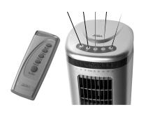
XT610 TOWER FAN |
INSTRUCTIONS |
PLEASE READ THE OPERATING INSTRUCTIONS AND KEEP THEM FOR FUTURE REFERENCE
Power 230 V~
mains frequency: 50 Hz
Capacity: 50 W
7
Dimensions: Ø 112×540 mm
Remote control batteries: 2 AAA / 1.5 Volt
6
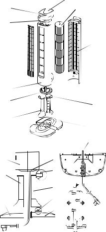
COMPONENTS |
5 |
1Front half of base
2 Front half of column
3Motor support
4 Casing front |
4 |
5Cover screen
6 LED display |
3 |
|
7Control buttons
8 |
Casing cap |
2 |
9 |
Rotor |
|
10Back of casing
11Rear half of column
12Rear half of base
10
11
12
8
9
10
11
12
C
3
B
D
2
A
ASSEMBLY
1Draw the mains lead through the cable duct in the two column halves (2 + 11).
Fit the two halves of the column together.
2Screw column and fan casing together with four cross head screws (M5x12).
Make sure that the small pin (B) fits into the small hole on the motor support.
3Draw the mains lead through the central opening (C) and the cable duct (D) at the rear of the base. Fit the two halves of the base together to complete the base. Screw column and base together with four cross head screws (M5x32). The small metal pin on the front of the base (A) must be fitted into the hole on the base
2
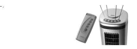
XT610 TOWER FAN |
INSTRUCTIONS |
OPERATING
I)Using the control buttons
1)Press the "ON/OFF" button on the cover gently. The ‘in operation’ lamp lights up.
Then press one or more function buttons
2)Fan function buttons
a)ON/OFF button: Switches the fan on or off.
b)Blowing intensity selector: Settings I, II and III i.e. low, medium or high
c)Operating time selector: there are 15 setting options. Operating time increases by 1⁄2 an hour every time the button is pressed. Maximum operating time setting is 71⁄2 hours
d)Rotation mechanism selector. Starts and stops the rotation movement.
e)Blow mode selector switch: normal, rising and falling, "snooze".
3)LED indicator at the front of the fan and its symbols
I, II and II indicate blowing intensity i.e. low, medium and high "0.5h, 1h, 2h, 4h" shows the operating period selected.
(If several lamps light up = take the sum)  Symbol for natural breeze: The strength
the Tower Fan air current can be set to lig  medium or strong
 Symbol for snooze: With this setting t
 strength of the air current is reduced after
 hour and continues running at “light” until t
Tower Fan is switched off or the set operati time has been reached
II) Using the remote control
The symbols on the remote control correspond to those on the control panel
III) Widening/Narrowing the rotation angle
There are 5 different rotation settings. Stand behind the fan. Grasp the upper part of the fan with both hands and turn gently to the left or right. Every time the fan clicks into place, the rotation angle is increased or decreased by one setting
Accessories included |
|
|
Accessories/Parts |
Size |
Quantity |
Cross head screws |
M5×12 |
5 |
Cross head screws |
M5×32 |
5 |
Remote control (without battery) |
|
|
SAFETY PRECAUTION
Always disconnect the appliance before cleaning or servicing to avoid the risk of fire, shock or injury. To prevent the risk of shock, faulty leads may only be replaced by one of our service agents or a qualified electrician
3
XT610 TURMVENTILATOR |
GEBRAUCHSANLEITUNG |
BITTE GEBRAUCHSANLEITUNG DURCHLESEN UND AUFBEWAHREN
Spannung: 230 V~
Netzfrequenz: 50 Hz
Leistung: 50 W
Abmessungen: Ø 112×540 mm
7
Batterien Fernbedienung: 2 Stk. AAA/1,5 V
6
GERÄTETEILE
5
1 Vordere Standfusshälfte
2Vordere Säulenhälfte
3Motorstütze
4Gehäusefront
5 |
Abdeckgitter |
4 |
|
6 |
LED-Anzeige |
3 |
|
7 |
Steuertasten |
||
|
8Geräteabdeckung
9 |
Propeller |
2 |
10Gehäuserückteil
11Hintere Säulenhälfte
12Hintere Standfusshälfte
10
11
12
MONTAGEANLEITUNG
8
9
10
11
12
C
3
B
D
2
A
1Das Netzkabel durch den Kabelkanal an den Säulenhälften (2 + 11) ziehen. Beide
Säulenhälften zu einer Säule zusammenfügen.
2Säule und Ventilatorgehäuse mittels vier Kreuzschlitzschrauben (M5x12) miteinander verschrauben. Darauf achten, dass der kleine Stift (B) ins kleine Loch an
der Motorstütze eingeführt wird.
3Das Netzkabel durch die zentrale Öffnung (C) und die Kabelführung (D) an der hinteren Standfusshälfte ziehen. Beide Standfusshälften zu einem Standfuss zusammenfügen. Die Säule und den Standfuss mittels vier Kreuzschlitzschrauben (M5x32) miteinander verschrauben. Der kleine Metallstift am vorderen Stand-
fuss(A) muss dabei ins kleine Loch an der Säulenbasis eingeführt werden
4
XT610 TURMVENTILATOR |
GEBRAUCHSANLEITUNG |
BETRIEBSANLEITUNG
I)Steuerung mit Drucktasten
1)Die"Ein/Aus"-TasteaufderGehäuseabdeckungleichtdrücken.DieBetriebsanzeige leuchtet auf. Anschliessend eine oder mehrere Funktionstasten betätigen
2)Funktionstasten des Ventilators
a)Ein/Aus-Taste: Ventilator einoder ausschalten
b)Wähltaste Blasintensität: Stufe I, II und III, d.h. schwach, mittel und stark
c)Wähltaste Betriebsdauer: 15 Stufen stehen zur Verfügung. Mit jedem Tastendruck erhöht sich die Betriebsdauer um 1⁄2 Stunde. Die maximal einstellbare Betriebsdauer beträgt 71⁄2 Stunden
d)Wähltaste Drehmechanismus: Startet und stoppt die Drehbewegung
e)Wähltaste Blastyp: normal, anund abschwellend, "Schlafen".
3)LED-Anzeige an der Vorderseite des Ventilators und deren Symbole
"I,II und III" zeigt Blasintensität an, d.h. schwach, mittel bzw. stark. "0.5h, 1h, 2h, 4h" zeigt die gewählte Betriebsdauer an
(Leuchten mehrere Anzeigen = Summe bilden)
Symbol für natürlicher Wind: D
Turmventilator verändert die Gebläsestär  beliebig zwischen schwach, mittel und stark
 Symbol für Schlafen: Bei dieser Funkti
  verringert sich die Gebläsestärke nach jewe
1 Stunde und läuft am Schluss auf Stu
„schwach» weiter, bis der Turmventilat abgeschaltet wird oder die gewähl
 Betriebsdauer erreicht ist
II) Steuerung über Fernbedienung
Die Symbole auf der Fernbedienung entsprechen den Symbolen auf dem Gehäusetastenfeld.
III) Vergrössern/Verkleinern des Drehwinkels
Es können 5 verschiedene Drehwinkel eingestellt werden. Stellen Sie sich hinter den Ventilator. Den oberen Teil des Ventilators mit beiden Händen fassen und leicht nach rechts oder links drehen. Jedes Mal, wenn der Ventilator einrastet, wird der Drehwinkel um eine Stufe vergrössert bzw. verkleinert.
Mitgeliefertes Zubehör |
|
|
Name |
Grösse |
Menge |
Kreuzschlitzschrauben |
M5×12 |
5 |
Kreuzschlitzschrauben |
M5×32 |
5 |
Fernbedienung (ohne Batterie) |
|
|
SICHERHEITSHINWEIS
Gerät vor jeder Reinigung bzw. Wartung vom Stromnetz trennen, um Brände, Stromstösse und Verletzungen zu verhindern. Um Stromschläge zu vermeiden, dürfen defekte Stromkabel nur von einer Service-stelle bzw. einer qualifizierten Fachperson ersetzt werden
5
 Loading...