

Page 1

PIIIII"SMS1
Mower
/
gollection
System
Actual product may differ from product pictured above TP 900-5216-02-AT-N
Modelscovered:
48" Model (PIN 63320)
48-VS P/N 3071107
3-BS P/N 3071109
4852-WBS PIN 3071110
52" Model (PIN 63313)
52-VS P/N 3071108
3-BS P/N 3071109
4852-WBS PIN 3071110
61" Model (PIN 63347)
61-VS PIN 3063348
3-BS PIN 3071109
4852-WBS PIN 3071110
Manual No. 7028155 (Rev. 2, 7/14/2006)
Page 2

CllnutlnJllflln$!
You have just purchased one of the finest pieces of outdoor power equipment on the market today. If properly cared for,
your new Z-Vac Mower Collection System will provide years of dependable service. Please read and follow this instruc-
tion manual carefully in order to get the most out of your new equipment.
As you carefully unpack your unit, you will find the following items:
1 Z-Vac Blower Unit
1 Bagger Unit with Mounting Kit
1 Weight Bar Kit
1 Package containing operating manuals and warranty registration
Each product leaves our factory in excellent condition; occasionally, however, some damage may occur during shipment.
If any such damage is found upon initial inspection, immediately notify the transport carrier who delivered your machine,
as they are solely responsible for such damage, as well as any subsequent adjustments necessary.
Before assembly, please take a moment and record your model number and serial number below for future reference (both
numbers are located on the serial tag attached to the blower):
Model number
Serial number
Also be sure to promptly fill out and return the warranty registration enclosed in your manual packet.
Your new unit requires very little assembly. Simply follow the instructions contained within this manual to begin enjoying
the benefits of your new unit.
Page 3

ImPS#TMTI7## CBgJl! Y mttSWl#8 #JIB BgS#f
J$$EmB£1N88R8PELq77N8
TRAINING
-- Read, understand, and follow all instructions in the man-
ual and on the unit before starting. If the operator(s) or
mechanic(s) can not read English it is the owner's responsi-
bility to explain this material to them.
-- Become familiar with the safe operation of the equipment,
operator controls, and safety signs.
--All operators and mechanics should be trained. The
owner is responsible for training the users.
-- Only allow responsible adults, who are familiar with the
instructions, to operate the unit.
-- Never let children or untrained people operate or service
the equipment. Local regulations may restrict the age of the
operator.
-- The owner/user can prevent and is responsible for acci-
dents or injuries occurring to themselves, other people or
property.
PREPARATION
-- Evaluate the terrain to determine what accessories and
attachments are needed to properly and safely perform the
job. Use only accessories and attachments approved by
the manufacturer.
-- Wear appropriate clothing including safety shoes, safety
glasses and ear protection. Long hair, loose clothing or jew-
elry may get tangled in moving parts.
-- Inspect the area where the equipment is to be used and
remove all objects such as rocks, toys and wire, which can
be thrown by the machine.
-- Use extra care when handling gasoline and other fuels.
They are flammable and vapors are explosive.
a) Use only an approved container.
b) Never remove fuel cap or add fuel with the engine run-
ning. Allow engine to cool before refueling. Do not smoke.
c) Never refuel or drain the machine indoors.
-- Check that operator's presence controls, safety switches
and shields are attached and functioning properly. Do not
operate unless they are functioning properly.
OPERATION
-- Never run an engine in an enclosed area.
-- Operate only in the daylight or with good artificial light,
keeping away from holes and hidden hazards.
-- Be sure of your footing while using pedestrian controlled
equipment, especially when backing up. Walk, don't run.
-- Do not operate in reverse unless absolutely necessary.
Always look down and behind before and while traveling in
reverse.
-- Be aware of the blower discharge direction and do not
point it at anyone. Do not operate the blower without hose
and bagger hood in place.
-- Never leave a running unit unattended. Always stop
engine before leaving unit.
-- Never operate with guards not securely in place. Be sure
all safety features are attached, adjusted properly and func-
tioning properly.
-- Never operate with the hose or hood removed or altered.
-- Do not change the engine governor setting or over speed
the engine.
-- Stop on level ground, shut off engine before leaving the
operator's position for any reason.
-- Stop equipment and inspect impeller blades after striking
objects or abnormal vibration occurs. Make necessary
repairs before resuming operations.
-- Keep hands and feet away intake and discharge areas.
-- Keep pets and bystanders away.
-- Do not operate the unit while under the influence of alco-
hol or drugs.
-- Use caution when crossing roads and sidewalks. Stop
engine if not blowing.
-- Use care when loading or unloading the machine into a
trailer or truck.
-- Use care when approaching blind corners, shrubs, trees
or other objects that may obscure vision.
SLOPE OPERATION
Slopes are a major factor related to loss-of-control and tip-
over accidents, which can result in severe injury or death.
All slopes require extra caution. If you cannot back up the
slope, or if you feel uneasy on it, do not drive on it.
Do
-- Mow up and down slopes, never across face.
-- Remove obstacles such as rocks, tree limbs, etc.
-- Watch for holes, ruts, or bumps. Uneven terrain could
overturn the unit. Tall grass can hide obstacles.
-- Keep all movement on the slopes slow and gradual. Do
not make sudden changes in speed or direction.
Do Not
-- Do not start or stop on a slope. If tires lose traction, pro-
ceed slowly straight down the slope.
-- Do not turn on slopes unless necessary, and then, turn
slowly and gradually downhill, if possible.
-- Do not use near drop-offs, ditches, or embankments. The
operator could lose footing or balance or blower could sud-
denly turn over if a wheel is over the edge of a cliff or ditch,
or if an edge caves in.
-- Do not operate on slopes with wet grass. Reduced foot-
ing or traction could cause sliding.
-- Do not operate machine on slopes in excess of 10
degrees (18% grade) when equiped with a grass catcher.
-- Do not operate machine without weight kit installed when
equiped with a grass catcher.
Page 4

CHILDREN
Tragic accidents can occur if the operator is not alert to the
presence of children. Children are often attracted to the unit
and its activity. Never assume that children will remain
where you last saw them.
-- Keep children out of the mowing area and under the
watchful care of another responsible adult.
-- Do not allow children or others to ride on the machine,
attachment, or towed equipment (even with the blades off).
-- Be alert and turn unit off if children enter the area.
-- Before and during reverse operation, look behind and
down for small children.
-- Never allow children to operate the unit.
-- Use extra care when approaching blind corners, shrubs,
trees, or other objects that may obscure vision.
EMISSIONS
-- Engine exhaust from this product contains chemicals
known, in certain quantities, to cause cancer, birth defects,
or other reproductive harm.
-- Look for the relevant Emissions Durability Period and Air
Index information on the engine emissions label.
MAINTENANCE AND STORAGE
--Always observe safe refueling and fuel handling practices
when refueling the unit after transportation or storage.
-- Always follow the engine manual instructions for storage
preparations before storing the unit for both short and long
term periods.
--Always follow the engine manual instructions for proper
start-up procedures when returning the unit to service.
-- Never store the machine or fuel container inside where
there is an open flame, such as in a water heater. Allow unit
to cool before storing.
-- Shut off fuel while storing or transporting. Do not store fuel
near flames or drain indoors.
-- Keep all hardware tight and keep all parts in good work-
ing condition. Replace all worn or damaged decals.
-- Never tamper with safety devices. Check their proper
operation regularly.
-- Clean leaves and debris from mufflers and engine to pre-
vent fires. Clean up oil or fuel spillage.
-- Stop and inspect the equipment if you strike an object.
Repair, if necessary, before restarting.
-- Never make adjustments or repairs with the engine run-
ning unless specified otherwise.
-- Park machine on level ground. Never allow untrained per-
sonnel to service machine.
-- Carefully release pressure from components with stored
energy. (e.g. springs)
-- Only replace impellers. Never straighten or weld them.
-- Keep hands and feet away from moving parts.
-- Frequently check components and replace with manufac-
turer's recommended parts, when necessary.
-- Use only factory authorized replacement parts when mak-
ing repairs.
-- Always comply with factory specifications on all settings
and adjustments.
-- Only authorized service locations should be utilized for
major service and repair requirements.
-- Never attempt to make major repairs on this unit unless
you have been properly trained. Improper service proce-
dures can result in hazardous operation, equipment dam-
age and voiding of manufacturer's warranty.
Page 5
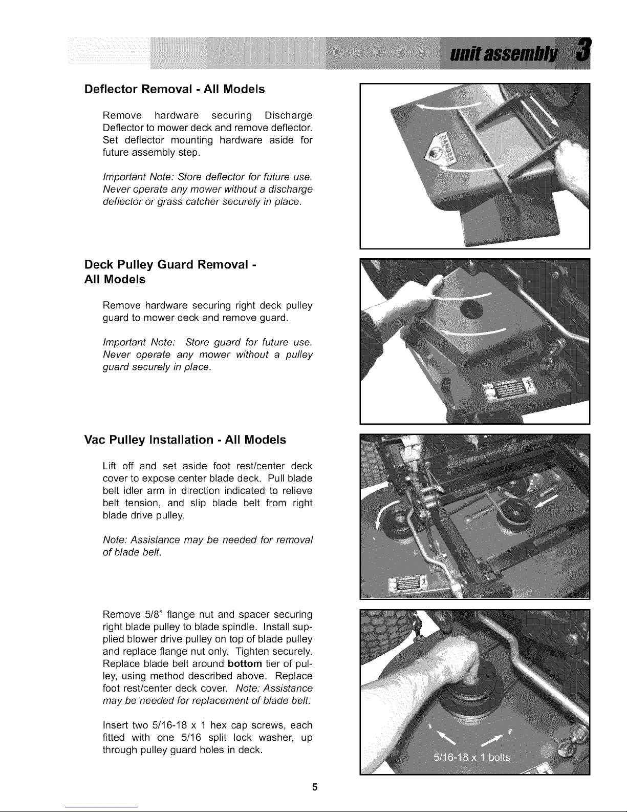
Deflector Removal - All Models
Remove hardware securing Discharge
Deflector to mower deck and remove deflector.
Set deflector mounting hardware aside for
future assembly step.
Important Note: Store deflector for future use.
Never operate any mower without a discharge
deflector or grass catcher securely in place.
Deck Pulley Guard Removal -
All Models
Remove hardware securing right deck pulley
guard to mower deck and remove guard.
Important Note: Store guard for future use.
Never operate any mower without a pulley
guard securely in place.
Vac Pulley Installation -All Models
Lift off and set aside foot rest/center deck
cover to expose center blade deck. Pull blade
belt idler arm in direction indicated to relieve
belt tension, and slip blade belt from right
blade drive pulley.
Note: Assistance may be needed for removal
of blade belt.
Remove 5/8" flange nut and spacer securing
right blade pulley to blade spindle. Install sup-
plied blower drive pulley on top of blade pulley
and replace flange nut only. Tighten securely.
Replace blade belt around bottom tier of pul-
ley, using method described above. Replace
foot rest/center deck cover. Note: Assistance
may be needed for replacement of blade belt.
Insert two 5/16-18 x 1 hex cap screws, each
fitted with one 5/16 split lock washer, up
through pulley guard holes in deck.
5
Page 6
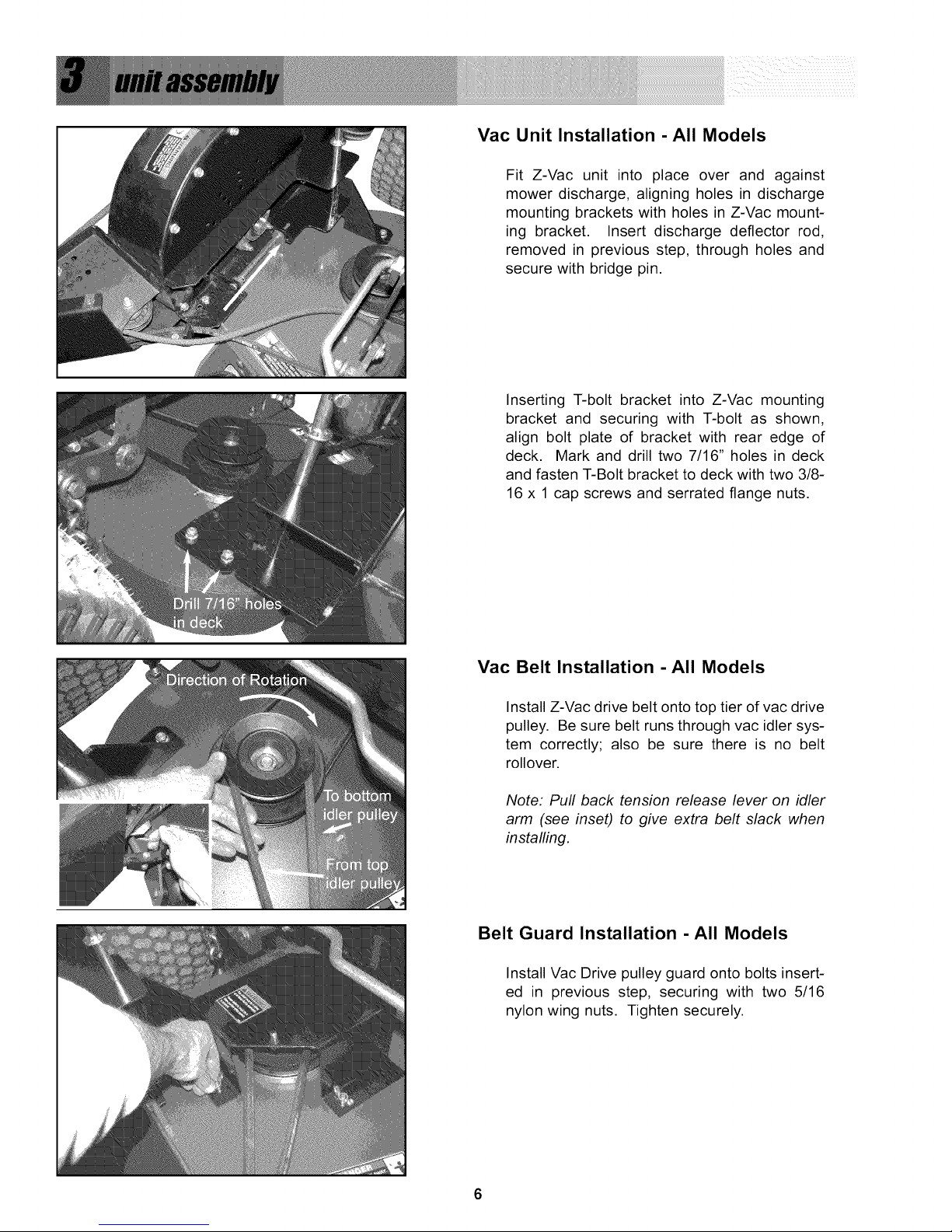
Vac Unit Installation -All Models
Fit Z-Vac unit into place over and against
mower discharge, aligning holes in discharge
mounting brackets with holes in Z-Vac mount-
ing bracket. Insert discharge deflector rod,
removed in previous step, through holes and
secure with bridge pin.
Inserting T-bolt bracket into Z-Vac mounting
bracket and securing with T-bolt as shown,
align bolt plate of bracket with rear edge of
deck. Mark and drill two 7/16" holes in deck
and fasten T-Bolt bracket to deck with two 3/8-
16 x 1 cap screws and serrated flange nuts.
Vac Belt Installation -All Models
Install Z-Vac drive belt onto top tier of vac drive
pulley. Be sure belt runs through vac idler sys-
tem correctly; also be sure there is no belt
rollover.
Note: Pull back tension release lever on idler
arm (see inset) to give extra belt slack when
installing.
Belt Guard Installation -All Models
Install Vac Drive pulley guard onto bolts insert-
ed in previous step, securing with two 5/16
nylon wing nuts. Tighten securely.
6
Page 7
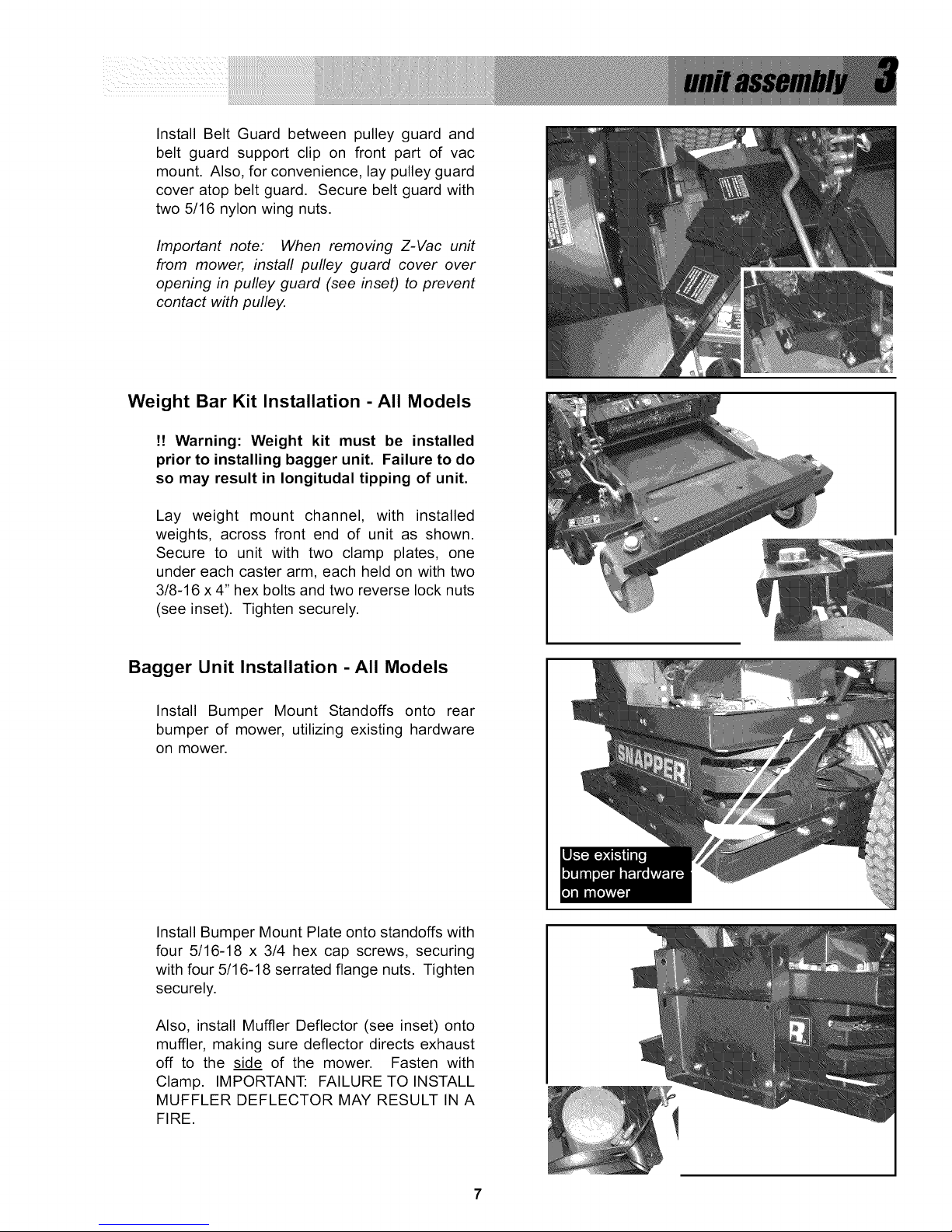
InstallBeltGuardbetweenpulleyguardand
beltguardsupportclip on frontpartof vac
mount,Also,forconvenience,laypulleyguard
coveratopbeltguard,Securebeltguardwith
two5/16nylonwingnuts,
Important note: When removing Z-Vac unit
from mower, install pulley guard cover over
opening in pulley guard (see inset) to prevent
contact with pulley.
Weight Bar Kit Installation - All Models
!! Warning: Weight kit must be installed
prior to installing bagger unit. Failure to do
so may result in Iongitudal tipping of unit.
Lay weight mount channel, with installed
weights, across front end of unit as shown.
Secure to unit with two clamp plates, one
under each caster arm, each held on with two
3/8-16 x 4" hex bolts and two reverse lock nuts
(see inset). Tighten securely.
Bagger Unit Installation -All Models
Install Bumper Mount Standoffs onto rear
bumper of mower, utilizing existing hardware
on mower.
Install Bumper Mount Plate onto standoffs with
four 5/16-18 x 3/4 hex cap screws, securing
with four 5/16-18 serrated flange nuts. Tighten
securely.
Also, install Muffler Deflector (see inset) onto
muffler, making sure deflector directs exhaust
off to the side of the mower. Fasten with
Clamp. IMPORTANT: FAILURE TO INSTALL
MUFFLER DEFLECTOR MAY RESULT IN A
FIRE.
7
Page 8
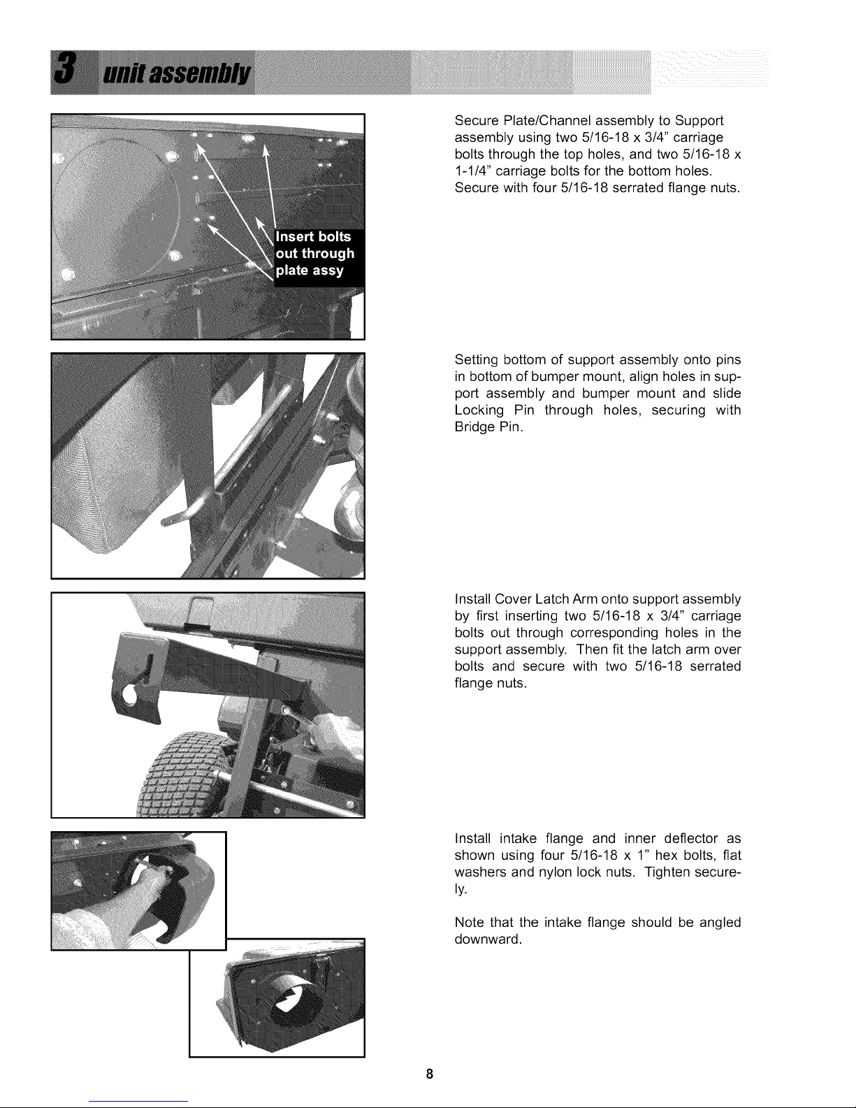
SecurePlate/ChannelassemblytoSupport
assemblyusingtwo5/16-18x3/4"carriage
boltsthroughthetopholes,andtwo5/16-18x
1-1/4"carriageboltsforthebottomholes.
Securewithfour5/16-18serratedflangenuts.
Settingbottomofsupportassemblyontopins
inbottomofbumpermount,alignholesinsup-
portassemblyandbumpermountandslide
LockingPin throughholes, securingwith
BridgePin.
InstallCoverLatchArmontosupportassembly
byfirstinsertingtwo 5/16-18x 3/4"carriage
boltsoutthroughcorrespondingholesin the
supportassembly.Thenfitthelatcharmover
boltsandsecurewithtwo 5/16-18serrated
flangenuts.
Installintakeflangeand innerdeflectoras
shownusingfour5/16-18x 1"hexbolts,flat
washersandnylonlocknuts.Tightensecure-
ly.
Notethattheintakeflangeshouldbeangled
downward.
8
Page 9

Bagger Unit Installation (Cont.)
Set cover on plate assembly, aligning hinges in
cover with hinges on plate. Secure with three
3/8 x 2-3/4" clevis pins and 1-3/4" oal bridge
pins.
Not Shown: Install Cover Handle (See Parts List, 3-
Bag Catcher Group (Sheet 5), Ref #47) onto cover
assembly with eight #8-32 x 1/2" round head
machine screws, and securing with #8 flat washers,
split lock washers, and #8-32 hex machine nuts.
Tighten securely.
Lift cover and install bags onto plate/channel
assembly by hooking slot in bag hanger onto
tabs in channel assembly.
Close cover and lock in place by hooking lock
knob into slot in cover latch arm.
Discharge Hose Installation -All
Models
Slip one hose clamp onto each end of hose
(use the clamp with the quick-release knob at
the blower end), and install hose between unit
and bagger, making careful note of direction
sticker inside end of hose (see inset). Tighten
clamps securely.
.....
9
Page 10

Assembly is complete. Refer to the operator's manual of your rider for the I
safest and most effective use of your new unit. I
DOmmm
...Inspectunitbeforeeach use to be sure allfastenersare securelytightened
and allcomponents are securelyinplace.
...Be aware that installed blower unit engages along with mower deck - never
operate mower without hose, cover and bags in place.
...Inspect unit often for wear and damage. Replace worn or damaged items
promptly.
...Grease bearing units regularly with a quality lithium grease.
DONOT..
...Operate the rider without the weight channel and bars installed.
of rider can result.
...Operate the unit without belt guards securely in place. Serious injury may
result.
...Overfill bags. A good rule of thumb is to empty bags at about 3/4 capacity.
...Store unit with bags full. Stretching and eventual tearing of bag material may
result.
Rear tipping
10
Page 11
2 YEAR LIMITED WARRANTY
For two (2) years from purchase date for the original purchaser's residential, non-commercial use, SNAPPER, through any
authorized SNAPPER dealer will replace, free of charge (except for taxes where applicable), any part or parts found upon
examination by the factory at McDonough, Georgia, to be defective in material or workmanship or both.
For one (1) year from purchase date for the original purchaser's commercial, non-residential use, SNAPPER, through any
authorized SNAPPER dealer will replace, free of charge, any part or parts found upon examination by the factory at
McDonough, Georgia, to be defective in material or workmanship or both.
For ninety (90) days from purchase date for the original purchaser's rental use, SNAPPER, through any authorized SNAP-
PER dealer will replace, free of charge, any part or parts found upon examination by the factory at McDonough, Georgia,
to be defective in material or workmanship or both
All transportation costs incurred by the purchaser in submitting material to an authorized SNAPPER dealer for replace-
ment under this warranty must be paid by the purchaser.
This warranty does not apply to certain transmissions, to engines and their components, and batteries, as these items are
warranted separately. This warranty does not apply to parts that have been damaged by accident, alteration, abuse,
improper lubrication, normal wear, or other cause beyond the control of SNAPPER. This warranty does not cover any
machine or component part that has been altered or modified changing safety, performance, or durability.
Batteries have a one (1) year warranty period with free replacement if required for one (1) year from the original purchase
date. SNAPPER will not be responsible for any installation cost incurred. The battery warranty only covers original equip-
ment batteries and does not cover damage to the battery or machine caused by neglect or abuse, destruction by fire,
explosion, freezing, overcharging, improper maintenance, or use of improper electrolyte.
There is no other express warranty.
DISCLAIMER OF WARRANTY
Implied warranties, including those of merchantability and fitness for a particular purpose, are limited to two (2) years from
purchase date for the original purchaser's residential or other non-commercial use, and one (1) year from purchase for the
original purchaser's commercial, non-residential use, and ninety (90) days from purchase for the original purchaser's rental
use and to the extent permitted by law, any and all implied warranties are excluded. This is the exclusive remedy. Liabilities
for consequential damages, under any and all warranties are excluded.
Some states do not allow limitations on how long an implied warranty lasts, or do not allow the exclusion or limitation of
incidental or consequential damages, so the above limitation or exclusion may not apply to you.
This warranty gives you specific legal rights, and you may also have other rights which vary from state to state.
WARNING: THE USE OF REPLACEMENT PARTS OTHER THAN GENUINE SNAPPER PARTS MAY IMPAIR THE
SAFETY OF SNAPPER PRODUCTS AND WILL VOID ANY LIABILITY AND WARRANTY BY SNAPPER ASSOCIATED
WITH THE USE OF SUCH PARTS.
IMPORTANT: Please fill out the SNAPPER Product Registration Card immediately and mail to:
Snapper's Product Registration Center, RO. Box 1379, McDonough, Georgia 30253
11
Page 12

3O
17
T
18
14
22
15
16
I
I
I
Q 2s
I
25
k
26
24
20
12
19
/
17
SNAPPER
Z-VAC
BLOWER GROUP
Models 48-VS, 52-VS, 61-VS
* Grease Fitting Orientation
Page 13

aRet l41a¢Bedel$ -IFJ, #2-1FJ,81-1FJ
Item
1
2
3
4
5
6
7
8
9
10
11
12
13
14
15
16
17
17
18
18
19
19
20
21
21
22
23
24
25
26
27
28
29
30
Pa_ No.
3046782
91121
90250*
3021097
35816
91804
14409
91598
3046824
91527
3047253
91601
91218
3046781
3046853
91541
3022832
7100021
90839
91601
3031920
91508
3046854
3031919
91508
90613
3046813
35867
90122
91560
91518
91305
92111
91541
Qty
1
1
1
1
1
2
2
1
1
1
1
1
1
1
1
5
2
2
8
6
4
3
1
4
3
2
2
2
9
2
1
1
3
3
Description
WELDMENT, Blower Belt Guard
NUT, 1/2-13 Hex Nyloc
WASHER, 1/2" Flat SAE
PULLEY, A Groove Idler, Steel
IDLER STUD (3/8-24 thread)
FLAT WASHER, 9/16 Type Narrow
FLANGE BEARING, 9/16" I.D. (powdered metal)
PIN, 1/8 x 3/4" Cotter
BELT RETAINER, Idler
SCREW, 5/16-18 x 1-1/4" Hex Head Cap, GR5
WELDMENT, Idler Arm
NUT, 5/16-18 Hex Flange Lock
SCREW, 1/2-13 x 2-1/2" Hex Head Cap, GR5
WELDMENT, Blower Housing
BACK PLATE, Blower
SCREW, 5/16-18 x 3/4" Hex Washer Self-Tap
BEARING, 4-Bolt Pillow Block, Blower (Some 2005 models & all older models;
includes grease fitting)
BEARING, 3-Bolt Flange (Some 2005 models & all 2006 models)
NUT, 7/16-14 Hex Center Lock, GR5 or B (Some 2005 models &
all older models)
NUT, 5/16-18 Flange Lock (Some 2005 models & all 2006 models)
SCREW, 7/16-14 x 1-1/2" Hex Head Cap, GR5 (Some 2005 models &
all older models)
BOLT, 5/16-18 x 3/4" Carriage (Some 2005 models & all 2006 models)
IMPELLER, Fast Vac Blower (weldment)
SCREW, 7/16-14 x 1-1/4" Hex Head Cap, GR5 (Some 2005 models &
all older models)
BOLT, 5/16-18 x 3/4" Carriage (Some 2005 models & all 2006 models)
NUT, 3/8-16 Hex Flange Lock
BELT RETAINER
PULLEY, Flat Idler, 2-3/4" O.D.
WASHER, 3/8" Flat SAE
SCREW, 3/8-16 x 2-1/4" Hex Head Cap, GR5
NUT, 3/8-24 Hex Nyloc
SCREW, 3/8-16 x 2" Hex Head Cap, GR5
U-CLIP, 5/16-18
SCREW, 5/16-18 x 3/4" Hex Washer Self-Tap
13
Page 14

120
%
\
\
I
/
8
SNAPPER
Z-VAC
BLOWER MOUNT GROUP
Models 48-VS, 52-VS, 61-VS
14
Page 15

, aBnr l-m¢ .Bedel$ -IFJ, 52-1FJ,81-1FJ
Item
1
1
2
2
3
4
5
5
5
6
6
7
8
8
8
9
10
11
12
13
14
15
16
17
18
19
2O
21
PaN No.
3036323
3022844
3037161
3033867
91527
91537
3037162
3037163
3033847
3046806
3046809
3036324
3027505
3027506
3033873
3027507
91541
3027508
91304*
90613
3032118
27168*
91601
91067
3020807
12315
91617
90951*
Qty.
1
1
1
1
2
4
1
1
1
1
1
1
1
1
1
1
4
1
2
4
1
2
1
2
1
1
1
2
Description
BELT, A Section, 91.125" effective length (used on 48-VS & 52-VS)
BELT, A Section, 92.0" effective length (used on 61-VS)
WELDMENT, Belt Cover, Deck (used on 48-VS & 52-VS)
WELDMENT, Belt Cover, Deck (used on 61-VS)
SCREW, 5/16-18 x 1-1/4" Hex Head Cap, GR5
WING LOCKNUT 5/16-18
BELT GUARD, 48" Deck
BELT GUARD, 52" Deck
BELT GUARD, 61" Deck
PULLEY, Blower Input, 48" & 52"
PULLEY, Blower Input, 61"
PULLEY, 48"/52" Spindle
WELDMENT, 48" Blower Mount
WELDMENT, 52" Blower Mount
WELDMENT, 61" Blower Mount
WELDMENT, Guard Support Bracket
SCREW, 5/16-18 x 3/4" Hex Washer Self-Tap
WELDMENT, Deck Mount Bracket
SCREW, 3/8-16 x 1" Hex Head Cap, GR5
NUT, 3/8-16 Hex Flange Lock
WELDMENT, T-Handle Pin
SCREW, 5/16-18 x 1" Hex Head Cap, GR5
NUT, 5/16-18 Hex Flange Lock
NUT, 5/16-18 Hex Center Lock, GR B
SPRING, Idler, Fast Vac
KEY, 1/4 Square x 1.44
SCREW, 3/8-16 x 6" Hex Head Cap, GR5
NUT, 5/16-18 Hex Large Flange Center Lock
15
Page 16
31
3!
35
34
33
36
I
8
26
25
23
27
26
1
29
27
28
19
18
15
9
10
t 11
12
13
/
14
SNAPPER
'Z.VAC'
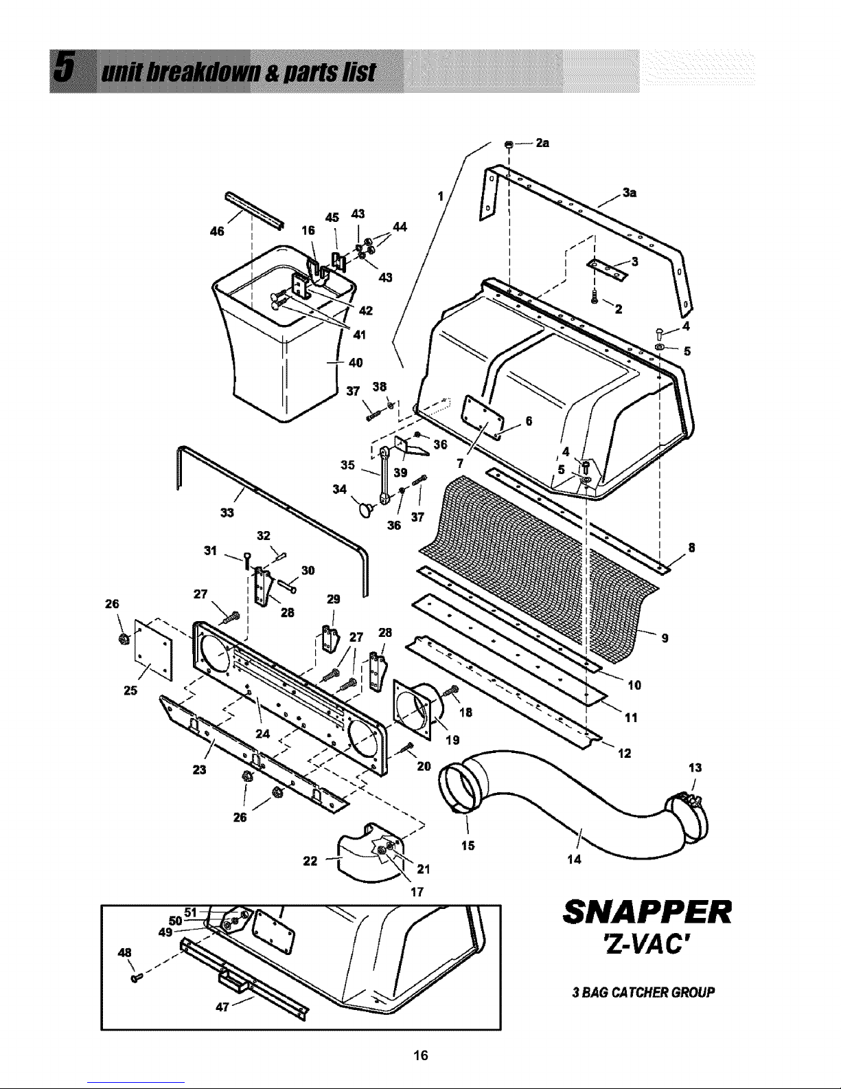
3 BAG CATCHERGROUP
16
Page 17
Item
1
2
2
2A
3
3A
4
5
6
7
8
9
10
11
12
13
14
15
16
17
18
19
20
21
22
23
24
25
26
27
28
29
30
31
32
33
34
35
36
37
38
39
40
41
42
43
44
45
46
47
48
49
50
51
Pa_ No.
3046862
91495
79405
91584
1717067
3027475
76958
1910531*
1667248
1704405
1716970
1717041
1717524
1716968
1716972
3022876
3022833
3022875
1703855
91298
90636
3046801
91122
91130*
1717039
1716973
1716966
1717037
91601
91318
1720875
1720945
1672344
91809
3022834*
1717082
3022838
3021670
90376
90922
91702
3046832
7030847
90316
1703807
90187
91511
1672023
1675707
3027476
92117
3031985*
92116
91018*
1
9
4
13
3
1
25
16
6
1
1
1
1
1
1
1
1
1
3
4
4
1
3
4
1
1
1
1
6
6
2
1
3
3
16
1
1
1
2
2
1
1
3
6
3
6
6
3
3
1
8
8
8
8
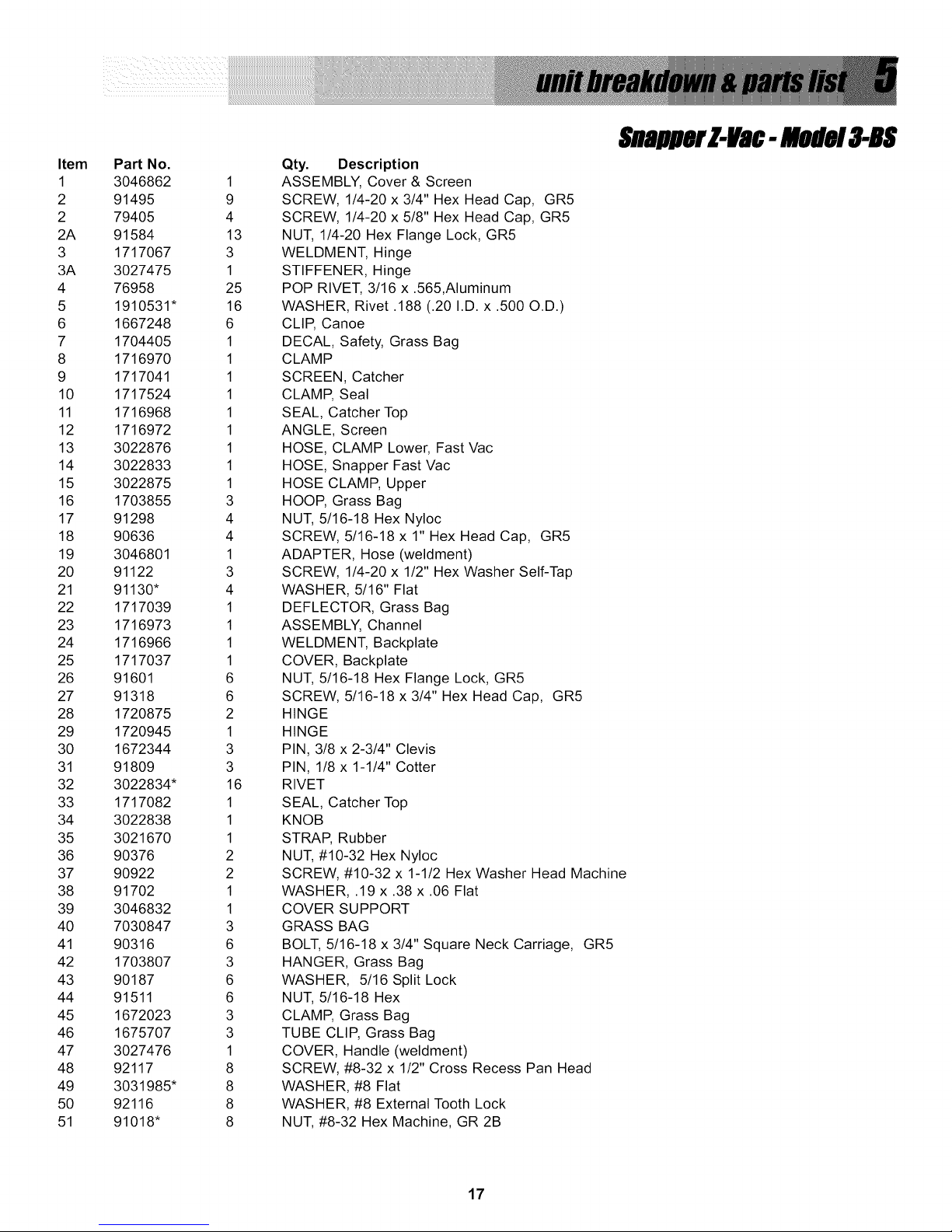
, uBmrl-itBc- mede!a-B$
Qty. Description
ASSEMBLY, Cover & Screen
SCREW, 1/4-20 x 3/4" Hex Head Cap, GR5
SCREW, 1/4-20 x 5/8" Hex Head Cap, GR5
NUT, 1/4-20 Hex Flange Lock, GR5
WELDMENT, Hinge
STIFFENER, Hinge
POP RIVET, 3/16 x .565,Aluminum
WASHER, Rivet .188 (.20 I.D. x .500 O.D.)
CLIP, Canoe
DECAL, Safety, Grass Bag
CLAMP
SCREEN, Catcher
CLAMP, Seal
SEAL, Catcher Top
ANGLE, Screen
HOSE, CLAMP Lower, Fast Vac
HOSE, Snapper Fast Vac
HOSE CLAMP, Upper
HOOP, Grass Bag
NUT, 5/16-18 Hex Nyloc
SCREW, 5/16-18 x 1" Hex Head Cap, GR5
ADAPTER, Hose (weldment)
SCREW, 1/4-20 x 1/2" Hex Washer Self-Tap
WASHER, 5/16" Flat
DEFLECTOR, Grass Bag
ASSEMBLY, Channel
WELDMENT, Backplate
COVER, Backplate
NUT, 5/16-18 Hex Flange Lock, GR5
SCREW, 5/16-18 x 3/4" Hex Head Cap, GR5
HINGE
HINGE
PIN, 3/8 x 2-3/4" Clevis
PIN, 1/8 x 1-1/4" Cotter
RIVET
SEAL, Catcher Top
KNOB
STRAP, Rubber
NUT, #10-32 Hex Nyloc
SCREW, #10-32 x 1-1/2 Hex Washer Head Machine
WASHER, .19 x .38 x .06 Flat
COVER SUPPORT
GRASS BAG
BOLT, 5/16-18 x 3/4" Square Neck Carriage, GR5
HANGER, Grass Bag
WASHER, 5/16 Split Lock
NUT, 5/16-18 Hex
CLAMP, Grass Bag
TUBE CLIP, Grass Bag
COVER, Handle (weldment)
SCREW, #8-32 x 1/2" Cross Recess Pan Head
WASHER, #8 Flat
WASHER, #8 External Tooth Lock
NUT, #8-32 Hex Machine, GR 2B
17
Page 18
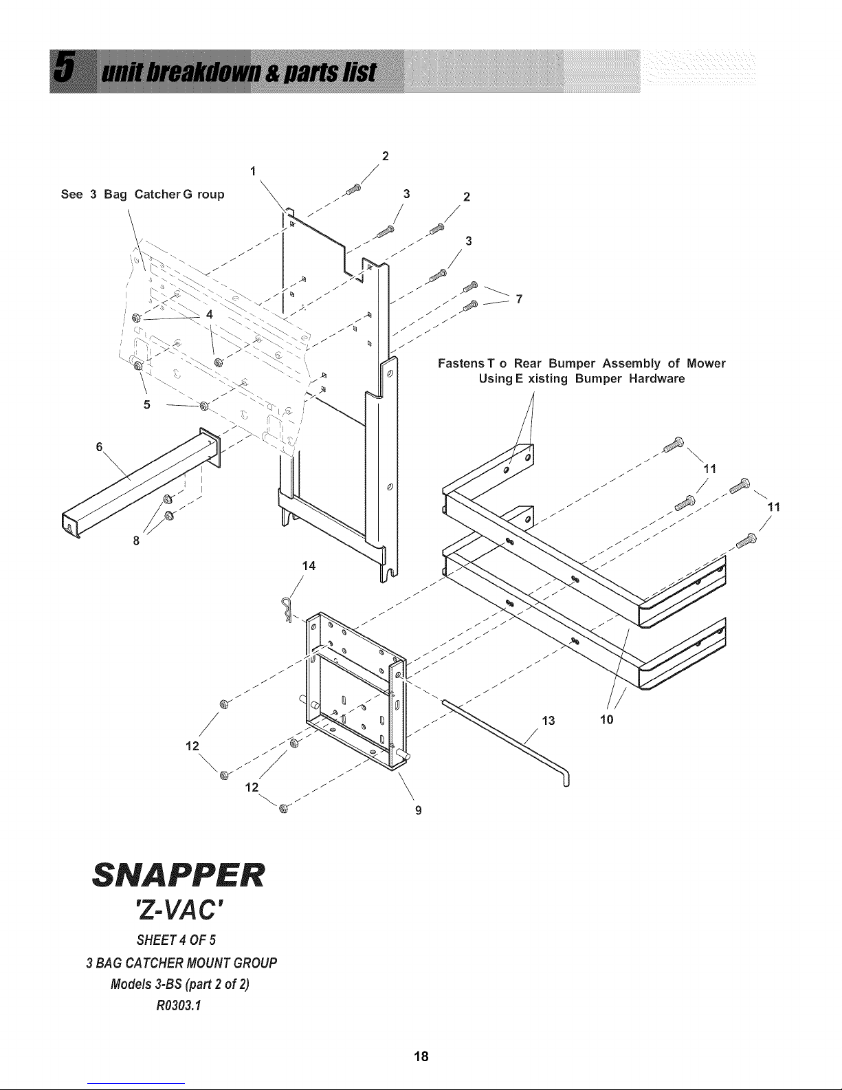
See 3 Bag CatcherG roup
6
\
3 2
/ /
Fastens T o Rear Bumper Assembly of Mower
Using E xisting Bumper Hardware
'Z-VAC'
SHEET4 OF5
3 BAG CATCHERMOUNTGROUP
Models 3-BS (part 2of 2)
R0303.I
10
18
Page 19

$nBllK l41a¢. Bedela-B$
Item
1
2
3
4
5
6
7
8
9
10
11
12
13
14
Part No.
3027509
90316
90978
91601
91601
3046831
90316
91601
1723436
3027510
91318
91601
1717085
15067
Qty.
1
2
2
2
2
1
2
2
1
2
4
4
1
1
Description
WELDMENT, Catcher Support
BOLT, 5/16-18 x 3/4" Square Neck Carriage, GR5
BOLT, 5/16-18 x 1-1/4" Square Neck Carriage, GR5
NUT, 5/16-18 Hex Flange Lock, GR5
NUT, 5/16-18 Hex Flange Lock, GR5
ARM, Cover Latch (weldment)
BOLT, 5/16-18 x 3/4" Square Neck Carriage, GR5
NUT, 5/16-18 Hex Flange Lock, GR5
WELDMENT, Bumper Mount Plate
STANDOFF, Bumper Mount (weldment)
SCREW, 5/16-18 x 3/4" Hex Head Cap, GR5
NUT, 5/16-18 Hex Flange Lock, GR5
ROD, Hitch
HAIR PIN, 3/32 x 1-1/2" Cotter
19
Page 20

t t
1 I
1
Mower Caster Arms
SNAPPER
'Z-VA C "
WEIGHT MOUNT GROUP
/
2O
Page 21

._Blmr Z41ac-Be#el4852.1fiBS
Item
1
2
3
4
5
6
7
8
Pa_ No.
3027501
3046992
91131
90546
3027502
3031021
90619
3032142
Qty.
1
2
4
4
13
3
3
2
Description
CHANNEL, Weight Mounting
BAR, Clamp
BOLT, 3/8-16 x 4" Hex Tap, GR5
NUT, 3/8-16 Hex Center Lock, GR5 or B
BAR, Weight
SCREW, 1/2-13 x 4-1/2" Hex Head Cap
NUT, 1/2-13 Hex Flange Lock
PAD, Anti-Skid, Self-Adhesive
21
Page 22

2
\
3
5
NOTE:
Decals are not to scale.
22
Page 23

$nallllKl41a¢
Item
1
2
3
4
5
PaN No.
3079231
1704405
3046850
3046851
3046883
Qty
1
1
1
1
1
Description
DECAL, Z-Vac
DECAL, Safety, Grass Bag
DECAL, Danger, Fast-Vac
DECAL, Warning, Fast Vac
DECAL, Warning, Fast-Vac
23
Page 24

McDonough, GA 30253 U.S.A.
Manual No. 7028155 (Rev. 2, 7/14/2006)
TP 900-5216-02-AT-N
 Loading...