


SET-UP INSTRUCTIONS & PRE-OPERATION CHECKLIST SNAPPER ZERO TURNING Z-RIDER with MID MOUNT MOWER
INTRODUCTION: These instructions cover the set-up of the Snapper Mid Mount Z-Rider Mower. Complete each of the following steps carefully. Review and complete each item as instructed on the Pre-Operation checklist. The Snapper Product Registration card must be filled out and sent to Customer Service department at Snapper when completed.
IMPORTANT: The battery for this unit is shipped dry. A package of battery acid (electrolyte) will have to be purchased separately. Allow sufficient time for charging and installing the battery before operating the rider. Pay close attention to the precautionary statements on the battery and in these instructions. You will also need an automotive type battery charger to activate the battery for use.
STEP 1: Remove machine from the container. The battery will have to be charged and installed.
STEP 2: Remove battery from the battery compartment before charging.
STEP 3: Place battery in a well ventilated area on a level non-concrete surface.
WARNING
The electrolyte (acid) produces a highly explosive gas. Keep all sparks, flame and fire away from area when charging battery or when handling electrolyte or battery. Electrolyte (acid) is a highly corrosive liquid. Wear eye protection. Wash affected areas immediately after having eye or skin contact with electrolyte (acid). Battery acid is corrosive. Rinse empty acid containers with water and mutilate before discarding. If acid is spilled on battery, bench, or clothing, etc., Flush with clear water and neutralize with baking soda.
STEP 4: Remove battery cell caps. Fill cells as required with electrolyte (purchased separately) to proper level. Filling battery with electrolyte will bring the battery to 80% charged state.
WARNING
DO NOT OVERFILL!
STEP 5: With cell caps removed, connect battery charger to battery terminals; RED to positive (+) and BLACK to negative (-) terminal.
STEP 6: Slow charge the battery at 2 amp for 2 hours to bring the battery to full charge.
STEP 7: After charging, check level of electrolyte and add as needed to bring fluid to proper level.
STEP 8: Reinstall cell caps.
STEP 9: Install battery into power unit.
STEP 10: Both bolts are already installed on both terminals. Connect positive (+) cable (red) first, from wiring harness to the positive terminal (+) on battery and secure with nut provided in hardware bag. Connect negative (-) cable (black) last, to negative terminal (-) on battery and secure with nut also provided. Apply a small amount of grease over terminals to prevent corrosion. See Figure 1.
WARNING
Shield the positive terminal with terminal cover located on battery harness. This prevents metal from touching the positive terminal, which could cause sparks.
RED (POSITIVE) CABLE |
BLACK (NEGATIVE) CABLE |
TERMINAL COVER MUST
SHIELD POSITIVE
TERMINAL AFTER
INSTALLATION
FIGURE 1
STEP 11: Take the necessary precautions, when handling fuel. Fill the fuel tank with clean fuel. Check oil and add oil if needed as stated in Engine Owners Manual. Move fuel tank selector valve handle to the desired fuel tank.
INSTRUCTION No. 7-5597 (I.R. 4/1/03)
WARNING
Handle fuel with care! Use an approved fuel container. DO NOT smoke near open fuel container and keep fuel container away from open flame. DO NOT fill fuel tank indoors or when engine is running. Allow engine to cool for at least ten minutes before refilling. Wipe off any spilled fuel before starting engine. DO NOT run engine indoors. Before attempting any adjustments, maintenance, service, or repairs, stop engine and blade, always remove key from ignition switch, remove spark plug wire(s) and secure wire(s) away from spark plug(s).
STEP 12: MOWER DECK ADJUSTMENT (LEVELNESS) SIDE to SIDE and FRONT to REAR
Before making deck leveling adjustments, inflate rear tires to 12 PSI and front tires to 25 PSI. When adjusted correctly, the deck will be level side to side within 1/8”, have a low cut setting of approximately 1” and the blades pitched approximately 3/16” higher at the rear.
A.Place machine on a smooth level surface.
B.Check blade tips by rotating blades until tips are pointing to the sides of the deck. Check the measurement of outside blade tips to the ground on both blades. The measurement of each of the outside blade tips should be within 1/8” of each other. If measurement of the blade tips is not within 1/8”, adjustment should be made to the correct measurement.
C.Move deck lift lever and set the mower deck to the highest cutting position.
D.Relieve tension on deck lift assist spring by loosening nut on eyebolt.
E.Place 1” blocks under the front and rear edge of the mower deck.
F.Move deck lift lever and set the mower deck to a lower cutting position until deck rests on the 1” blocks.
G.Loosen the nuts and bolts that secure both front deck support chains. Adjust chains until tight and retighten bolts and nuts. Torque to 70 ft. lbs.
H.Loosen the nuts that secure both rear deck support eyebolts. Adjust to remove slack from both rear chains. Tighten nuts securely.
I.Move deck lift lever and set the mower deck to the highest cutting position and recheck side to side blade tip dimensions. The difference between the two should be 1/8” or less.
NOTE: The deck timing rod is preset at the factory and requires no adjustments.
J.The leveling blocks used in Step E should result in a proper deck pitch. If a pitch adjustment is required, use the two rear deck support eyebolts. Adjust up or down as required.
K.Reinstall deck lift assist spring. Place deck in highest cutting position. Tighten nut on eyebolt until 1 1/4” of threads protrude past end of nut.
STEP 13: HYDRAULIC OIL RESERVOIRS
Check the level of the fluid in both of the fluid reservoirs. The reservoirs are located underneath the operator’s seat. Wipe away all dirt and debris from around reservoir cap before removing. Oil must remain absolutely clean! Check with machine on a level surface with engine “OFF”. Fill reservoir as needed to bring level up. The reservoir is properly filled when the fluid level is 1½” below the top of the filler neck. DO NOT OVER FILL. Use clean, fresh premium automotive oil having a viscosity equivalent to SAE 20W50 API SL. The fluid should be chemically stable, incorporating rust and oxidation inhibitors. Make sure funnels, pouring spouts and oil can are completely clean. Reinstall reservoir cap.
IMPORTANT: Re-check fluid level after operating machine for several minutes and adjust level as needed. If one or both of the wheel drive systems is not pulling properly, the hydraulic system may need to be purged of entrapped air. Refer to STEP “HYDRAULIC SYSTEM, PURGING”.
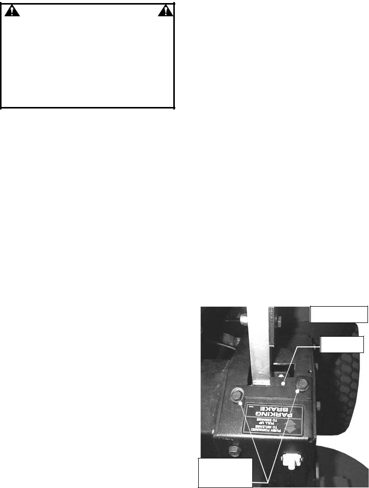
STEP 14: TRACKING ADJUSTMENT – TWIN STICK CONTROLS
Start machine. If the machine does not track straight when the Motion Control Levers are in the maximum forward speed position, perform the following adjustment. Rear tire pressure must be set to 12 PSI before making this adjustment.
A.Loosen bolts that secure adjustment plates and slide plates all the way forward. Retighten bolts.
B.Start machine and drive in smooth flat open area at maximum forward speed.
C.If machine tracks to the right, loosen bolts that secure the left adjustment plate. Move plate rearward to slow the left wheel. Retighten bolts.
D.If machine tracks to the left, loosen bolts that secure the right adjustment plate. Move plate rearward to slow the right wheel down. Retighten bolts. See Figure 2.
E.Drive machine again. Repeat adjustment as necessary until machine tracks straight.
 LEFT SIDE MOTION
CONTROL LEVER
ADJUSTMENT
PLATE
LOOSEN BOLTS.
SLIDE PLATE TO
MAKE MACHINE
TRACK STRAIGHT
FIGURE 2
2
 Loading...