

Page 1
SET-UP INSTRUCTIONS & PRE-OPERATION CHECKLIST
SNAPPER ZERO TURNING Z-RIDER with MID MOUNT MOWER
INTRODUCTION: These instructions cover the set-up of the Snapper M id Mount Z-Rider M ower. Complete each
of the following st eps carefully. Review and complete each item as instruct ed on the Pre-Operation checklist.
The Snapper Product Registration card must be filled out and sent to Customer Service department at Snapper
when completed.
IMPORTANT: The battery for this unit is shipped dry. A package of battery acid (electrolyte) will have to be
purchased separately. Allow sufficient time for charging and installing the battery before operating the rider.
Pay close attention to the precautionary statements on the battery and in these instructions. You will also need
an automotive type battery charger to activate the battery for use.
STEP 1: Remove machine from the container. The
battery will have to be charged and installed.
STEP 2: Remove battery from the battery compartment
before charging.
STEP 3: Place battery in a well ventilated area on a
level non-concrete surface.
WARNING
The electrolyte (acid) produces a h ighly explosive gas.
Keep all sparks, flame and fire away from area when
charging battery or when handling electrolyte or
battery. Electrolyte (acid) is a highly corrosive liquid.
Wear eye protection. Wash affected areas immediately
after having eye o r skin contact with electrolyte ( acid).
Battery acid is corrosive. Rinse empty acid containers
with water and mutilate before discarding. If acid is
spilled on battery, bench, or clothing, etc., Flush with
clear water and neutralize with baking soda.
STEP 4: Remove batter y cell caps. Fill cells as required
with electrolyte (purchased separately) to proper level.
Filling battery with electrolyte will bring the battery to
80% charged state.
WARNING
DO NOT OVERFILL!
STEP 5: With cell caps removed, connect battery
charger to battery terminals; RED to positive (+) and
BLACK to negative (-) terminal.
STEP 6: Slow charge the battery at 2 amp f or 2 hours
to bring the battery to full charge.
STEP 7: After charging, check level of electrolyte and
add as needed to bring fluid to proper level.
STEP 8: Reinstall cell caps.
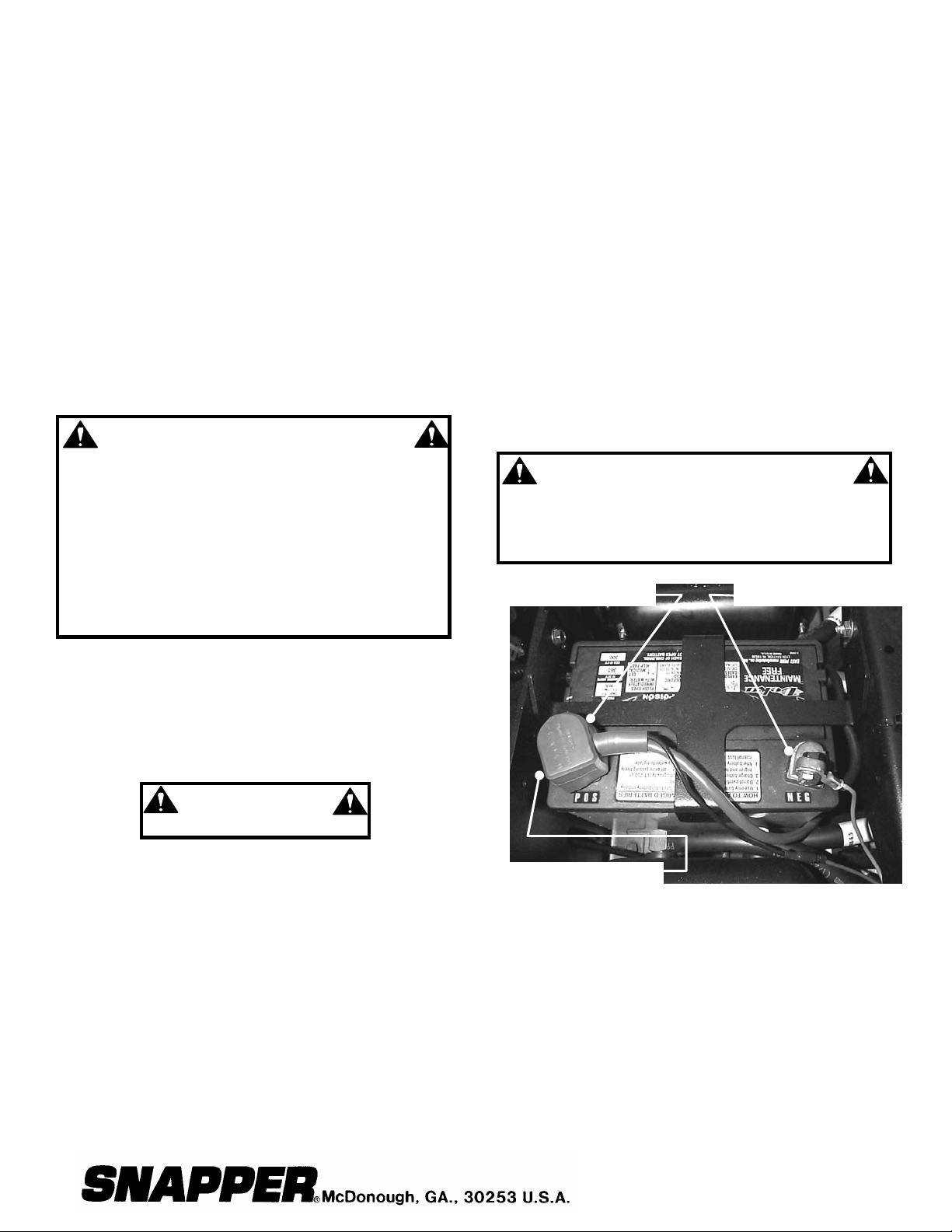
STEP 9: Install battery into power unit.
STEP 10: Both bolts are already installed on both
terminals. Connect positive (+) cable (red) first, from
wiring harness to the positive terminal (+) on battery and
secure with nut provided in hardware bag. Connect
negative (-) cable (black) last, to negative ter minal (-) on
battery and secure with nut also provided. Apply a small
amount of grease over terminals to prevent corrosion.
See Figure 1.
WARNING
Shield the positive terminal with terminal cover
located on battery harness. This prevents metal
from touching the positive terminal, which could
cause sparks.
RED (POSITIVE) CABLE
TERMINAL COVER MUST
SHIELD POSITIVE
TERMINAL AFTER
INSTALLATION
FIGURE 1
STEP 11: Take the necessary precautions, when
handling fuel. Fill the f uel tank with clean fuel. Chec k oil
and add oil if needed as stated in Engine Owners
Manual. Move fuel tank selector valve handle to the
desired fuel tank.
INSTRUCTION No. 7-5597 (I.R. 4/1/03)
1
BLACK (NEGATIVE) CABLE
Page 2
WARNING
PLATE
CONTROL LEVER
Handle fuel with care! Use an approved fuel
container. DO NOT smoke near open fuel container
and keep fuel container away from open flame. DO
NOT fill fuel tank indoors or when engine is
running. Allow engine to cool for at least ten
minutes before refilling. Wipe off any spilled fuel
before starting engine. DO NOT run engine indoors.
Before attempting any adjustments, maintenance,
service, or repairs, stop engine and blade, always
remove key from ignition sw itch , remov e spark p lug
wire(s) and secure wire(s) away from spark plug(s).
STEP 12: MOWER DECK ADJUSTMENT (LEVELNESS)
SIDE to SIDE and FRONT to REAR
Before mak ing deck leveling adjus tments, inflate r ear tires
to 12 PSI and front tires to 25 PSI. When adjusted
correctly, the deck will be level side to side within 1/8”, have
a low cut setting of approximately 1” and the blades pitched
approximately 3/16” higher at the rear.
A. Place machine on a smooth level surface.
B. Check blade tips by rotating blades until tips are
pointing to the sides of the deck. Check the
measurement of outside blade tips to the ground on
both blades. The measurem ent of each of the outside
blade tips should be within 1/8” of each other. If
measurement of the blade tips is not within 1/8”,
adjustment should be made to the correct
measurement.
C. Move deck lift lever and set the mower deck to the
highest cutting position.
D. Relieve tension on deck lift assist spring by loosening
nut on eyebolt.
E. Place 1” blocks under the f ront and rear edge of the
mower deck.
F. Move deck lift lever and set the mower deck to a
lower cutting position until deck rests on the 1” blocks.
G. Loosen the nuts and bolts that secure both front
deck support chains. Adjust chains until tight and
retighten bolts and nuts. Torque to 70 ft. lbs.
H. Loosen the nuts that secure both rear deck support
eyebolts. Adjust to remove slack from both rear chains.
Tighten nuts securely.
I. Move deck lift lever and set the mower deck to the
highest cutting position and recheck side to side blade
tip dimensions. The dif ference between the two should
be 1/8” or less.
NOTE: The deck tim ing rod is preset at the factor y and
requires no adjustments.
J. The leveling blocks used in Step E should result in a
proper deck pitc h. If a pitc h adjustm ent is required, us e
the two rear deck support eyebolts. Adjust up or down
as required.
K. Reinstall deck lif t ass ist spr ing. Place deck in highest
cutting position. Tighten nut on eyebolt until 1 1/4” of
threads protrude past end of nut.
STEP 13: HYDRAULIC OIL RESERVOIRS
Check the level of the fluid in both of the fluid reservoirs. The
reservoirs are loc ated underneath the operator’s s eat. W ipe
away all dirt and debris from around reservoir cap before
removing. Oil must remain absolutely clean! Check with
machine on a level surf ace with engine “OFF”. Fill res ervoir
as needed to bring level up. The res ervoir is properly filled
when the fluid level is 1½” below the top of the filler neck. DO
NOT OVER FILL. Use clean, fresh prem ium automotive oil
having a viscosity equivalent to SAE 20W50 API SL. The
fluid should be chemically stable, incorporating rust and
oxidation inhibitors. Make sure funnels, pouring spouts and
oil can are completely clean. Reinstall reservoir cap.
IMPORTANT: Re-check fluid level after operating machine for
several minutes and adjust level as needed. If one or both of
the wheel drive systems is not pulling properly, the hydraulic
system may need to be purged of entrapped air. Refer to
STEP “HYDRAULIC SYSTEM, PURGING”.
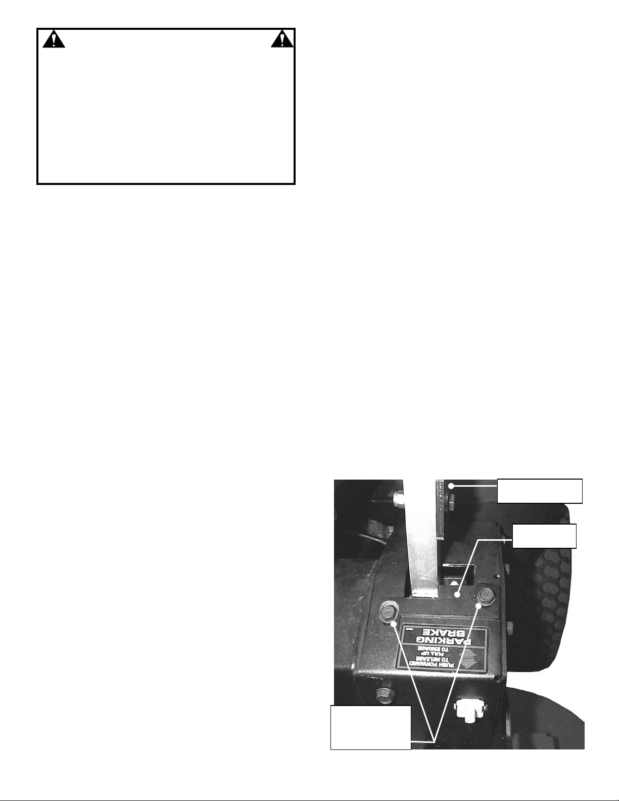
STEP 14: TRACKING ADJUSTMENT – TWIN STICK
CONTROLS
Start machine. If the m achine does not track straight when
the Motion Control Levers are in the maximum forward
speed position, perform the f ollowing adj ustment. Rear tire
pressure must be set to 12 PSI before making this
adjustment.
A. Loosen bolts that secure adjustment plates and slide
plates all the way forward. Retighten bolts.
B. Start machine and drive in smooth flat open area at
maximum forward speed.
C. If machine tracks to the right, loosen bolts that secure the
left adjustment plate. Move plate rear ward to slow the left
wheel. Retighten bolts.
D. If machine tracks to the left, loosen bolts that sec ure the
right adjustment plate. Move plate rearward to slow the
right wheel down. Retighten bolts. See Figure 2.
E. Drive machine again. Repeat adjustm ent as necessary
until machine tracks straight.
LEFT SIDE MOTION
ADJUSTMENT
LOOSEN BOLTS.
SLIDE PLATE TO
MAKE MACHINE
TRACK STRAIGHT
FIGURE 2
2
Page 3

STEP 15: HYDRAULIC SYSTEM, PURGING
After replacing or repairing hydraulic system
components, one or both of the wheel drives may
not pull properly. This is likely to be caused by air
entrapped in the system. If you experience a
pulling issue after completing repairs or during
initial setup, perform the following procedure to
purge the air from one or both of the hydraulic
drive systems.
IMPORTANT: WHEN REPLACING THE HYDRAULIC
FLUID FILTERS, PRE-FILL BOTH WITH OIL
(SAE 20W50 AP I SL) BEFORE INSTALLING.
PRE-FILLING THE FILTERS WITH OIL WILL
REDUCE OR POSSIBLY ELIMINATE THE NEED
TO PURGE THE SYSTEM OF ENTRAPPED AIR.
A. Locate hydraulic reservoir underneath
operator’s seat. After thoroughly cleaning the area
around the top of the reservoir, remove filler cap.
Bring fluid to proper level (1 ½” below the top of
the filler neck). With engine off, add SAE 20W50
automotive oil. See Figure 3.
B. Open pressure relief valve on hydraulic pump,
turning counter clockwise 2 full turns. See Figure
4.
C. Carefully raise the rear of the machine so the
wheels are off of the ground. Securely block the
machine to prevent it from falling.
D. While seated in the operator’s position, start the
engine. Place engine speed control in FAST
position.
E. Release parking brake and move motion
control levers out of the neutral lock position.
F. Slowly move motion control levers to the full
forward and then to the full reward positions.
Repeat this process 6 times.
G. Stop engine and wait for all rotation to stop
before leaving the operator’s position.
H. Close pressure relief valve on hydraulic pump,
turning clockwise. Tighten snuggly.
I. With pressure relief valve closed, repeat Steps
4 thru 7.
J. Remove blocks and lower rear of machine.
K. Check fluid level in reservoir. Add SAE 20W50
automotive oil as required to bring fluid level to 1
½” from top of filler neck. Do Not over fill.
L. Install and tighten filler cap.
HYDRAULIC
RESERVOIRS
FIGURE 3
ROTATE RELIEF VALVE
COUNTERCLOCKWISE
TO RELIEVE PRESSURE
RELIEF VALVE
FIGURE 4
3
Page 4

PRE-OPERATION CHECKLIST
Snapper has completed initial adjustments and performed operational tests prior to shipping the machine. Due
to the possible effects of shipping, handling and storage, Snapper intends for all of the following items to be
verified and necessary final adjustments made at time of setup. It remains good practice and is strongly
recommended that all the items also be checked prior to placing the machine into service. It is very important
that setup is verified and all o perational t ests complet ed and result s are acceptable. After completing t his form,
sign and retain for future reference.
CUTTING BLADE & MOWER
__ BLADE RETAINING hardware checked for proper tightness.
__ MOWER CUTTING HEIGHT settings checked and adjusted as needed (with tires properly inflated).
__ MOWER SIDE TO SIDE level checked and adjusted as needed (with tires properly inflated).
__ MOWER FRONT TO REAR setting checked and adjusted as needed (with tires properly inflated).
PRE-START CHECKS & SERVICES
__ TIRES checked and inflated to correct pressures.
__ ENGINE OIL level checked. See Engine Owners Manual.
__ FUEL added to tank and system checked for leaks.
__ BATTERY (Not overfilled!) reinstalled and properly connected with red boot over positive terminal.
__ HYDRAULIC FLUID level checked.
OPERATIONAL TESTS
__ CHECK SEAT SWITCH for proper function.
__ INTERLOCK SYSTEMS checked to insure proper functioning.
__ ENGINE STARTED and throttle control settings checked.
__ ALL OPERATIONS as listed on console checked.
__ IGNITION SWITCH checked to insure engine stops when turned to OFF position.
__ PARKING BRAKE tested to insure proper operation.
__ BLADE ENGAGEMENT SWITCH tested for engagement and disengagement of blade.
__ BLADE BRAKE function verified. Blade rotation stops in 7 seconds or less.
__ MACHINE TRACKING tested and adjusted as required.
DEMONSTRATION & INSTRUCTION
__ DEMONSTRATED proper operation of mower to purchaser.
__ INSTRUCTED purchaser to read and follow instructions in Operator's Manual.
__ PERSONALLY HANDED Operator's Manual to purchaser.
__ ASSISTED purchaser in completing Product Registration cards.
DEALER'S RECORDS
Sale Date
Dealer's Name
Address_________________________ City
Will Mower be used Commercially? Yes ______________ No
Purchaser's Name
Address______________________________ City
IMPORTANT: This form is to be retained by the dealer for future reference regarding Warranty, proof of
purchase, traceability for product recall or service, etc. Complete the Product Registration Card and Mail to
Customer Service Department at SNAPPER, PO BOX 1379, McDonough, Georgia, 30253.
COPYRIGHT © 2003
SNAPPER PRODUCTS INC.
ALL RIGHTS RESERVED
Model Serial No.
Signature
State Zip
Signature
State Zip
INSTRUCTION No. 7-5597 (I.R. 4/1/03)
4
 Loading...