

Page 1
DEALER SET-UP INSTRUCTIONS & CHECKLIST For
SNAPPER REAR ENGINE RIDERS
Tools required for set-up are: HAMMER, PLIERS,
7/16” and 1/2” WRENCH or SOCKET.
A package of Battery Acid (Electrolyte), purchased
separately, is required for electric start models.
SNAPPER Rear Engine Riding Mowers are shipped with
steering components, seat & fuel tank detached. After
uncrating, inspect the machine for damage, then
proceed as follows to assemble and prepare the unit.
Open parts box and hardware bag and identify
components shown on pages 5, 6, & 7. NOTE that NOT
ALL PARTS in each bag are used on any one rider.
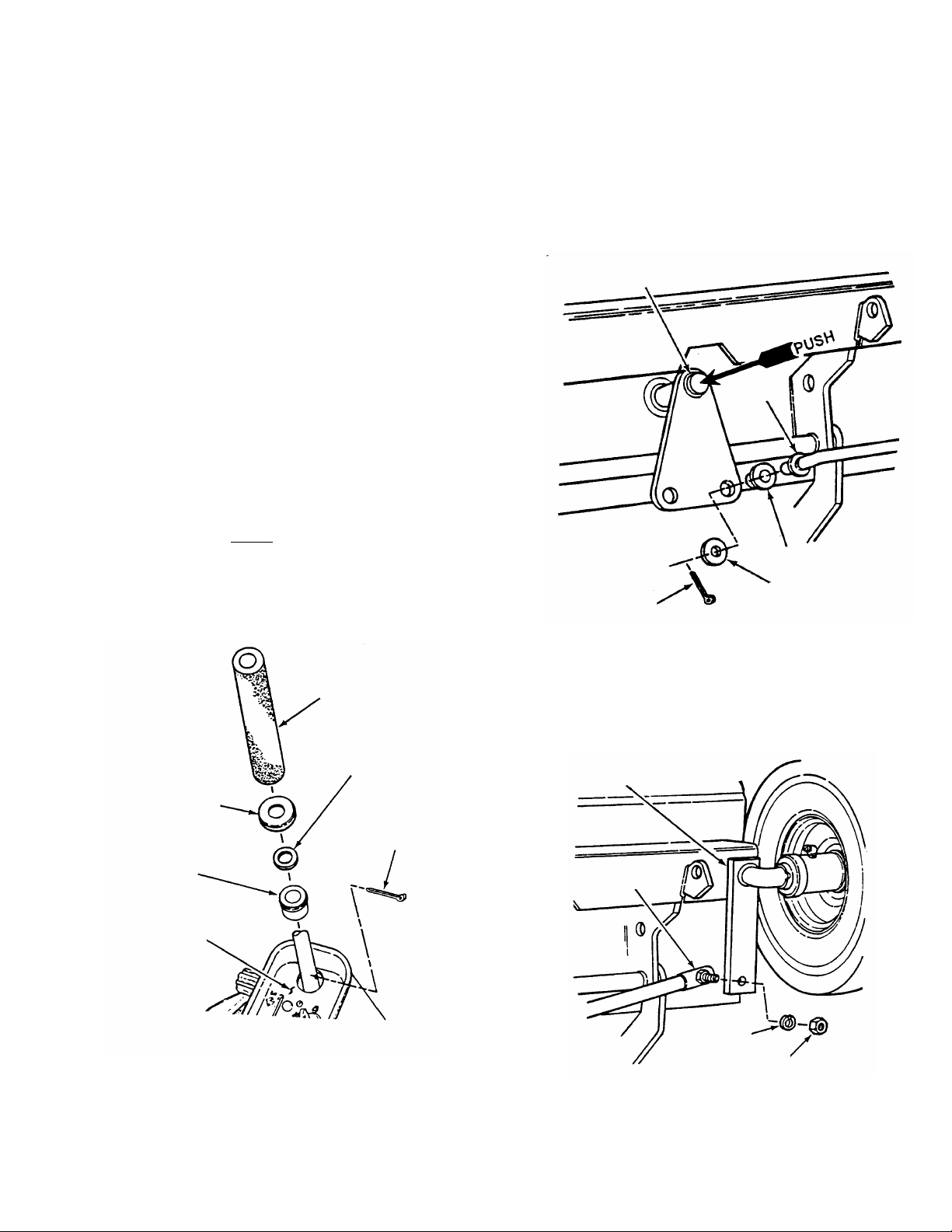
A. STEERING COMPONENTS
1. Steering Shaft
(a) Carefully stand Rider on rear bumper.
(b) Push steering shaft into place (See figure 2).
(c) Remove/discard vinyl cap from steering shaft
end.
(d) Tap upper bushing so that it contacts control
panel.
(e) Place thrust washer on top of bushing.
(f) Install 3/16” x 1-1/2” cotter-pin f rom parts bag
into steering shaft above
(g) Install bushing cover over cotter-pin, thrust
washer and bushing.
(h) Slide foam steering shaft cover over steering
shaft. See Figure 1.
thrust washer.
2. Installing Tie Rods - Narrow Front Frame (28”
& smaller deck)
(a) Install bushings onto tie rods.
(b) Install tie rods into steer ing shaft. Secure with
3/8” flat washers and 5/32” x 1” cotter-pins. See
Figure 2.
STEERING
SHAFT
TIE
ROD
BUSHING
5/32” X 1”
COTTER PIN
3/8” FLAT
WASHER
BUSHING COVER
(CUP DOWN TO
COVER COTTER
PIN)
UPPER
BUSHING
CONTROL
PANEL
FIGURE 1
FOAM STEERING
SHAFT COVER
THRUST
WASHER
3/16” X 1-1/2”
COTTER PIN
FIGURE 2
3. Installing Tie Rods - Wide Front Frame (30” &
larger deck)
(a) Install tie rods, 5/16” lock washers and 5/16”-
24 hex nuts. Tighten securely. See Figure 3.
STEERING
ARM
TIE ROD
5/16” SPLIT
LOCKWASHER
5/16” HEX NUT
FIGURE 3
INSTRUCTION No. 3-5621 (REV. 3, 8/20/99)
Page 2
4. Installing Steering Wheel
(a) Slide steering wheel on steering shaft.
Normally, the offset of the steering wheel should
be towards operator’s seat.
NOTE
: For more operator room, the steering wheel
offset can be turned towards front of the Rear Engine
Rider. The “SNAPPER” logo in the center of steering
wheel can be snapped out and turned also.
(b) Support steering wheel and drive the 1/4” x 1-
1/2” roll pin into steering wheel and steering shaft.
See Figure 4.
SUPPORT STEERING WHEEL
WHILE DRIVI NG ROL L PIN
STEERING
WHEEL WITH
OFFSET
TOWARDS
OPERATOR’S
SEAT
1/4” X 1-1/2”
ROLL PIN
FIGURE 4
B. MOWING DECK
1. Cutting Blade
(a) Check the torque of mowing blade(s)
mounting bolt(s). (30 to 40 f t. lbs. recomm ended
for single blade mowers & 40 to 50 ft. lbs.
recommended for double blade mowers).
(b) Check blade(s) straightnes s per operators
manual.
C. LUBRICATION
1. Perform norm al lubrication of the Rear Engine
Rider. Check dif ferential and chain c ase for pr oper
lubricant levels. See
Operator’s manual.
2. After completing lubrication, carefully lower
Rear Engine Rider to floor to continue set-up.
D. FUEL SYSTEM
1. Fuel Tank
Place fuel tank in brack et behind seat bracket
and push tank down until it snaps into position.
See Figure 5.
PUSH
FUEL
TANK
HOSE
CLAMPS
FUEL
LINE
FUEL
FILTER
FIGURE 6
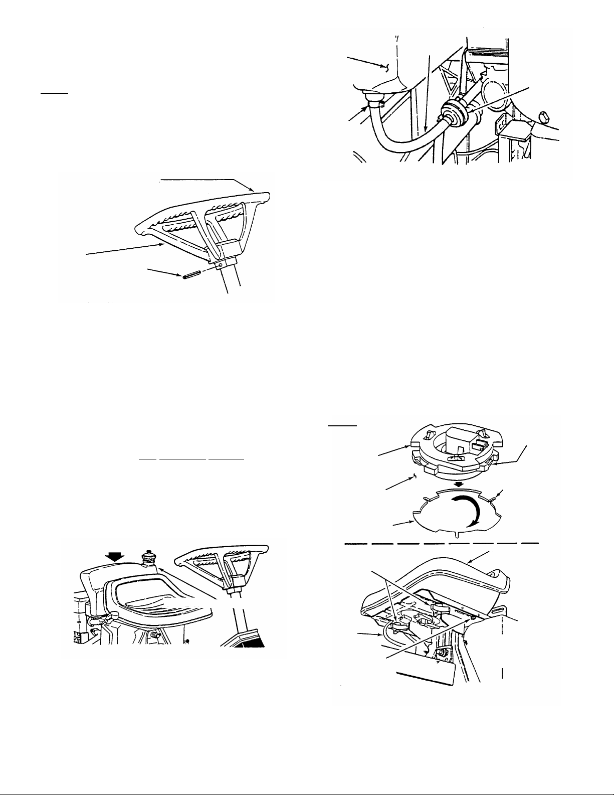
E. OPERATOR’S SEAT – NON-HINGED MODELS
1. Install seat switch into bottom of seat by
pushing in and turning clockwise until switch locks
into place. See Inset in Figure 7.
2. Lay forward edge of seat onto seat pan with seat
switch protruding through opening in pedestal.
3. Connect seat switch wiring harness to male
tabs of seat switch (under seat). See Figure 7.
4. Position operator’s seat onto seat bracket.
5. Install two 5/16-18 hex head flange patch lock
screws into rear holes of seat.
6. Install two spacers onto the two adjusting knobs.
7. Install adjusting knobs through seat bracket
and into the two front holes in operator’s seat.
8. Adjus t seat to des ired position. Par tially tighten
rear screws, allowing seat to slide front to back.
Tighten adjusting k nobs to secur e seat in position.
See Figure 7.
INSET
TAB
SEAT
SWITCH
P.N. 2-9211
BOTTOM OF
OPERATOR’S
SEAT
SWITCH
MOUNTING
HOLE
ADJUSTING
KNOBS &
SPACERS
INSERT SWITCH &
ROTATE 1/8” OF A
TURN CLOCKWISE
LOCKS
TAB LOCK
ENGAGEMENT
SLOTS
OPERATOR’S
SEAT
FUEL TANK ORIENTATION
SEAT
SWITCH
WIRE
FIGURE 5
2. Fuel Line
Slide fuel line onto fuel tank hose barb and
move hose clamp above end of the fuel tank
hose barb (approximately 1/8” from end of
hose). The fuel f ilter has been installed by the
engine manufacturer. See Figure 6.
5/16-18 PATCH
LOCK SCREW
(DO NOT
OVERTIGHTEN!)
FIGURE 7
2
Page 3

E. OPERATOR’S SEAT – HINGED SEAT MODELS
OF SEAT
1. Fold the hinged seat plate forward and follow
steps 4 through 8 in Section “OPERATOR’S
SEAT, NON-HINGED MODELS” for 8 & 10HP
models. See Figure 8.
5/16” PATCH LOCK
SCREWS
ADJUSTING
KNOBS &
SPACERS
FRONT
FIGURE 8
F. BATTERY
The batteries for the electric start models are
shipped dry. It should be activated and charged
according to the instructions below.
1. BATTERY REMOVAL
(a) Remove battery cover by pulling each side
away from ratchet fasteners. See Figure 9.
PULL COVER AWAY FROM
RATCHET FASTENERS ON
BOTH SIDES
FIGURE 9
(b) Remove the hair pin and swivel from the
deck support to allow clearance for battery
removal.
(c) Remove battery from battery compartment.
2. BATTERY ACTIVATION
(a) Place battery in a well ventilated area on a
level surface.
(b) Remove battery cell caps. Fill cells as
required with electrolyte to between minimum
and maxim um fill line as viewed from outside
battery case. Filling battery with electrolyte will
bring the battery to 80% charged state.
WARNING
The electrolyte (acid) produces a highly explosive
gas. Keep all sparks, flame and fire away from area
when charging battery or when handling electrolyte
or battery. Electrolyte (acid) is a highly corrosive
liquid. Wear eye protection. Wash affected areas
immediately after having eye or skin contact with
electrolyte (acid). Battery acid is corrosive. Rinse
empty acid containers with water and mutilate
before discarding. If acid is spilled on battery,
bench, or clothing, etc., Flush with clear water and
neutralize with baking soda. DO NOT attempt to
charge battery while installed on the RIDER. DO
NOT use “BO OST” charg ers on th e battery. DO NOT
OVER FILL!
NOTE:
above cell plates. DO NOT
other than specified electrolyte.
The rec omm ended level of elec trolyte is 3/16”
place anything in battery
3. BATTERY CHARGING
(a) With all cell caps removed, connect an
automotive type battery charger to battery
terminals; RED to positive (+) and BLACK to
negative (-) terminal.
(b) Slow charge at 2 to 6 amps for 30 minutes.
(c) A f t er c ha rg in g, c he c k le ve l o f el ec t ro lyte , add
electrolyte if necessary, and tighten cell caps.
3
Page 4

4. BATTERY INSTALLATION
SHOWN
(a) Slide battery partially into box, with positive
end to inside and terminals to rear, to allow for
cable installations.
(b) Battery cables MUST BE SECURED TO
BATTERY TERMINALS as s hown in Figure 10,
using the 1/4” screws, that are mounted on
terminals, and lock nuts from the hardware bag.
(c) Install positive (+) cable first. Place the
positive (+) terminal insulator over positive
terminal and cable. Install negative (-) cable last
positive terminal insulator has been
after
installed. See Figure 10.
(d) Slide battery into battery box and reinstall
battery cover.
(e) Reinstall deck support swivel and hair pin.
H. ELECTRICAL CIRCUIT
The electrical connection at the engine is shipped
disconnected to protect the electrical s ystem when
the battery is installed and MUST BE THE LAST
STEP in preparation.
1. Connect electrical circuit at rear of the engine.
See Figure 12.
WARNING
IF ENGINE ELECTRICAL COMPONENTS
ARE CONNECTED WITHOUT THE BATTERY
PROPERLY INSTALLED AND ENGINE IS
STARTED, THE POSITIVE (+) CABLE COULD
ARC CAUSING DAMAGE OR INJURY.
CABLES MUST BE
MOUNTED TO
TERMINALS AS
BLACK
NEGATIVE (-)
CABLE
RED POSITIVE (+) CABLE
TO OUTSIDE OF
MOWER
FIGURE 10
G. DISCHARGE DEFLECTOR
The discharge deflector is shipped in the “UP”
position. Remove rubber band, lower discharge
deflector and secure to deck with carriage bolt(s), flat
washer(s) and wing nut(s) furnished in the dec k. See
Figure 11.
SECURE DISCHARGE
DEFLECTOR TO DECK
WITH CARRIAGE BOLTS,
FLAT WASHERS, & WING
NUTS
FIGURE 11
POSITIVE
TERMINAL
INSULATOR
FIGURE 12
I. ENGINE
Perform engine ser vice, oil and fuel, according to
engine manufacturer’s recommendations.
J. PRE-SALE CHECK
Completely fill out the attached Pre-Sale Check list
BEFORE starting the engine, testing the Rear
Engine Rider or delivering to the customer.
4
Page 5

SERVICE NOTES
______________________________________________________________________________
______________________________________________________________________________
______________________________________________________________________________
______________________________________________________________________________
______________________________________________________________________________
______________________________________________________________________________
______________________________________________________________________________
______________________________________________________________________________
______________________________________________________________________________
______________________________________________________________________________
______________________________________________________________________________
______________________________________________________________________________
______________________________________________________________________________
______________________________________________________________________________
______________________________________________________________________________
______________________________________________________________________________
______________________________________________________________________________
______________________________________________________________________________
______________________________________________________________________________
______________________________________________________________________________
______________________________________________________________________________
______________________________________________________________________________
______________________________________________________________________________
______________________________________________________________________________
______________________________________________________________________________
______________________________________________________________________________
______________________________________________________________________________
______________________________________________________________________________
______________________________________________________________________________
______________________________________________________________________________
______________________________________________________________________________
______________________________________________________________________________
______________________________________________________________________________
______________________________________________________________________________
______________________________________________________________________________
______________________________________________________________________________
______________________________________________________________________________
______________________________________________________________________________
______________________________________________________________________________
______________________________________________________________________________
______________________________________________________________________________
______________________________________________________________________________
______________________________________________________________________________
______________________________________________________________________________
______________________________________________________________________________
______________________________________________________________________________
______________________________________________________________________________
______________________________________________________________________________
______________________________________________________________________________
______________________________________________________________________________
5
Page 6

DEALER PRE-SALE CHECKLIST
The following must be accomplished prior sale. Refer to detailed set-up instructions. Review this list with
purchaser. Check (
✓) items actually performed and signed on this page.
SET-UP CHECKLIST
______ STEERING WHEEL and steering shaft assembled.
______ TIE RODS connected.
______ LUBRICATION of entire unit completed.
______ OPERATOR’S SEAT installed and tightened and seat switch connected.
______ FUEL TANK installed and fuel line connected.
______ GRASS DEFLECTOR, MULCH COVER or CATCHER ADAPTER and assembly positioned, secured, checked.
______ BATTERY activated and charge per instructions and installed into battery compartment on rider.
______ TIRE inflated to proper Pounds per Square Inch (PSI). Front tire is 15 PSI and Rear tire is 10 PSI.
CUTTING BLADE & MOWER
______ BLADE RETAINING hardware checked for proper tightness.
______ BLADE TIP CLEARANCE inside lower edge of mower checked and corrected as needed.
______ BLADE STRAIGHTNESS checked and adjusted as required.
______ MOWER CUTTING HEIGHT settings checked and adjusted as needed (with tires properly inflated).
______ MOWER SIDE TO SIDE level checked and adjusted as needed (with tires properly inflated).
______ MOWER FRONT TO REAR setting checked and adjusted as needed (with tires properly inflated).
______ BLADE LEVER checked and adjusted as required.
______ BELT TENSION checked and adjusted as required. (25” Decks Only)
PRE-START CHECKS & SERVICES
______ TIRES checked and inflated to correct pressures.
______ ENGINE OIL level checked.
______ DIFFERENTIAL check lubricant and add as needed.
______ CHAIN CASE check lubricant and add as needed.
______ YOKE ASSEMBLY checked for freedom of movement.
______ FUEL added to tank and system checked for leaks. Refer to Engine’s Owner’s Manual for fuel specifications.
______ BATTERY (not overfilled!) reinstalled and properly connected with red boot over positive terminal.
OPERATIONAL TESTS
______ CHECK SEAT SWITCH for proper function
______ INTERLOCK SYSTEMS checked to insure proper functioning.
______ ENGINE STARTED and throttle control settings checked.
______ IGNITION SWITCH checked to insure engine stops when turned to OFF position.
______ PARKING BRAKE tested to insure proper operation.
______ CLUTCH/BRAKE tested for proper operation and adjusted as required.
______ BLADE STOPS in 3 seconds or less after releasing the blade pedal. Adjust blade brake as required.
______ BLADE LEVER can be moved to “OFF” position with blade pedal depressed.
DEMONSTRATION & INSTRUCTION
______ DEMONSTRATED proper operation of mower to purchaser.
______ INSTRUCTED purchaser to read and follow instructions in Operator's Manual.
______ PERSONALLY HANDED Operator's Manual, Engine Manual, and “USER and SAFETY GUIDE” video to purchaser.
______ ASSISTED purchaser in completing Product Registration cards.
DEALER'S RECORDS
SALE DATE RIDER MODEL SERIAL NO.
Dealer's Name
Address_________________________ City
TRACTOR WILL BE USED COMMERCIALLY? YES _________ NO
Purchaser's Name
Address_________________________ City
Signature
State Zip
Signature
State Zip
IMPORTANT: This form is to be retained by the Dealer for future reference regarding Warranty, proof of purchase,
traceability for product recall or service, etc. Complete the Product Registration Card immediately and mail to: Customer
Service Department at SNAPPER, P.O. BOX 1379, McDonough, Georgia, 30253.
INSTRUCTION No. 3-5621 (REV. 3, 8/20/99)
6
 Loading...