

Page 1

Safety Instructions & Operator’s Manual for
20” STEEL DECK
WALK MOWERS
SERIES 13
MODEL
R204513E
MODEL NUMBER EXPLANATION
R 20 45 13 E
MODEL DESIGNATION ENGINE OPTIONS
CUTTING WIDTH SERIES DESIGNATION
ENGINE HORSE POWER
R – Recycling Model 13 - Series Designation
20 – 20” Cutting Width E – Electric Start Model
45 – 4.5 HP (Engine Horse Power)
Thank you for buying a SNAPPER Product! Before operating your Walk Behind, read this manual carefully and pay
particular attention to the “IMPORTANT SAFETY INSTRUCTIONS” on Pages 2 & 3. Remember that all power
equipment can be dangerous if used improperly. Also keep in mind that SAFETY requires careful use in accordance
with the operating instructions and common sense.
COPYRIGHT © 1999
SNAPPER INC.
ALL RIGHTS RESERVED
MANUAL No. 7-2036 .(REV. 1, 5/17/99)
Page 2

IMPORTANT SAFETY INSTRUCTIONS
WARNING: This powerf ul cutting machine is capab le of amputating hand s and feet and can throw objects that
can cause injury and damage! Failure to comply with the follow ing SAFETY instru ctions could resu lt in serious
injury or death to the operator or other persons. The owner of the machine must understand these instructions
and must allow only persons who understand these instructions to operate machine. Each person operating the
machine must be of sound mind and body and must not be under the influence of any substance, which might
impair vision, dexterity or judgment. If you have any questions pertaining to your machine which your dealer
cannot answer to your satisfaction, call or write the Customer Service Department at SNAPPER, McDonough,
Georgia 30253. Phone: (1-800-935-2967).
PROTECTION FOR CHILDREN
Tragic accidents can occur if the operator is not
alert to the presence of children. Ch ildren are often
attracted to the machine and the mowing activity.
Never assume that children will remain where you
last saw them.
1. KEEP children out of the mowing area and
under the watchful care of a responsible adult.
2. DO NOT allow children in yard when mach ine is
operated and turn machine OFF if anyone
enters the area.
3. DO NOT allow pre-teenage children to operate
machine.
4. ALLOW only responsible adults & teenagers
with mature judgment under close adult
supervision to operate machine.
5. DO NOT pull mower backwards unless
absolutely necessary. LOOK BEHIND and dow n
for small children before and when backing.
6. USE EXTRA CARE when approaching blind
corners, shrubs, trees, or other object s that may
obscure vision.
SLOPE OPERATION
1. Slopes are a major factor related to slip and fall
accidents, which can result in severe injury. All
slopes require extra cau tion. If you feel uneasy
on a slope, do not mow it.
2. Mow across slopes, never up-and-down.
Exercise extreme CAUTION when changing
directions on slopes. DO NOT mow steep
slopes or other areas where stability or traction
is in doubt.
PREPARATION
1. Read, understand, and follow instructions and
warnings in this manual and on the mower and
with attachments. Know the controls and the
proper use of the mower before starting.
2. Only mature, responsible persons shall operate
the machine and only after proper instruction.
3. Data indicates that o perators age 60 and abov e,
are involved in a large percentage of mowerrelated injuries. These operators should
evaluate their ability to operate the mower
safely enough to protect themselves and others
from serious injury.
PREPARATION
4. Handle fuel wit h ext ra care. Fuels are flammab le
and vapors are explosive. Use only an approved
fuel container. Never remove fuel cap or add
fuel with engine running. Add fuel outdoors
only with engine stopped and cool. Clean
spilled fuel and oil from machine. DO NOT
smoke. DO NOT run engine indoors.
5. Check the area to be mowed and remove all
objects such as toys, wire, rocks, limbs and
other objects that could cause injury if thrown
by blade or interfere with mo win g. Also note the
location of holes, stumps, and other possible
hazards.
6. Keep people and pets a safe distance from
machine.
7. Check shields, deflectors, switches, blade
controls and other safety dev ices frequently for
proper operation and location.
8. Make sure all safety decals are clearly legible.
Replace if damaged.
9. Protect yourself when mowing and wear safety
glasses, long pants and substantial footwear.
DO NOT mow barefooted or with sandals.
10. Know how to STOP blade and engine quickly in
preparation for emergencies.
11. Use extra care when loading or unloading the
machine into a trailer or truck.
OPERATION
1. DO NOT put hands or feet near or under rotating
parts. Keep clear of discharge area wh ile engine
is running.
2. STOP engine when crossing gravel drives,
walks, or roads, and under any conditions
where thrown objects might be a hazard.
3. Mow only in daylight or good artificial light.
4. DO NOT operate mower while under the
influence of alcohol or drugs.
5. After striking a foreign object or if mower
vibrates abnormally, STOP the engine,
disconnect and secu re spark plug wire. Inspect
the mower for any damage and repair the
damage.
2
Page 3

IMPORTANT SAFETY INSTRUCTIONS
OPERATION
6. Watch for holes, rut s or bumps. Tall grass can
hide obstacles.
7. DO NOT mow near drop offs, ditches or
embankments. Operator could lose footing or
balance.
8. DO NOT mow on wet grass Always be sure of
your footing; keep a firm hold on the handle and
walk; never run. Slipping could cause injury.
STOP blade and engine w henever you leav e the
operating position behind the handle for any
reason, including clearing grass, emptying
grass bag and making wheel height
adjustments, repairs, or inspections.
9. Before cleaning, repairing or inspecting make
certain blade and all moving parts have
STOPPED. Disconnect and secure spark plug
wire away from plug to prevent accidental
starting.
10. STOP engine and wait u ntil the blade comes to
complete STOP before removing grass bag
and/or clearing grass.
MAINTENANCE AND STORAGE
1. Never store machine or fuel container inside
where fumes may reach an open flame, spark or
pilot light such as in a water heater, furnace,
clothes dryer or other gas appliance. Allow
engine to cool before storing machine in an
enclosure. Store fuel container out of reach of
children in a well ventilated, unoccupied
building.
2. Keep mower and engine free of grass, leaves or
excess grease to reduce fire hazard and engine
overheating.
3. When draining fuel tank, drain fuel into an
approved container outdoors and away from
open flame.
MAINTENANCE AND STORAGE
4. Keep all bolts, especially blade bolts, n uts and
screws properly tight. Check that all cott er pins
are in proper position.
5. Service engine and make adjustments only
when engine is stopped. Removed spark plug
wire from spark p lu g an d secu re w ire away from
spark plug to prevent accidental starting.
6. DO NOT change engine governor speed
settings or overspeed engine.
7. Check grass bag assembly frequently for wear
or deterioration to avoid thrown objects and
exposure to moving parts. Replace with new
bag if loose seams or tears are ev ident. Rep lace
slider or bag adapter if broken or cracked.
8. Mow er blades are sharp and can cut. Wrap the
blades or wear heavy leather gloves and use
CAUTION when handling them.
9. NEVER test for spark by grounding spark plug
next to spark plug hole; spark plug could ignite
gas exiting engine.
10. Have machine serviced by an authorized
SNAPPER dealer at least once a year and have
the dealer install any new safety devices.
11. Use only genuine SNAPPER replacement parts
to assure that original standards are
maintained.
3
Page 4

TABLE OF CONTENTS
IMPORTANT SAFETY INSTRUCTIONS................................................2-3
TABLE OF CONTENTS............................................................................4
DEALER SET-UP AND CHECKLIST.....................................................5-6
SECTION 1 - FAMILIARIZATION..............................................................8
SECTION 2 - OPERATING INSTRUCTIONS.......................................9-12
Pre-start Checklist...................................................................................................... 9
Starting & Stopping Engine & Blades................................................................. 9-11
Adjusting Handle Height.......................................................................................... 11
Adjusting Cutting Height......................................................................................... 12
Recycling Operation................................................................................................. 12
Recycling Cover Installation/Removal ................................................................... 12
SECTION 3 - MAINTENANCE INSTRUCTIONS................................13-14
Changing Engine Oil................................................................................................ 13
Checking Mower Blade............................................................................................ 13
Annually (End of Each Season).............................................................................. 14
Engine................................................................................................................... 14
Air Filter................................................................................................................ 14
Engine Oil............................................................................................................. 14
Storage Procedure ................................................................................................... 14
SECTION 4 - ADJUSTMENTS AND REPAIR......................................... 15
Mower Blade Repair/Replacement.......................................................................... 15
TROUBLESHOOTING ............................................................................ 16
SERVICE SCHEDULE ............................................................................ 17
Maintenance/Replacement Parts ............................................................................ 17
WARRANTY............................................................................................ 18
PRIMARY MANTENANCE.................................................................19-22
4
Page 5
DEALER SET-UP INSTRUCTIONS for SNAPPER
20” STEEL DECK WALK BEHIND MOWERS
This SNAPPER Walk Behind Mower uses a handle engine control bail system to kill the engine fo r the SAFETY
of the operator. These mowers are designed for quick set-up. The checklist on Page 6 should be filled out by
the dealer as the items are checked off and/or performed and the Consumer/Operator Product Registration card
filled out and sent to th e Cust om er Serv ice depart men t at SNAPPER when comp leted . CAUTION: Cutt ing blad es
are extremely sharp. Wear heavy leather gloves when handling or working with blades. Be careful to avoid
cutting yourself on sharp edges of blade.
PUSH MODELS
STEP 1: Remove m achine fr om s hipping carton. Machine
is shipped in carton with handles folded Remove and
discard cardboard from between all handles. Raise upper
handle until it is in line and seats into lower brackets.
Securely tighten handle T-Knobs on both sides. See
Figure 1.
RAISE
HANDLE
BAR
LOWER HANDLE
LOOSEN TWO
NUTS
T-KNOBS
LOWER
BRACKETS
FIGURE 1
IMPORTANT: DO NOT tip machine with carburetor or
spark plug down, oil from crank case will saturate the air
filter and cause the engine to hard start or not start at all.
If contamination does occur the air filter will have to be
replaced.
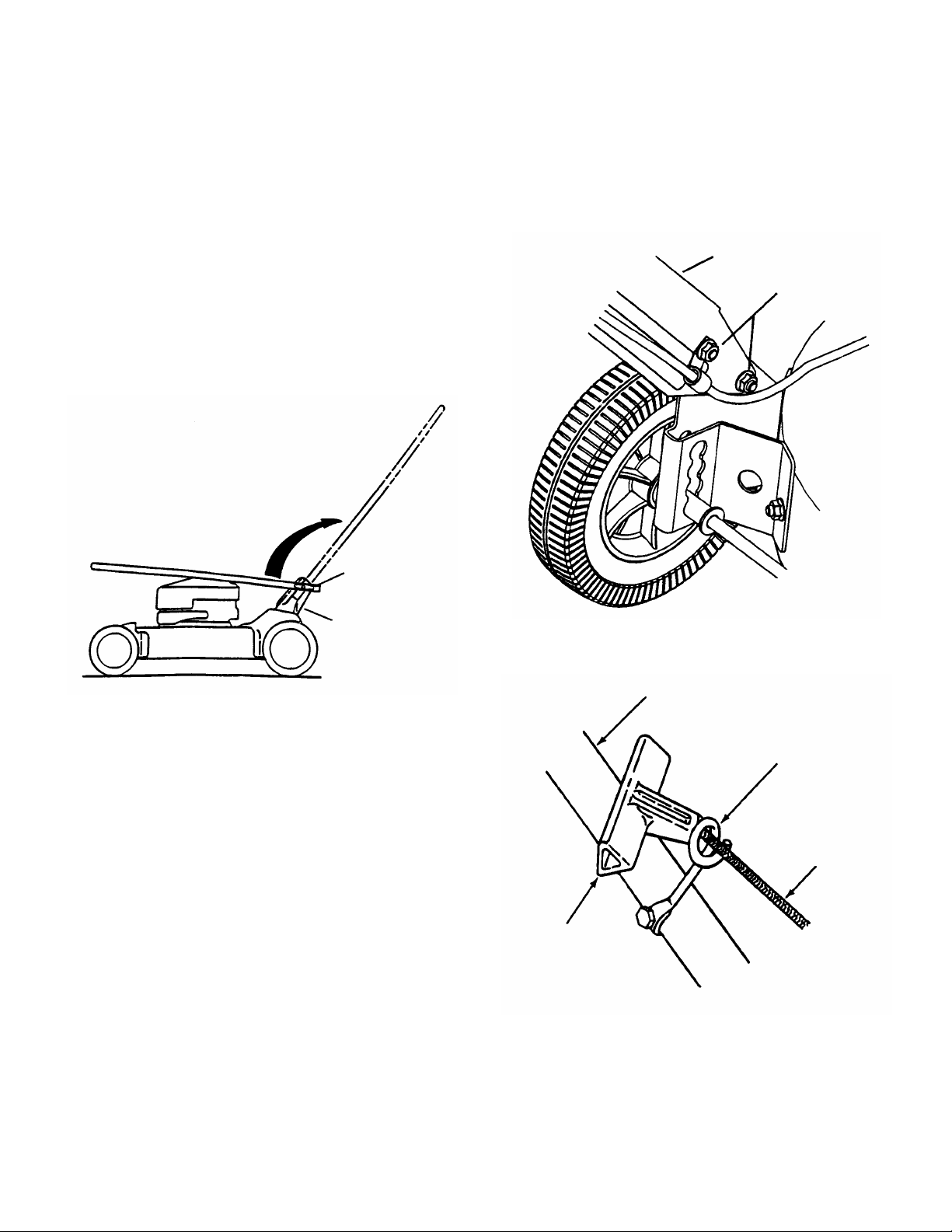
STEP 2: Tip mower back against the upper handle to gain
access to cutting blade. Remove foam shipping block
from cutting blade. T his must be removed bef ore starting
the engine.
STEP 3: Handle height is adjustable for differ ent height of
operators. Loosen the two nuts on the inside of each of
the lower handles. See Figure 2. Move the handle up or
down to the desired height. Retighten all nuts securely
after adjustment.
STEP 4: Pull blade c ontro l against upper handle, pull r ope
start handle and loop into rope guide. See Figure 3.
FIGURE 2
HANDLE
ROPE GUIDE
STARTER
ROPE
T-HANDLE
FIGURE 3
STEP 5: Set-up is now complete for push models
Proceed to checklist f ound on page 6 of this instruction
to prepare mower for use.
5
Page 6

DEALER CHECKLIST for SNAPPER
20” STEEL DECK WALK BEHIND MOWERS
The following must be achieved upon the purchase of the mower. It is very important that
the Dealer performs and accomplishes the set- up and the operational tests as listed below .
SET-UP (Details on Page 5 of this Instruction)
_____ FOAM SHIPPING BLOCK removed from cutting blade.
_____ UPPER HANDLE & LOWER HANDLE secured in place and hardware tightened securely.
_____ SIDE CHUTE, RECYCLING COVER or GRASS BAG installed on mower.
_____ BLADE retaining bolt(s) checked and tighten securely.
LUBRICATION
_____ ENGINE OIL added to bring level up to full mark on 4-cycle engines (Refer to Engine Manual).
OPERATIONAL TEST
_____ ENGINE started, engine control settings checked and adjusted as needed.
CPSC (Consumer Product Safety Commission) COMPLIANCE TEST
_____ BLADE CONTROL stops engine when released.
DEALER’S RECORDS & FINAL CHECK
_____ PERSONALLY HANDED Operator’s Manual & Mower Safety Booklet to purchaser.
_____ INSTRUCTED purchaser to read and follow instructions in Operator’s Manual.
_____ DEMONSTRATED proper starting procedure and operation of mower to purchaser.
_____ INSTRUCTED purchaser how to service air cleaner, maintain oil level (4-cycle).
_____ ASSISTED purchaser in completing Product Registration Card.
CONSUMER/OPERATOR PRODUCT REGISTRATION CARD
Purchase Date ___________________ Model _______________________ Serial No.________________________
Retailers Name ___________________________________ Signature _____________________________________
Address _____________________________________ City ____________________ State _______ Zip _______
MOWER WILL BE USED COMMERCIALLY? _______ YES _____ NO
Purchaser’s Name _________________________________ Signature ____________________________________
Address ____________________________________ City _____________________ State _______ Zip _______
IMPORTANT: This form is to be retained by the Dealer for future reference regarding Warranty, proof of
purchase, traceability for product recall or service, etc. Complete the Product Registration Card and Mail to
Customer Service Department at SNAPPER, P.O. BOX 1379, McDonough, Georgia, 30253.
6
Page 7

NOTE: This page is left blank so dealer can remove page 5 for future reference
regarding Warranty, proof of purchase, traceability for product recall or
service, etc.
7
Page 8
Section 1 - FAMILIARIZATION
ROPE START
T-HANDLE
UPPER
HANDLE
T-KNOB
LOWER
BRACKET
OIL FILL CAP
& DIPSTICK
1.1 INTRODUCTION
This manual has been prepared for the operator s of
the SNAPPER WALK BEHIND MOWERS. Its
purpose, aside from recommending operating and
routine service requirements, is to promote safety
through the use of accepted operating practices.
Read, Understand and Follow the “IMPORTANT
SAFETY INSTRUCTIONS” on Pages 2 & 3 of this
manual and all safety messages on the mower and
attachments before operating the mower.
SWITCH
BOX
RECYCLING
COVER
FIGURE 1.1
BLADE
CONTROL
BLADE
CONTROL
CABLE
COVER
KNOBS
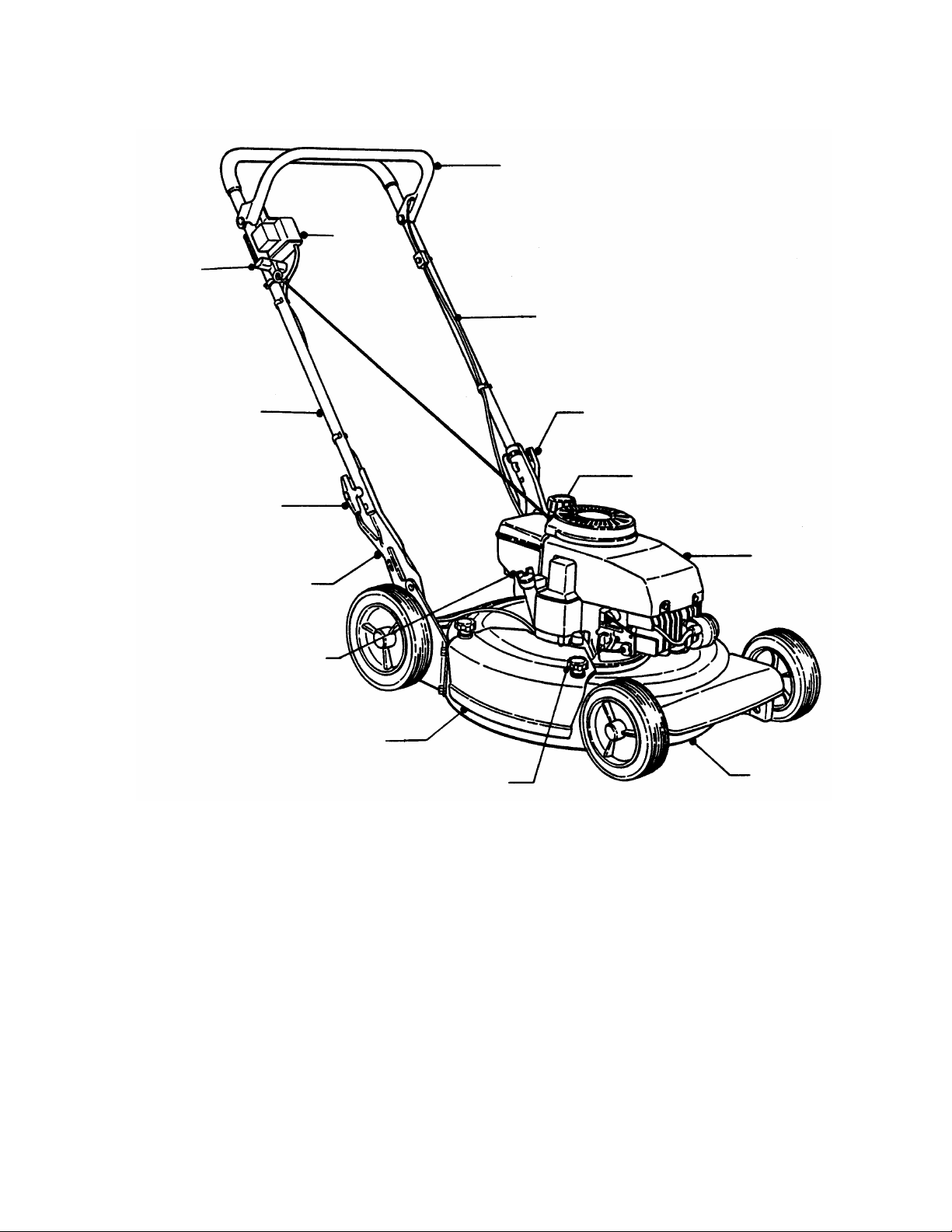
1.2 NOMENCLATURE
The nomenclatur e drawing above, Figure 1.1, shows
the essential parts of the SNAPPER W ALK BEHIND
MOWERS. It is recommended that all oper ators of
the mower become thoroughly familiar with the
controls, parts and operation of the mower before
operating. Specific details involving the engine are
found in the separate engine owner’s m anual. Study
these manuals before operating and keep both
handy for future reference.
8
T-KNOB
FUEL FILLER CAP
ENGINE
MOWER
DECK
Page 9

Section 2 - OPERATING INSTRUCTIONS
CONTR
OL
2.1 PRE-START CHECK LIST
Make the following checks and perform the service
required before each start-up.
2.1.1. Check guards, deflectors, grass bag, adapter
and covers to mak e sure all are in place and securely
tightened.
2.1.2. Check blade control to insure it works freely.
See Figure 2.1.
BLADE CONTROL
SHOWN IN “OFF”
POSITION
2.1.5. Add fuel to tank after pushing the mower
outside where fumes can safely dissipate. Make sure
cap is tightened after refueling. Refer to Engine
Owners Manual for specifications.
2.1.6. Clean exterior surfaces of cutting deck and
engine of any accumulation of spilled fuel, dirt, grass,
oil, etc. Keep engine air intake screen and cooling
fins clear at all times.
2.2 STARTING & OPERATION
2.2.1. ENGINE & BLADE
(Recoil Start)
1. Move engine speed control (Located on the side of
the engine) to the “FAST” rabbit position.
2. Push primer button three times to start a cold
engine. NOTE: Do not use primer button to start
warm engine. See Fi g u re 2 . 3 .
IMPORTANT: Stop the engine (and blade) by releasing
the blade control.
TURTLE
FIGURE 2.1
2.1.3. Check cutting height. Adjust to desired height.
2.1.4. Check engine oil and add oil as needed to bring
level up to the full mark. Refer to Engine Owner’s
Manual for oil specifications. See Figure 2.2.
DIPSTICK
MAXIMUM OIL
LEVEL
MINIMUM
OIL LEVEL
FIGURE 2.2
RABBIT
PRIMER
BUTTON
MOVE TO FAST
(RABBIT) POSITION
PUSH BUTTON
THREE TIMES
ENGINE SPEED
FIGURE 2.3
3. Pull blade control against handle.
4. Pull rope start handle to crank engine.
5. After engine starts, allow a brief warm-up until
engine runs smooth.
9
Page 10

Section 2 - OPERATING INSTRUCTIONS
Not More
2.2 STARTING & OPERATION
2.2.2. ENGINE & BLADE
(120 Volt Electric Start)
WARNING
The 120 volt electric start models are supplied with
a 10 foot three-wire power cord. The plug is
designed to operate on 120 volt AC household
current. It must be properly grounded at ALL times
to avoid the possibility of electric shock, which may
cause injury to the operator. Follow ALL
instructions carefully as set fo rth below. Determine
that your house wiring system is a three-wire
grounded system. Ask a licensed electrician if you
are not sure. If your house wiring system is not a
three-wire grounded system, DO NOT use this
electric start mower under any condition. If your
system is grounded and a three-hole receptacle is
NOT available, one should be installed by a licensed
electrician.
IMPORTANT: If using a power cord other than the one
supplied with machine, then use a power cord that is heavy
enough to carry the correct amount of current to the mower.
See chart, (OPTIONAL POWER CORDS) for correct size to
use depending on cord length and nameplate ampere
rating. If in doubt, use the next heavier gauge cord.
OPTIONAL POWER CORDS
MINIMUM GAUGE FOR CORD SETS
120 Volt Total Length of Cord in Feet
Rating - Amps 25 ft. 50 ft. 100 ft. 150 ft.
More
Than
Than
American Wire Gauge
0 6 18 16 16 14
6 10 18 16 14 12
10 12 16 16 14 12
12 16 14 12
1. Move engine speed control (Located on the side
of the engine) to the “FAST” rabbit position. See
Figure 2.4.
NOTE: DO NOT use prim er when using the elec tric st arter.
DO NOT use primer to restart a warm engine.
IMPORTANT: Stop the engine (and blade) by releasing
the blade control.
2. Connect power cord to the handle mounted
switch box. See Figure 2.5.
3. Plug opposite end of power cord into a three
hole grounded 120 Volt, AC receptacle.
Not Recommended
To avoid electrical sh ock o r injury, make sure po w er
cord is away from cutting blade before attempting to
start engine.
ENGINE
SPEED
CONTROL
PUSH BUTTON
TO START
PULL BLADE
CONTROL BACK
AGAINST HANDLE
(Starting procedure is continued on nex t page)
WARNING
TURTLE
RABBIT
MOVE TO FAST
(RABBIT) POSITION
FIGURE 2.4
SWITCH
BOX
ELECTRIC
POWER CORD
FIGURE 2.5
10
Page 11

Section 2 - OPERATING INSTRUCTIONS
2.2 STARTING & OPERATION
2.2.2. ENGINE & BLADE
(120 Volt Electric Start)
4. Stand in operator’s position. Move blade control
against handle and hold in place. See Figure 2.5.
WARNING
To avoid electrical sh ock o r injury, make sure po w er
cord is away from cutting blade before attempting to
start engine.
5. Depress starter button on switch box until engine
starts. See Figure 2.5. NOTE: If after 5 seconds of
cranking the engine and it does not start, releas e the
starter button. Attempt star ting again after waiting for
approximately 20 seconds.
6. After engine starts, allow a brief warm-up until
engine runs smooth. If engine f ails to start, check the
power cord. Be sur e it is inserted s ecurely into the AC
receptacle and into the switch box.
2.3 STOPPING
Stop engine and blade by releasing the blade
control. See Figure 2.6.
Before attempting any adjustments to the cutting height,
STOP the engine, remove the spark plug wire from the
spark plug and secure wire away from plug. DO NOT make
any adjustments with engine or blade running. Be
extremely careful when performing adjustments around
engine. Engine is extremely hot and can cause severe
burns. Wear heavy leather gloves when handling or
working around cutting blades. Blades are extremely
sharp and can cause severe injury.
2.4 HANDLE HEIGHT ADJUSTMENT
The height of the mower handle can be adjusted as
follows:
1. Loosen the lower nuts on each lower handle as
shown in Figure 2.7.
2. Move upper m ower handle up or down until the
desired position is achieved.
3. Tighten the lower nuts on each lower handle to
maintain desired position.
WARNING
LOWER HANDLE
LOOSEN TWO
NUTS
BLADE CONTROL
SHOWN IN “OFF”
POSITION
FIGURE 2.6
11
FIGURE 2.7
Page 12

Section 2 - OPERATING INSTRUCTIONS
ONLY!)
WARNING
Before attempting any adjustments to the cutting height,
STOP the engine, remove the spark plug wire from the
spark plug and secure wire away from plug. DO NOT make
any adjustments with engine or blade running. Be
extremely careful when performing adjustments around
engine. Engine is extremely hot and can cause severe
burns. Wear heavy leather gloves when handling or
working around cutting blades. Blades are extremely
sharp and can cause severe injury.
2.5 CUTTING HEIGHT ADJUSTMENT
1. FRONT WHEELS: Reposition the front axle by
raising the front wheels off the ground, then pull in the
spring loaded bushings until they clear the brackets.
Move bushings to the desired height of cut position
and release the bushings. See Figure 2.8.
2. REAR WHEELS: Reposition the rear axle by
raising the rear wheels off the ground, then pull in
the spring loaded bushings until they clear the
brackets. Move bushings to the desired height of
cut position and releas e the bushings. Position the
rear bushings in to the same notches corresponding
with notches for the front wheels to maintain the
level of the deck. See Figure 2.8.
NOTE: T here are four c utting height adjustment notc hes
on each wheel. The top notch is the lowest cutting height
and the lowest notch is the highest.
LOWEST
POSITION
FRONT
WHEEL
AXLE
BUSHING
3. Move ground speed control to slowest speed setting.
4. Proceed mowing slowly. If grass is very dense, lower
each rear wheel latch one notch lower than the front
wheel latches to improve recycling performance.
2.7 RECYCLING COVER
(REMOVAL/INSTALLATION)
1. REMOVAL: The recycling cover is secured in
place with two knobs. To remove the cover, unscrew
the two knobs and lift off the cover. See Figure 2.9.
2. INSTALLATION: When reinstalling the cover,
the deck sidewall should fit between the tab and
outside of cover. Tighten knobs securely. See
Figure 2.10.
RECYCLING
COVER
TURN KNOBS
CLOCKWISE
WHEN
REINSTALLING
SILHOUETTE
OF CUTTING
DECK
REMOVE BOTH KNOBS
BY TURNING
COUNTER-CLOCKWISE
FIGURE 2.9
CARRIAGE BOLT & NUT
(USED WITH SIDE
DISCHARGE CHUTE
DECK SIDE
WALL
HIGHEST
POSITION
FIGURE 2.8
2.6 RECYCLING OPERATION
NOTE: For best recycling results, cut up to a m aximum
of 1/3 of grass blade length and recycle ONLY when
grass is dry.
1. Set all wheels in the highest cutting position (Notch
4).
2. Move engine speed control to “FAST” (Rabbit)
position.
RECYCLING
COVER
TAB (SHOWS VIEW FROM
UNDERNEATH RECYCLING COVER)
FIGURE 2.10
12
Page 13

Section 3 - MAINTENANCE
FLANGES
3.1 INTRODUCTION
To retain the quality of the mower, use genuine
SNAPPER replacement parts only. Contact a local
SNAPPER dealer for parts and ser vice assistance.
For the correct part or information for a particular
mower, always mention model and serial number.
3.2 SERVICE - AFTER FIRST 5 HOURS
3.2.1. CHANGE ENGINE OIL
WARNING
Before attempting any adjustments or repairs, STOP
the engine, remove the spark plug wire from the
spark plug and secure wire away from plug. Wear
heavy leather gloves when handling or working
around cutting blades. Blades are extremely sharp
and can cause severe inju ry. Engine oil is extremely
hot and can cause sev ere burns. Allow engine oil to
cool before draining to prevent injury.
1. Disconnect spark plug wire and secure end away
from plug. The item s needed to perform oil change
are: cloth rags, (1) 3/8” drive ratchet with a short
extension and (1) shallow pan.
2. Tilt mower up on its rear wheels for access to
the oil drain plug located underneath the mower
deck. Do not tilt mower with spark plug or
carburetor down. See Figure 3.1.
5. Lower the mower down and place the piece of
wood under left rear wheel. Reach under mower
and remove drain plug and allow oil to drain out
completely in pan. Some oil may spill onto hands,
immediately wipe hands clean with cloth rags.
6. Tilt mower back up and replace drain plug.
Tighten securely but do not over tighten.
7. Fill engine with oil as specified in Engine
Owner’s Manual. Thereafter , change oil after each
25 hours of use.
IMPORTANT: DO NOT tip machine with carburetor or
spark plug down, oil from crank case will saturate the air
filter and cause the engine to hard start or not start at all.
If contamination does occur the air filter will have to be
replaced.
3.2.2 CHECK MOWER BLADE
1. Disconnect spark plug wire and secure end away
from plug.
2. Tilt mower up on its rear wheels for access to
the blade cap screw. Do not tilt mower with spark
plug or carburetor down. See Figure 3.2.
3. Check torque of blade retaining cap screw.
Recommended torque should be 30 to 40 ft. lbs.
See Figure 3.2.
4. Check blade for sharpness, wear and dam age. See
Section on Blade Wear Limits.
MAKE SURE THAT
BLADE HUB IS
BLADE
HUB
SEATED
BETWEEN
REMOVE OIL
PLUG
FIGURE 3.1
3. Place shallow pan underneath the approxim ate
center of the oil drain plug.
4. Loosen with ratchet and short extension, but do
not remove oil drain plug. Loosen plug until you can
turn it with your fingers.
FLANGE
BLADE
CONE WASHER
(Widest Part Up)
CAPSCREW TORQUE
30-40 FT. LBS.
FIGURE 3.2
13
Page 14

Section 3 - MAINTENANCE
3.3 ANNUALLY (END OF EACH SEASON)
Perform all m aintenance as described in the maintenance
schedule.
3.3.1. Engine
Service engine according to engine owner’s manual.
3.3.2. Air Filter
Refer to engine owner’s manual for service instructions.
3.3.3. Engine Oil
Refer to engine owner’s manual for service instructions.
3.4 STORAGE PROCEDURE
Refer to the Engine Owner’s Manual for directions
regarding engine storage preparations. Prepare the
mower for “end of season” storage as follows:
1. Drain fuel from fuel tank and let engine run until
all fuel is out of the carburetor.
2. Disconnect and remove the spark plug wire
away from spark plug before any other
preparations are made!
3. Tape all openings closed to prevent spraying
water into exhaust or air intakes during washing.
4. Tilt m ower up on its rear wheels and thoroughly
clean the underside of the deck . Do not tilt mower
with spark plug or carburetor down. Scrape away
any accumulation of grass with a putty knife and or
wire brush.
5. Lubricate all exposed metal with a light coating
of oil to prevent corrosion.
6. Loos en handle knobs. Car efully fold the handles
forward, “flexing” the c ontro l cables to pr event cable
damage.
7. Store the mower in a shed or other dry area,
protected from weather.
14
Page 15

Section 4 - ADJUSTMENTS & REPAIR
FLANGES
WARNING
Before attempting any adjustments o r repairs, STOP
the engine, remove the spark plug wire from the
spark plug and secure wire away from plug. Be
extremely careful when performing adjustments around
engine. Engine is extremely hot and can cause severe
burns. Wear heavy leather gloves when handling or
working around cutting blades. Blades are extremely
sharp and can cause severe injury.
4.1 MOWER BLADE REPAIR/REPLACEMENT
4.1.1. STANDARD BLADE WEAR LIMIT
1. Inspect blade frequently for signs of exces sive wear
or damage. See Figure 4.1.
NEW BLADE
BLADE
HUB
FLANGE
BLADE
CONE WASHER
(Widest Part Up)
CAPSCREW
MAKE SURE THAT
BLADE HUB IS
SEATED
BETWEEN
WEAR LIMIT
(NOTCH STARTS)
DANGEROUS CONDITION !
DO NOT USE ON MOWER !
REPLACE WITH NEW BLADE.
FIGURE 4.1
WARNING
Never use a cutting blade that shows signs of
excessive wear or damage. Refer to Section on
MOWER BLADE REPAIR/REPLACEMENT for proper
blade inspection and service procedures.
4.1.2. BLADE SHARPENING
1. Dis connect spark plug wire and secur e end away
from plug.
IMPORTANT: DO NOT tip machine with carburetor or
spark plug down, oil from crank case will saturate the air
filter and cause the engine to hard s tar t or not s tar t at all. If
contamination does occur the air filter will have to be
replaced.
2. Tilt mower up on its rear wheels.
3. Remove blade. See Figure 4.2.
4. Sharpen blade on a grinding wheel at an angle of 22
to 28 degrees. DO NOT sharpen blade beyond the
original cutting edge. See Figure 4.3.
FIGURE 4.2
NOTE: DO NOT
SHARPEN BEYOND
ORIGINAL
CUTTING EDGE.
22-28º
BLADE TIP
END VIEW
OF BLADE
ORIGINAL CUTTING EDGE
FIGURE 4.3
5. Check blade for balance. If necessary, correct
balance by grinding heavy end of blade.
6. Reinstall blade. Refer to Figure 3.2. Check torque
of blade retaining cap screw. Recom mended torque
should be 30 to 40 ft. lbs.
15
Page 16

TROUBLESHOOTING
PROBLEM PROBABLE CAUSE CORRECTIVE ACTION
Engine Will Not Start
Using Recoil Starter
Engine Will Not Start
Using Electric Starter
Engine Stalls or Stops
After Running
Engine Loses Power
Excessive Vibration
Cutting Grass
Improperly
Poor Grass Discharge
Oil Leaking
1. Fuel tank empty. 1. Fill fuel tank with fresh fuel.
2. Engine needs priming. 2. Push primer three times.
3. Spark plug wire disconnected. 3. Place spark plug wire onto spark plug.
4. Spark plug faulty. 4. Replace with new spark plug.
1. Fuel tank empty. 1. Fill fuel tank with fresh fuel.
2. Engine needs priming. 2. Push primer three times.
3. Power cord not plugged into switch box or AC outlet. 3. Plug in power cord to switch box & AC outlet.
4. Power cord damaged or severed. 4. Use new power cord of proper amperage.
5. Spark plug wire disconnected. 5. Place spark plug wire onto spark plug.
1. Blade control is released or is not being held
securely against handle.
1. Blade control should be held securely against
handle at all times during operation of
mower.
2. Fuel tank empty. 2. Fill with fuel to proper level.
3. Engine air pre-cleaner and or air cleaner dirty. 3. Clean free of all debris.
4. Spark plug defective or gap set improperly. 4. Service spark plug.
5. Water, debris or stale fuel in fuel system. 5. Drain and clean fuel system.
1. Engine air pre-cleaner or air cleaner dirty 1. Clean or replace filters.
2. Spark plug faulty. 2. Service spark plug.
3. Water, debris or stale fuel in fuel system. 3. Drain and clean fuel system.
1. Damaged, out of balance or bent mower blade. 1. Service mower blade.
2. Loose blade components. 2. Service and tighten loose parts.
3. Loose or missing air lift (if equipped). 3. Replace air lifts. Tighten to proper torque.
1. Cutting height too low or high. 1. Adjust cutting height.
2. Engine speed too slow. 2. Move engine speed control to “FAST” position.
3. Forward ground speed too fast. 3. Move ground speed control to a slower speed.
4. Terraced cut, side to side. 4. Adjust height of cut with height adjust bushings.
5. Excessive deck pitch, front to rear. 5. Adjust height of cut with height adjust bushings.
6. Cutting blade dull or damaged. 6. Sharpen cutting edges or replace blade.
1. Engine speed too slow. 1. Move engine speed control to “FAST” position.
2. Grass is wet. 2. Mow when grass is dry .
3. Excessively worn or damaged blade. 3. Service mower blade.
4. Build up of grass clippings and debris under deck. 4. Clean deck.
5. Improper blade installed on deck. 5. Install proper SNAPPER blade.
6. Blade installed improperly on deck. 6. Install blade properly.
1. Leaking engine case. 1. Contact authorized SNAPPER dealer.
2. Check and tighten drain plug.
3. Make sure dipstick or oil filler cap is securely in
place.
16
Page 17

ITEM SERVICE PERFORMED
Engine Oil
Check Oil Level Page 9
SERVICE SCHEDULE
REF. EACH
USE 5 HRS
X
25
HRS
50
HRS
100
HRS
EACH
SEASON
Air Pre-Cleaner
Air Cleaner
Spark Plug
Engine Cooling
System
Mower Blade
Mower Deck
* Change oil every 25 hours when operating under heavy load or high temperatures.
**Clean more often under dusty conditions or when air debris is present
4.2. MAINTENANCE/REPLACEMENT PARTS
Initial Oil Change Page 9
Periodic Oil Change Page 13
Clean Sponge Element Engine Manual
& Page 14.
Clean or Replace Engine Manual.
Replace Engine Manual.
Clean Shroud & Fins Engine Manual
Check For Wear, Damage
& Replacement
Clean Debris
Accumulation
Page 15
Page 14
X
X*
X**
X**
X
X**
X
X
MAINTENANCE PARTS
Blade Control Cable 3-5493
Cutter Blade (Mulching) 1-7167
Parts Manual for 20” Steel Deck Walk Behind Mower Series 13 06058
17
Page 18

3 YEAR LIMITED WARRANTY
For three (3) years from pur chase date f or the original pur chaser 's res idential, non-com m erc ial use, SNAPPER, through
any authorized SNAPPER dealer will replace, free of charge (except for taxes where applic able), any part or parts found
upon examination by the factory at McDonough, Georgia, to be defective in material or workmanship or both.
For ninety (90) days from purchase date for the or iginal purchaser's commercial, rental, or other non-residential use,
SNAPPER, through any authorized SNAPPER dealer will replace, free of charge, any part or parts found upon
examination by the factory at McDonough, Georgia, to be defective in material or workmanship or both.
All transportation costs incurred by the purchaser in submitting material to an authorized SNAPPER dealer for
replacement under this warranty must be paid by the purchaser.
This warranty does not apply to engines and their components , and batteries, as these item s are warranted separately.
This warranty does not apply to parts that have been damaged by accident, alteration, abuse, improper lubrication,
normal wear, or other cause beyond the control of SNAPPER. This warranty does not cover any machine or com ponent
part that has been altered or modified changing safety, performance, or durability.
Batteries have a one (1) year prorated warranty period with free replacement if requir ed during the first ninety (90) days
from the original purchas e date. SNAPPER will not be responsible for any installation cost incurred. T he battery warranty
only covers original equipment batteries and does not cover dam age to the battery or machine caused by neglect or
abuse, destruction by fire, explosion, freezing, overcharging, improper maintenance, or use of improper electrolyte.
There is no other express warranty.
DISCLAIMER OF WARRANTY
Implied warranties, including those of merchantability and fitness for a particular purpose, are limited to three
(3) years from purchase date for the original purchaser's residential or other non-commercial use, and ninety
(90) days from purchase for the original purchaser's commercial, rental or other non-residential use, and to the
extent permitted by law, any and all implied warranties are excluded. This is the exclusive remedy. Liabilities for
consequential damages, under any and all warranties are excluded.
Some states do not allow limitations on how long an implied warranty lasts, or do not allow the exclusion or
limitation of incidental or consequential damages, so the above limitation or exclusion may not apply to you.
This warranty gives you specific legal rights, and you may also have other rights which vary from state to state.
WARNING: THE USE OF REPL ACEMENT PARTS OTHER THAN GENUINE SNAPPER PARTS MAY IMPAIR THE
SAFETY OF SNAPPER PRODUCTS AND WILL VOID ANY LIABILITY AND WARRANTY BY SNAPPER
ASSOCIATED WITH THE USE OF SUCH PARTS.
IMPORTANT: Please fill out the attached SNAPPER Product Registration Card immediately and mail to:
Snapper’s Product Registration Ce nter, P.O. Box 1379, McDonough, Georgia 30253
18
Page 19

PRIMARY MAINTENANCE
An illustration of how
dirt can damage your
engine & how
able maintenance
Snapper uses the
best available
engines and
components in
their products in
order to provide
long, satisfactory
service. However,
proper care is
essential in
life. Dirt is your
engine’s enemy
The engine on your Snapper
product spends its entire life
operating close to the ground at
high speed creating a virtual
reason
can protect it!
prolonging engine
number 1!
storm of dust and dirt!
19
Page 20

The engine must gulp
As the dirt particles are stopped, they build up
and begin to clog the outside of the air filter.
This reduces the amount of air available to the
el mixture
clogged
air cleaner will:
Damage caused by a poorly serviced air
cleaner is not covered under the engine
warranties. So, save yourself unnecessary
expenses and undue aggravation by keeping
the air cleaner properly serviced at the
d in the engine owner’s
It doesn’t take long to service an air cleaner.
Follow the specific instructions in the engine
owner’s manual for the type filter used.
Prevent dirt from falling into the carburetor
ake
sure components are installed in correct
sequence after servicing to prevent unfiltered
air from entering the engine. Some servicing
about 12,000 gallons
of air for every gallon
of fuel used. Because
of its working
environment, the air
available to your
Snapper engine is
heavily saturated with
airborne dirt particles.
PRIMARY MAINTENANCE
Knowing the dirt will
quickly ruin an engine,
manufacturers equip their
engine with extremely
efficient air cleaners to
filter out the harmful dirt.
engine and causes an over-rich fu
which results in the following adverse effects:
An improperly serviced, dirt
1. Increase fuel
2. Cause power loss.
3. Result in hard
4. Create smoke from
5. Produce carbon
6. Foul spark plug
7. Score cy linder walls.
8. Burn valves.
9. Wear out the engine
10. COST YOU MONEY!
intervals specifie
manual.
intake when servicing your air cleaner. M
consumption.
hints on several common types are:
starting.
unburned fuel.
build-up internally.
electrodes.
pre-maturely.
20
Page 21

PRIMARY MAINTENANCE
such as:
Air is also needed to keep
your engine cool. Dirt, dust &
debris build up restricts and
clogs cooling air intake
screens and fins. Clean
screens and fins at frequent
intervals. The engine blower
housing and shrouds should
be removed at least once
each season or more often
under dry, dusty conditions
for a thorough cleaning of
fins.
Generally, wash foam-type filters in
a dishwashing detergent and water
solution. Rinse and wring dry, then
saturate with oil and squeeze out
excess. Failure to re-oil this type
filter will ruin the engine.
Clean paper elements by tapping
lightly. Blowing with air will rupture
paper elements.
Use a flashlight to detect clogged
or torn paper elements – replace if
damaged in any way.
Dirt can also be
introduced into an engine
in dirty fuel from a
contaminated container.
Always use clean fresh
fuel from a clean
container to guard
against dirt, sludge and
water contamination.
Failure to keep external surfaces
clean not only presents fire
hazards, but causes overheating
and resulting engine damages
1. Distorted valve
guides.
2. Sticking Valves.
3. Scuffed, scored
cylinder walls.
4. Over-speeding.
5. Loss of power.
6. Complete failure
of engine.
Be aware that fuel
breaks down in
storage and forms
gummy compounds
which will block
carburetor passages.
Never use fuel more
than 3 months old.
Drain tank then run
the engine out of fuel
before storing during
the off-season.
An engine must also have proper lubrication. All
engines use some oil. On 4-cycle engine,
CHECK OIL LEVEL BEFORE EACH START-UP.
Wipe area clean around the oil check plug or
dipstick opening to keep dirt from falling into
the engine when checking the oil. Always check
with the machine on a level surface. On engines
with dipstick, keep the level up to, but not over,
the FULL mark. When adding oil, allow time for
all of the oil to flow dow n the fill tube to prevent
a false full reading when the level could actually
be low and result in engine damage.
21
Page 22

point of overflowing at the
engin
e owner’s manual for oil details.
Read and follow all
safety instructions in
safety booklets and
Keep in mind that dirt is your engine’s
both internally and externally!
n engine
and externally it will cause overheating and
resulting internal damages. Damage caused
by improper lubrication, poor air cleaner
service or overheating due to dirt cannot be
a few moments to service the engine
(and equipment) on a routine basis but the rewards
will be a quick starting, responsive engine that will
provide long satisfactory service with minimum
start checklist in the next
tructions in your Snapper Operator’s
Manual are designated to help you keep your Snapper
On 4-cycle engines with an oil
level plug, don’t be fooled onto
thinking the engine has
sufficient lubricating oil if you
can see “some” oil in the
opening – the level should
always be brought up to the
top of the fill hole.
PRIMARY MAINTENANCE
On 2-cycle engines, lubrication must be
provided by an exact mixture of gasoline
and 2-cycle air-cooled engine oil. A 2-cycle
engine that is mistakenly run on straight
gasoline will be ruined in less than 5
minutes! If you keep straight gasoline in
addition to pre-mixed 2-cycle engine fuel,
be sure the containers are clearly marked
to avoid mix-up.
Snapper 2-cycle engines require a 32 to 1
mixture of gasoline and BIA certified TC-W
oil such as Snapper’s 2-cycle engine oil.
Many of the 2-cycle engine oils on the
market today make fantastic claims, but for
the best performance and long engine life,
always use Snapper 2-cycle oil. Pre-mix the
fuel and always shake the container before
filling the tank.
Change oil at regular intervals using a high
quality oil such as Snapper’s small engine
formulated 4-cycle engine oil. Refer to the
1. Engine Oil To full level (4-cycle).
Properly mixed with gas
(2- cycle).
2. Air Cleaner Clean and properly ser viced.
Full fresh clean gasoline.
3. Fuel T ank Fuel valve open.
Cap vent open.
Inline filter clean.
4. Choke Operating properly.
5. Primer (on Used properly.
some engines)
6. Safety Interlock In proper position.
Switches All wires properly connected.
7. Switch & Blade Switch On.
Control Blade control properly
positioned on walk mower.
8. Spark Plug Wire connected.
Good connection.
9. Throttle Control Start Position.
10. Blade Properly installed and
torqued.
Sharpened.
11. Muffler Good condition.
Not clogged.
Grass & leaves cleaned away.
manuals.
enemy #1
Internally, dirt will quickly ruin a
covered under warranty.
It only takes
maintenance cost. The precolumn and ins
in top operating condition with minimum effort!
22
Page 23

SERVICE NOTES
______________________________________________________________________________
______________________________________________________________________________
______________________________________________________________________________
______________________________________________________________________________
______________________________________________________________________________
______________________________________________________________________________
______________________________________________________________________________
______________________________________________________________________________
______________________________________________________________________________
______________________________________________________________________________
______________________________________________________________________________
______________________________________________________________________________
______________________________________________________________________________
______________________________________________________________________________
______________________________________________________________________________
______________________________________________________________________________
______________________________________________________________________________
______________________________________________________________________________
______________________________________________________________________________
______________________________________________________________________________
______________________________________________________________________________
______________________________________________________________________________
______________________________________________________________________________
______________________________________________________________________________
______________________________________________________________________________
______________________________________________________________________________
______________________________________________________________________________
______________________________________________________________________________
______________________________________________________________________________
______________________________________________________________________________
______________________________________________________________________________
______________________________________________________________________________
______________________________________________________________________________
______________________________________________________________________________
______________________________________________________________________________
______________________________________________________________________________
______________________________________________________________________________
______________________________________________________________________________
______________________________________________________________________________
______________________________________________________________________________
______________________________________________________________________________
______________________________________________________________________________
______________________________________________________________________________
______________________________________________________________________________
______________________________________________________________________________
______________________________________________________________________________
______________________________________________________________________________
______________________________________________________________________________
23
Page 24

SERVICE NOTES
______________________________________________________________________________
______________________________________________________________________________
______________________________________________________________________________
______________________________________________________________________________
______________________________________________________________________________
______________________________________________________________________________
______________________________________________________________________________
______________________________________________________________________________
______________________________________________________________________________
______________________________________________________________________________
______________________________________________________________________________
______________________________________________________________________________
______________________________________________________________________________
______________________________________________________________________________
______________________________________________________________________________
______________________________________________________________________________
______________________________________________________________________________
______________________________________________________________________________
______________________________________________________________________________
______________________________________________________________________________
______________________________________________________________________________
______________________________________________________________________________
______________________________________________________________________________
______________________________________________________________________________
______________________________________________________________________________
______________________________________________________________________________
______________________________________________________________________________
______________________________________________________________________________
______________________________________________________________________________
______________________________________________________________________________
______________________________________________________________________________
______________________________________________________________________________
______________________________________________________________________________
______________________________________________________________________________
______________________________________________________________________________
______________________________________________________________________________
______________________________________________________________________________
______________________________________________________________________________
______________________________________________________________________________
______________________________________________________________________________
______________________________________________________________________________
______________________________________________________________________________
______________________________________________________________________________
______________________________________________________________________________
______________________________________________________________________________
______________________________________________________________________________
______________________________________________________________________________
______________________________________________________________________________
24
Page 25

Safety Instructions & Operator’s Manual for
20” STEEL DECK
WALK BEHIND MOWERS
SERIES 13
WARNING:
COPYRIGHT © 1999
SNAPPER INC.
ALL RIGHTS RESERVED
The engine exhaust from this product contains chemicals known to the State
of California to cause cancer, birth defects or other reproductive harm.
MANUAL No. 7-2036 .(REV. 1, 5/17/99)
25
 Loading...