

Page 1
_Safety Instructions& Operator's Manual for
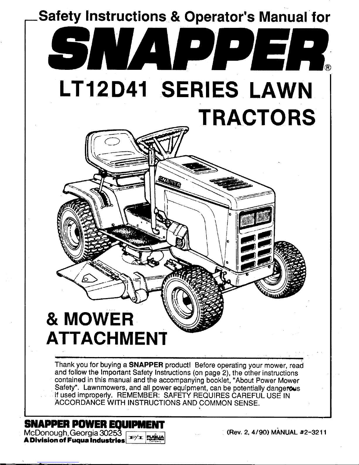
LT12D41 SERIES LAWN
TRACTORS
& MOWER
ATTACHMEN'r
Thank you for buying a SNAPPER product! Before operating your mower, read
and follow the Important Safety Instructions(on page 2), the other instructions
contained in this manual and the accompanying booklet, "About Power Mower
Safety". Lawnmowers, and all power equipment, can be potentially dangerous
if used improperly. REMEMBER: SAFETY REQUIRES CAREFUL USE IN
ACCORDANCE WITH INSTRUCTIONS AND COMMON SENSE.
SNAPPER POWEREQUIPMENT
McDonough, Georgia 30253
ADivismnof Fuqualndustrles :_/_ I_I
(Rev. 2. 4/90) M,_NUAL #2-3211
Page 2

IMPORTANT SAFETY INSTRUCTIONS
WARNING: This powerful cutting machine is capable of
amputating hands and feet and can throw objects that can
cause injury and damage! Failure to observe the following
safety instructions could result in serious injury. Carefully
read this manual and question your dealer if something is
not clear. Should the dealer be unable to answer to your
satisfaction, write or call the Customer Service Depart-
ment at SNAPPER Power Equipment, McDonough,
Georgia 30253 (phone 404-957.9141).
PROTECTION FOR CHILDREN
1,
2.
DO NOT allow children in yard when machine is
operated.
DO NOT allow children to ride on machine or on at-
tachments.
3. DO NOT allow pre-teenage children to operate
machine.
4. Only responsible teenagers with mature judgement
shall be allowed to operate machine and only under
close supervision.
PROTECTION AGAINST TIPOVERS
1.
2,
DO NOT operate machine on slopes exceeding 15°
(27% grade),
On slopes above 10° (18% grade); exercise extreme
caution; turn blade OFF when traveling uphill;
reduce speed , ayoid sharp turns.
3,
4.
Avoid uphill starts. If machine is stopped going
uphill, turn blade off and back slowly down the slope.
DO NOT mow under any condition where traction or
stability is doubtful without first test driving over the
terrain with blade OFF.
5. Stay alert for holes and other hidden hazards and
keep away from ditches, washouts, culverts, fences
and protruding objects.
6. DO NOT mow back and forth across face of slopes.
7. KEEP A SAFE DISTANCE (at least three feet) away
from edge of ditches and other drop offs.
OTHER IMPORTANT PRECAUTIONS
1. Read and follow operator's manuals and instructions
furnished with attachments.
2. Only mature, responsible persons shall operate the
machine.
3,
4.
5.
6.
7.
Mount and dismount machine from left side.
Wear appropriate protective clothing when mowing
such as long pants and substantial footwear, not
barefoot or with open sandals.
Practice operation of machine with blade OFF to
learn controls and develop skill.
Persons under the influence of alcohol or drugs must
not operate machine.
Know how to stop blade and engine quickly in
preparation for emergencies.
8,
9.
10.
11.
12.
13.
14.
15.
16.
17.
18.
19.
20.
21.
22.
23.
24.
25.
26.
27.
2
Keep people and pets a safe distance from machine.
Shields, deflectors, switches, blade controls and
other safety devices must be in proper position and
functional.
Clear area to be worked of wire, rocks and other ob-
jects that could cause injury if thrown by blade.
STOP blade, stop engine and remove key when leaw
ing machine.
DO NOT operate machine unless properly seated
with feet on foot rests or pedal.
Keep hands and feet away from rotating blade
underneath deck. Never place foot on ground while
blade is ON or when machine is in motion!
Turn blade OFF, stop engine and wait for blade to
stop before attempting to unclog grass or leaves to
prevent loss of fingers or hand.
Blade must be OFF except when cutting grass.
Set cutter in highest position When mowing over
rough ground.
Deflector or arass catcher must be in eosition. Never
point discharge at people, passing cars, windows or
doors. Watch out for traffic when crossing or near
roadways.
Operate in reverse only after careful observation of
entire area behind the machine. DO NOT mow in
reverse unless absolutely necessary.
Service machine and make adjustments only when
engine is stopped.
Have machine serviced by an authorized Snapper
dealer at least once a year and have the dealer install
any new safety devices.
Use only genuine Snapper replacement parts to
assure that original standards are maintained.
Tighten all nuts, bolts, screws, frequently and check,
adjust, repair or replace brakes as needed.
Lubricate machine at intervals specified in manual to
prevent controls from binding.
Mow only in daylight or with good artificial light.
Handle gasoline with care! Never remove cap while
engine is running. Fill tank outdoors only with engine
stopped and cool. Clean spilled gasoline from
machine. Store gasoline in approved container, out
of the reach of children, in well ventilated, unoc-
cupied building.
DO NOT change engine governor speed settings or
overspeed engine.
Check grass catcher components frequently for
signs of wear or deterioration and replace as needed
to prevent injury from items going through weak or
worn spots.
Exercise caution when pulling loads. Limit loads to
those you can safely control and attach loads to
hitch plate as specified with Snapper attachment in-
structions.
Page 3
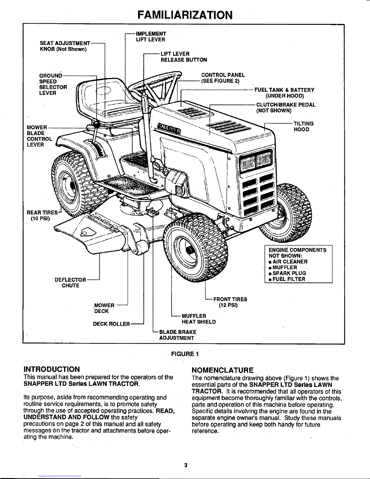
FAMILIARIZATION
SEAT ADJUSTMENT--
KNOB (Not Shown)
GROUND
SPEED
SELECTOR
LEVER
MOWER
BLADE
CONTROL
LEVER
MFTLEVER
RELEASE BUTTON
CONTROL PANEL
_)
FUEL TANK & BATTERY
(UNDER HOOD)
CLUTCH!BRAKEPEDAL
(NOTSHOWN)
TILTING
HOOD
(10 PSI)
/
DEFLECTOR
CHUTE
MOWER
DECK
DECK ROLLER--
MUFFLER
HEAT SHIELD
BLADE BRAKE
ADJUSTMENT
' FIGURE i
INTRODUCTION
This manual has been prepared for the operators of the
SNAPPER LTD Series LAWN TRACTOR.
Its purpose, aside from recommending operating and
routine service requirements, is to promote safety
through the use of accepted operating practices. READ,
UNDERSTAND AND FOLLOW the safety
precautions on page 2 of this manual and all safety
messages On the tractor and attachments before oper-
ating the machine.
ENGINE COMPONENTS
NOT SHOWN:
• AIR CLEANER
• MUFFLER
• SPARK PLUG
• FUEL FILTER
(12 PSI)
NOMENCLATURE
The nomenclature drawing above (Figure 1) shows the
essential parts of the SNAPPER LTD Series LAWN
TRACTOR. It is recommended that all operators of this
equipment become thoroughly familiar with the controls,
parts and operation of this machine before operating.
Specific details involving the engine are found in the
separate engine owner's manual. Study these manuals
before operating and keep both handy for future
reference.
Page 4
OPERATING INSTRUCTIONS
BEFORE OPERATING:
Be thoroughly familiar with all controls and how to use
them before operating your mower. Know beforehand
how to stop the engine, wheel drive and mower blade in
preparation for possible emergencies.
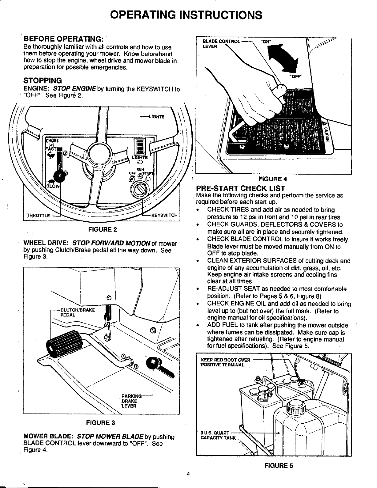
STOPPING
ENGINE: STOP ENGINE by turning the KEYSWITCH to
"OFF". See Figure 2.
FIGURE 2
WHEEL DRIVE: STOP FORWARD MOTION of mower
by pushing Clutch/Brake pedal all the way down. See
Figure 3.
/
/
FIGURE 3
MOWER BLADE: STOP MOWER BLADE by pushing
BLADE CONTROL lever downward to "OFF" See
Figure 4.
FIGURE 4
PRE-START CHECK LIST
Make the following checks and perform the service as
required before each start up.
,, CHECK TIRES and add air as needed to bring
pressure to 12 psi in front and 10 psi in rear tires.
• CHECK GUARDS, DEFLECTORS & COVERS to
make sure all are in place and securely tightened.
• CHECK BLADE CONTROL to insure it works freely.
Blade lever must be moved manually from ON to
OFF to stop blade.
• CLEAN EXTERIOR SURFACES of cutting deck and
engine of any accumulation of dirt, grass, oil, etc.
Keep engine air intake screens and cooling fins
clear at all times.
• RE-ADJUST SEAT as needed to most comfortable
position. (Refer to Pages 5 & 6, Figure 8)
• CHECK ENGINE OIL and add oil as needed to bring
level up to (but not over) the full mark. (Refer to
engine manual for oil specifications).
• ADD FUEL to tank after pushing the mower outside
where fumes can be dissipated. Make sure cap is
tightened after refueling. (Refer to engine manual
for fuel specifications). See Figure 5.
KEEP REDBOOT OVER
'POSITIVETERMINAL
FIGURE 5
4
Page 5
OPERATING INSTRUCTIONS
STARTING & OPERATING
ENGINE: START ENGINE as foliows:
1. PUSH BLADE CONTROL LEVER downward to
"OFF" position (Fig. 4) and fully depress the
CLUTCH/BRAKE pedal (Fig. 7), so that Safety
Interlock System will allow engine to start.
2. CHOKE ENGINE for cold starting by moving
THROTTLE CONTROL to "CHOKE" position.
(Little or no choking will be needed when restarting
awarm engine). Referto Figure 2.
NOTE
THE SEAT INTERLOCK FUNCTIONS TO SHUT
OFF THE ENGINE IN THE EVENT THE OPERA-
TOR VACATES THE SEAT WITH THE TRACTION
DRIVE ENGAGED AND/OR THE MOWER BLADE
ENGAGED, IN THE EVENT OF AN INTERLOCK
MALFUNCTION, DO NOT OPERATE THE TRAC-
TOR UNTIL THE CONDITION IS CORRECTED.
3. Insert key in ENGINE IGNITION switch, turn key to
"START" position to crank engine and hold until
engine starts then release.
NOTE
LIMIT CRANKING INTERVALS TO FIVE
SECONDS DURATION TO PREVENT
OVERHEATING OF STARTING MOTOR
AND/OR DEPLETION OF BATTERY ENERGY.
NORMALLY, FIVE SECONDS IS SUFFICIENT
CRANKING TIME FOR STARTING. IF THIS
TIME IS EXCEEDED, LOCATE AND COR-
RECT CAUSE OF STARTING PROBLEM.
4=
WARM-UP ENGINE momentarily, then move the
THROTTLE CONTROL downward out of CHOKE
position until engine runs smoothly. Set desired
speed, Best cutting and bagging performance is
obtained with engine at or near top speed.
TO START MOTION
L
After theengine hasbeen startedand is running
smoothly, proceedas follows to startforward or
rearward motion.
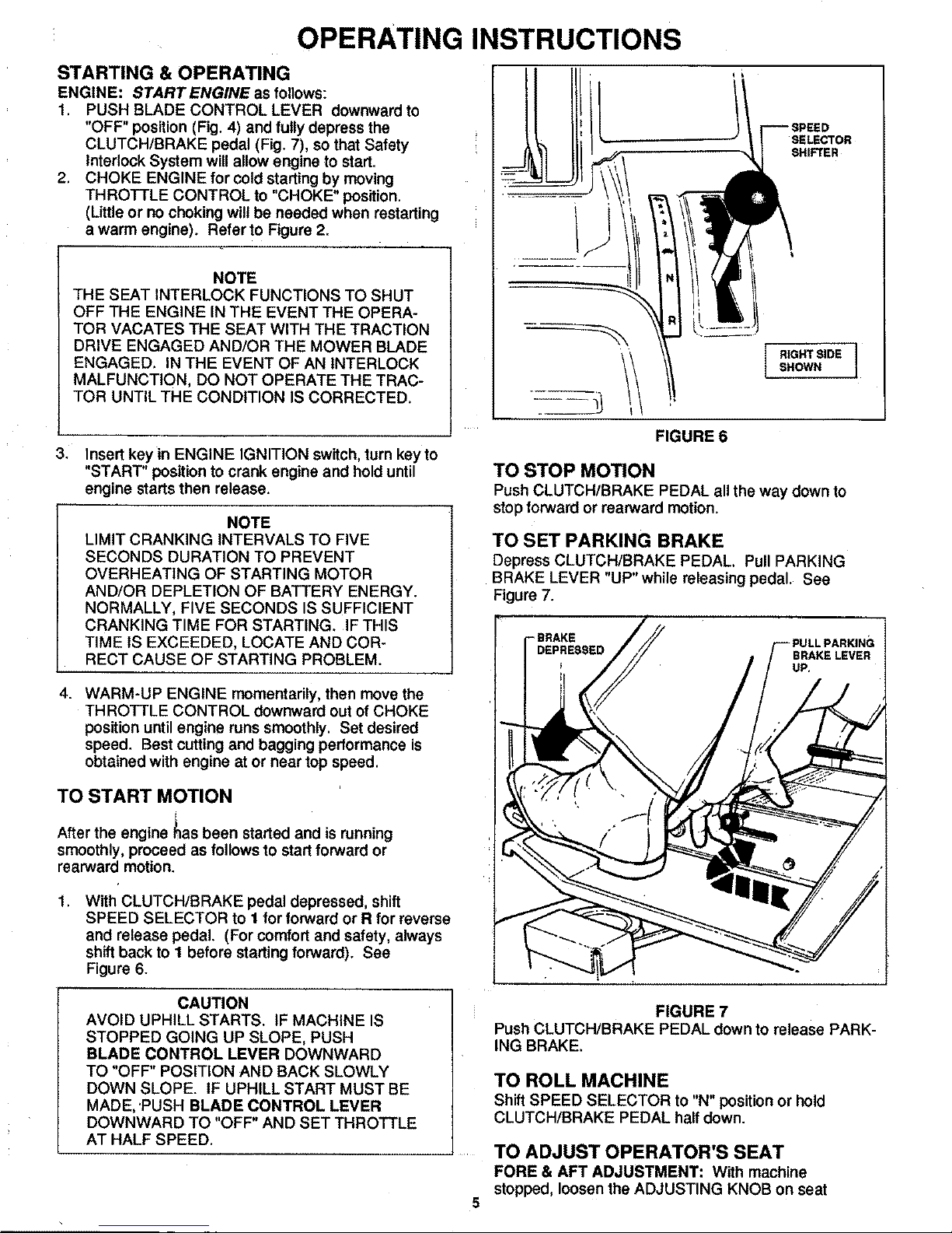
,
With CLUTCHIBRAKE pedal depressed, shift
SPEED SELECTOR to I for forward or R for reverse
and release pedal. (For comfort and safety, always
shift back to I before starting forward). See
Figure 6.
II SELECTOR
SHIFTER
FIGURE 6
I RIGHT SIDE
SHOWN
TO STOP MOTION
Push CLUTCH/BRAKE PEDAL all the way down to
stop forward or rearward motion.
TO SET PARKING BRAKE
Depress CLUTCH/BRAKE PEDAL Pull PARKING
BRAKE LEVER "UP"while releasing pedal. See
Figure 7.
SRAKE
DEPRESSED
CAUTION
AVOID UPHILL STARTS. IF MACHINE IS
STOPPED GOING UP SLOPE, PUSH
BLADE CONTROL LEVER DOWNWARD
TO "OFF" POSITION AND BACK SLOWLY
DOWN SLOPE. IF UPHILL START MUST BE
MADE, 'PUSH BLADE CONTROL LEVER
DOWNWARD TO "OFF" AND SET THROTTLE
AT HALF SPEED.
FIGURE 7
Push CLUTCH/BRAKE PEDAL down to release PARK-
ING BRAKE.
TO ROLL MACHINE
Shift SPEED SELECTOR to "N" position or hold
CLUTCH/BRAKE PEDAL half down.
TO ADJUST OPERATOR'S SEAT
FORE & AFT ADJUSTMENT: With machine
stopped, loosen the ADJUSTING KNOB on seat
5
Page 6
OPERATING INSTRUCTIONS
support. Sit in operators seat and, while depressing
the CLUTCH/BRAKE PEDAL, slide the seat forward
or rearward to the most comfortable position,
then lock in position by tightening ADJUSTING KNOB.
See Figure 8.
FIGURE 8
TO OPERATE MOWER
During transport or for clearance through gates it may
become necessary to raise the DISCHARGE DE-
FLECTOR. Reinstall the wing nuts on the studs when
the DEFLECTOR is raised so they will not be lost. Be
sure to lower the DEFLECTOR and clamp it securely
down with the wing nuts before mowing. See Figure 9.
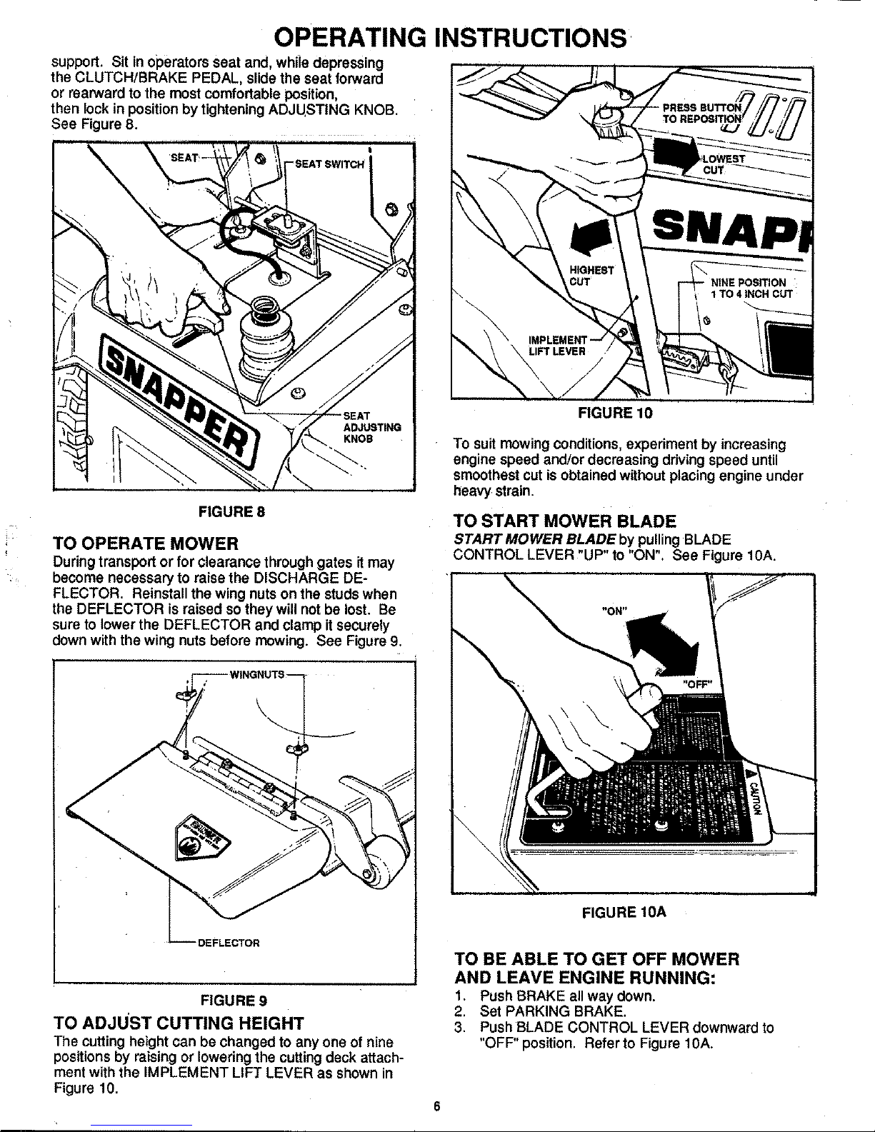
FIGURE 10
To suit mowing conditions, experiment by increasing
engine speed and/or decreasing driving speed until
smoothest cut is obtained without placing engine under
heavy strain.
TO START MOWER BLADE
START MOWER BLADE by pulling BLADE
CONTROL LEVER "UP" to "ON". See Figure 10A.
\
DEFLECTOR
FIGURE 9
TO ADJUST CUTTING HEIGHT
The cutting height can be changed to any one of nine
positions by raising or lowering the cutting deck attach-
ment with the IMPLEMENT LIFT LEVER as shown in
Figure 10.
FIGURE 10A
TO BE ABLE TO GET OFF MOWER
AND LEAVE ENGINE RUNNING:
1. Push BRAKE all way down.
2. Set PARKING BRAKE.
3. Push BLADE CONTROL LEVER downward to
"OFF" position. Refer to Figure 10A.
Page 7

SERVICE
To retain the quality of your tractor, use Genuine
_APPER Replacement Parts only. Contact your local
SNAPPER Dealer for parts and service assistance. For
the correct part or information for your particular mower,
always mention model and serial number. We reCo-
mmend returning the tractor to an authorized SNAPPER
Dealer on a yearly basis for inspection and addition of
any new devices which might upgrade the safety of your
mower. For the nearest SNAPPER Dealer, check the
yellow pages under the heading LAWN MOWERS, For
engine parts and service, look for the engine manufact-
urer's dealers under the heading ENGINES-gasoline.
DRAINING ENGINE OIL
MAINTENANCE & LUBRICATION
_eCHEDULE
fer to the Engine=Owner's Manual for service spaci-
fications on the engine itself, The following applies
primarily to the tractor and optional mower attacWnents.
Clean fittings before greasing,
FIRST 5 HOURS (NEW UNIT)
• ENGINE: Change oil in crankcase. Refer to
Engine Owner's Manual, and Draining Engine
Oil on this page.
• TRACTOR: Check all fasteners and retighten as
needed.
NOTE
RAISE HOOD. (IT MAY BE MORE CONVEN-
IENT TO REMOVE HOOD FOR EASIER
ACCESS WHEN FILLING WITH OIL. SEE
"HOOD REMOVAL", PAGE 12.
1. Disconnect spark plug wire,
2. Fashion an oil drain trough from metal or cardboard
as shown in Figure 11.
I--7[
BEND UP 90" AT CENTER I" _"
4 TO 6 INCH_ -_
FIGURE 11
.
i
4.
Loosen oil _lrain plug. Place trough under plug.
Place a flat container (2 qt. Min. Capacity) beneath
end of oil drain trough.
NOTE
TO ACHIEVE PROPER OIL DRAINAGE,
IT MAY BE NECESSARY TO PLACE
BLOCKS UNDER LEFT WHEELS OF MOWER.
Loosen oil filLcap and remove oil drain plug, Allow
engine oil to drain completely. See Figure 12,
EVERY 25 OPERATING HOURS
• FRONT WHEEL BEARINGS: Lubricate bear-
ingsthrough the fitting on hub of front wheels.
See Figure 13.
BEARINQ
FITTING
FIGURE 13
REAR LEFT AXLE BEARING: Lubricate through
fitting with 2 shots of bearing grease. Right
hand bem'lng is lubricated by transmission.
FRONT AXLE PIVOT & SPINDLE BUSHINGS:
Lubricate the center pivot fitting on underside
of the front axle and each spindle fitting located
on rear of front axle (toward operator). See
Figure 14. (Continued on next page)
DRAIN
TROUGH
[" LOOSEN OiL FILL CAP I
FIGURE 12
5. Reinstall oil plug, remove fill cap ar_l refillcrankcase
with oil. Refer to the Engine Owner's Manual for
engine oil specifications.
FRONTAXLE
PIVOT FITTING
BUSHING
FITTING
/
7
FIGURE 14
Page 8

SERVICE (Continued)
• CHANGE OIL IN ENGINE CRANKCASE with oil
of weight and grade specified in Engine Owner's
Manual.
• ENGINE AIR CLEANER: Refer to Engine Own-
er's Manual for details.
END OF EACH SEASON
(OR EVERY 100 HOURS)
• TRANSMISSION DIFFERENTIAL: Remove
rear panel or fender seat pan to gain access
to differential. See Figure 15.
• TO REMOVE REAR PANEL:
1. Remove six (6) screws.
2. Remove REAR PANEL.
• TO REMOVE FENDER SEAT PAN:
1. Remove shift handle knob,
2. Disconnect wires to seat switch,
3, Remove four (4) top screws.
4, Remove two (2) lower fender screws.
5, Remove FENDER SEAT PAN from
mower,
REARPANEL_-
/
!
REMOV
REMOVE SHIFT KNOB
FE_DERSCREWS
RSEATPAN
CHECK'
PLUG
CORRECT
LUBE
LEVEL
FIGURE 16
• MOWER ATTACHMENT SPINDLE(S):
Lubricate fitting for BLADE SPINDLE BEARINGS
with two shots only of bearing grease once each
year.
• SERVICE Engine air cleaner element and spark
plug.
• SERVICE FUEL FILTER as instructed below.
FUEL SYSTEM SERVICE
Check the in-line fuel filter at frequent intervals and
replace before the screen becomes clogged with sedi-
ment. Make sure the replacement is correctly installed
with IN marking toward the tank and OUT toward the
engine. Check the fuel system components fre-
quently and replace any parts showing worn spots or
cracks. See Figure 17.
TOWARD
ENGINE
FIGURE 15
• Remove CHECK PLUG on inside of unit shown
in Figure 16 to check level of oil. Add
SNAPPER "O" grease as needed thru upper
fill hole to bring the level up to the lower edge of
the CHECK PLUG HOLE. Reinstall NEW plugs
after servicing.
• CHAIN CASE: Remove plug and check. If dry,
add'0ne ounce of SNAPPER "O" grease - do
not overfill. Total capacity must not exceed 2
ounces.
FIGURE 17
FUELTANK
S'
BATTERY SERVICE
Check the battery once each month. Remove the caps
and add distilled water as necessary to bring the level of
the electrolyte up to about 3/32" over plates in each cell.
DO NOT FILL TO THE RINGS. Carefully reinstall
battery caps. In freezing weather, charge the battery
after adding water to thoroughly mix the water in the
electolyte. Keep the terminals and straps clean and tight
and make sure the red boot (shown infigure 5) remains
in position over the positive terminals. Always
disconnect negative (-) terminal first and reconnect last!
Page 9

SERVICE (Continued)
BATTERY CHARGING
The engine is equipped with a flywheel alternator to
charge the battery, Ifthe tractor is not run regularly,
connect the battery to a charger monthly to maintain the
specific gravity at 1.250 or higher. Ifthis reading falls
below 1.175, the battery liquid may freeze when temp-
eratures drop to around zero degrees F.
To charge, connect per instructions furnished with
charger. If time allows, slow charge at 1 amp for ten
hours or as an alternate, fast charge at 3 amps for four
hours. Observe all precautions while charging.
TO ADJUST TIRE PRESSURE
Check tire pressure at frequent intervals, A low tire on
one side causes uneven mowing. Pressure in front
tires should be maintained at 12 psi while rear tire
pressure should be 10 psi.
DRIVEN DISC SERVICE
If the drive does not engage after extended use, it may
be that the driven disc is excessively worn and is not
contacting the drive disc. The driven disc must be
replaced if the rubber iswom down to 1/16" above the
metal. Replacethe robber driven discwhen excessively
worn or unevenly worn. To replace, remove the rear
cover plate, shift the drive into neutral, remove the four
nuts from the hub, remove the old disc and replace it with
new disc (see Figure 18). Refer to Page 15 for
TRACTION LOSS ADJUSTMENT procedure.
FIGURE 18
WHEEL BRAKE TEST & READJUSTMENT
t. Test the wheel braking action at frequent intervals to
insure proper stopping in the event of poss-
.
CAUTION I
MOWERISNOT
I ENDEDTORE1
ToooONENO J
RETURN SPRING
; NOTE:
| MOWER DECK SHOWN
| REMOVED FOR CLARITY
[
FIGURE 19
3. After adjusting, put the Speed Selecting lever in
sixth (6th) position. Depress the CLUTCH/BRAKE
pedal slowly as you roll the mower. There should be
a place where the CLUTCH is disengaged and the
brakes not yet applied, allowing the machine to roll.
This should occur in the first half of the pedal travel.
4. Retest braking action as described in Step 1.
MOWER DRIVE BELT ADJUSTMENT
Normally, within the first few hours of operation, the
MOWER DRIVE BELT will seat into the pulleys and be-
- come slack. To regain correct belt tension, follow steps
ible emergencies. Normally, the mower should stop
from top forward speed within approximately three
feet after the CLUTCH/BRAKE pedal has been fully
depressed.
To adjust the braking action: !
Loosen Locknut and adjust the cable housing toward '
the rear of the mower to increase cable tension. See'
Figure 19.
1 thru 5_
1. Lower MOWER DECK to lowest position.
2. Push BLADE CONTROL lever downward to
"OFF" position.
3. Remove BLADE CABLE spring from hole in
BRAKE ARM, Reattach spring in next hole
forward. See Figure 20. (Continued on next Page)
Page 10

SERVICE (Continued)
MOST
BELT LEAST
TENSION BELT
TENSION
BLADE CABLE
SPRING
FIGURE 20
4. Pull BLADE CONTROL lever up to "ON" •
position, then check belt tension.
5. If belt is stilltoo slack, move spring to another
hole until tension is correct.
MOWER DRIVE BELT SERVICE
To install or replace the MOWER DRIVE BELT, follow
steps I thru g.
1. Lower MOWER DECK to lowest position.
2..Loosen screw on slotted side of belt covers and
swing covers away from pulleys.
3. Loosen pulley screw on stationary IDLER PULLEY
until BELT RETAINER can be moved away from
belt.
4. Loosen pulley screw on BRAKE ARM IDLER
PULLEY until belt can be removed from between
BELT RETAINER and PULLEY.
5. Remove old belt.
6. Route new belt around pulleys as shown in
Figure 21.
i PULLEY
BRAKE ARM
,OL_StDE PULLEY
BELT COVER
LOOSEN SCREW
AND SWING BELT _ PULLEY
COVER OUT OF WAY
FIGURE 21
"10
7. Retighten BRAKE ARM IDLER PULLEY screw.
8. Readjust BELT RETAINER on stationary IDLER
PULLEY, then retighten pulley screw.
9. Reinstall belt covers on outside pulleys. Tighten
retaining screws.
MOWER SERVICE & ADJUSTMENTS"
Keep the topside of the mower freeof grass cuttings.
Buildupof clippings could cause belt problems and also
might present potential fire hazard especially when dryl
If uneven cutting is noted, check the tire pressure first
as this is the most common cause. If tire pressure is
correct and uneven cutting persists, move the tractor
to a flat level surface, such as a garage floor, and check
the deck level. (See "LEVELING MOWER", Page 13).
To prolong the life and efficiency of your mower, keep
the underside of deck clean and free of accumulated
grass clippings by washing it down with a hose and/or
scraping with awire brush and scraper. Make sure this
isdone at the end of the cutting season before placing
the mower in storage.
BLADE BRAKE ADJUSTMENT
The BLADE BRAKE assembly is designed to stop blade
rotation within 3 seconds after the BLADE CONTROL
lever has been pushed downward to "OFF". Should the
blades not stop within 3 seconds, the BLADE BRAKE
must be adjusted as follows:
1. Lower deck to lowest position.
2. Push BLADE CONTROL lever doward to "OFF"
position.
3. Loosen retaining nut on R.H. OUTSIDE PULLEY
BELT COVER and swing cover out of way.
4. inspect BRAKE BAND closely in order to determine
approximate amount of adjustment required.
i 5. Tighten BRAKE BAND by loosening jam nut and
turning T-nut, on end of eyeboit, clockwise 1 to 2
turns, or until brake band tightens. Make sure
flanged lip on T-nut is positioned vertically to fit
over top edge of anchor. See Figure 22.
T-NUT
EYE-BOLT
FIGURE 22
NOTE I
MAKE SURE THAT BRAKE BAND DOES
NOT DRAG AFTER ADJUSTMENT.
(Continuedonne_ Page)
Page 11

SERVICE (Continued)
6. A_er adjusting BLADE BRAKE, start mower,
engage blade and then disengage blade to
check stopping time, Readjust if necessary.
CUTTING BLADE SERVICE
Check at frequent intervals to make sure the blade is
securely tightened and that if is in good condition.
Replace blade if badly chipped, bent, out of balance,
or as soon as notch starts wearing in the tip between
the flat surface and upturned liftas depicted in Figure
23. This type wear pattern occurs more rapidly under
sandy soil conditions.
CAUTION
AVOID CUTTING YOURSELF ON CUTTING
BLADEI PROTECT YOUR HANDS FROM CUTS
WHILE HANDLING BLADE.
Install sharpened or replacement blade with compo-
nents in same sequence as removed. Make sure that
the tumed-up dins in the center of blade fit over the
edges of the blade drive hub when installing. Do not
substitute any components here. Tighten the blade
retaining capscraw to 20-30 loot pounds torque value.
See Figure 25.
CAUTION
NEVER OPERATE THE MOWER WITH BLADE
WORN TO THE EXTENT SHOWN IN VIEW C AS
THE TIP COULD FLY OFF CAUSING PERSONAL
INJURY OR PROPERTY DAMAGE.
E-WEAR
LIMIT
CUTTING EDGE
WORN
DO NOT USE ON MOWERI
_ DANGER
FIGURE 23
Sharpen blade when the cutting edges become dull if
the blade is in otherwise good condition. When dull,
the grass cut ends will be ragged and usually turn
brown soon after mowing. For best results, remove
the blade and sharpen if on a grinding wheel at an angle
of 22 to 28 degrees, The cutting surface should extend
in about 2 1/2" from the tips. Check the blade after
sharpening to determine that it isstill balanced. It will
cause excessive vibration if unbalanced. See Figure 24,
2-1/2
"PLUS OR MINUS
3 DEGREES
- #1-2063
CONE WASHERS
FIGURE 25
CAPSCREW
TORQUE CAINJCREW
30 to 30 ft. IbL
REMOVING & INSTALLING MOWER
The mower is attached to the tractor and leveled at the
factory, ifthe mower isto be removed for cutting blade
service, or to install another attachment, be sure that
the mower settings remain unchanged.
TO REMOVE MOWER:
1. Lower deck to lowest position.
2, Remove hairpin from LIFT BRACKET CABLE clevis
pin. See Figure 26.
\
\
FIGURE 24
FIGURE 26
11
Page 12

SERVICE (Continued)
3. Remove hairpins and washers from REAR LIFT
ARM CHAINS. See Figure 27.
ARM
4.
CHAINS
(REAR)
FIGURE 27
Remove hairpins and clevis pins from FRONT LIFT
ARMS. See Figure 28.
CLEVISPIN
FRONT LIFT
ARM _'"
FIGURE 28
5. Afte_deck has been lowered to ground, turn
tractor's front wheels to the left and slide the mower
out from the right side. Reverse steps 1 thru 5 to
reinstall mower.
HOOD REMOVAL
To service engine (changing oil, spark plug, etc.). It is
recommended that the hood be removed. Hood re-
moval is as follows:
1. With hood in closed position, unhook latches at
bottom rear of hood.
2. Disconnect headlight wire at lower left front of
hood.
3. With hood level, lift straight up to clear pivot pins
at front front. See Figure 29.
4. Remove hood and lay aside until maintenance is
completed. Reinstall hood in reverse order.
LIFt
STRAIGHT
FIGURE 29
ADJUSTING STEERING
If steering develops excessive free-play, then the eccen-
tric steering bolt must be adjusted. Proceed as follows:
1. Working from the left side of the tractor, use a 7/16"
wrench to loosen nut on top of carriage bolt. See
Figure 30.
2. Push eccentric clockwise (towards R.H. side of
tractor) until free-play in steering wheel is minimized.
3. Retighten nut.
NUT
FIGURE 30
12
Page 13

SERVICE (Continued)
LEVELING MOWER
With the blades sharpened and properly aligned, a level
mower deck will insure a clean, even cut. The mower
should be checked for level as follows:
1. Check the air pressure in the tiros and correct
pressure as needed (12 psi front and 10 psi rear
tires).
2. Move the tractor to a smooth, flat and level area such
as garage floor.
3. Move the lift lever to #5 notch.
4. Place a 2 x 4" block on edge under the front lipof
the deck in the exact center between the front lift
arms.
5. Loosen the jam nut on the front liftcable and adjust
until the front lip of the deck rests on the 2 x 4 block
and the cable istight. Tighten the cable jam nut and
remove the block. See Figure 31.
FRONT LIFT CABLE _,,_
6. Place a 3" high block under the exact center of the
rear lip of the deck.
7. Pullthe pins and remove the chains from the rear lift
arms.
8. Turn the outside blades perpendicular to the tractor
frame.
9. Loosen nuts on eccentric bolt and pivot bolt and .
level the deck side to side by turning the eccentric
adjusting bolt. The distance from floor to each blade
tip should be within 1/8" of each other.
10. Loosen the jam nuts and adjust both rear lift chain
eyebolts so that the top link of the chain just slides
over the rear arm pins. Tighten jam nuts. Reinstall
the flat washers and hairpins. Recheck level.
I
(CONNECTED TO
MOWER FRAME)
OUTER PULLEY
BELTGUARDS
PIVOT BOLT
ECCENTRIC BOLT
BELT
_FRONTLIFTARM
CABLE
_'x4" WOODEN BLOCK
(STANDONEDGE)
MOWER DECK
CENTEROFREAR
DECK LIP
3" HIGH WOODEN
BLOCK
LEADING
BLADE
MULT*I-BLADE LEVEL CHECK ;
CHUTE DEFLECTOR
FIGURE 31
13,
Page 14

SERVICE (Continued)
LEVELING MOWER
With the blade sharpened and properly aligned, a level
mower deck will insure a clean, even cut. The mower
should be checked for level as follows:
1. Check the air pressure in the tires and correct
pressure as needed (12 psi front and 20 psi rear
tires).
2. Move the tractor to a smooth, flat and level area
such as garage floor.
3. Move the lift lever to #5 notch,
A. SIDE TO SIDE LEVEL ADJUSTMENT
(1) Place a piece of angle iron under center
of deck. See Figure 31,
(2) Pull the pins and remove the CHAINS
from the REAR LIFT ARMS.
(3) Measure distance between the floor
and outside center edges of the deck.
NOTE
A DECK IS CONSIDERED LEVEL IF MEASURE-
MENTS ARE WITHIN 1/8" FROM SIDE-TO-SIDE.
S*
(4) If required, adjust side-to-side level of
mower deck by loosening SHOULDER
SCREW on side of lift arm ECCENTRIC
BOLT. See Figure 31.
(5) Turn the ECCENTRIC BOLT "UP" or
"DOWN" to level deck within 1/8" side-
to-side.
(6) When deck is level, tighten SHOULDER
SCREW.
(7) Re-attach CHAINS to REAR LIFT ARMS.
(8) If either CHAIN is slack, adjust EYEBOLT
until both CHAINS have equal tension.
Recheck deck level, See Figure 31.
FRONT TO REAR LEVEL ADJUSTMENT
(1) Measure distance between the floor and the
front and rear edges of the mower deck.
Measurements should be the same or 1/8"
lower at the rear.
(2) Adjust chain EYEBOLTS the same number of
turns to raise or lower rear of
deck. Adjust until deck is properly
leveled.
WASHER
CHAIN
EYEBOLT
ADJUSTING
NUTS
PLACED UNDER
CENTER REAR
OFDECK
REARLIFT
ARM
LIFT ARMS
FIGURE 31
13
Page 15

SERVICE (Continued)
DRIVE BELT SERVICE
To remove and replace the DRIVE BELT, follow steps
1 thru 11.
1. Raise mower hood and disconnect spark plug wire.
2. Lower MOWER DECK to lowest position
j CAUTION
THE IDLER SPRING iS UNDER TENSION. TO
AVOID INJURY, USE CARE WHEN DISCON-
NECTING SPRING FROM FRAME.
7. Remove hairpin from front of CONTROL ROD then
lower CONTROL ROD, See Figure 34.
3. Remove REAR COVER PLATE. See Figure 32.
six (e)
RETAINING
SCREWS
PLATE
//
/
/
FIGURE 32
4. Depress CLUTCH/BRAKE PEDAL and lock into
position by pulling PARKING BRAKE LEVER "UP".
5. Shift SPEED SELECTOR to 6th position.
NOTE
ALTHOUGH IT IS POSSIBLE TO REMOVE AND
REPLACE THE DRIVE BELT WITH THE MOWER
DECK ATTACHED, IT IS RECOMMENDED THAT
THE DECK BE REMOVED TO MAKE BELT IN-
STALLATION EASIER. SEE "REMOVING &
INSTALL!NG MOWER", PAGES 11 & 12.
6. Disconnect IDLER SPRING. See Figure 33.
FIGURE 34
j NOTE
IF REMOVING/REPLACING DRIVE BELT WITH
DECK ATTACHED, THEN REMOVE MOWER
BELT FROM FRONT DRIVE PULLEY AT THIS
TIME.
8,
Remove DRIVE BELT from engine pulley by
rotating MOWER DRIVE PULLEY and holding
down on DRIVE BELT at same time. Allow belt
to remain on hub between pulleys at this time.
See Figure 35.
PULLEY
TRACTION
DRIVE
PULLEY
FIGURE 33
WHILE ROTATING
PULLEY
14
FIGURE 35
LOCKED.NOTESHIFTER 'i
B RAKEJCLUTCH MUST
BE DEPRESSED AND
MUST RE IN 6th
PosmoN. I
Page 16

.
Working at the rear of the mower, rotate the DRIVE
DISC while holding down on the DRIVE BELT until
belt is clear of disc. See Figure 36.
SERVICE (Continued)
TRACTION LOSS ADJUSTMENT
If the robber on the driven disc ring wears enough to
cause loss of traction, readjust the yoke stop (see
Figure 37) to restore good contact. With engine
"OFF" and drive shifted into "NEUTRAL", loosen the
jamnuts and turn the bolt clockwise about 2 turns. Check
to see that rubber ring turns freely in the center or
"NEUTRAU' groove - turn bolt in more if needed to
achievu this, then secure bolt by tightening both jamnuts,
FIGURE 36
10. Remove DRIVE BELT from front pulley.
11. Install DRIVE BELT in reverse order of above,
i
CAUTION
MAKE SURE THE BELT BEING INSTALLED
IS ABOVE REAR LIFT ARM.
t
TURN SCREW
CLOCKWISE
f
NEUTRAL
GRGOVE
FIGURE 38 I
SCHEMATIC WIRING DIAGRAM
FIGURE 37
KEYSWITCH-
7,5AMP
FUSE
12V-- 1
BATTERY
e.
KILL WIRE
_CABLE
(Soleno_toBatte_)
LIGHTS
PTO
CABLE -- SWITCH
(Solenoid to Stener) TO
ALTERNATOR CLUTCH
........ SWITCH .......
15
Page 17

SNAPPER LT12D41 SE
GENERAL SPECIFICATIONS
DRIVE TRAIN
Friction Disc System provides 6 forward speeds and 1
reverse.
ENGINE
Refer to Engine Manufacturer's Manual for specifications.
Brake: Drum ELECTRICAL SYSTEM
Starter 12 volt gear drive
TIRES ignition Magnetmn
Front: 15 x 6.50 x 6 Alternator Tri-cimuit
Rear 18 x 8.50 x 8 FUEL SYSTEM
APPROX.,WEIGHT 490 LBS. Fuel Capacity: 9 U.S. Quarts (2 1/4 U.S. GALS)
Air Cleaner: Paper filter cartridge
MANUFACTURER'S 2 YEAR LIMITED WARRANTY
For two (2) Years from purchase date for the original purchaser's residential, non-commercial use.
[ninety (90) days from purchase date for the original purchaser's commercial, rental, or other non-
residential use], SNAPPER POWER EQUIPMENT, through any SNAPPER dealer will replace, free of
charge, any part or parts found upon examination by the factory at McDonough, Georgia, to be
defective in material or workmanship or both.
All transportation Cost incurred by the purchaser in submitting material to a SNAPPER dealer for
replacement under this warranty must be borne by the purchaser.
This warranty does not apply to engines and their components, as these items are warranted
separately by their manufacturers, and does not apply to batteries which are covered separately.
This warranty does not apply to parts that have been damaged by accident, alteration, abuse,
improper lubrication, normal wear, or other cause beyond our control.
There is no other express warranty.
Implied warranties, including those of merchantability and fitness for a particular purpose, are
limited to two (2) years from purchase date for the original purchaser's residential, non-commercial
use [ninety (90) days from purchase for the original purchaser's commercial, rental or other non-
residential use], and to the extent permitted by law any and all implied warranties are excluded. This
is the exclusive remedy. Liabilities for consequential damages, under any and all warranties are
excluded.
Some states do not allow limitations on how long an implied warranty lasts,or do not allow the ex-
clusion or limitation of incidental or consequential damages, so the above limitation or exclusion
may not apply to you.
This warranty gives you specific legal rights, and you may also have other rights which vary from
state to state.
WARNING: THE USE OF REPLACEMENT PARTS OTHER THAN GENUINE SNAPPER PARTS MAY
IMPAIR THE SAFETY OF SNAPPER PRODUCTS AND WILL VOID ANY LIABILITY AND
WARRANTY BY SNAPPER ASSOCIATED WITH THE USE OF SUCH PARTS.
IMPORTANT: Please fill out the attached SNAPPER Product Registration Card immediately and
mail to: SNAPPER POWER EQUIPMENT, McDONOUGH, GEORGIA 30253
SNAPPER POWER EQUIPMENT I /TI U UAI
McDonough, GA., 30253 U.S.A. / J- %_-_-'_"
MANUAL #2-3211 REVISION 2, 4/90 Issue)
Printed In U,S.A,
 Loading...