


Instruction manual Shaft chuck type KRS-NZ with retractable jaws and face driver
Instruction manual
KRS-NZ
SMW-AUTOBLOK 1

Instruction manual Shaft chuck type KRS-NZ with retractable jaws and face driver
Supplement:
Differing from the standard design the outer fixing threads in the master jaws Id.No. 064727 are
M12
2 SMW-AUTOBLOK

Instruction manual Shaft chuck type KRS-NZ with retractable jaws and face driver
1. Operation
The SMW model KRS-NZ centrally clamping shaft-component chuck allows machining of shaft-type components in a single operation using a face driver complemented by additional 3-jaw, radial top jaw clamping. This also allows the transmission of the high-torque ratings inherent to modern CNC machinery. Firstly, the workpiece is aligned between two centers and a chucking surface is machined, with the jaw carrier retracted (max. radial deviation to centerline 0.03 to 0.04 mm). The jaw carrier is then extended and the workpiece is clamped by the top jaws on the pre-machined surface.
The high torque required for rough machining is transmitted by the top jaws. The top jaws must be profile-turned, or ground, in the chuck with clamping pressure applied.
For finish machining of shaft-type workpieces the top jaws are retracted to behind the face driver. The low torque required for this operation is transmitted by the facedriver.
Each chuck model can be used to cover a wide range of diameters. The replaceable workpiece-specific top jaws and face driver can be rapidly and easily changed. The shaft-component chucks are designed to accommodate a wide range of face drivers.
The design of the face drivers and workpiece-specific top jaws is determined by the field of application and the shape of the workpiece.
Use of face drivers with a fixed center and central piston unit is preferred as the workpiece axial alignment is effected by the center. The concentrical accuracy of the center is within 0.01 mm.
Actuation of the model KRS-NZ shaft-cornponent chuck and the face driver central piston unit is by means of a model ZHVD-SZ dual-piston hydraulic cylinder. This dual-piston cylinder has a central bore for the introduction of various media. The cams required for a travel-sensitive clamping piston II position signal can be attached to the piston control rod. At the same time the control rod is prepared for the installation of a "Deublin" media feed.
The first piston actuates the shaft-component chuck. The axial stroke is divided into jaw carrier movement and the actual jaw stroke. Only after completion of the jaw carrier movement are the clamping jaws displaced radially. Due to the inclined jaw guides of the base jaws, the clamping jaws are displaced radially and axially during the clamping stroke. Consequently, additional axial force is applied to hold the workpiece against the rigid centre or a fixed stop on the face driver.
The second piston acts on the central piston unit via the distibutor shaft. All face driver drive pins are thus displaced centrally towards the workpiece plane surface so that an equal cutting force is guaranteed at all drive pins.
Employment of face drivers with spring-loaded centers and hydraulically compensated drive pins can only be recommended when the axial positioning of the workpiece is not predetermined. Furthermore it must be taken into consideration that the maximum possible radial run-out accuracy of a spring-loaded centre is 0.02 mm. When such face drivers are employed, the shaft-com- ponent chuck actuation is by a rotary closed-center model ZHVSH clamping cylinder with increased piston stroke.
Jaw carrier retracted
Jaw carrier projected
SMW-AUTOBLOK 3
Instruction manual Shaft chuck type KRS-NZ with retractable jaws and face driver
2.Chuck mounting
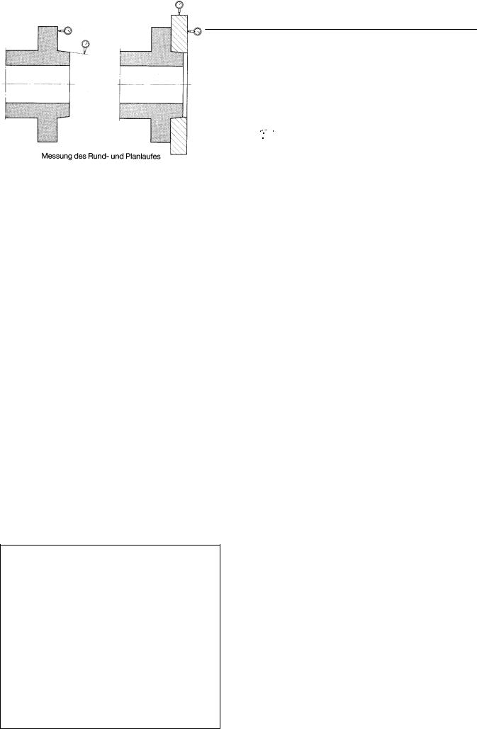
To achieve the highest concentricity of the chuck to spindle, the spindle nose must be checked, with regard to the following points, as shown in the sketch below.
2.1Check the radial and axial run-out of the machine spindle nose, as shown in the sketch below.
2.2Using an H-type straight-edge check the end surface runout. Special care must be taken to ensure that the bores in the end surface are free of burrs and clean.
2.3As a function of the spindle head size, chuck mounting is by either a mounting flange or an intermediate plate. The mounting flange and/or intermediate plate are included in the chuck scope of supply.
When a mounting flange is used it must first be installed on the machine spindle and checked as described under 2.1 and 2.2 to ensure a max. radial run-out of 0.01 mm and a max. axial runout of 0.005 mm. Finally the chuck must be mounted to the flange.
When an intermediate plate is used, the chuck is mounted direct to the machine spindle.
2.4To check chuck radial run-out and axial parallelity, a preci- sion-ground test shaft must be clamped between the face driver and tailstock centers.
2.5The draw bar and draw tube must be made of high-grade tensile steel with a minimum tensile strength of 50 N/mm2. Draw bar and draw tube must be perfectly aligned, this is also applicable to the threads at each end which must be absolutely concentric, relative to each other. To eliminate the difference between the spindle bore and the draw tube outer diameter, guide rings should be fitted, or welded, to the draw bar or the machine spindle provided with guide bushes. The fitted clearance between guide ring and spindle bore should be approx. 0.2 mm.
2.6As a matter of principle, any possible remains of swarf must be carefully removed from the machine spindle before the chuck is installed. In addition, the outer surfaces of the draw tube and the draw bar must be greased.
3.Cylinder, chuck and face driver Installation
3.1Thoroughly clean the cylinder mounting flange and check for radial and face run-out accuracy (see also item 2, point 3).
3.2Engage the thrust tube and thrust rod threads in those of the cylinder piston.
Measurement of radial and axial run-out at spindle nose or spindie flange
3.3Attach the cylinder to the cylinder mounting flange and check radial and face run-out (max. permissible deviation: radial run-out = 0.01 mm, face run-out = 0.005 mm).
3.4Secure the flexible hose lines for clamping and release pressure.
3.5lnstall the leak-off oil hose and the anti-rotation locking device.


 The leak-off oil and coolant return lines must be installed vertically. ModeI RT 38-20.25 micron, pressure filters are to be installed in the lines to prevent the entry of foreign bodies.
The stationary feed housing, anti-rotation locking device must be installed absolutely stress-free. All connecting lines must be of a flexible nature to ensure that no external pressure can be effective at the cylinder housing. Safety guards for rotating components are to be supplied by the machinery manufacturer.
Recommended hydraulic oil:
ISO-HM 32 (2.5-3 °E at 50 °C) or DIN HLP 32
3.6Attach the chuck mounting flange and check face and radial run-out as described under Para 2.
3.7Move both cylinder pistons to their foremost position and determine the precise length of the thrust tube and thrust bar in accordance with the enclosed drawing.
3.8Install the chuck without face driver, top jaws and distributor shaft. For mounting purposes, the chuck piston must be in its rearmost position. In the case of the model KRS-NZ 190 chucks, connection of the chuck piston to the draw tube is established by turning the complete chuck, whereas in the case of the chuck sizes starting with the model KRS-NZ 250 a special key is supplied to facilitate insertion of the draw bush into the draw tube. Finally, the shaft component chuck is pushed onto the chuck mounting flange or, in the case of direct installation, mounted to the machine spindle extension.
3.9Using the 3 securing screws, secure the shaft-component chuck to the chuck flange or the machine spindle extension.
3.10Check chuck radial run-out at the measuring surface "A" (see page 3) max. permissible run-out = 0.02 mm.
3.11Thoroughly grease the distributor shaft and insert it into the chuck piston bore.
3.12Using the 3 alignment wedges, adjust the face driver radial run-out to max. = 0.005 mm (measuring surface 'B') and simultaneously tighten the securing screws to remove all clearance. lt is essential to take great care to ensure that the counter diameter of the basic body (Part 1) is not deformed in the area of the face driver alignment bore.
3.13Install the top jaws in accordance with the jaw markings.
4.Stroke monitoring
The best possibility for the installation of jaw stroke and clamping piston II position monitors (actuation of the face driver central piston unit) is offered at the rear end of the cylinder spindle. The jaw stroke should be such as to ensure that a residual stroke is available for subsequent clamping.
The design of the limit switches and method of limit switch signal transmission varies for the individual machinery models and must, in each case, be specifically matched to the machine controls. The chuck jaw stroke signal and clamping pressure line monitor signal are utilized to initiate spindle rotation release.
4 SMW-AUTOBLOK
 Loading...