

Page 1
USER’S MANUAL - BEDIENUNGSANLEITUNG
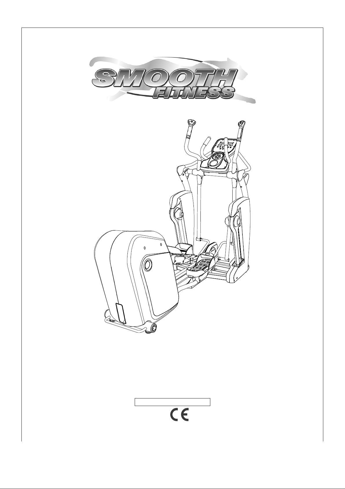
SMOOTH AGILE TRAINER
USER WEIGHT LIMITATION: 350lbs
MAXIMALES BENUTZERGEWICHT: 160 KG
UK: TOLL FREE CUSTOMER SERVICE NUMBER: 0800-097 2100
DE: SERVICENUMBER: +49 (911) 810 59 24
SERIAL NUMBER (found on frame) – SERIENNUMMER (auf Rahmen)
ST-MNL-WT100-SMEU-01
Page 2

2 SMOOTH AGILE TRAINER
INHALTSVERZEICHNIS – TABLE OF CONTENTS
• English P. 03
• Deutsch P. 51
Page 3

www.smoothfitness.co.uk
3
WARNING: To reduce the risk of burns, fire, electric shock, or injury to persons, read the following important
precautions and information before operating the Elliptical Trainer. It is the responsibility of the owner to ensure that all
users of this Elliptical Trainer are adequately informed of all warnings and precautions.
PRECAUTIONS
• Use the Elliptical Trainer only as described in this manual.
• Place on a level surface, with enough space behind it. Do not place the Elliptical Trainer on any surface that
blocks air openings. To protect the floor or carpet from damage, place a mat under the Elliptical Trainer.
• When choosing a location for the Elliptical Trainer make sure that the location and position permit access to a
plug.
• Keep the Elliptical Trainer indoors, away from moisture and dust. Do not put the Elliptical Trainer in a garage
or covered patio, or near water.
• Do not operate the Elliptical Trainer where aerosol products are used or where oxygen is being administered.
• Keep children under the age of 12 and pets away from the Elliptical Trainer at all times.
• The Elliptical Trainer should not be used by persons weighing more than 350 lbs (160 kg)
• Never allow more than one person on the Elliptical Trainer at a time. Wear appropriate exercise clothing when
using the Elliptical Trainer. Do not wear loose clothing that could become caught in the Elliptical Trainer.
Athletic support clothes are recommended for both men and women. Always wear athletic sh oes. Never use
the Elliptical Trainer with bare feet, wearing only stockings, or in sandals.
• When connecting the power cord, plug the power cord into a grounded circuit. No other appliance should be
on the same circuit.
• Always examine your Elliptical Trainer before using to ensure all parts are in working order.
• Never insert any object or body parts into any opening.
• Follow the safety information in regards to plugging in your Elliptical Trainer.
• Keep the power cord away from moving handle bars and do not run the power cord underneath your Elliptical
Trainer. Do not operate the Elliptical Trainer with a damaged or frayed power cord.
• Always unplug the Elliptical Trainer before cleaning and/or servicing. Service to your Elliptical Trainer should
only be performed by an authorized service representative, unless authorized and/or instructed by the
manufacturer. Failure to follow these instructions will void the Elliptical Trainer warranty.
Page 4
4 SMOOTH AGILE TRAINER
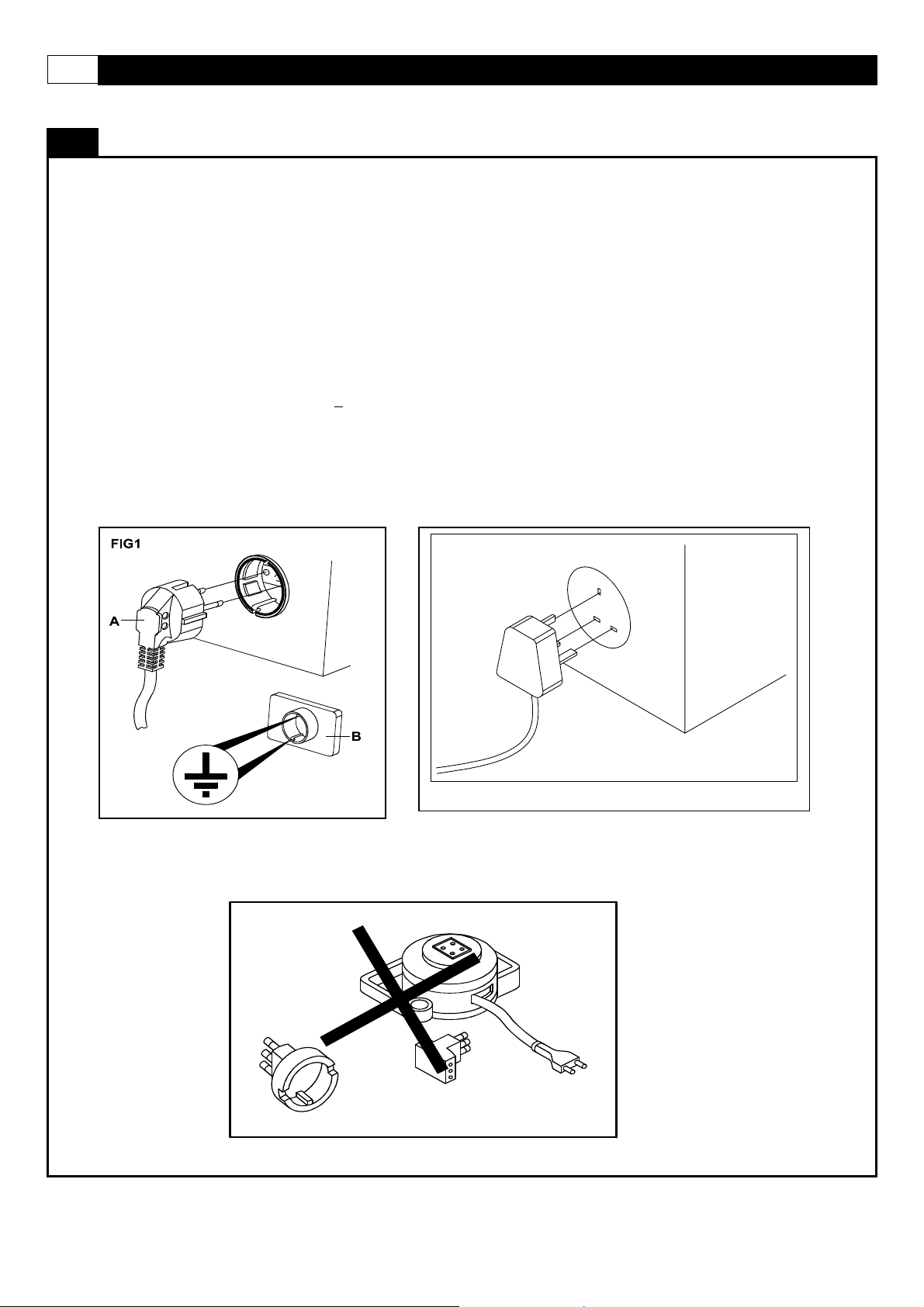
IMPROPER CONNECTION OF THE EQUIPMENT GROUNDING CONNECTOR CAN RESULT IN A RISK OF AN ELECTRIC
SHOCK. CHECK WITH A QUALIFIED ELECTRICIAN OR SERVICE MAN IF YOU ARE IN DOUBT AS TO WHETHER THE
PRODUCT IS PROPERLY GROUNDED. DO NOT MODIFY THE PLUG PROVIDED WITH THE PRODUCT, IF IT WILL NOT FIT
THE OUTLET; HAVE A PROPER OUTLET INSTALLED BY A QUALIFIED ELECTRICIAN.
This Elliptical Trainer can be seriously damaged by sudden voltage cha nges in your home’s electrical power. Voltage spikes,
surges and noise interference can result from weather conditions or from other appliances being turned on or off. To reduce the
possibility of Elliptical Trainer damage, always use a surge protector (not included) with your Elliptica l Trainer. Surge protectors can
be purchased at most hardware stores.
This Elliptical Trainer is provided with two different grounding plugs for Central Europe and United Kin gd om. Please choose the
right one and plug in your Elliptical Trainer.
Please make sure that your local voltage is appropriate for the power requirements of this Elliptical Trainer before you plug it in.
This product is for use with a voltage of 230V+
Do not use a voltage transformer with this product.
Do not use an extension cord with this product when you are not sure if the product is still properly grounded.
The following pictures show the two delivered plugs:
POWER REQUIREMENTS
5%.
Page 5

www.smoothfitness.co.uk
PREASSEMBLY
Open the boxes:
You are now ready to open the boxes of your new equipment. Make sure to inventory all of the parts that are included in the
boxes. Check the Parts List for a full count of the number of parts included for this product to be assembled properly. If you are
missing any parts or have any assembly questions call your local dealer or contact us directly at 08 00-0972100
Gather your tools:
Before starting the assembly of your unit, make sure that you have gathered all the necessary tools you may require
to assemble the unit properly. Having all of the necessary equipment at hand will save time and make the assembly
quick and hassle-free.
Clear your work area:
Make sure that you have cleared away a large enough space to properly assemble the unit. Make sure the space is
free from anything that may cause injury during assembly. After the unit is fully assembled, make sure there is a
comfortable amount of free area around the unit for unobstructed operation.
Invite a friend:
Some of the assembly steps may require heavy lifting. It is recommended that you obtain the assistance of another
person when assembling this product.
User Weight Limitation:
Please note that there is a weight limitation for this product. If you weigh more than 350lbs (160kg) it is not
recommended that you use this product. Serious injury may occur if the user’s weight exceeds the limit
shown here. This product is not intended to support users whose weight exceeds this limit.
5
Page 6
6 SMOOTH AGILE TRAINER
r
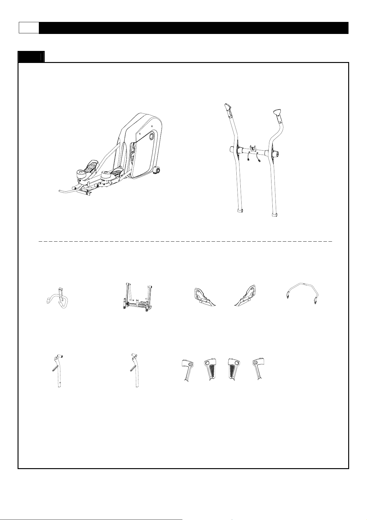
This list identifies the major components you will use to assemble this product.
BOX - A
SUPPLIED COMPONENTS
Main Frame Assembly
Main Frame Assembly Handlebar Assembly
BOX - B
Fixed Handlebar
Upright-Left Upright-Right Pivot Arm Cover
Upright-Left
[ 110 ]
Base Frame
Base Frame Fixed Handlebar
Upright -Right
[ 111 ]
Undercarriage Cover
Undercarriage Cover
Pivot Arm Cover
Handleba
[ 719 / 720 ]
Assembly
Console Support
Console Support
Tube
Page 7
www.smoothfitness.co.uk
This list identifies the major components you will use to assemble this product.
SUPPLIED COMPONENTS
BOX - C
7
Front Side Panel LL - LR
Front Side Panel LL - LR
BOX - D
Front Side Panel
[ 709 / 710 ]
Front Side Panel RL - RR
[ 712 / 711 ]
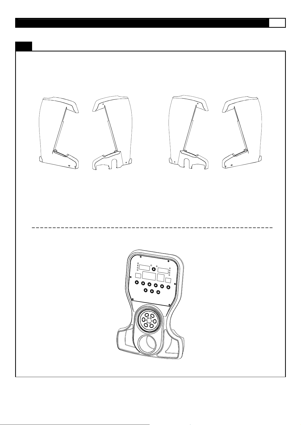
Computer
Computer
Page 8
8 SMOOTH AGILE TRAINER
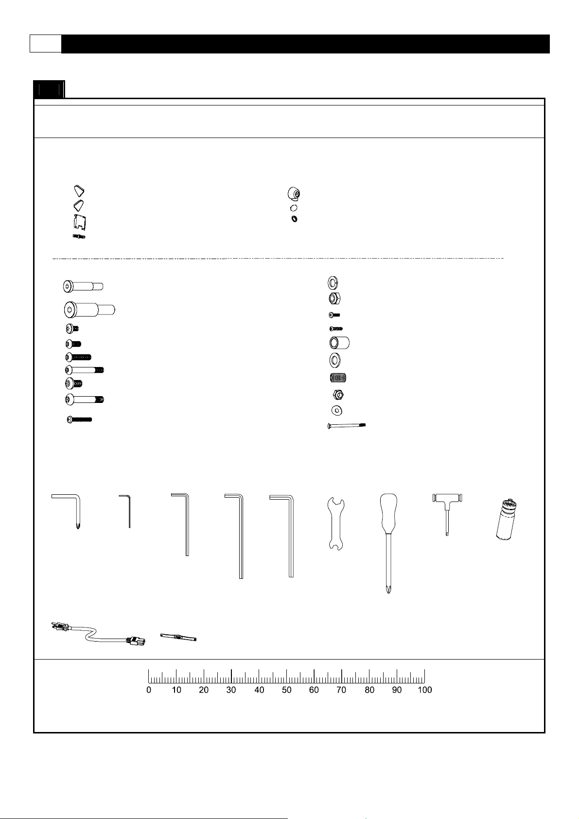
This list identifies the hardware you will use to assemble the product. To help distinguish between the various types
of screws and bolts, use the scale below to measure them and compare them to the sizes listed.
SUPPLIED HARDWARE
BOX - E
701 Upright Side Cover-Left
702 Upright Side Cover-Right
703 Console Back Cover
326 Taper Fixing Insert 4PCS
717 Pivot Cap 2PCS
718 Pivot Side Cap 2PCS
721 Pedal Arm Front Pivot 4PCS
501
502
503
504
505
506
507
508
509
A
Screwdriver-L
(1 piece )
J
(1 piece)
12 x 62 - M10 x 20mm Bolt
20 x 78 - M 14 x 35mm Bolt
M5 x 8mm Screw
M8 x 20mm A llen Head Bolt
M8 x 40mm Allen Head Bolt
M8 x 65mm Allen Head Bolt
M10 x 20mm Allen Head Bolt
M10 x 62 mm Allen Head Bolt
M6x40mmScrew
B
2.5mm
Allenkey
(1 piece)
C
5mm
Allenkey
(1 piece)
K
Chest BeltPower Cord
(1 piece)
2PCS
2PCS
2PCS
4PCS
2PCS
2PCS
4PCS
1PCS
2PCS
DE
8mm6mm
Allenkey
(1 piece) (1 piece)
Allenkey
510
511
512
513
514
515
516 2PCS
517
518
519
F
Wrench
(1 piece)
12 x 20 x 2 Spring Washe r
M10 Nylon Nut
4 x 12mm Screw
4 x 19mm Screw
12 x 18 x 24.5mm Sleev e
12 x 22 x 2 Was her
M5 x 6mm Bolt
M8 Nylon Nut
8x20x1 .5mm Cup Was her 4PCS
M8x105x20 mm Carriage Bolts
G
Slotted
Screwdriver
(1 piece )
H
5mm
AllenWrench
(1 piece)
2PCS
1PCS
10PCS
6PCS
2PCS
2PCS
4PCS
4PCS
Water Bot tle
(1 piece )
I
MILLIMETERS
Page 9

www.smoothfitness.co.uk
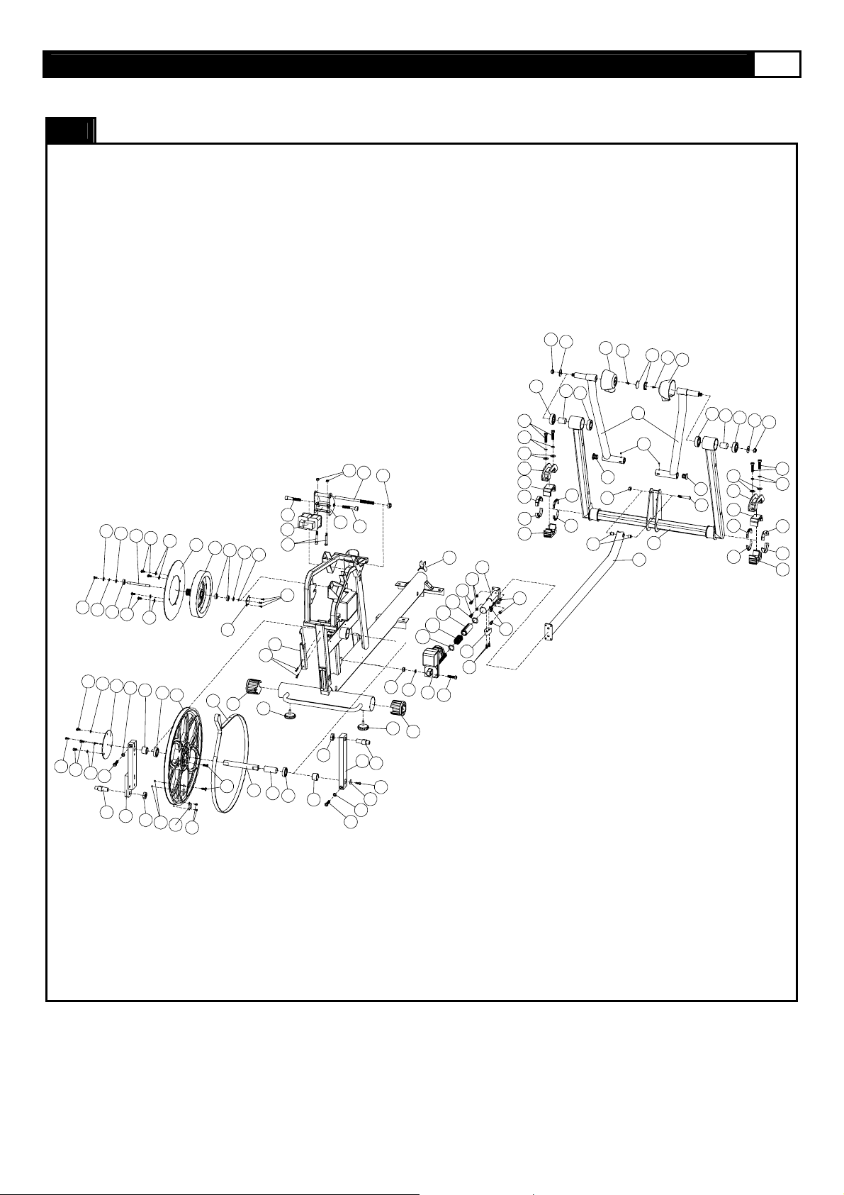
COMPLETE PARTS LIST
Item No. Description Qty. Part No.
100
101 Fixed Handlebar 1 AGILE-101
102 Crossbar 1 AGILE-102
103 Console Support Tube 1 AGILE-103
104 Base Frame 1 AGILE-104
105 Main Frame 1 AGILE-105
106 Pedal Arm-Left 1 AGILE-106
107 Pedal Arm-Right 1 AGILE-107
108 Action Handlebar - Left 1 AGILE-108
109 Action Handlebar - Right 1 AGILE-109
110 Upright-Left 1 AGILE-110
111 Upright-Right 1 AGILE-111
112 Moving Linkage-Left 1 AGILE-112
113 Moving Linkage-Right 1 AGILE-113
114 Incline Frame 1 AGILE-114
115 Incline Transmission Tube-Front 1 AGILE-115
116 Incline Transmission Tube-Back 1 AGILE-116
117 Clamp Bracket 2 AGILE-117
118 Flywheel 1 AGILE-118
119 Tension Wheel Bracket 1 AGILE-119
120 Pedal Swing Arm 2 AGILE-120
121 Hold Base-Front 1 AGILE-121
122 Hold Base-Back 1 AGILE-122
9
200
201 Bearing 6004 4 AGILE-201
202 Bearing 6005 2 AGILE-202
203 Bearing 6300 6 AGILE-203
204 Bearing 6804 4 AGILE-204
205 Bearing 2203 2 AGILE-205
206 Bearing 6205 4 AGILE-206
207 Bearing 608zz 8 AGILE-207
208 Action Handlebar Shaft Bushing 2"x38-20 2 AGILE-208
209 Action Handlebar Shaft Bushing 2"x38-9 2 AGILE-209
210 Elector-magnetic System 1 AGILE-210
211 Oil-Impregnated Bearing 2 AGILE-211
212 Clamp Bushing- Top 2 AGILE-212
213 Clamp Bushing- Bottom 2 AGILE-213
Page 10

10 SMOOTH AGILE TRAINER
Item No. Description Qty. Part No.
COMPLETE PARTS LIST
214 Belt 1 AGILE-214
215 Aluminum Disk 1 AGILE-215
216 Crank 1 AGILE-216
217 Crank 25x186.7 1 AGILE-217
218 Crank Disk Axle 1 AGILE-218
219 Wheel 2 AGILE-219
220 Pedal Buffer Set 2 AGILE-220
221 Level Adjuster 2 AGILE-221
222 Crank Disk 1 AGILE-222
224 Action Handlebar End Cap 2 AGILE-224
225 Hand Pulse Sensor Cover 2 AGILE-225
226 Oval Tube Cap 2 AGILE-226
227 Hand Pulse Sensor Back Cover 2 AGILE-227
228 Fixed Handlebar Foam Grip 2 AGILE-228
229 Electro-magnetic System Bracket 1 AGILE-229
230 Flywheel Axle Fixing Plate 1 AGILE-230
231 Speed Sensor Base 1 AGILE-231
232 Pedal Support Base 2 AGILE-232
233 Pedal Fixing Base 2 AGILE-233
234 Crank Disk Oval Cap 1 AGILE-234
235 Switch Fascia 1 AGILE-235
238 Bearing 2201 2 AGILE-238
239 5/16" Cable Tie 1 AGILE-239
240 1/8" Cable Tie 1 AGILE-240
241 3/8" Cable Tie 4 AGILE-241
242 Wheel Bushing 4 AGILE-242
243 Bearing 6000 3 AGILE-243
244 Self-adhesive Wire Clip 1 AGILE-244
249 3/16" Cable Tie 1 AGILE-249
250 1/4" Cable Tie 9 AGILE-250
251 Hand Grip Gasket 2 AGILE-251
252 Bearing Support Tube 1 AGILE-252
253 Rear Shroud Holder 1 AGILE-253
300
302 Rear Shroud-Left 1 AGILE-302
303 Rear Shroud-Right 1 AGILE-303
304 Rear Side Panel-Left 1 AGILE-304
305 Rear Side Panel-Right 1 AGILE-305
Page 11

www.smoothfitness.co.uk
11
Item No. Description Qty. Part No.
COMPLETE PARTS LIST
306 Switch Plate 1 AGILE-306
307 Pedal 2 AGILE-307
308 Toe Cap 2 AGILE-308
309 Pedal Soft Cushion 2 AGILE-309
310 Pedal Bushing Cover-Left 2 AGILE-310
311 Pedal Bushing Cover-Right 2 AGILE-311
312 Console Housing - Upper 1 AGILE-312
313 Console Housing – Bottom 1 AGILE-313
314 Console Plastic Cover 1 AGILE-314
315 Rubber Strip-4 4 AGILE-315
316 Rubber Strip-3 4 AGILE-316
317 Rubber Strip-2 4 AGILE-317
318 Rear Shroud Plug-1 2 AGILE-318
319 Rear Shroud Plug-2 2 AGILE-319
320 Rubber Strip-1 4 AGILE-320
321 Cable Plug 2 AGILE-321
322 Incline Transmission Tube Holder 1 AGILE-322
323 Moving Linkage Bushing 4 AGILE-323
324 Control Board Cover 1 AGILE-324
325 Pedal Swing Arm Cap 2 AGILE-325
326 Taper Fixing Insert 35 AGILE-326
327 Support Lump 1 AGILE-327
328 Oblong Cushion 2 AGILE-328
329 Circular Cushion 2 AGILE-329
330 Rubber Cushion – Front 2 AGILE-330
331 Rubber Cushion – Rear 2 AGILE-331
332 Fixing Insert 22 AGILE-332
333 Fixing Insert-Metal Inside 7 AGILE-333
336 Action Handlebar Front Cover 4 AGILE-336
337 Action Handlebar Cover 2 AGILE-337
338 Elbow-Left 2 AGILE-338
339 Elbow-Right 2 AGILE-339
340 Button 1 AGILE-340
341 Taper Fixing Insert-Metal Inside 3 AGILE-341
Page 12

12 SMOOTH AGILE TRAINER
COMPLETE PARTS LIST
Item No. Description Qty. Part No.
400
402 25 x 10 x 55 - M10 x 15mm Bolt 2 AGILE-402
403 M5 x 8mm Allen Head Bolt 7 AGILE-403
404 M6 x 12mm Allen Head Bolt 11 AGILE-404
405 M8 x 15mm Allen Head Bolt 23 AGILE-405
406 M8 x 25mm Allen Head Bolt 2 AGILE-406
407 M10 x 20mm Allen Head Cap Bolt 4 AGILE-407
408 M10 x 40mm Allen Head Bolt 1 AGILE-408
409 M4 X 40mm Allen Head Cap Bolt 1 AGILE-409
410 M8 x 50mm Allen Head Cap Bolt 2 AGILE-410
411 M10 x 40mm Allen Head Cap Bolt 2 AGILE-411
412 M12 x 70mm Allen Head Cap Bolt 2 AGILE-412
414 M8 x 20mm Bolt 6 AGILE-414
415 M3 x 8mm Screw 2 AGILE-415
416 M8 x 65mm Allen Head Cap Bolt 2 AGILE-416
417 M6 x 12mm Allen Head Cap Bolt 2 AGILE-417
418 M8 x 16mm Allen Head Cap Bolt 4 AGILE-418
419 M8 x 90mm Allen Head Bolt 4 AGILE-419
421 M8 Nylon Nut 8 AGILE-421
422 M10 Nylon Nut 3 AGILE-422
423 M14 Nylon Nut 3 AGILE-423
424 M8 Blind Nut 2 AGILE-424
425 M6 x 15mm Screw 2 AGILE-425
426 3/4" x 16 Nut 2 AGILE-426
427 Flywheel Axle 1 AGILE-427
428 10 x 36mm Shaft 2 AGILE-428
429 12 x 210 - M14 x 70mm Shaft 1 AGILE-429
430 Bushing 12 x 60 4 AGILE-430
431 M4 x 15mm Screw 2 AGILE-431
432 4 x 12mm Round Head Screw 8 AGILE-432
433 Action Handlebar Shaft 1 AGILE-433
Page 13

www.smoothfitness.co.uk
13
Item No. Description Qty. Part No.
COMPLETE PARTS LIST
435 Crank Axle Bushing 2 AGILE-435
436 M10 C Clip 6 AGILE-436
437 M12 C Clip 2 AGILE-437
438 M42 C Clip 2 AGILE-438
439 10 x 18 x T1.0 Fiber Washer 2 AGILE-439
440 15 x 8 x T2.0 Spring Washer 11 AGILE-440
441 10 x 16 x T2.0 Spring Washer 7 AGILE-441
442 20 x 6 x T2.0 Washer 3 AGILE-442
443 32 x 6 x T2.0 Washer 1 AGILE-443
444 35 x 14 x T2.0 Washer 2 AGILE-444
445 10 x 18 x T5.1 Washer 4 AGILE-445
446 M3 x 16mm Screw 2 AGILE-446
447 M3 x 10mm Screw 18 AGILE-447
448 4 x 12mm Screw 39 AGILE-448
449 M2 x 6mm Screw 8 AGILE-449
450 4 x 12mm Coarse Thread Screw 23 AGILE-450
451 M32 C Clip 2 AGILE-451
452 M4 x 45mm Screw 2 AGILE-452
453 M4 x 8mm Screw 4 AGILE-453
454 7 x 12 - M5 x 5mm Pin Nut 4 AGILE-454
456 10 x 23 x T2.0 Washer 4 AGILE-456
457 6 x 10 x 1 Spring Washer 2 AGILE-457
458 28.6 x 35.5 Bushing 2 AGILE-458
459 12 x 20 x 0.5 Washer 2 AGILE-459
460 12 x 20 x 2 PU Washer 2 AGILE-460
461 4 x 12mm Self Tapping Screw 6 AGILE-461
462 M8 x 16mm Bolt 8 AGILE-462
463 4 x 12mm Screw-cone point 4 AGILE-463
464 4 x 30mm Screw 2 AGILE-464
465 M4 Nut 2 AGILE-465
500
501 12 x 62 - M10 x 20mm Bolt 2 AGILE-501
502 20 x 78 - M14 x 35mm Bolt 2 AGILE-502
503 M5 x 8mm Screw 2 AGILE-503
504 M8 x 20mm Allen Head Bolt 4 AGILE-504
505 M8 x 40mm Allen Head Bolt 2 AGILE-505
506 M8 x 65mm Allen Head Bolt 2 AGILE-506
507 M10 x 20mm Allen Head Bolt 4 AGILE-507
508 M10 x 62mm Allen Head Bolt 1 AGILE-508
509 M6 x 40mm Screw 2 AGILE-509
Page 14

14 SMOOTH AGILE TRAINER
COMPLETE PARTS LIST
Item No. Description Qty. Part No.
510 12 x 20 x 2 Spring Washer 2 AGILE-510
511 M10 Nylon Nut 1 AGILE-511
512 4 x 12mm Screw 10 AGILE-512
513 4 x 19mm Screw 6 AGILE-513
514 12 x 18 x 24.5mm Sleeve 2 AGILE-514
515 12 x 22 x 2 Washer 2 AGILE-515
516 M5 x 6mm Bolt 2 AGILE-516
517 M8 Nylon Nut 4 AGILE-517
518 8 x 20 x 1.5mm Cup Washer 4 AGILE-518
519 M8 x 105 x 20mm Carriage Bolt 4 AGILE-519
600
601 Speed Sensor 1 AGILE-601
602 Magnetic Sensor 1 AGILE-602
603 Power Switch 1 AGILE-603
604 Power Breaker 1 AGILE-604
605 Power Insert Set 1 AGILE-605
606 Receiver 1 AGILE-606
607 Transformer 1 AGILE-607
608 Computer PC Board 1 AGILE-608
609 Elevation Motor 1 AGILE-609
610 Control Board 1 AGILE-610
611 Button Sticker 1 AGILE-611
612 Overlay 1 AGILE-612
613 Elector-magnetic Wire 1 AGILE-613
614 Power Connect Wire 3 AGILE-614
615 8Pin Power Wire-Top 200mm 1 AGILE-615
616 8Pin Power Wire-Upper 1000mm 1 AGILE-616
617 8Pin Power Wire-Middle 900mm 1 AGILE-617
618 8Pin Power Wire-Lower 800mm 1 AGILE-618
619 8Pin Power Wire-Bottom 2700mm 1 AGILE-619
620 3C Power Wire 1000mm 1 AGILE-620
621 Hand Pulse Sensor Wire-Top 350mm 2 AGILE-621
622 Hand Pulse Sensor Wire-Upper 620mm 2 AGILE-622
623 Hand Pulse Sensor Wire-Lower 650mm 2 AGILE-623
624 Receiver Wire 350mm 1 AGILE-624
626 Control Board Connect Wire 250mm 1 AGILE-626
Page 15

www.smoothfitness.co.uk
15
COMPLETE PARTS LIST
Item No. Description Qty. Part No.
700
701 Upright Side Cover-Left 1 AGILE-701
702 Upright Side Cover-Right 1 AGILE-702
703 Console Back Cove r 1 AGILE-703
704 Pivot Arm Cover-LL 1 AGILE-704
705 Pivot Arm Cover-LR 1 AGILE-705
706 Pivot Arm Cover-RR 1 AGILE-706
707 Pivot Arm Cover-RL 1 AGILE-707
708 Pivot Arm Insert 2 AGILE-708
709 Front Side Panel-LL 1 AGILE-709
710 Front Side Panel-LR 1 AGILE-710
711 Front Side Panel-RR 1 AGILE-711
712 Front Side Panel-RL 1 AGILE-712
713 Front Side Frame-LL 1 AGILE-713
714 Front Side Frame-LR 1 AGILE-714
715 Front Side Frame-RR 1 AGILE-715
716 Front Side Frame-RL 1 AGILE-716
717 Pivot Cap 2 AGILE-717
718 Pivot Side Cap 2 AGILE-718
719 Undercarriage Cover-Left 1 AGILE-719
720 Undercarriage Cover-Right 1 AGILE-720
721 Pedal Arm Front Pivot Cover 4 AGILE-721
A Screwdriver-L 1 AGILE-A
B 2.5mm Allen Key 1 AGILE-B
C 5mm Allen Key 1 AGILE-C
D 6mm Allen Key 1 AGILE-D
E 8mm Allen Key 1 AGILE-E
F 14 x 17 Wrench 1 AGILE-F
G Slotted Screwdriver 1 AGILE-G
H 5mm Allen Wrench 1 AGILE-H
I Water Bottle 1 AGILE-I
J Power Cord 1 AGILE-J
K Chest Belt 1 AGILE-K
Page 16
16 SMOOTH AGILE TRAINER
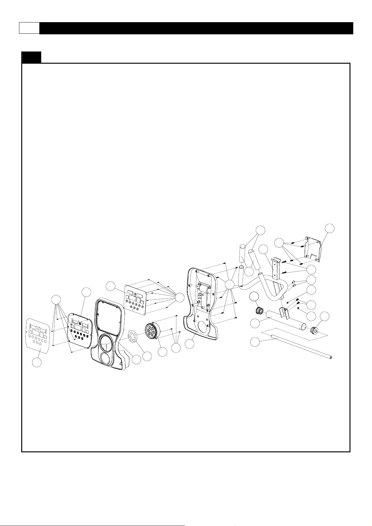
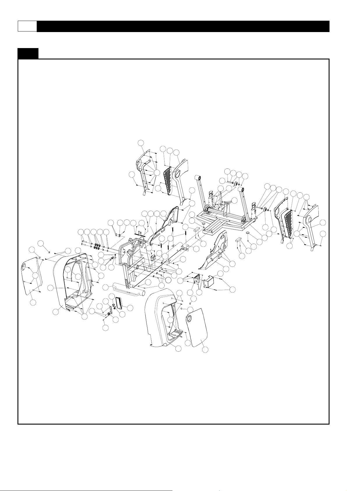
MOST OF THE PARTS SHOWN HERE HAVE BEEN PRE-ASSEMBLED.
PARTS DIAGRAM
224
703
612
447
314
608
312
611
340
450
449
313
450
228
208
102
433
101
326
509
424
321
504
321
208
Page 17
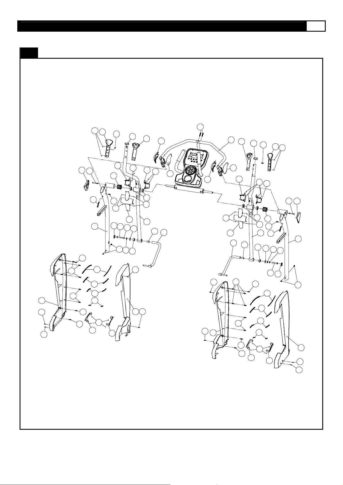
MOST OF THE PARTS SHOWN HERE HAVE BEEN PRE-ASSEMBLED.
PARTS DIAGRAM
www.smoothfitness.co.uk
17
709
512
513
332
332
332
701
326
326
506
416
713
447
110
315
316
317
320
447
227
714
209
504
721
326
448
336
501
504
515
510
337
251
432
238
451
513
710
513
225
336
201
448
108
514
432
338
112
339
505
513
338
513
712
448
337
103
339
113
332
332
336
225
514
251
326
201
238
432
448
317
109
316
315
326
336
451
209
320
504
416
501
515
227
721
510
447
506
702
111
504
326
332
716
447
715
512
513
711
Page 18
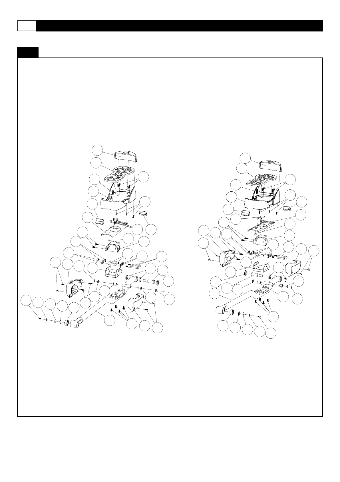
18 SMOOTH AGILE TRAINER
MOST OF THE PARTS SHOWN HERE HAVE BEEN PRE-ASSEMBLED.
417
PARTS DIAGRAM
414
207
421
448
310
437
457
442
438
326
205
331
232
233
308
309
406
307
459
323
106
421
430
405
405
404
450
220
207
311
330
204
323
419
502
721
460
448
310
448
326
721
107
414
421
502
205
307
307
331
233
406
405
460
438
308
309
430
442
457
207
405
417
204
323
404
450
450
421
220
419
330
232
311
459
437
448
Page 19
MOST OF THE PARTS SHOWN HERE HAVE BEEN PRE-ASSEMBLED.
404
PARTS DIAGRAM
442
439
427
405
440
404
436
243
405
440
405
440
234
441
435
202
222
405
440
411
434
217
426
465
602
421
429
423
412
210
218
436
410
403
122
464
221
253
202
215
118
243
439
230
214
226
414
431
229
412
322
418
116-1
116-2
116-3
116-1
327
422
441
609
408
221
226
426
216
434
404
411
443
441
435
456
117
212
245
246
19
206
444
423
407
441
248
247
213
www.smoothfitness.co.uk
423
444
717
503
718
503
717
206
458
206
407
441
456
117
212
248
247
213
116
440
440
418
425
245
246
211
120
516
325
511
114
115
325
508
206
458
Page 20
20 SMOOTH AGILE TRAINER
MOST OF THE PARTS SHOWN HERE HAVE BEEN PRE-ASSEMBLED.
PARTS DIAGRAM
704
450
708
705
319
304
332
318
448
302
448
463
463
252
402
333
445
415
203
333
403
445
448
601
333
446
105
403
235
422
403
231
603
605
119
604
409
306
512
121
463
249
448
250
324
219
720
436
448
512
452
428
448
242
461
436
328
461
329
104
219
436
512
428
436
242
707
450
708
326
450
326
706
512
326
450
719
240448
512
507
326
607
241
250
241
241
448
332
448
448
454
239
328
610
319
512
326
329
461
461
244
453
318
448
303
305
Page 21
PARTS DIAGRAM
MOST OF THE PARTS SHOWN HERE HAVE BEEN PRE-ASSEMBLED.
615
www.smoothfitness.co.uk
21
621
624
606
340
620
607 609
619
626
617
623
615
623
616
623
622
617
614
620
613
614
601
620
613
620
619
613
618
619
Page 22
22 SMOOTH AGILE TRAINER
ASSEMBLY
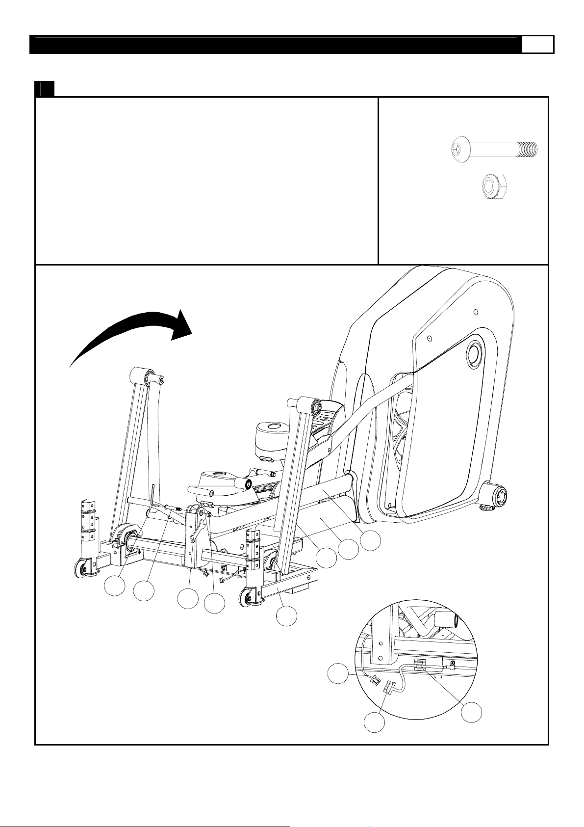
STEP 1: Connect the Main Frame to Base Frame
(A) Rotate Incline Frame (114) up to vertical position.
(B) Place cardboard block under Main Frame tube to provide clearance to
position Base Frame (104) for assembly.
(C) Position Base Frame (104) under mounting bracket of the Main Frame
(105) and align the 4 hole bolt pattern.
(D) Remove cardboard block and lower Main Frame (105) onto Base Frame
(104). Mounting Brackets should seat fully onto Base Frame (104).
Secure using four M10 x 20mm Allen Head Bolts (507).
114
507 X4
507
105
104
A
B
619
c
507
618
104
Mounting Brackets
105
Page 23
ASSEMBLY
www.smoothfitness.co.uk
23
STEP 2: Connect the Incline Transmission Tube
(A) Remove the Incline Transmission Tube Holder (322), and discard.
(B) Rotate the Incline Frame (114) to align the bolt holes with the mating bolt
holes in the Incline Transmission Tube-Front (115).
(C) Assemble the Incline Transmission Tube-Front (115) to the Base Frame
(104) with M10 x 62mm Allen Head Bolt (508) and M10 Nylon Nut (511)
by 6mm Allen Key (D) and Wrench (F).
(D) Connect the 8Pin Power Wire-Lower (618) to the 8Pin Power Wire
-Bottom (619) , and fixed the wire into the Self-adhesive Wire Clip (244).
508 X1
511 X1
115
105
114
D
508
F
511
104
619
FIG 2
618
244
Page 24
24 SMOOTH AGILE TRAINER
ASSEMBLY
STEP 3: Assemble the Undercarriage Covers
NOTE:THE UNDERCARRIAGE COVER-LEFT(719) FITS OVER THE 8PIN
POWER WIRE-LOWER (618). BE CAREFUL NOT TO DISCONNECT
THE WIRE WHEN ASSEMBLING THE UNDERCARRIAGE COVER
-LEFT (719).
(A) Lift the Pedal Arm and assemble the Undercarriage Cover-Left (719) to the
Base Frame (104), and secure using four 4 x 12 Screws (512).
(B) Repeat the above procedure to assemble the right side.
512 X4
512
720
104
107
106
618
105
512
719
Page 25
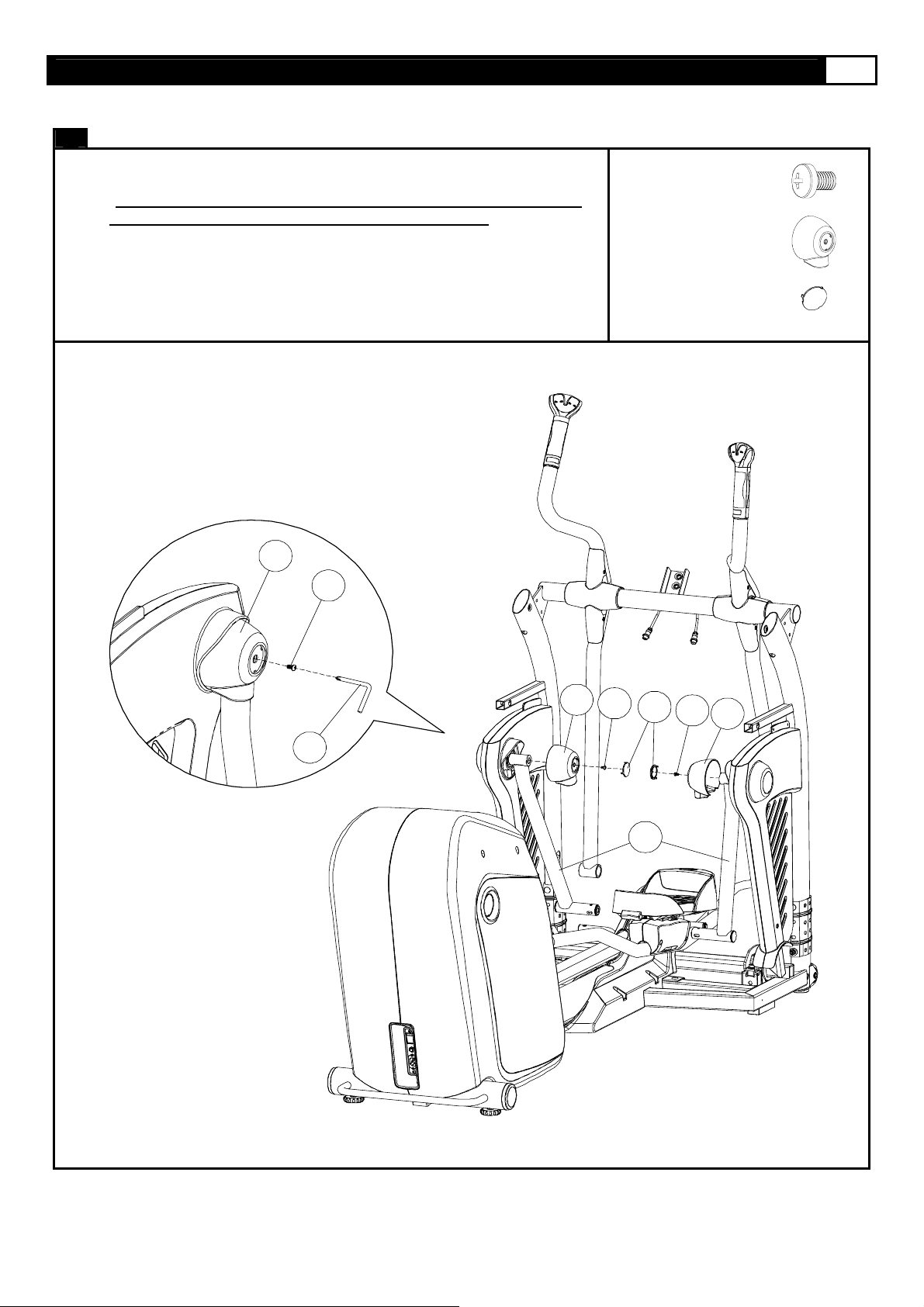
STEP 4: Assemble the Upright
(A) Assemble the Upright-Left (110) and Upright-Right (111) to the
Handlebar assembly and secure using two M8 x 56mm Allen Head Bolts
(506). Do not completely tighten M8 x 56mm Allen Head Bolts until
step C.
(B) Place the Upright Assembly to the Base Frame (104) and secure with
four M8 x 105 x 20mm Carriage Bolts (519), four M8 x 20 x 1.5mm Cup
Washers (518) and N8 Nylon Nuts (517).
(C) Tighten M8 x 56mm Allen Head Bolt (506)
(D) Connect the 8Pin Power Wire-Lower (618) to the 8Pin Power Wire-
Middle (617).
www.smoothfitness.co.uk
506 X2
517 X4
518 X4
519 X4
25
506
111
109
102
108
110
506
517
519
111
518
617
518
517
519
519
110
519
517
518
104
618
Page 26
26 SMOOTH AGILE TRAINER
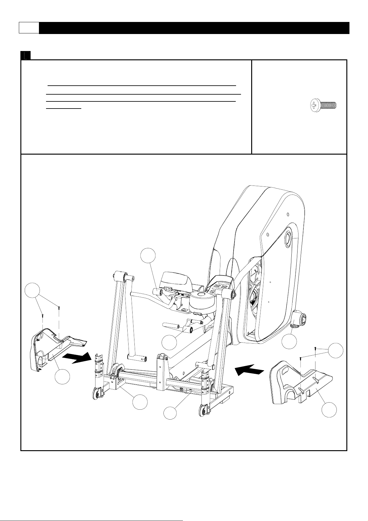
STEP 5: Attach the Pivot Arm Covers
(A) Thread the free end of the Pedal Swing Arm (120) through the hole in
(B) Assemble the Pivot Arm Cover-RR (706) and the Pivot Arm Cover (707)
(C) Repeat the above procedure to assemble the left side.
ASSEMBLY
the Pivot Arm Cover-RL (707) and maneuver the Pivot Arm Cover-RL
(120) to it’s final upright position. See the illustrations in STEP1, STEP2,
and STEP3.
using the press-fit pins and secure to the frame using two 4 x 12mm
Screws (512).
STEP1
120
707
512 X4
STEP2
707
120
STEP3
707
120
706
512
707
120
705
512
114
704
512
Page 27
STEP 6: Assemble the Pivot Cap
NOTE: ALIGN THE 3 SNAP FIT TABS ON THE PEDAL SIDE CAPS (718)
WITH THE 3 SNAP FIT ON THE PEDAL CAPS (717).
(A) Assemble the Pivot Cap (717) to the Pedal Swing Arm (120) and secure
using the M5 x 8mm Screw (503).
(B) Press the Pedal Side Cap (718) to the Pedal Cap (717).
www.smoothfitness.co.uk
503 X2
717 X2
718 X2
27
717
A
503
717
503
718
120
503
717
Page 28
28 SMOOTH AGILE TRAINER
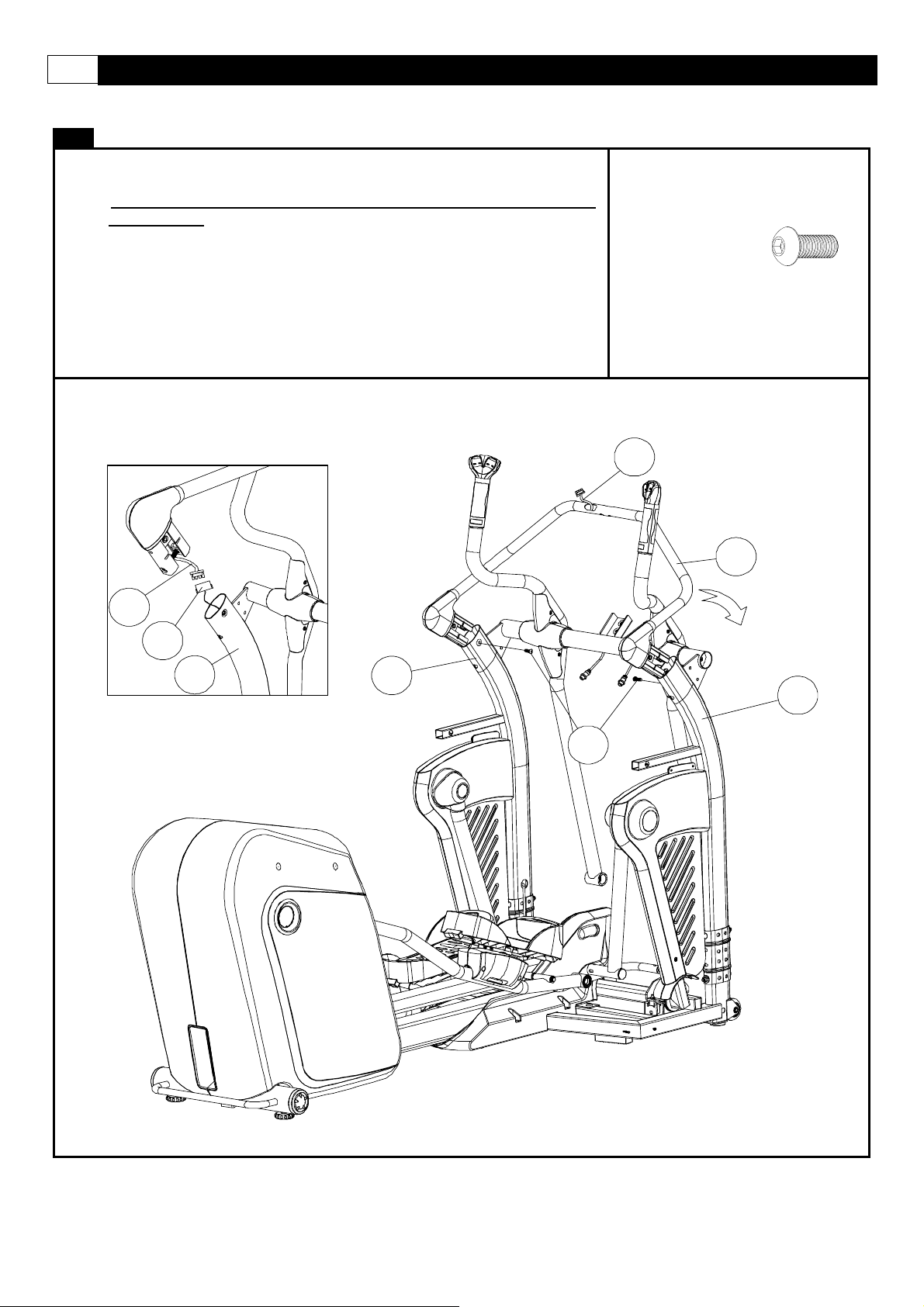
STEP 7: Assemble the Console Support Tube
NOTE: INSERT BOTH ENDS OF THE CONSOLE SUPPORT TUBE AT THE
SAME TIME.
(A) Connect the 8Pin Power Wire-Upper (616) to the 8Pin Power Wire-Middle
(617).
(B) Assemble the Consol Support Tube (103) to the Upright and Secure using
the M8 x 20mm Allen Head Bolt (504).
504 X2
FIG 3
616
617
110
616
103
110
111
504
Page 29
ASSEMBLY
STEP 8: Assemble the Fixed Handlebar
(A) Assemble the Fixed Handlebar (101) to the Console Support Tube (103)
and Crossbar (102).
(B) Secure the Fixed Handlebar (101) to the Crossbar (102) with two
M8 x 20mm Allen Head Bolts (504).
(C) Secure the Fixed Handlebar (101) to the Console Support Tube (103 )
with two M8 x 40mm Allen Head Bolts (505).
101
103
www.smoothfitness.co.uk
504 X2
505 X2
29
102
101
505
103
504
102
Page 30
30 SMOOTH AGILE TRAINER
ASSEMBLY
STEP 9: Tighten all Bolts
(A) Tighten the M8 x 65mm Allen Head Cap Bolt by 6mm Allen Key (D) as show in STEP1.
(B) Tighten the M8 x 105 x 20mm Allen Head Bolt (504) by Wrench (F) as show in STEP2.
STEP 2
STEP1
416
STEP 1
STEP 1
D
STEP 2
F
Page 31

ASSEMBLY
STEP 10: Assemble Upright Side Covers
(A) Press the Upright Side Cover-Left (701) and Upright Side Cover-Right
into the Upright sides.
www.smoothfitness.co.uk
701 X1
702 X1
31
701
110
702
111
Page 32

32 SMOOTH AGILE TRAINER
ASSEMBLY
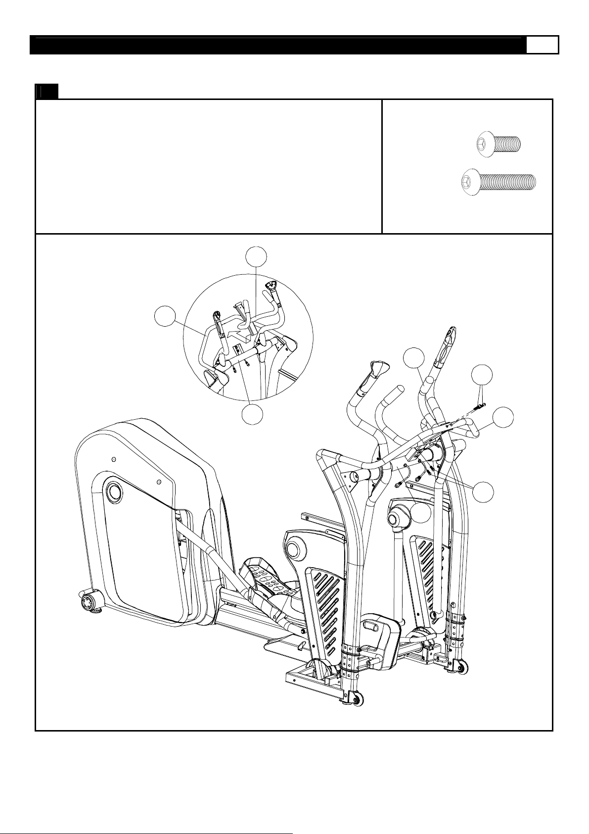
STEP 11: Connect the Pedal Arm to the Pedal Swing Arm
(A) Slide the 20 x 78-M14 X 35mm Bolt (502) through the Pedal Arm-Right
(107) and Pedal Swing Arm (120) the secure by 8mm Allen Key (E).
(B) Repeat the above procedure to assemble the left side.
502 X2
120
107
502
E
Page 33

ASSEMBLY
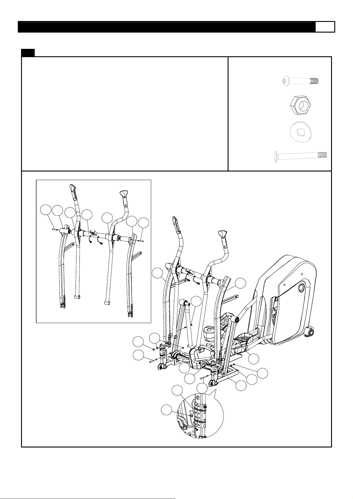
STEP 12: Connect the Moving Linkage
(A) Connect the Action Handlebar-Right (109) to the Moving Linkage-Right
(113) and secure using the 12 x 62-M10 x 20mm Bolt (501), 12 x 2 x 2mm
Spring Washer (510), 12 x 22 x 2mm Washer (515), and 12 x 18 x 24.5
Sleeve (514) by 6mm Allen Key (D), as show in FIG1.
(B). Repeat the above procedure to assemble the left side.
www.smoothfitness.co.uk
501 X2
510 X2
514 X2
515 X2
33
109
501
113
510
515
514
D
FIG 1
515
501
113514
Page 34

34 SMOOTH AGILE TRAINER
ASSEMBLY
STEP 13: Assemble the Pedal Arm Front Pivot Covers
(A) Press the Pedal Arm Front Pivot Cover (721) into the ends of the Action
Handlebar-Right (109) and Pedal Arm-Right (107).
(B) Repeat the above procedure on the left side.
721 X4
109 107
721
108
721
Page 35

ASSEMBLY
STEP 14: Tighten Set Screws
(A) Secure the M5 x 6mm Screw (516) to the
Pedal Swing Arm (120) using the
2.5mm Allen Key (B).
516 X2
www.smoothfitness.co.uk
B
516
35
120
516
120106
B
Page 36

36 SMOOTH AGILE TRAINER
ASSEMBLY
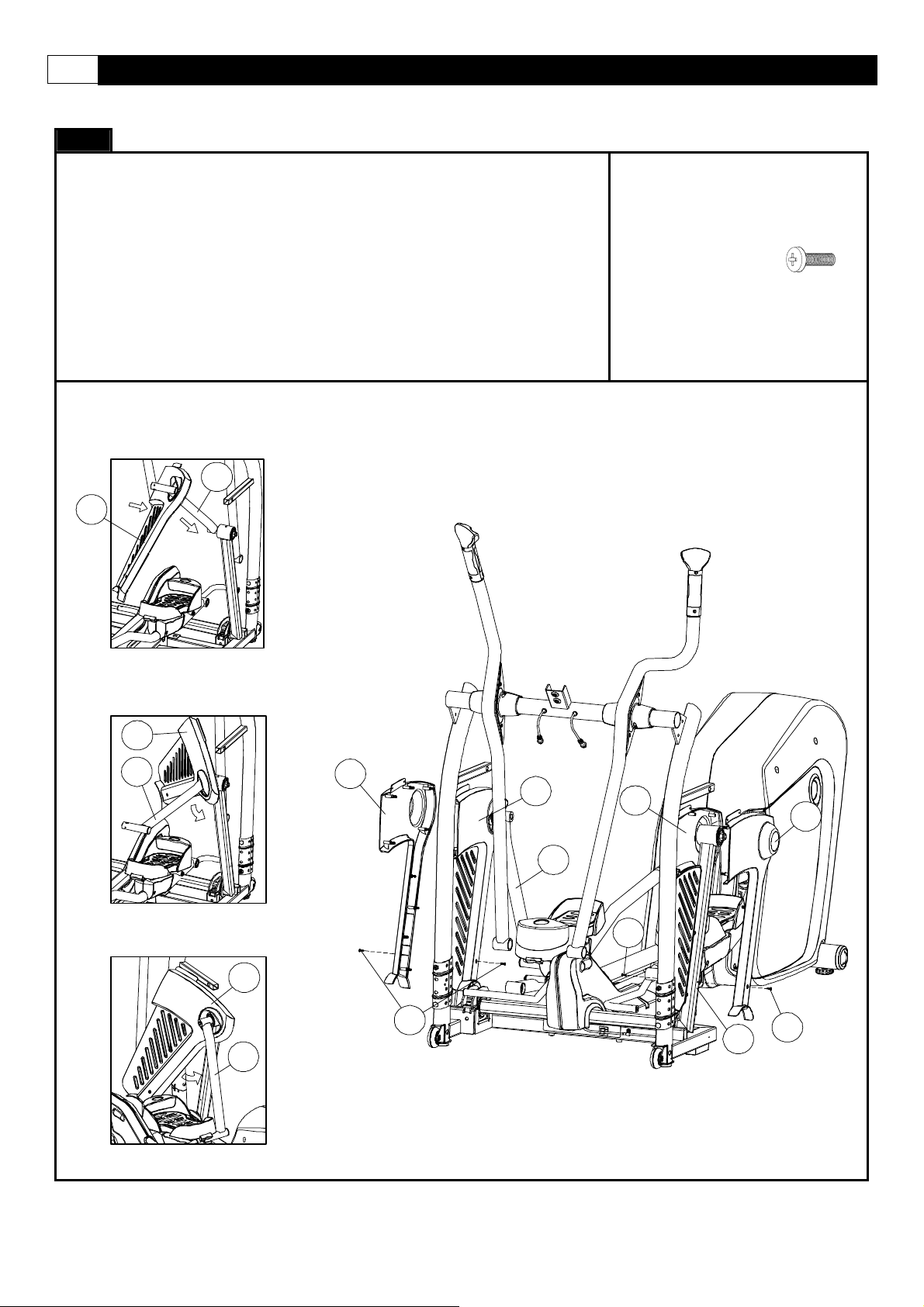
STEP 15: Assemble the Front Side Panels
NOTE: THERE ARE 2 HOLES IN THE FRAME COMPONENTS THROUGH
WHICH THE INSIDE AND OUTSIDE PLASTIC PANELS CONNECT
TO EACHOTHER. USE THESE HOLES AS REFERENCES TO
CORRECTLY POSITION THE PLASTIC PANELS.
(A) Assemble the Front Side Panel-LL (709) and Front Side Panel-LR (710)
to the left Upright and secure using one 4 x 12 Screw (512) and three
4 x 19mm Screws (513).
(B) Repeat the above procedure to assemble the right side.
512 X2
513 X6
513
512
711
111
110
710
513
712
513
709
512
513
Page 37

ASSEMBLY
STEP 16: Assemble the Console
NOTE: BE SURE TO PUSH THE WIRES INTO THE CONSOLE BEFORE
YOU SECURE TO THE FRAME.
(A) Connect the 8Pin Power Wire-Top (615) to the 8Pin Power Wire-Upper (616)
as show in FIG1.
(B) Assemble the Computer (312) to the Console Support Tube (103) and secure
using two M6 x 40mm Screws (509).
(C) Connect the Hand Pulse Sensor Wire-Upper (622) to Computer (312) as
show in FIG2.
FIG 1
www.smoothfitness.co.uk
509 X2
37
103
FIG 2
312
615
616
312
509
622
Page 38

38 SMOOTH AGILE TRAINER
ASSEMBLY
STEP 17: Assemble Console Back Cover
(A) Assemble the four Taper Fixing Inserts (326) to the Console Back Cover
(703).
(B) Assemble the Console Back Cover (703) to the Computer (312).
312
326 X4
703
326
Page 39

www.smoothfitness.co.uk
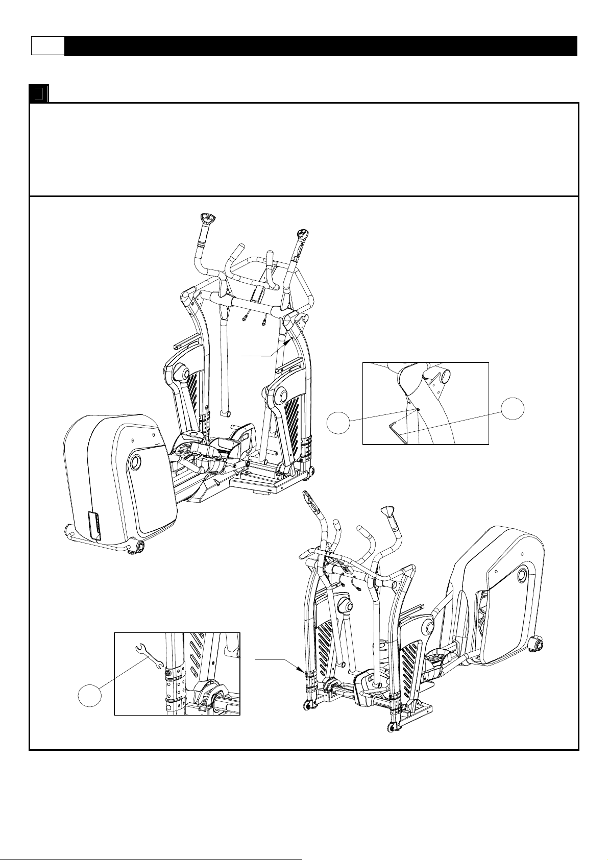
LEVEL ADJUSTMENT
LEVEL ADJUSTMENT:
To adjust the levelers follow these instructions:
You will need someone to help you with this procedure, as you will need to tip, the
adjusting the levelers
Tip the
be screwed either in or out to level the trainer. Repeat for the other side. It may help to use a bubble level when
adjusting the level on your
AGILE Dynamic Motion Trainer to the left/right. You will then see the LEVEL ADJUSTERS. These will need to
AGILE Dynamic Motion Trainer.
AGILE Dynamic Motion Trainer while
39
LEVEL ADJUSTMENT
SERIAL NUMBER LOCATION
Page 40

40 SMOOTH AGILE TRAINER
LITE-TOUCH CONTROL:
LITE-TOUCH CONTROL OPERATION
The Intensity Level and Motion Level can be controlled using the Lite-Touch controls on the hand grip s of the
action handlebars. As the illustration indicates, the right Lite-Touch Controller controls the Motion Level and the
left Lite-Touch Controller controls the Intensity Level. You can see the corresponding readouts on the console
follow this same orientation.
To use the Lite-Touch Controls, simply start a program or select START and begin your wo rk out. To increase
either the Motion Level or the Intensity Level, move your thumb to the thumb groove with the “+” indicator. If you
hold your thumb in the thumb groove the level will continue to increase until you remove your thumb. To decrease
the level simply place your thumb in the groove marked with the “-“ indicator.
Page 41

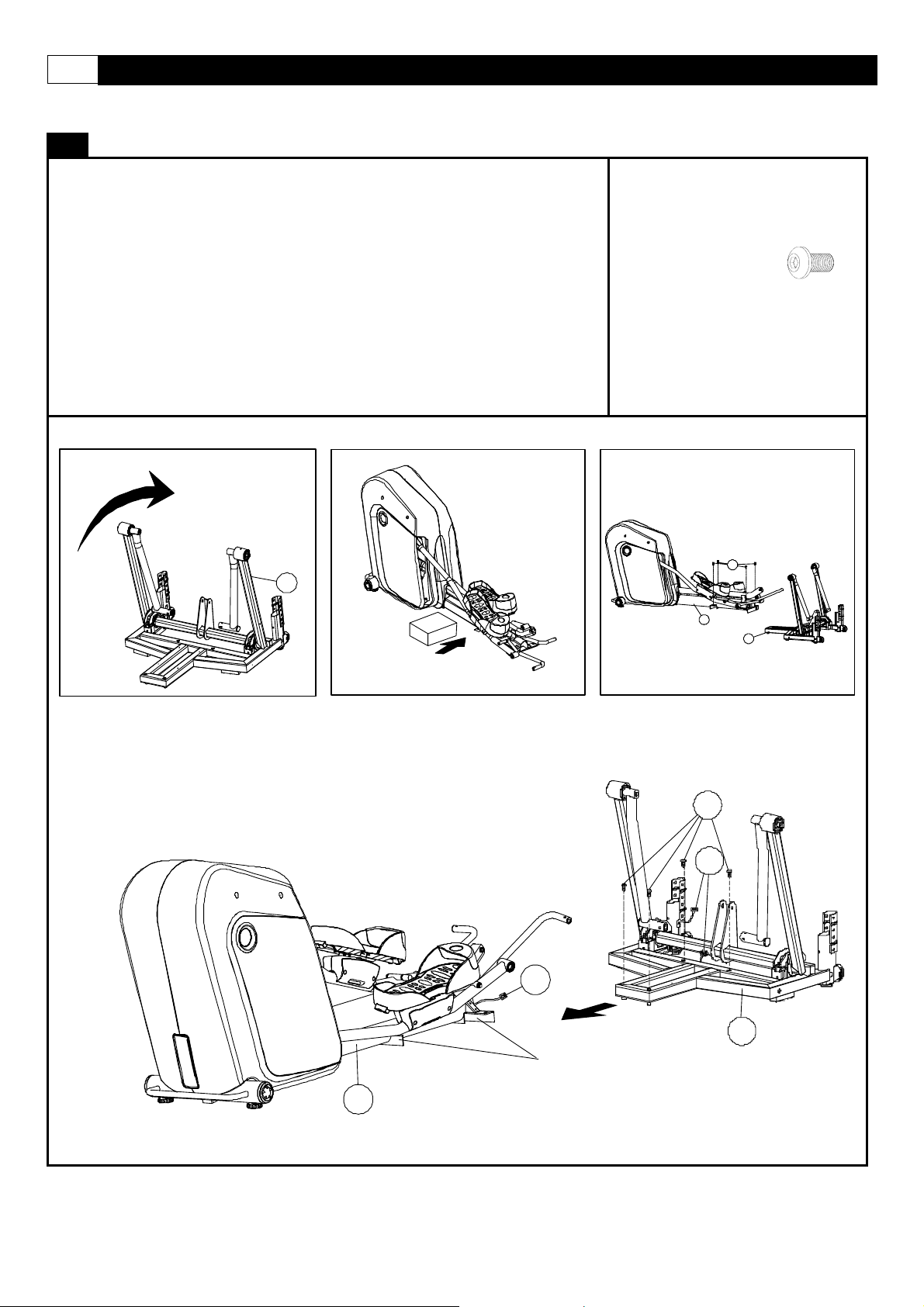
TRANSPORT INSTRUCTION
TRANSPORT INSTRUCTIONS:
To transport your
shown.
AGILE Dynamic Motion Trainer simply lift the back end and roll it away to the desired location, as
www.smoothfitness.co.uk
41
Page 42

42 SMOOTH AGILE TRAINER
MUSCLE CHART
Targeted muscle groups:
The exercise routine that is performed on this product will develop primarily lower body muscle groups. These muscle groups
are shown in gray color on the chart below.
MUSCLE GROUPS
A Shoulder muscles Calf muscles G
B Pectoral muscles Trapezius muscles H
C Bicep muscle Tricep muscles I
D Abdominal muscles Back muscles J
E Forearm muscles Gluteal muscles K
F Quadricep muscles Hamstring muscles L
Page 43

www.smoothfitness.co.uk
STRETCHING ROUTINE
Warm up and cool down:
A successful exercise program consists of a warm-up, aerobic exercise, and a cool-down. Do the entire program at least two and
preferably three times a week, resting for a day between workouts. After several months, you can increase your workouts to four
or five times per week.
Warming up is an important part of your workout, and should begin every session. It prepares your body for more strenuous
exercise by heating up and stretching out your muscles, increasing your circulation an d pulse rate, and delivering more oxygen to
your muscles. At the end of your workout, repeat these exercises to reduce sore muscle problems. We suggest the warm-up and
cool-down exercises on the following pages:
Toe Touch:
Slowly bend forward from
your waist, letting your back
and shoulders relax as you
stretch toward your toes.
Reach down as far as you
can and hold for 15 counts.
Shoulder Lift:
Lift your right shoulder up
toward your ear for one
count. Then lift your left
shoulder up for one count as
you lower your right shoulder.
43
Inner Thigh Stretch:
Sit with the soles of your feet
together with your knees
pointing outward. Pull your
feet as close into your groin
as possible. Gently push
your knees towards the floor.
Hold for 15 counts.
Side Stretch:
Open your arms to the side
and continue lifting them until
they are over your head.
Reach your right arm as far
upward toward the ceiling as
you can for one count. Feel
the stretch up your right side.
Repeat this action with your
left arm.
Hamstring Stretch:
Sit with your right leg
extended. Rest the sole of
your left foot against your
right inner thigh. Stretch
toward your toe as far as
possible. Hold for 15 counts.
Relax and then repeat with
left leg extended.
Calf-Achilles Stretch:
Lean against a wall with your
left leg in front of the right
and your arms forward. Keep
your right leg straight and the
left foot on the floor; then
bend the left leg and lean
forward by moving your hips
toward the wall. Hold, and
then repeat on the other side
for 15 counts.
Head Roll:
Rotate your head to the right
for one count, feeling the
stretch up the left side of your
neck. Next, rotate your head
back for one count, stretching
your chin to the ceiling and
letting your mouth open.
Rotate your head to the left
for one count, and finally,
drop your head to your chest
for one count.
Page 44

44 SMOOTH AGILE TRAINER
COMPUTER OPERATION
A
B
C
D
E
I
J
K
F
G
H
DTAT DISPLAY-1
INTENSITY LEVEL
INTENSITY PROFILE
PROGRAMS
EXPRESS MOTION
INTENSITY-DOWN
STOP / ENTER
MOTION-DOWN
A I
B J
C K
D L
E M
F N
G
H
DTAT DISPLAY-2
MOTION LEVEL
MOTION PROFILE
INTENSITY-UP
START
MOTION-UP
L
M
N
Page 45

www.smoothfitness.co.uk
45
COMPUTER OPERATION
DISPLAY FUNCTIONS:
There are 6 display areas to show all the necessary information prior to and during the workout.
INTENSITY LEVEL DISPLAY:
Displays intensity level from 1 to 20.
8 x 16 DOT MATRIX INTENSITY LEVEL PROFILE DISPLAY:
Displays all operating instructions prior to the workout and displays intensity level profiles d uring the workout.
8 x 8 DOT MATRIX MOTION LEVEL PROFILE DISPLAY:
Displays motion level profiles during the workout.
MOTION LEVEL DISPLAY:
Displays motion levels from 1 to 12.
DATA DISPLAY 1:
Prior to using a preset program, data display 1 displays and allows user to set age, workout time and target heart rate.
During the workout, data display 1 displays TIME, RPM or PULSE depending on which display mode is selected. Scan mode can
also be selected to view all available data.
DATA DISPLAY 2:
Prior to using a preset program, data display 2 displays and allows user to set weight, distance target, calorie target or watt target.
During the workout, data display 2 displays DISTANCE, CALORIES or WATTS depending on which display mode is selected.
Scan mode can also be selected to view all available data.
DISPLAY MODES:
Mode 1: Scan mode (scans through display modes 2-4)
Mode 2: TIME and DISTANCE
Mode 3: RPM and CALORIES
Mode 4: PULSE and WATTS
COMPUTER OPERATION:
POWER ON:
Plug in the POWER CORD and set the power switch to ON. All the LED windows will light up and begin scanning. The
INTENSITY LEVEL Dot Matrix displays and begins scrolling “SELECT-QUICK-START-OR-PROGRAM”. The other LED windows
will show the factory settings as follows:
INTENSITY LEVEL window display: “1”
MOTION LEVEL window display: “1”
DATA DISPLAY-1: displays (default AGE): ”35”, AGE LED light on.
DATA DISPLAY-2: displays (default WEIGHT): “150” lb, WEIGHT LED light on.
During the workout, press the STOP button twice to return to POWER ON status.
SLEEP MODE:
The computer will automatically enter SLEEP MODE if left idle for 3 minutes without any input in POWER ON status. When the
computer is in SLEEP MODE, press any button or pedal and the machine will return to POWER ON status. You can turn SLEEP
MODE off but the console will be drawing power indefinitely if it is plugged in to keep the LEDs lit. To turn SLEEP MODE off, get
the console to POWER ON status then press INTENSITY UP and DOWN buttons and hold for 5 seconds. Data display 2 will
show “1”. Press the START button and data display 2 will display the SLEEP MODE status. To toggle between “On” and “Off”,
select INTENSITY UP or DOWN then press STOP/ENTER to confirm and return to POWER ON status.
PAUSE/STOP:
During the workout, press the STOP button or stop pedaling for 10 seconds to enter PAUSE status. The INTENSITY LEVEL Dot
Matrix display will show “PAUSE”. All the figures on the console will be frozen. Press the START button or start pedaling to
resume the program and all the displays will
Page 46

46 SMOOTH AGILE TRAINER
COMPUTER OPERATION
continue the performance until the program finishes. If you leave the pedal stopped for over 3 minutes or press the ST OP button
twice, all the data will return to 0 and the computer will return to POWER ON status.
ENGLISH/METRIC CONVERSION:
The console display can show ENGLISH and METRIC information. The factory should have the proper setting on this for the
different markets. In case it needs to be converted between METRIC and ENGLISH readout, please follow the procedure below:
1.Set the POWER SWITCH to ON. Press both the STOP and MOTION UP button at the same time and hold for 3 seconds. The
INTENSITY LEVEL Dot Matrix will display and scrolling “KM” or “ML”. KM is displayed for METRIC and ML for ENGLISH.
2. Press the INTENSITY UP/DOWN button to switch between Metric and English then pressing STOP/ENT ER to save the setting
and return to Power On status.
SOUND on/off:
From the POWER ON status press and hold INTENSITY UP and DOWN buttons for 5 seconds to get to the display control mode.
The data display 2 will be displaying “1”. Press INTENSITY UP once so that “2” is displaying then press the START button. To
toggle between sound “on” or “off” use the INTENSITY UP or DOWN button then press STOP/ENTER to confirm and return to
POWER ON status.
PROGRAM OPERATING INSTRUCTION
QUICK START:
When the console is in POWER ON status, press the START button to activate the QUICK START program. The Intensity Level
Display shows “1” and the INTENSITY LEVEL Dot Matrix displays the intensity level profile. The Motion Level Display shows “1”
and the MOTION LEVEL Dot Matrix displays motion level profile. Press the INTENSITY UP/DOWN button to change the inte nsity
level. Press the MOTION UP/DOWN button to change the motion level. The TIME, CALORIES and DISTANCE will count up from
0.
TARGET PROGRAM:
When the console is in POWER ON status, press the TARGET program button once to enter the TARGET TIME program set up:
Press TARGET program button twice to enter the TARGET DISTANCE program set up,
Press TARGET PROGRAM button three times to enter the TARGET CALORIES program set up
Continue the rotation among these three target programs by pressing the TARGET program button.
Target Time:
Press the TARGET program button once to get to the TARGET TIME program, then press STOP/ENTER to enter the set up
procedure.
TIME display shows the factory default setting “30:00”. Press INTENSITY UP/DOWN button to adjust the target time and press
STOP/ENTER to confirm.
AGE display shows factory default setting “35” . Press INTENSITY UP/DOWN button to adjust the user age and press
STOP/ENTER to confirm.
WEIGHT display shows factory default setting “68(kgs)/150(Lb). Press INTENSITY UP/DOWN button to adjust the user weight
and press STOP/ENTER to confirm.
Press START button to start the target time program. Time counts down to 0, Distance and Calories count up. Press INTENSITY
UP/DOWN to adjust the resistance and press MOTION UP/DOWN to adjust the motion.
Target Distance:
Press the TARGET program button twice to get to the TARGET DISTANCE program then press STOP/ENTER to enter the set up
procedure.
DISTANCE display shows factory default setting “5.00”. Press INTENSITY UP/DOWN button to adjust the target distance and
press STOP/ENTER to confirm.
AGE display shows factory default setting “35”. Press INTENSITY UP/DOWN button to adjust the user age and press
STOP/ENTER to confirm.
Page 47

www.smoothfitness.co.uk
47
COMPUTER OPERATION
WEIGHT display shows factory default setting “68(kgs)/150(Lb). Press INTENSITY UP/DOWN button to adjust the user weight
and press STOP/ENTER to confirm.
Press START button to start the target distance program. Distance counts down to 0, Time and Calories count up. Press
INTENSITY UP/DOWN to adjust the resistance and press MOTION UP/DOWN to adjust the motion.
Target Calories:
Press the TARGET program button three times to get to the TARGET CALORIES program, then press STOP/ENTER to enter the
set up procedure.
CALORIES display shows factory default setting “50”. Press INTENSITY UP/DOWN button to adjust the target calories and press
STOPE/ENTER to confirm.
AGE display shows factory default setting “35”. Press INTENSITY UP/DOWN button to adjust the user age and press
STOP/ENTER to confirm.
WEIGHT display shows factory default setting “68(kgs)/150(Lb). Press INTENSITY UP/DOWN button to adjust the user weight
and press STOP/ENTER to confirm.
Press START button to start the target distance program. Calories counts down to 0, Time and Calories count up. Press
INTENSITY UP/DOWN to adjust the resistance and press MOTION UP/DOWN to adjust the motion.
FAT BURNING PROGRAM
When the console is in POWER ON status, press the FAT BURNING program button then press STOP/ENTER to continue the set
up procedure.
TIME display shows factory default setting “30:00”. Press INTENSITY UP/DOWN button to adjust the target time and press
STOP/ENTER to confirm.
AGE display shows factory default setting “35”. Press INTENSITY UP/DOWN button to adjust the user age and press
STOP/ENTER to confirm.
WEIGHT display shows factory default setting “68(kgs)/150(Lb). Press INTENSITY UP/DOWN button to adjust the user weight
and press STOP/ENTER to confirm.
Press START button to start the FAT BURNING program. Time counts down to 0, Distance and Calories count up. Dot Matrix
display shows the pre-set INTENSITY and MOTION profile. Press INTENSITY UP/DOW N to adjust the resistance and press
MOTION UP/DOWN to adjust the motion.
INTERVAL PROGRAM
When the console is in POWER ON status, press the INTERVAL program button once to select the INTENSITY INTERVAL
program then press STOP/ENTER to enter the program set up procedure.
OR
Press INTERVAL program button twice to select the MOTION INTERVAL program then press STOP/ENTER to enter the program
set up procedure.
Continue the rotation between these two INTERVAL programs by pressing the INTERVAL program bu tton.
Intensity Interval Program
When the console is in INTENSITY INTERVAL program set up, INTENSITY LEVEAL DISPLAY shows “L1”. This indicates the
intensity level for the intervals. Use the INTENSITY UP/DOWN buttons to change the intensity then press STOP/ENTER button to
enter to confirm.
TIME display shows factory default setting “32:00”. Press INTENSITY UP/DOWN button to adjust the target time and press
STOP/ENTER to confirm.
AGE display shows factory default setting “35”. Press INTENSITY UP/DOWN button to adjust the user age and press
STOP/ENTER to confirm.
WEIGHT display shows factory default setting “68(kgs)/150(Lb). Press INTENSITY UP/DOWN button to adjust the user weight
and press STOP/ENTER to confirm.
Page 48

48 SMOOTH AGILE TRAINER
COMPUTER OPERATION
Press START button to start the INTENSITY INTERVAL program. Time counts down to 0, Distance and Calories count up. Dot
Matrix display shows the pre-set INTENSITY and MOTION profile. Press INTENSIT Y UP/DOWN to adjust the resistance and
press MOTION UP/DOWN to adjust the motion.
Motion Interval Program
When the console is in MOTION INTERVAL program set up, MOTION LEVEAL DISPLAY shows “L1”. This indicates the intensity
level for the intervals. Use the INTENSITY UP/DOWN buttons to change the intensity then press STOP/ENTER button to confirm.
TIME display shows factory default setting “32:00”. Press INTENSITY UP/DOWN button to adjust the target time and press
STOP/ENTER to confirm.
AGE display shows factory default setting “35”. Press INTENSITY UP/DOWN button to adjust the user age and press
STOP/ENTER to confirm.
WEIGHT display shows factory default setting “68(kgs)/150(Lb). Press INTENSITY UP/DOWN button to adjust the user weight
and press STOP/ENTER to confirm.
Press START button to start the MOTION INTERVAL program. Time counts down to 0, Distance and Calories count up. Dot
Matrix display shows the pre-set INTENSITY and MOTION profile. Press INTENSIT Y UP/DOWN to adjust the resistance and
press MOTION UP/DOWN to adjust the motion.
ENDURANCE PROGRAM
When the console is in POWER ON status, press the ENDURANCE program button then press STOP/ENTER to continue to the
set up procedure.
Workout Level set up
TIME display shows “L1”, Press INTENSITY UP/DOWN button to adjust the workout level and press STOP/ENTER to confirm.
TIME display shows factory default setting “32:00”. Press INTENSITY UP/DOWN button to adjust the target time and press
STOP/ENTER to confirm.
AGE display shows factory default setting “35”. Press INTENSITY UP/DOWN button to adjust the user age and press
STOP/ENTER to confirm.
WEIGHT display shows factory default setting “68(kgs)/150(Lb). Press INTENSITY UP/DOWN button to adjust the user weight
and press STOP/ENTER to confirm.
Press START button to start the ENDURANCE program. Time counts down to 0, Distance and Calories count up. Dot Matrix
display shows the pre-set INTENSITY and MOTION profile. Press INTENSITY UP/DOW N to adjust the resistance and press
MOTION UP/DOWN to adjust the motion.
WATTS CONTROL PROGRAM
The function of Watts Control program is to allow the user to set a desired workout load (watts). The user’s workout
load is controlled automatically by increasing or decreasing the resistance as the user changes their stride cadence
(RPM). The intensity will be reduced when user increases RPM and the intensity will be increased when the user
decreases the RPM.
When the console is in POWER ON status, press the WATTS CONTROL program button then press STO P/ENTER
to continue the set up procedure.
WATTS display shows factory default setting “110”. Press INTENSITY UP/DOWN button to adjust the target Watts and press
STOP/ENTER to confirm.
TIME display shows factory default setting “32:00”. Press INTENSITY UP/DOWN button to adjust the target time and press
STOP/ENTER to confirm.
AGE display shows factory default setting “35”. Press INTENSITY UP/DOWN button to adjust the user age and press
STOP/ENTER to confirm.
Page 49

www.smoothfitness.co.uk
49
COMPUTER OPERATION
WEIGHT display shows factory default setting “68(kgs)/150(Lb). Press INTENSITY UP/DOWN button to adjust the user weight
and press STOP/ENTER to confirm.
Press START button to start the WATTS program. Time counts down to 0, Distance and Calories count up. Dot Matrix display
shows the pre-set INTENSITY and MOTION profile. Press INTENSITY UP/DOWN to adjust the resistance and press MOTION
UP/DOWN to adjust the motion
TARGET HEART RATE CONTROL PROGRAM :
The TARGET HEART RATE CONTROL program is designed to keep the user training at their chosen heart rate level to achieve
the proper workout result. A heart rate monitoring device must be used for this program. The equipment provides a standard
contact handgrip on the moving handle bar to sense the user heart beat during the workout. The user must hold the contact
handgrips on the moving handle bar constantly in order to monitor the user heart rate during the workout. A wireless chest belt
transmitter is highly recommended for this program.
IMPORTANT: The console software will calculate the user’s SAFE MAXIMUM HEART RATE based on the formula:
220pbm-AGE. User’s are encouraged to consult with a doctor or personal
Training consultant to more accurately estimate their SAFE MAXIMUM HEART RATE in order to workout safely.
When the console is in POWER ON status, press the HEART RATE CONTROL program button. The 8x16 Dot Matrix displays
“HEART RATE CONTROL” Press STOP/ENTER to continue to the set up procedure.
TIME display shows factory default setting “30:00”. Press INTENSITY UP/DOWN button to adjust the target time and press
STOP/ENTER to confirm.
AGE display shows factory default setting “35”. Press INTENSITY UP/DOWN button to adjust the user age and press
STOP/ENTER to confirm.
PULSE display shows the calculated TARGET HEART RATE based on the user age setting from the above step. The TARGET
HEART RATE = 85% MAXIMUM SAFE HEART RATE. Press INTENSITY UP/DOWN button to adjust the target heart rate then
press the STOP/ENTER bottom to confirm.
WEIGHT display shows factory default setting “68(kgs)/150(Lb). Press INTENSITY UP/DOWN button to adjust the user weight
and press STOP/ENTER to confirm.
Press the START button to start the 3 minute WARM UP. The purpose of warm up program is to bring the user’s heart rate to 65%
of the MAXIMUM SAFE HEART RATE. Time counts down from “3.00” to “0:00”. Intensity Level Profile displays “WARM UP” 3
times. During the WARM UP, if the actual heart rate is less than 65% of the user’s MAXIMUM SAFE HEART RATE, the intensity
level will be increased by 1 level every 15 seconds. If the actual heart rate reaches 65% MAXIMUM SAFE HEART RATE twice
within the warm up, the HEART RATE CONTROL program will start.
If user’s actual hear rate fails to reach 65% of MAXIMUM SAFE HEART RATE during the warm up, the user will be placed into a
nd
or 3rd (if necessary) 3 minute warm up program. If user’s actual heart rate fails to reach 65% of the MAXIMUM SAFE HEART
2
RATE after the 3
status in 10 seconds.
Once the user successfully enters the HEART RATE CONTROL program, the computer will actively adjust the resistance level to
keep the users at the TARGET HEART RATE. If the user is consistently below the TARGET HEART RATE, the INTENSITY
LEVEL will increase 1 level. If the user reaches and exceeds the TARGET HEART RATE, the INTENSITY LEVEL will decreas e 1
level. The program will continue until the time runs out. If the user’s heart rate continues to exceed the TARGET HEART RATE for
3 minutes, or the time counts down to “0:00”, the heart rate control program will stop and start the 1 minute COOL DOWN function.
Time counts down from “1:00” and INTENSITY LEVEL AND MOTION LEVEL at level 1.
rd
3 warm up program, the INTENSITY LEVEL PROFILE dot matrix will display “FAIL” then return to POWER ON
Page 50

50 SMOOTH AGILE TRAINER
WARRANTY
Read and follow the Assembly-instructions and the User’s-Manual before using this pro duct.
Warranty Coverage: Smooth Fitness GmbH ("Smooth Fitness") warrants to the original owner that each new product to be
free from defects in workmanship and material.
This warranty is limited on home use only.
Period of Coverage: The Home-Use-Warranty on this product runs from the date of original purchase using the following
schedule:
MODEL FRAME Electronics Parts Labor
AGILE DMT Lifetime 2 years 2 years 2 years
- Smooth Fitness will provide a replacement part free of charge if a defect is found during the Warranty period of 2
years.
- Smooth Fitness reserves the right to inspect damaged parts for misuse.
- For Corporate Use (Up to 3 hours use per day): The Warranty on this product runs from the date of your purchase for
a period of ONE (1) year.
It is required to show a proof of purchase prior to warranty service being initiated. Your Original Receipt is proof of purchase
and should be kept with the product manual.
As a matter of course we will be available and open for all your problems even when the warrant y has already expired. Simply
call the service number down below.
Any redemption may be by repair or replacement of the affected parts and/or product at the sole
discretion of Smooth Fitness, and it’s authorized Service Partners. If repairs are required, the unit will be
repaired at the location of use or by return to the factory as deemed appropriate by Smooth Fitness.
Parts repaired or replaced pursuant to this Warranty shall be warranted for the unexpired portion of the Warranty applying to
the original product. Any technical advice furnished before or after delivery in regard to the use or app lication of Smooth
Fitness products is furnished without charge and on the basis that it represents Smooth Fitness' best judgment under the
circumstances but that the advice is used at your sole risk.
Procedure for Obtaining Your Remedy Under This Warranty: To obtain service on a Smooth Fitness product, please call
the Smooth Fitness Service Partner under 0800-09 72 100. To help the technician assist you, please have the following
information ready:
• Model name or number from the cover of the manual;
• Serial number located on the frame of the unit; and
• The part description and the order number.
Limitations on Warranty: This Warranty does not cover wear and tear, any problems, damages or failures that are caused by
accident, improper assembly, failure to observe cautionary labels on the product, failure to operate the product correctly,
abuse or freight damage. Smooth Fitness does not warrant against any damage or defects that may result from repair or
alterations made to the product by an unauthorized repair facility.
This Warranty does not apply to any product shipped or handled outside of Germany, Austria and England. This Warranty
does not apply if the product is used as a rental product or in commercial use. Consequential and incidental damages are not
recoverable under this Warranty.
RESEPECTIVE LAWS OF THE COUNTRIES OF SALE REMAIN UNTOUCHED. THIS WARRANTY IS
EXPRESSLY IN LIEU OF ALL OTHER EXPRESS WARRANTIES. THE PERIOD OF COVERAGE OF THIS
WARRANTY RUNS FROM THE DATE OF PURCHASE: SMOOTH FITNESS IS NOT LIABLE FOR
CONSEQUENTIAL OR INCIDENTAL DAMAGES RESULTING FROM ANY DEFECT IN PARTS. SMOOTH
FITNESS' SOLE LIABILITY UNDER THIS WARRANTY IS LIMITED TO THE TERMS DESCRIBED IN THIS
FORM, AS LONG NOT GOVERNED DIFFERENTLY BY LOCAL LAW:
For assistance with assembly or to order replacement parts, please call the Smooth Fitness Service Partner under 0800-09 72
100. To help them assist you, please have the following information ready:
• Model name or number from the cover of the manual;
• Serial number located on the frame of the unit; and
• The part description and order number.
Page 51

www.smoothfitness.de
51
ACHTUNG: Um die Gefahr von Verbrennungen, Feuer, elektrischen Schläge n und sonstigen Verletzungen zu
reduzieren, lesen Sie bitte die folgenden wichtigen Sicherheitshinweise und Informationen, bevor Sie den Elliptical
Trainer benutzen. Es liegt in der Verantwortung des Eigentümers sicher zu stellen, dass alle Benutzer dieses Elliptical
Trainers hinreichend über alle Sicherheitshinweise und Gefahren informiert wurden.
SICHERHEITSHINWEISE
• Benutzen Sie den Elliptical Trainer nur wie es in dieser Anleitung beschrieben ist.
• Platzieren Sie den Elliptical Trainer nur auf ebenem Untergrund und mit genügend Freiraum dahinter.
Platzieren Sie den Elliptical Trainer niemals an Plätzen, die Luftöffnungen blockieren. Legen Sie eine Matte
unter den Elliptical Trainer, um den Boden oder Teppich vor eventueller Beschädigung zu schützen.
• Stellen Sie bei der Wahl eines Aufstellungsortes sicher, dass eine Steckdose in der Nähe ist.
• Benutzen Sie den Elliptical Trainer nur innen und schützen Sie ihn vor Feuchtigkeit und Staub. Stellen Sie den
Elliptical Trainer nicht in eine Garage, unter eine überdachte Veranda oder in die Nähe von Wasser.
• Benutzen Sie den Elliptical Trainer nicht an einem Ort an dem Sprühvorgänge vorgenommen werden oder mit
Sauerstoff umgegangen wird.
• Lassen Sie Kinder unter 12 Jahren und Haustiere zu keiner Zeit in die Nähe des Elliptical Trainers.
• Der Elliptical Trainer sollte nicht von Personen benutzt werden, die mehr als 160kg (350lbs) wiegen.
• Erlauben Sie nur jeweils einer Person die Benutzung des Elliptical Trainers. Tragen Sie angemessen e
Trainingskleidung wenn Sie den Elliptical Trainer benutzen. Tragen Sie während des Trainings keine weiten
Kleidungsstücke die sich im Elliptical Trainer verfangen könnten. Zweckmäßige Sportbeklei dung wird für
Männer und Frauen gleichsam empfohlen. Tragen Sie immer Sportschuhe. Benutzen Sie den Elliptical Trainer
niemals barfuss, nur in Strümpfen, oder in Sandalen.
• Wenn Sie das Netzkabel einstecken, achten Sie darauf, dass Sie einen geerdeten Stromkreis verwenden.
Kein anderes Gerät sollte über denselben Stromkreis laufen.
• Überprüfen Sie den Elliptical Trainer vor jeder Benutzung, um sicher zu stellen, dass alle Teile richtig
funktionieren.
• Führen Sie niemals Gegenstände oder Körperteile in die Öffnungen des Geräts ein.
• Folgen Sie den Empfehlungen der Sicherheitshinweise beim Einstecken Ihres Elliptical Trainers.
• Achten Sie darauf, dass das Netzkabel nicht in die Nähe der Pedale des Elliptical Trainer gerät und lassen Sie
das Netzkabel nicht unterhalb des Elliptical Trainer verlaufen. Benutzen Sie den Elliptical Trainer nie mit einem
beschädigten oder ausgefransten Netzkabel.
• Entfernen Sie den Elliptical Trainer jedes Mal vom Stromnetz bevor Sie ihn säubern oder warten. Wartungen
und Reparaturen am Elliptical Trainer sollten nur von einem, vom Hersteller autorisierten, Servicepartner
vorgenommen werden. Ein Nicht-Befolgen dieser Anweisung hat den Verfall der Garantie des Elliptical T raine r
zur Folge.
Page 52

52 SMOOTH AGILE TRAINER
FEHLENDE ODER FEHLERHAFTE ERDUNG IHRES GERÄTS ERHÖHT DAS RISIKO EINES ELEKTROSCHOCKS.
FALLS SIE ZWEIFEL HABEN, ZIEHEN SIE BITTE EINEN QUALIFIZIERTEN ELEKTRIKER HINZU UND LASSEN
ÜBERPRÜFEN OB DAS GERÄT SACHGEMÄSS GEERDET IST. NEHMEN SIE KEINE EINGRIFFE AN DEN
MITGELIEFERTEN NETZKABELN VOR. SOLLTEN DIE MITGELIEFERTEN NETZKABEL NICHT PASSEN
KONTAKTIEREN SIE BITTE EINEN QUALIFIZIERTEN ELEKTRIKER ODER EIN ELEKTROFACHGESCHÄFT.
Dieser Elliptical Trainer kann durch plötzliche Spannungsschwankungen beschä digt werden.
Spannungsschwankungen können durch Unwetter oder das Ein – und Ausschalten anderer Elektrogeräte im selben
Haushalt entstehen. Verwenden Sie immer einen Spannungsschutz um die Gefahr der Beschädigung zu verringern.
Entsprechende Spannungsschützer können im Fachhandel erworben werden.
Dieser Elliptical Trainer wird mit 2 Netzkabeln für Zentraleuropa und United Kingdom geliefert. Diese Netzkabel
verfügen über einen Erdungspol. Bitte wählen Sie das passende Netzkabel und schließen das Gerät an.
Bevor Sie das Gerät anschließen, vergewissern Sie sich, dass die lokale Spannung mit den Anforderungen des
Gerätes übereinstimmen.
Dieses Gerät ist für eine Spannung von 230V +
Verwenden Sie das Gerät nicht mit einem Spannungswandler.
Verwenden Sie das Gerät nicht mit einem Verlängerungskabel, wenn Sie nicht sicher sind ob die Erdung g ewä hrleistet
ist.
Abbildung zu den unterschiedlichen Ansteckmöglichkeiten:
STROMVERSORGUNG
5% ausgelegt.
Page 53

www.smoothfitness.de
53
Öffnen Sie die Kartonagen:
Nun können Sie die Kartonagen mit dem neuen Equipment öffnen. Verschaffen Sie sich einen Überblick über alle
Teile die Sie in den Kartonagen finden. Vergleichen Sie diese mit der Einzelteil-Übersichtslist e um sicherzustellen,
dass alle Teile in richtiger Anzahl vorhanden sind. Falls Sie ein Teil vermissen sollten, oder Fragen zu m Aufbau
haben, setzen Sie sich bitte mit dem Hersteller in Verbindung.
Legen Sie Werkzeug bereit:
Bevor Sie mit dem Aufbau Ihres Gerätes beginnen, sollten Sie überprüfen, ob Sie alle Werkzeuge, die Sie zum Aufbau
benötigen, bereitgelegt haben. Mit der richtigen Vorbereitung und dem richtigen Werkzeug zur Hand, sollte der Aufbau
schneller und müheloser von statten gehen.
Räumen Sie sich eine Arbeitsfläche frei:
Stellen Sie sicher, dass Sie genügend Fläche frei geräumt haben, um den Aufbau korrekt durch zufü hren. Entfernen
Sie alle Gegenstände an denen man sich beim Aufbau verletzen könnte. Achten Sie darauf, dass nach dem Aufbau
eine ausreichend große Fläche für den ungestörten Betrieb des Gerätes zur Verfügung steht.
Lassen Sie sich von einem Freund helfen:
Manche der Aufbauschritte verlangen schweres Heben. Es wird empfohlen, dass Sie sich beim Aufbau dieses
Produkts von einer anderen Person unterstützen lassen.
Maximales Benutzergewicht:
Bitte beachten Sie, dass für dieses Produkt eine Gewichtsbeschränkung vorliegt. Falls Sie mehr als 160 kg (350lbs)
wiegen sollten, ist die Verwendung dieses Produktes nicht empfehlenswert. Es können ernsthafte
Verletzungen auftreten, wenn das Benutzergewicht die hier angegebene Grenze überschreitet. Dieses Produkt
ist nicht für Menschen ausgelegt, deren Gewicht diese Grenze überschreitet.
VORBEREITUNG
Page 54

54 SMOOTH AGILE TRAINER
r
Zu Ihrer Unterstützung haben wir hier alle Bauteile aufgeführt, die zum Aufbau dieses Produkts benötigt we rden.
KARTON - A
LIEFERUMFANG
Main Frame Assembly
Hauptrahmen Griffstütze
KARTON - B
Fixed Handlebar
Haltegriff
Ständer links Ständer-Rechts Abdeckkappen
Upright-Left
[ 110 ]
Base Frame
Grundrahmen
Upright -Right
[ 111 ]
Undercarriage Cover
Untere Abdeckungen Haltebügel
Pivot Arm Cover
Handleba
[ 719 / 720 ]
Assembly
Console Support
Page 55

www.smoothfitness.de
Zu Ihrer Unterstützung haben wir hier alle Bauteile aufgeführt, die zum Aufbau dieses Produkts benötigt we rden.
LIEFERUMFANG
KARTON - C
55
Verkleidungen LL-LR
Front Side Panel
[ 709 / 710 ]
KARTON - D
Verkleidungen RL-RR
[ 712 / 711 ]
Computer
Computer
Page 56

56 SMOOTH AGILE TRAINER
Zu Ihrer Unterstützung haben wir hier alle Einzelteile und Werkzeuge aufgeführt, die zum Aufbau dieses Produkts
benötigt werden. Diese Übersicht soll Ihnen dabei helfen, Einzelteile zu identifizieren, die Sie nicht zuordnen können.
Der Maßstab unten soll beim messen und vergleichen von Teilen behilflich sein.
LIEFERUMFANG, EINZELTEILE UND WERKZEUGE
KARTON - E
701 Abdeckung, seitlich oben-links
702 Abdeckung, seitlich oben-rechts
703 Hintere Computerabdeckung
326 Gehausezapfen
4Stuck
717 Abdeckkappe
718 Abdeckkappe
721 Abdeckung
2Stuck
2Stuck
2Stuck
501
502
503
504
505
506
507
508
509
Schraubendreher-L
(1 Stuck)
J
Stromkabel
12x62-M10x20mmSchraube
20x78-M14x35mmSchraube
M5 x 8mm Schraube
M8 x 20mm Schraube
M8 x 40mm Schraube
M8 x 65mm Schraube
M10 x 20mm Schraube
M10 x 62mm Schraube
M6 x 40mm Schraube
2.5mm
lmbus
(1Stuck)
5mm
lmbus
(1Stuck)
K
Brustgurt
6mm
lmbus
(1Stuck)
2Stuck
2Stuck
2Stuck
4Stuck
2Stuck
2Stuck
4Stuck
1Stuck
2Stuck
8mm
lmbus
(1Stuck) Stuck)
510
511
512
513
514
515
516
517
518
519
14*17
Schlussel
(1
12 x 20 x 2 Unterlegscheibe
M10 selbsts. Mutter
4 x 12mm Schraube
4 x 19mm Schraube
12 x 18 x 24.5mm Einsatz
12 x 22 x 2 Unterlegscheibe
M5 x 6mm Schraube
selbsts. Mutter
M8
8x20x1.5mm
M8x105x20
Unterlegscheibe
Schraube
HGABCDEF
Schraubendreher
(1Stuck)
5mm
lmbus
(1Stuck)
2Stuck
1Stuck
1Stuck
6Stuck
2Stuck
2Stuck
2Stuck
Stuck
4
Stuck
4
Stuck
4
I
Trinkflasche
(
1Stuck)
Stuck)
(1Stuck)
MILLIMETER
(1 Stuck)
Page 57

www.smoothfitness.de
57
ERSATZTEILLISTE
Item No. Description Qty. Part No.
100
101 Haltegriff 1 AGILE-101
102 Querträger 1 AGILE-102
103 Haltebügel 1 AGILE-103
104 Grundrahmen 1 AGILE-104
105 Hauptrahmen 1 AGILE-105
106 Fußstütze links 1 AGILE-106
107 Fußstütze rechts 1 AGILE-107
108 Bewegl. Handgriffstange - links 1 AGILE-108
109 Bewegl. Handgriffstange - rechts 1 AGILE-109
110 Ständer - links 1 AGILE-110
111 Ständer - rechts 1 AGILE-111
112 Bügel zur Fußstütze - links 1 AGILE-112
113 Bügel zur Fußstütze - rechts 1 AGILE-113
114 Rahmen zur Höhenverstellung 1 AGILE-114
115 Rohr zur Höhenverstellung - vorderes 1 AGILE-115
116 Rohr zur Höhenverstellung - hinteres 1 AGILE-116
117 Schelle 2 AGILE-117
118 Schwungrad 1 AGILE-118
119 Aufhängung 1 AGILE-119
120 Schwing-Arm für Fußstütze 2 AGILE-120
121 Halterung, vordere 1 AGILE-121
122 Halterung, hintere 1 AGILE-122
200
201 Lager 6004 4 AGILE-201
202 Lager 6005 2 AGILE-202
203 Lager 6300 6 AGILE-203
204 Lager 6804 4 AGILE-204
205 Lager 2203 2 AGILE-205
206 Lager 6205 4 AGILE-206
207 Lager 608zz 8 AGILE-207
208 Kunststofflager 2"x38-20 2 AGILE-208
209 Kunststofflager 2"x38-9 2 AGILE-209
210 Elektromagnetisches System 1 AGILE-210
211 Lager, gefettet 2 AGILE-211
212 Abdeckung - obere 2 AGILE-212
213 Abdeckung - untere 2 AGILE-213
Page 58

58 SMOOTH AGILE TRAINER
ERSATZTEILLISTE
Nr. Beschreibung Anz. Best. NR
214 Riemen 1 AGILE-214
215 Aluminium-Scheibe 1 AGILE-215
216 Kurbel 25x186.7 1 AGILE-216
217 Kurbel 25x186.7 1 AGILE-217
218 Achse 1 AGILE-218
219 Rad 2 AGILE-219
220 Dämpfungsset Fußraster 2 AGILE-220
221 Höhenausgleichsrad 2 AGILE-221
222 Riemenscheibe 1 AGILE-222
224 Endkappe Haltegriff 2 AGILE-224
225 Handpulssensor 2 AGILE-225
226 Abdeckung, oval 2 AGILE-226
227 Handpulssensorabdeckung, hintere 2 AGILE-227
228 Schaumstoffüberzug 2 AGILE-228
229 Fixierung EMS 1 AGILE-229
230 Schwungradfixierung 1 AGILE-230
231 Sensorfixierung 1 AGILE-231
232 Platte für Dämpfungsset Fußraster 2 AGILE-232
233 Fixierung Dämpfungsset Fußraster 2 AGILE-233
234 Abdeckung, oval 1 AGILE-234
235 Ein-/Ausschaltrahmen 1 AGILE-235
238 Lager 2201 2 AGILE-238
239 5/16" Kabelbinder 1 AGILE-239
240 1/8" Kabelbinder 1 AGILE-240
241 3/8" Kabelbinder 4 AGILE-241
242 Lager für Rad 4 AGILE-242
243 Lager 6000 3 AGILE-243
244 Clip 1 AGILE-244
249 3/16" Kabelbinder 1 AGILE-249
250 1/4" Kabelbinder 9 AGILE-250
251 Ring für Handgriff 2 AGILE-251
252 Unterstützung für Lager 1 AGILE-252
253 Distanzhülse 1 AGILE-253
300
302 Hintere Abdeckung - links 1 AGILE-302
303 Hintere Abdeckung - rechts 1 AGILE-303
304 Einsatz hintere Abdeckung - links 1 AGILE-304
305 Einsatz hintere Abdeckung - rechts 1 AGILE-305
Page 59

www.smoothfitness.de
59
ERSATZTEILLISTE
Nr. Beschreibung Anz. Best. NR
306 Einsatz für Ein-/Ausschalter 1 AGILE-306
307 Pedal 2 AGILE-307
308 Vorderer Einsatz Pedal 2 AGILE-308
309 Dämpfungseinlage Pedal 2 AGILE-309
310 Pedalabdeckung - links 2 AGILE-310
311 Pedalabdeckung - rechts 2 AGILE-311
312 Computergehäuse - oberes 1 AGILE-312
313 Computergehäuse - untere 1 AGILE-313
314 Obere Computerabdeckung 1 AGILE-314
315 Gummi-Streifen - 4 4 AGILE-315
316 Gummi-Streifen - 3 4 AGILE-316
317 Gummi-Streifen - 2 4 AGILE-317
318 Abdeckung - 1 2 AGILE-318
319 Abdeckung - 2 2 AGILE-319
320 Gummi-Streifen - 1 4 AGILE-320
321 Einsatz 2 AGILE-321
322 Rohrfixierung 1 AGILE-322
323 Kunststoffeinsatz für Bef. Neigungsverstellung 4 AGILE-323
324 Abdeckung für Controller 1 AGILE-324
325 Abdeckkappe 2 AGILE-325
326 Gehäusezapfen 35 AGILE-326
327 Aufsatz 1 AGILE-327
328 Dämpfer 2 AGILE-328
329 Dämpfer 2 AGILE-329
330 Gummieinsatz – Vorne 2 AGILE-330
331 Gummieinsatz – Hinten 2 AGILE-331
332 Gehäusezapfen zur Fixierung 22 AGILE-332
333 Gehäusezapfen zur Fixierung 7 AGILE-333
336 Abdeckung, vordere 4 AGILE-336
337 Abdeckung, hintere 2 AGILE-337
338 Abdeckung Haltebügel - links 2 AGILE-338
339 Abdeckung Haltebügel - rechts 2 AGILE-339
340 Taste 1 AGILE-340
341 Gehäusezapfen zur Fixierung 3 AGILE-341
Page 60

60 SMOOTH AGILE TRAINER
ERSATZTEILLISTE
Nr. Beschreibung Anz. Best. NR
400
402 25 x 10 x 55 - M10 x 15mm Schraube 2 AGILE-402
403 M5 x 8mm Schraube 7 AGILE-403
404 M6 x 12mm Schraube 11 AGILE-404
405 M8 x 15mm Schraube 23 AGILE-405
406 M8 x 25mm Schraube 2 AGILE-406
407 M10 x 20mm Schraube 4 AGILE-407
408 M10 x 40mm Schraube 1 AGILE-408
409 M4 X 40mm Schraube 1 AGILE-409
410 M8 x 50mm Schraube 2 AGILE-410
411 M10 x 40mm Schraube 2 AGILE-411
412 M12 x 70mm Schraube 2 AGILE-412
414 M8 x 20mm Schraube 6 AGILE-414
415 M3 x 8mm Schraube 2 AGILE-415
416 M8 x 65mm Schraube 2 AGILE-416
417 M6 x 12mm Schraube 2 AGILE-417
418 M8 x 16mm Schraube 4 AGILE-418
419 M8 x 90mm Schraube 4 AGILE-419
421 M8 selbsts. Mutter 8 AGILE-421
422 M10 selbsts. Mutter 3 AGILE-422
423 M14 selbsts. Mutter 3 AGILE-423
424 M8 Mutter 2 AGILE-424
425 M6 x 15mm Schraube 2 AGILE-425
426 3/4" x 16 Mutter 2 AGILE-426
427 Achse für Schwungrad 1 AGILE-427
428 10 x 36mm Achse 2 AGILE-428
429 12 x 210 - M14 x 70mm Achse 1 AGILE-429
430 Distanzhülse 12 x 60 4 AGILE-430
431 M4 x 15mm Schraube 2 AGILE-431
432 4 x 12mm Schraube 8 AGILE-432
433 Achse für Handgriffe 1 AGILE-433
434 Achse 2 AGILE-434
Page 61

www.smoothfitness.de
61
ERSATZTEILLISTE
Nr. Beschreibung Anz. Best. NR.
435 Distanzhülse
436 M10 Sprengring
437 M12 Sprengring
438 M42 Sprengring
439 10 x 18 x T1.0 Unterlegscheibe
440 15 x 8 x T2.0 Unterlegscheibe
441 10 x 16 x T2.0 Unterlegscheibe
442 20 x 6 x T2.0 Unterlegscheibe
443 32 x 6 x T2.0 Unterlegscheibe
444 35 x 14 x T2.0 Unterlegscheibe
445 10 x 18 x T5.1 Unterlegscheibe
446 M3 x 16mm Schraube
447 M3 x 10mm Schraube
448 4 x 12mm Schraube
449 M2 x 6mm Schraub
450 4 x 12mm Schraube
451 M32 C Sprengring
452 M4 x 45mm Schraube
453 M4 x 8mm Schraube
454 7 x 12 - M5 x 5mm Mutter
456 10 x 23 x T2.0 Unterlegscheibe
457 6 x 10 x 1 Sprengring
458 28.6 x 35.5 Kunststofflager
459 12 x 20 x 0.5 Unterlegscheibe
460 12 x 20 x 2 PU Unterlegscheibe
461 4 x 12mm Blechschraube 6 AGILE-461
462 M8 x 16mm Schraube 8 AGILE-462
463 4 x 12mm Konusschraube 4 AGILE-463
464 4 x 30mm Schraube 2 AGILE-464
465 M4 Mutter 2 AGILE-465
500
501 12 x 62 - M10 x 20mm Schraube
502 20 x 78 - M14 x 35mm Schraube
503 M5 x 8mm Schraube
504 M8 x 20mm Schraube
505 M8 x 40mm Schraube
506 M8 x 65mm Schraube
507 M10 x 20mm Schraube
508 M10 x 62mm Schraube
509 M6 x 40mm Schraube 2 AGILE-509
2 AGILE-435
6 AGILE-436
2 AGILE-437
2 AGILE-438
2 AGILE-439
11 AGILE-440
7 AGILE-441
3 AGILE-442
1 AGILE-443
2 AGILE-444
4 AGILE-445
2 AGILE-446
18 AGILE-447
47 AGILE-448
8 AGILE-449
23 AGILE-450
2 AGILE-451
2 AGILE-452
4 AGILE-453
4 AGILE-454
4 AGILE-456
2 AGILE-457
2 AGILE-458
2 AGILE-459
2 AGILE-460
2 AGILE-501
2 AGILE-502
2 AGILE-503
8 AGILE-504
2 AGILE-505
2 AGILE-506
4 AGILE-507
1 AGILE-508
Page 62

62 SMOOTH AGILE TRAINER
ERSATZTEILLISTE
Nr. Beschreibung Anz. Best. NR.
510 12 x 20 x 2 Unterlegscheibe 2 AGILE-510
511 M10 selbsts. Mutter 1 AGILE-511
512 4 x 12mm Schraube 10 AGILE-512
513 4 x 19mm Schraube 6 AGILE-513
514 12 x 18 x 24.5mm Einsatz 2 AGILE-514
515 12 x 22 x 2 Unterlegscheibe 2 AGILE-515
516 M5 x 6mm Schraube 2 AGILE-516
517 M8 selbsts. Mutter 4 AGILE-517
518 8 x 20 x 1.5mm Unterlegscheibe 4 AGILE-518
519 M8 x 105 x 20mm Schraube 4 AGILE-519
600
601 Geschwindigkeitssensor 1 AGILE-601
602 Magnet 1 AGILE-602
603 Ein-/Ausschalter 1 AGILE-603
604 Sicherung 1 AGILE-604
605 Stromanschluss 1 AGILE-605
606 Empfänger 1 AGILE-606
607 Transformator 1 AGILE-607
608 Computerplatine 1 AGILE-608
609 Motor zur Neigungsverstellung 1 AGILE-609
610 Controller 1 AGILE-610
611 Aufkleber 1 AGILE-611
612 Computeraufkleber 1 AGILE-612
613 Elektromagnetisches Kabel 1 AGILE-613
614 Verbindungskabel zu Ein-/Ausschalter etc. 3 AGILE-614
615 8Pin Computerkabel, - oberes 1 - 200mm 1 AGILE-615
616 8Pin Computerkabel, - oberes 2 - 1000mm 1 AGILE-616
617 8Pin Computerkabel, - mittleres - 900mm 1 AGILE-617
618 8Pin Computerkabel, - unteres 1 - 800mm 1 AGILE-618
619 8Pin Computerkabel, - unteres 2 - 2700mm 1 AGILE-619
620 3C Stromkabel 1000mm 1 AGILE-620
621 Handpulskabel, oberes 350mm 2 AGILE-621
622 Handpulskabel, mittleres 620mm 2 AGILE-622
623 Handpulskabel, unteres 650mm 2 AGILE-623
624 Empfängerkabel 350mm 1 AGILE-624
626 Controller Verbindungskabel 250mm 1 AGILE-626
Page 63

www.smoothfitness.de
63
ERSATZTEILLISTE
Nr. Beschreibung Anz. Best. NR.
700
701 Abdeckung, seitlich oben - links 1 AGILE-701
702 Abdeckung, seitlich oben - rechts 1 AGILE-702
703 Hintere Computerabdeckung 1 AGILE-703
704 Verkleidung innen -LL 1 AGILE-704
705 Verkleidung innen -LR 1 AGILE-705
706 Verkleidung innen -RR 1 AGILE-706
707 Verkleidung innen -RL 1 AGILE-707
708 Einsatz 2 AGILE-708
709 Verkleidung außen -LL 1 AGILE-709
710 Verkleidung außen -LR 1 AGILE-710
711 Verkleidung außen -RR 1 AGILE-711
712 Verkleidung außen -RL 1 AGILE-712
713 Einsatz-LL 1 AGILE-713
714 Einsatz-LR 1 AGILE-714
715 Einsatz-RR 1 AGILE-715
716 Einsatz-RL 1 AGILE-716
717 Abdeckkappe 2 AGILE-717
718 Abdeckkappe 2 AGILE-718
719 Untere Abdeckung - links 1 AGILE-719
720 Untere Abdeckung - recht s 1 AGILE-720
721 Abdeckung 4 AGILE-721
A Schraubendreher-L 1 AGILE-A
B 2.5mm Imbus 1 AGILE-B
C 5mm Imbus 1 AGILE-C
D 6mm Imbus 1 AGILE-D
E 8mm Imbus 1 AGILE-E
F 14 x 17 Schlüssel 1 AGILE-F
G Schraubendreher 1 AGILE-G
H 5mm Imbus 1 AGILE-H
I Trinkflasche 1 AGILE-I
J Stromkabel 1 AGILE-J
K Brustgurt 1 AGILE-K
Page 64

64 SMOOTH AGILE TRAINER
EXPLOSIONSZEICHNUNG
Ein Großteil der hier abgebildeten Teile ist vom Werk aus vormontiert..
224
703
612
447
314
608
312
611
340
450
449
313
450
228
208
102
433
101
326
509
424
321
504
321
208
Page 65

EXPLOSIONSZEICHNUNG
Ein Großteil der hier abgebildeten Teile ist vom Werk aus vormontiert..
www.smoothfitness.de
65
709
512
513
332
332
332
701
326
326
517
506
416
519
713
447
110
315
316
317
320
447
227
714
209
504
721
326
448
518
336
501
519
518
517
510
337
515
251
432
451
513
238
505
225
338
447
336
432
339
338
201
448
108
514
112
513
513710
513
712
448
332
332
339
337
103
113
447
225
514
326
336
316
317
315
251
201
238
320
432
448
109
326
336
451
519
209
504
416
501
515
227
721
510
447
519
506
702
111
517
518
519
518
326
332
716
447
715
513
711
512
Page 66

66 SMOOTH AGILE TRAINER
EXPLOSIONSZEICHNUNG
Ein Großteil der hier abgebildeten Teile ist vom Werk aus vormontiert..
308
309
421
430
405
405
404
450
220
207
311
330
204
323
419
502
721
460
448
417
457
442
448
438
421
310
207
205
414
437
406
307
331
232
233
323
459
326
106
310
448
326
721
107
414
421
502
205
307
307
331
233
406
405
460
438
308
309
430
442
457
207
405
417
204
323
404
450
450
421
220
419
330
232
311
459
437
448
Page 67

EXPLOSIONSZEICHNUNG
Ein Großteil der hier abgebildeten Teile ist vom Werk aus vormontiert..
421
429
423
404
412
442
439
427
405
440
215
118
243
404
436
243
405
440
405
440
234
441
435
202
222
405
440
411
434
217
426
465
602
230
214
226
414
431
210
410
439
436
403
122
464
221
218
253
202
229
412
322
418
116-1
116-2
116-3
116-1
327
425
422
441
609
408
221
226
426
216
434
404
411
443
441
435
456
117
212
245
246
67
206
444
423
407
441
248
247
213
www.smoothfitness.de
423
444
717
503
718
503
717
206
458
206
407
441
456
117
212
248
247
213
116
440
440
418
245
246
211
120
516
325
511
114
115
325
508
206
458
Page 68

68 SMOOTH AGILE TRAINER
EXPLOSIONSZEICHNUNG
Ein Großteil der hier abgebildeten Teile ist vom Werk aus vormontiert..
704
450
708
705
319
304
332
318
448
302
448
463
463
252
402
333
445
415
203
333
445
403
448
601
333
446
105
403
235
422
403
231
603
605
119
604
409
306
512
121
463
249
448
250
324
219
720
436
448
512
452
428
448
242
461
436
328
461
329
104
219
436
512
428
436
242
707
450
708
326
450
326
706
512
326
450
719
512
240448
507
326
607
241
250
241
241
448
332
448
448
454
239
328
610
319
512
326
329
461
461
244
453
318
448
303
305
Page 69

EXPLOSIONSZEICHNUNG
Ein Großteil der hier abgebildeten Teile ist vom Werk aus vormontiert..
615
www.smoothfitness.de
69
621
624
606
340
620
607 609
613
619
601
626
613
617
623
615
623
616
623
622
617
618
620
619
613
619
614
620
614
620
Page 70

70 SMOOTH AGILE TRAINER
AUFBAU
( SCHRITT 1: Verbinden von Hauptrahmen und Grundrahmen
(A) Drehen Sie den Rahmen zur Höhenverstellung (114) senkrecht.
(B) Schieben Sie einen Karton unter den Hauptrahmen um Freiraum für das
montieren des Grundrahmens (104) zu schaffen.
(C) Positionieren Sie den Grundrahmen (104) unter den Bügel des
Hauptrahmens (105) und justieren Sie die 4 Schraublöcher.
(D) Entfernen Sie den Karton und senken Sie den Hauptrahmen (105) auf den
Grundrahmen (104). Der Bügel sollte fest auf dem Grundrahmen (104)
aufliegen. Befestigen Sie alles mit vier M10 x 20mm Schrauben (507).
114
507 X4
507
105
104
A
B
105
619
Bügel
Mounting Brackets
c
507
618
104
Page 71

AUFBAU
www.smoothfitness.de
71
SCHRITT 2 Montieren des Rohrs der Höhenverstellung
(A) Entfernen Sie die Rohrfixierung (322) und entsorgen Sie diese.
(B) Drehen Sie den Rahmen der Höhenverstellung (114) um die
Schraublöcher mit denen am Rohr zur Höhenverstellung, vorderes (115)
abzugleichen.
(C) Montieren Sie das Rohr zur Höhenverstellung, vorderes (115) am
Grundrahmen (104) mit einer M10 x 62mm Schraube (508) und einer M10
Mutter selbst sichernd (511) verwenden Sie den 6mm Imbus (D) und
Schlüssel (F).
(D) Verbinden Sie das 8Pin Computerkabel, (618) mit dem 8Pin
Computerkabel, unteres (619), und fixieren Sie diese mit dem Clip (244).
508 X1
511 X1
115
105
114
Abb. 2
D
508
F
511
104
619
FIG 2
618
244
Page 72

72 SMOOTH AGILE TRAINER
AUFBAU
SCHRITT 3 : Montieren der unteren Abdeckung
BEACHTEN:DIE UNTERE ABDECKUNG-LINKS (719) PASST ÜBER DAS
8PIN COMPUTERKABEL;UNTERES (618). VORSICHT BITTE DIE KABEL
BEIM MONTIEREN DER UNTEREN ABDECKUNG LINKS (719) NICHT
TRENNEN
(A) Heben Sie die Fußstütze und montieren Sie die untere Abdeckung, links (719)
am Grundrahmen (104), befestigen Sie diese mit vier 4 x 12 Schrauben (512).
(B) Wiederholen Sie den Vorgang auf der rechten Seite.
512 X4
512
720
104
107
106
618
105
512
719
Page 73

STEP 4: Assemble the Upright
A) Montieren Sie den Ständer links (110) und Ständer, rechts (111) am
Querträger und befestigen Sie diese mit zwei M8 x 56mm Schrauben (506).
Ziehen Sie die M8 x 56mm Schrauben bis zum Schritt C nicht komplett
fest.
(B) Stecken Sie den Ständer auf den Grundrahmen (104) und befestigen
Sie diesen mit vier M8 x 105 x 20mm Schrauben (519), vier M8 x 20 x
1.5mm Unterlegscheiben (518) und vier M 8 selbsts. Muttern (517).
(C) Ziehen Sie die M8 x 56mm Schrauben (506) fest
(D) Verbinden Sie das 8Pin Computerkabel unteres(618) mit dem 8 pin
Computerkabel mittleres (617). (
www.smoothfitness.de
506 X2
517 X4
518 X4
519 X4
73
506
111
109
102
108
110
506
517
519
111
518
617
518
517
519
519
110
519
517
518
104
618
Page 74

74 SMOOTH AGILE TRAINER
SCHRITT 5: Montieren der Verkleidung der beweglichen Handgriffe
(A) Schieben Sie das freie Ende des Schwing-Arms der Fußstütze (120)
durch das Loch in der Verkleidung, innen RL (707) und bringen diesen in die
endgültige Position. Siehe Abb. in SCHRITT1, SCHRITT 2 und SCHRITT 3.
(B) Montieren Sie die Verkleidung innen-RR (706) und die Verkleidung innen
RL (707) durch die Presspassung und befestigen Sie diese am Rahmen mit
zwei 4 x 12mm Schrauben (512).
(C) Wiederholen Sie den Vorgang auf der Linken Seite.
AUFBAU
SCHRITT 1
STEP1
707
120
512 X4
SCHRITT 2
STEP2
707
120
SCHRITT 3
STEP3
707
120
706
512
707
120
705
512
114
704
512
Page 75

SCHRITT 6:Montieren der Abdeckkappe
BEACHTEN: GLEICHEN SIE DIE 3 SCHNAPPVERSCHLÜSSE DER
ABDECKKAPPE (718) MIT DENEN DER ABDECKKAPPE (717).
(A) Montieren Sie die Abdeckkappe (717) am Swing Arm für die Fußstütze
(120) und befestigen Sie diese mit der M5 x 8mm Schraube (503).
(B) Drücken Sie die Abdeckkappe (718) auf die Abdeckkappe (717).
www.smoothfitness.de
503 X2
717 X2
718 X2
75
717
A
503
717
503
718
120
503
717
Page 76

76 SMOOTH AGILE TRAINER
SCHRITT 7: Montieren des Haltebügels
BEACHTEN: SETZEN SIE BEIDE ENDEN DES HALTEBÜGELS
GLEICHZEITIG EIN.
(A) Verbinden Sie das 8 PIN Computerkabel oberes (616) mit dem 8 PIN
Computerkabel mittleres (617).
(B) Befestigen Sie den Haltebügel (103) am Ständer mit der M8 x 20mm
Schraube (504).
ABB 3
FIG 3
504 X2
616
103
616
617
110
110
111
504
Page 77

AUFBAU
SCHRITT 8: Montieren des Haltegriffs
(A) Montieren Sie den Haltegriff (101) am Haltebügel (103) und am
Querträger (102).
(B) Befestigen Sie den Haltegriff (101) am Querträger (102) mit zwei
M8 x 20mm Schrauben (504).
(C) Befestigen Sie den Haltegriff (101) am Haltebügel (103) mit zwei M8 x
40mm Schrauben (505).
101
103
www.smoothfitness.de
504 X2
505 X2
77
102
101
505
103
504
102
Page 78

78 SMOOTH AGILE TRAINER
AUFBAU
(A) Ziehen Sie die M8 x 65mm Schraube mit dem 6 mm Imbus (D) fest, siehe Schritt 1.
(B) Ziehen Sie die M8 x 20mm Schrauben (504) mit dem 5 mm Imbus (C) fest, siehe Schritt 2.
Schritt 2
STEP 2
STEP1
416
Schritt 1
STEP 1
STEP 1
D
STEP 2
F
Page 79

AUFBAU
SCHRITT 10: Montieren der seitlichen Abdeckungen
(A) Drücken Sie die Abdeckung seitlich, links (701) und die Abdeckung
seitlich, rechts (702) an die Seiten der Ständer..
www.smoothfitness.de
701 X1
702 X1
79
701
110
702
111
Page 80

80 SMOOTH AGILE TRAINER
AUFBAU
SCHRITT 11: Montieren der Fußstütze am Swingarm der Fußstütze
(A) Schieben Sie die 20 x 78-M14 X 35mm Schraube (502) durch die Fußstütze
rechts (107) und den Schwungarm der Fußstütze (120); befestigen Sie diese
mit dem 8mm Imbus (E).
(B) Wiederholen Sie den Vorgang auf der linken Seite.
502 X2
120
107
502
E
Page 81

AUFBAU
SCHRITT 12: Montieren der Bügel zur Fußstütze
(A) Verbinden Sie die bewegliche Handgriffstange rechts (109) mit dem Bügel
zur Fußstütze (113) und befestigen Sie diese mit der 12 x 62-M10 x 20mm
Schraube (501), der 12 x 2 x 2mm Unterlegscheibe (510), der 12 x 22 x 2mm
Unterlegscheibe (515), and 12 x 18 x 24.5 Einsatz (514) mit dem 6mm Imbus
(D) wie in Abbildung 1 dargestellt.
(B) Wiederholen Sie den Vorgang auf der linken Seite.
www.smoothfitness.de
501 X2
510 X2
514 X2
515 X2
81
109
113
D
Abb. 1
FIG 1
515
501
113514
514
515
510
501
Page 82

82 SMOOTH AGILE TRAINER
AUFBAU
SCHRITT 13: Montieren der vorderen Abdeckung der Fußstützen
(A) Drücken Sie die Abdeckung (721) in die Öffnungen der beweglichen
Handriffstange rechts (109) und der Fußstütze rechts (107).
(B) Wiederholen Sie den Vorgang auf der linken Seite.
721 X4
109 107
721
108
721
Page 83

AUFBAU
SCHRITT 14: Festziehen aller Schrauben
(A) Befestigen Sie die M5 x 6mm Schrauben (516) am
Schwingarm der Fußstütze (120) mit dem 2.5mm Imbus (B).
516 X2
www.smoothfitness.de
B
516
83
120
516
120106
B
Page 84

84 SMOOTH AGILE TRAINER
AUFBAU
SCHRITT 15: Montieren der vorderen Außenverkleidung
BEACHTEN: ES BEFINDEN SICH 2 LÖCHER IM RAHMEN DURCH DIE DIE
INNERE UND ÄUSSERE PLASTIKVERKLEIDUNG MITEINANDER
VERBUNDEN WIRD. BEZIEHEN SIE SICH AUF DIESE LÖCHER UM DIE
VERKLEIDUNG RICHTIG ZU POSITIONIEREN.
(A) Montieren Sie die Verkleidung, außen-LL (709) und die Verkleidung außenLR (710) am linken Ständer und befestigen Sie diese mit einer 4 x 12 Schraube
(512) und drei 4 x 19mm Schrauben (513).
(B) Wiederholen Sie den Vorgang auf der rechten Seite.
512 X2
513 X6
513
512
711
111
110
710
513
712
513
709
512
513
Page 85

AUFBAU
SCHRITT 16: Montieren des Computers
BEACHTEN: STELLEN SIE SICHER, DASS ALLE KABEL IN DEN
COMPUTER GESCHOBEN SIND BEVOR SIE IHN AM RAHMEN
BEFESTIGEN.
(A) Verbinden Sie das 8 Pin Computerkabel, oberes 1 (615) mit dem 8
Computerkabel, oberes 2 (616), siehe Abb. 1.
(B) Montieren Sie das Computergehäuse, oberes (312) am Haltebügel (103) und
befestigen Sie diese mit zwei M6 x 40mm Schrauben (509).
(C) Verbinden Sie das Handpulskabel, mittleres (622) mit dem
Computergehäuse, oberes (312) siehe Abb. 2.
FIG 1
www.smoothfitness.de
509 X2
85
103
FIG 2
312
615
616
312
509
622
Page 86

86 SMOOTH AGILE TRAINER
AUFBAU
SCHRITT 17: Montieren der hinteren Computerabdeckung
(A) Montieren Sie die Gehäusezapfen (326) an der hinteren Computerabdeckung
(703).
(B) Montieren Sie die hintere Computerabdeckung (703) am Computergehäuse (312).
312
326 X4
703
326
Page 87

www.smoothfitness.de
87
STABILISIERUNG:
Beachten Sie bei der Stabilisierung folgende Hinweise:
Sie könnten bei diesem Schritt Hilfe benötigen, da Ihr
Stabilisatoren heran zu kommen.
Kippen Sie das Gerät nach links oder rechts. Sie sehen jetzt die Verstellschrauben an der Unterseite. Drehen Sie die
Verstellschrauben herein oder heraus, um das Niveau korrekt einzustellen. Es könnte hilfrei ch sein eine
Wasserwaage zu verwenden.
STABILIESIERUNG
AGILE Dynamic Motion Trainer gekippt werden muss um an die
Seriennummer
Verstellschrauben zur
Stabilisierung
LEVEL ADJUSTMEN
T
Page 88

88 SMOOTH AGILE TRAINER
“LITE-TOUCH CONTROL”:
Der Widerstand und die Ellipsenlänge können mit der Lite-Touch control auf den bewe glichen Handgriffen regulie rt
werden. Wie auf der Abbildung zu sehen, ist der rechte Lite-Touch Control für die Ellipse und der linke Lite-Touch
Control für den Widerstandsgrad zu verwenden. Wie ersichtlich folgen die entsprechen den Anzeigen des
Computers der gleichen Seitenausrichtung.
Um den Lite-Touch Control zu benutzen, starten Sie einfach ein Programm oder drücken die START Taste um das
Training zu beginnen. Um die Ellipsenlänge oder den Widerstand zu erhöhen, legen Sie Ihren Daumen auf die
Daumenmulde mit dem “+” Zeichen. Solange Sie den Daumen in der Mulde lassen nimmt der Grad kontinuierlich
zu, bis Sie den Daumen entfernen. Um den Grad zu reduzieren legen Sie Ihren Daumen einfach in die
Daumenmulde mit dem “-“ Zeichen.
LITE-TOUCH CONTROL FUNKTION
INTENSITY WIDERSTAND
MOTION ELLIPSE
Page 89

TRANSPORTHINWEISE
TRANSPORTHINWEISE
Um Ihren
dann in die gewünschte Position.
AGILE Dynamic Motion Trainer zu transportieren heben Sie einfach das hintere Ende und schie ben Sie das Gerät
www.smoothfitness.de
89
Page 90

90 SMOOTH AGILE TRAINER
Beanspruchte Muskelgruppen:
Das Trainingsprogramm dieses Produkts beansprucht hauptsächlich die unteren Muskelgruppen des Körpers. Diese Muskelgruppen
sind in der folgenden Übersicht grau hinterlegt.
MUSKELGRUPPEN
A Schultermuskeln Wadenmuskeln G
B Brustmuskeln Trapez- Muskeln H
C Bizeps-Muskeln Trizeps-Muskeln I
D Unterleibsmuskeln Gesäßmuskeln J
E Unterarmmuskeln Gluteal muscles K
F Quadrizeps-Muskeln Oberschenkelmuskulatur, hintere L
Page 91

www.smoothfitness.de
91
Aufwärmen und Abkühlen:
Eine erfolgreiche Trainingseinheit besteht aus dem Aufwärmen, aeroben Übungen, und dem Abkühlen. Machen Sie das komplette Programm
mindestens 2–3 Mal die Woche, mit jeweils einem Tag Pause zwischen den Trainingstagen. Nach einigen Monaten können Sie Ihr Training auf 4–5
Mal die Woche erhöhen.
Das Aufwärmen ist ein sehr wichtiger Teil des Trainings und sollte jeder Einheit vorausgehen. Es bereitet Ihren Körper auf anstrengendere Übungen
vor, indem es Ihre Muskeln aufwärmt und dehnt, sowie Ihren Kreislauf und Pulsschlag anregt. Außerdem gelangt dadurch mehr Sauerstoff in Ihre
Muskeln. Wiederholen Sie die Übungen am Ende ihres Trainings um Muskelschmerzen vorzubeugen. Wir empfehlen die Aufwärm- und
Abkühlübungen auf den folgenden Seiten:
Zehen berühren
Beugen Sie sich langsam aus
der Taille nach vorne. Lassen
Sie ihren Rücken und Ihre
Schultern entspannt während
Sie versuchen mit den Händen
so weit wie möglich nach unten
zu kommen. Halten Sie den
tiefsten Punkt für 15 Sekunden.
DEHNÜBUNGEN
Schultern heben
Heben Sie Ihre rechte Schulter
für einen Zähler zu Ihrem Ohr.
Dann heben Sie die linke
Schulter für einen Zähler zum
Ohr während Sie die rechte
Schulter wieder entspannen.
Innere Oberschenkel dehnen
Setzen Sie sich hin und legen
Sie Ihre Fußflächen aneinander
während Ihre Knie nach außen
zeigen. Ziehen Sie beide Füße
möglichst nah an Ihren Schoß
heran. Mit den Ellebogen
drücken Sie nun vorsichtig Ihre
Knie in Richtung Boden. Halten
Sie die Stellung für 15
Sekunden
Seiten dehnen
Öffnen Sie Ihre Arme und führen
Sie diese über ihren Kopf.
Greifen Sie nun mit dem rechten
Arm für einen Zähler so weit wie
möglich in Richtung Decke.
Beachten Sie die Dehnung Ihrer
rechten Seite. Wiederholen Sie
die Übung mit dem linken Arm.
Oberschenkelmuskulatur
dehnen
Setzen Sie sich hin und strecken
Sie Ihr rechtes Bein aus. Legen
Sie die Sohle Ihres linken Fußes
an die Innenseite Ihres rechten
Oberschenkels. Versuchen Sie
nun die Zehen Ihres rechten
Fußes zu berühren. Halten Sie
die weiteste Stellung für 15
Zähler. Entspannen Sie sich und
wiederholen Sie die Übung mit
dem linken Bein.
Waden dehnen
Lehnen Sie sich mit den Armen
voran gegen eine Wand, mit
dem linken Bein vor dem
rechten. Lassen Sie Ihr rechtes
Bein gestreckt und den linken
Fuß locker auf dem Boden.
Beugen Sie nun Ihr linkes Bein
und lehnen Sie sich nach vorne
indem Sie Ihre Hüfte in Richtung
der Wand bewegen. Halten Sie
die Stellung für 15 Sekunden
und wiederholen Sie die Übung
mit dem anderen Bein.
Kopf rollen:
Rollen Sie Ihren Kopf für einen
Zähler nach rechts und
beachten Sie die Dehnung Ihrer
linken Halsseite. Dann rollen Sie
Ihren Kopf für einen Zähler nach
hinten indem Sie Ihr Kinn nach
oben strecken und Ihren Mund
offen lassen. Dann drehen Sie
Ihren Kopf für einen Zähler nach
links und schließlich lassen Sie
Ihren Kopf für einen Zähler auf
die Brust fallen.
Page 92

92 SMOOTH AGILE TRAINER
COMPUTERBEDIENUNG
A
B
C
D
E
I
J
K
F
G
H
L
M
N
DATEN ANZEIGE-1
WIDERSTAND
WIDERSTANDS PROFILE
PROGRAMME
EXPRESS MOTION-
WIDERSTAND-AB
STOP / ENTER
ELLIPSE -AB
A I
B J
C K
D L
E M
F N
G
H
DATEN ANEZIGE-2
ELLIPSENLÄNGE
ELLIPSEN PROFILE
WIDERSTAND-AUF
START
ELLIPSE-AUF
Page 93

www.smoothfitness.de
93
ANZEIGEFUNKTIONEN:
Es befinden sich 6 Fenster auf dem Monitor, die Ihnen alle wichtigen Informationen vor und während des Trainings liefern
WIDERSTAND - ANZEIGE:
Zeigt die Widerstands-Stufen 1 bis 20.
8 x 16 DOT MATRIX WIDERSTANDS PROFIL ANZEIGE:
Zeigt vor dem Training die Benutzerbefehle und während des T rainings die Widerstands-Profile.
8 x 8 DOT MATRIX ELLIPSENLÄNGEN ANZEIGE:
Zeigt die Ellipsen Profile während des Trainings.
ELLIPSEN PROFILE
Zeigt Ellipsenlänge von 1 bis 12.
DATENANZEIGE 1
Vor dem benutzen eines voreingestellten Progamms, zeigt die Datenanzeige 1dem Benutzer das Alter, Trainingszeit und Zielpuls
und erlaubt ihm diese einzustellen.
Während des Trainings zeigt die Datenanzeige 1 ZEIT RPM oder PULS, abhängig davon, welcher Anzeigemodus gewählt wurde.
Es kann auch der Datendurchlauf gewählt werden, um alle anfallenden Daten zu sehen.
DATENANZEIGE 2:
Vor dem Benutzen eines voreingestellten Programms, zeigt die Datenanzeige 2 dem Benutzer Gewicht, Strecke, Kalorien und Watt
und erlaubt ihm diese einzustellen.
Während des Trainings zeigt die Datenanzeige 2 STRECKE; KALORIEN oder WATT; abhängig davon welcher Anzeigemodus
gewählt wurde. Es kann auch der Datendurchlauf gewählt werden, um alle anfallenden Daten zu se hen.
ANZEIGMODUS
Modus 1: Datendurchlauf (durchläuft Anzeigemodus 2-4))
Modus 2: ZEIT und STRECKE
Modus 3: RPM und KALORIEN
Modus 4: PULS und WATT
COMPUTERBEDIENUNG:
ANSCHALTEN
Stecken Sie den Netzschalter ein und schalten Sie den Computer ein. Alle LED Anzeigen leuchten auf und beginnen die
Informationen zu aktualisieren. Die WIDERSTANDS Dot Matrix leuchtet auf und der Bilddurchlauf erscheint: “SELECT-QUICK-
START-OR-PROGRAM”- WÄHLEN SIE SCHNELLSTART ODER EIN PROGRAMM. Die anderen LED Fenster zeigen die vom
Werk voreingestellten Werte wie folgt:
WIDERSTAND Fenster zeig: “1”
ELLIPSENLÄNGE Fenster zeigt: “1”
DATENANZEIGE 1: zeigt (voreingestelltes Lebensalter): ”35”, AGE LED – Lebensalters LED leuchtet auf.
DATENANZEIGE 2: zeigt (voreingestelltes Gewicht): “150” lb, WEIGHT LED – Gewichts LED leuchtet auf.
Drücken Sie während des Trainings die STOP Taste zweimal um zum Standartbildschirm zurück zu kehren.
SCHLAFMODUS:
Wird, während der Computer eingeschaltet ist, für 3 Minuten keine Eingabe gemacht, geht der Computer zum Schlafmodus über.
Durch das Drücken einer beliebigen Taste oder durch betätigen eines Pedals wird der Schlafmodus aufgehoben und der Computer
kehrt zum Standartbildschirm zurück. Der Schlafmodus kann deaktiviert werden, doch dann bleibt der Computer unter Strom
solange das Gerät am Netz angeschlossen ist, und die LED Anzeigen bleiben bel euchtet. Zum deaktivieren des Schlafmodus
schalten Sie den Computer ein, drücken Sie dann gleichzeitig für 5 Sekunden. auf WIDERSTAND AUF und AB. Die Datena nzeige
2 zeigt “1”. Drücken Sie die START Taste und die Datenanzeige 2 zeigt den SLEEP MODE- SCHLAFMODUS Status. Um zwischen
On” und “Off” - “ Ein und Aus” zu wechseln drücken Sie die WIDERSTAND AUF oder AB Taste und bestätigen dies mit der
STOP/ENTER Taste, um dann zum Standardbildschirm zurück zu gelangen.
PAUSE/STOP:
Wenn Sie während des Trainings die STOP Taste drücken oder 10 Sekunden nicht treten wird der PAUSE Status aktiviert. Die Dot
Matrix Anzeige zeigt “PAUSE”. Drücken Sie die START Taste oder beginnen Sie zu treten um im Programm fort zu fahren, alle
Daten laufen dann wieder weiter, bis das Programm beendet ist. Stehen die Pedale 3 Mi nuten still oder wird die STOP-Taste zwei
mal gedrückt, werden alle Werte auf Null zurückgesetzt und der Computer kehrt zum Standardbildschir m zurück.
COMPUTERBEDIENUNG
:
:
Page 94

94 SMOOTH AGILE TRAINER
ENGLISCHES / METRISCHES SYSTEM
Der Computer des Elliptical Trainers kann sowohl metrische als auch englische Maße bzw. Einheiten anzeigen. Das sollte bereits für
Ihr Land von Fabrik aus voreingestellt sein. Falls Sie dennoch zwischen den Systemen wechseln müssen, beachten Sie bitte die
folgenden Anweisungen:
1. Schalten Sie den Computer ein. Drücken Sie gleichzeitig die STOP und ELLIPSE AUF Taste für 3 Sekunden. Die
WIDERSTANDS Dot Matrix zeigt durchlaufend “KM” or “ML”. KM steht für METRISCH and ML für ENGLISH.
2. Drücken Sie die WIDERSTAND AUF oder AB Taste um zwischen Metrisch und Englisch zu wechseln. Drücken Sie STOP/ENTER
zum bestätigen und der Computer kehrt zum Standardbildschirm zurück.
TON Ein / Aus:
Vom Standardbildschirm drücken Sie die WIDERSTAND AUF und AB T asten gleichzeitig für 5 Sekunden um zum
Anzeigekontrollmodus zu gelangen. Die Datenanzeige 2 zeigt “1”. Drücken Sie die WIDERSTAND AUF Taste bis “2” angezeigt
wird, drücken Sie dann die START Taste. Um zwischen “On and OFF” – “Ein und AUS” zu wechseln drücken Sie die
WIEDERSTAND AUF und AB Taste und STOP/ENTER zum bestätigen. Der Computer kehrt zum Standartbildschirm zurück.
PROGRAMMÜBERSICHT
SCHNELLSTART:
Wenn der Monitor den Standardbildschirm anzeigt, können Sie mit der START-Taste einen Schnellstart einleiten. Die
WIDERSTANDS Anzeige zeigt “1“ und die WIDERSTANDS Dot Matrix zeigt das Widerstandsprofil. Die ELLIPSENLÄNGE Anzeige
zeigt “1” und die ELLIPSENLÄNGE Dot Matrix zeigt das ELLIPSEN Profil. Drücken Sie die WIDERSTAND AUF/AB Taste um den
Widerstandsgrad zu wechseln. Drücken Sie die ELLIPSE AUF/AB Taste um die Ellipsenlänge zu ändern. Die ZEIT, KARLOIREN,
und STRECKE beginnen mit 0.
VORGABEN PROGRAMM (Target Program):
Wenn der Computer eingeschaltet ist drücken Sie die TARGET (Vorgaben) Programm Taste einmal, um das Zeitvorgabeprogramm
einzustellen.
Drücken Sie die TARGET (Vorgaben) Programm Taste zweimal um das Streckenvorgabeprogramm einzustellen.
Drücken Sie die TARGET (Vorgaben) Programm dreimal um das Kalorienvorgabepr ogramm einzustellen.
Mit der TARGET (Vorgaben) Programm Taste können Sie die drei unterschiedlichen Programme anwählen.
Zeitvorgabe (Target Time):
Drücken Sie die TARGET (Vorgaben) Programm Taste einmal für das Zeitvorgabeprogra mm, drücken Sie dann die STOP/ENTER
Taste um zum Einstellungsmodus zu gelangen.
Die TIME (Zeitanzeige) zeigt die Werkseinstellung von “30:00” .Drücken Sie di e WIDERSTAND AUF/AB Taste um die Zeitvorgabe
zu ändern, bestätigen Sie diese mit STOP/ENTER.
Die AGE (Lebensalteranzeige) zeigt die Werkseinstellung “35”.Drücken Sie die WIDERSTAND AUF/AB Taste um das
Benutzersalter zu ändern, bestätigen Sie dieses mit STOP/ENTER.
Die WEIGHT(Gewichtsanzeige) zeigt die Werkseinstellung “68(kg)/150(Lb). Drücken Sie die WIDERSTAND AUF/AB Taste um das
Benutzergewicht zu ändern, bestätigen Sie dieses mit STOP/ENTER
Drücken Sie die START Taste um das Zeitvorgabenprogramm zu starten. Die Zeit zählt abwärts bis 0, Strecke und Kalorien zählen
aufwärts. Drücken Sie die WIDERSTAND AUF/AB Taste um den Widerstand zu ändern und drücken Sie ELLIPSEN AUF/AB Taste
um die Ellipsenlänge zu ändern.
Streckenvorgabe (Target Distance) :
Drücken Sie die TARGET (Vorgaben) Programm Taste zweimal für das Streckenvorgabeprogr amm, drücken Sie STOP/ENTER
Taste um zum Einstellungsmodus zu gelangen.
DISTANCE (Streckenanzeige) zeigt die Werkseinstellung “5.00”. Drücken Sie die WIDE RSTAND AUF/AB Taste um die
Streckenvorgabe zu ändern. bestätigen Sie diese mit STOP/ENTER.
AGE (Lebensalteranzeige) zeigt die Werkseinstellung “35”. Drücken Sie die WIDERSTAND AUF/AB Taste um das Benutzeralter zu
ändern, bestätigen Sie dieses mit STOP/ENTER.
COMPUTERBEDIENUNG
Page 95

www.smoothfitness.de
95
COMPUTERBEDIENUNG
WEIGHT (Gewichtanzeige) zeigt die Werkseinstellung “68(kg)/150(lb). Drücken Sie die WIDERSTAND AUF/AB Taste um das
Benutzergewicht zu ändern, bestätigen Sie dieses mit STOP/ENTER.
Drücken Sie START um das Streckenvorgabeprogramm zu starten. Die Stecke zählt abwärts bis 0, Zeit und Kalorien zählen
aufwärts. Drücken Sie die WIDERSTAND AUF/AB Taste um den Widerstand zu ändern und drücken Sie die ELLIPSE AUF/AB
Taste um die Ellipsenlänge zu ändern.
Kalorienvorgabe (Target Calorie):
Drücken Sie die TARGET (Vorgaben) Programm Taste dreimal für das Kalorienvorgabepr ogramm, drücken Sie dann die
STOP/ENTER Taste um zum Einstellungsmodus zu gelangen.
CALORIES (Kalorienanzeige) zeigt die Werkseinstellung “50”. Drücken Sie die W IDERSTAND AUF/AB Taste um die
Kalorienvorgabe zu ändern und bestätigen Sie diese mit STOP/ENTER.
AGE (Lebensalteranzeige) zeigt die Werkseinstellung “35”. Drücken Sie die WIDERSTAND AUF/AB Taste um das Be nutzeralter zu
ändern, bestätigen Sie dieses mit STOP/ENTER.
WEIGHT (Gewichtsanzeige) zeigt die Werkseinstellung “68(kg)/150(Lb). Drücken Sie die W IDERSTAND AUF/AB Taste um das
Benutzergewicht zu ändern und bestätigen Sie dieses mit STOP/ENTER.
Drücken Sie die START Taste um das Kalorienvorgabeprogramm zu starten. Die Kalorien zählen abwärts bis 0, Zeit und Strecke
zählen aufwärts. Drücken Sie die WIDERSTAND AUF/AB Taste um den Widerstand zu ändern und drücken Sie die ELLIPSE
AUF/AB Taste um die Bewegung zu ändern.
Fettverbrennungsporgramm (Fat Burning)
Wenn der Computer eingeschaltet ist, drücken Sie die FAT BURNING (Fettverbrennungsprogramm) Taste dann die ST OP/ENTER
Taste um mit der Einstellung fortzufahren.
TIME (Zeitanzeige) zeigt die Werkseinstellung “30:00”. Drücken Sie die WIDERSTAND AUF/AB Taste um die Zeitvorgabe zu
ändern und bestätigen Sie dieses mit STOP/ENTER.
AGE (Lebensalteranzeige) zeigt die Werkseinstellung “35”. Drücken Sie die WIDERSTAND AUF/AB Taste um das Be nutzeralter zu
ändern und bestätigen Sie dieses mit STOP/ENTER.
WEIGHT (Gewichtsanzeige) zeigt die Werkseinstellung “68(kg)/150(Lb). Drücken Sie die W IDERSTAND AUF/AB Taste um das
Benutzergewicht zu ändern und bestätigen Sie mit STOP/ENTER.
Drücken Sie die START Taste um das Fettverbrennungsprogramm zu starten. Die Zeit zählt abwärts bis 0, Strecke und Kalorien
zählen aufwärts. Die Dot Matrix Anzeige zeigt die voreingestellten WIDERSTAND und ELLIPSEN Profile. Drücken Sie die
WIDERSTAND AUF/AB Taste um den Widerstand zu ändern und drücken Sie die ELLIPSE AUF / AB Taste um die Ellipsenlänge zu
ändern.
INTERVALL PROGRAMM
Wenn der Computer eingeschaltet ist, drücken Sie die INTERVALL Programm Taste einmal um das INT ENSITY (Widerstands)
INTERVAL zu wählen. Drücken Sie die STOP/ENTER Taste um mit den Einstellungen fortzufahren.
oder
Drücken Sie die INTERVALL Programm Taste zweimal um das MOTION (Ellipsen) INTERVALL zu wählen. Drücken Si e die
STOP/ENTER Taste um mit den Einstellungen fortzufahren.
Um zwischen den beiden INTERVALL Programmen zu wechseln drücken Sie die INTERVALL Programm Taste.
Widerstands Intervall Programm
Befindet sich der Computer in der Einstellungsphase des Widerstands Intervall Programms, zeigt die WIDERSTAND ANZEIGE
“L1”. Das ist der Widerstand der Intervalle. Drücken Sie die WIDERSTAND AUF/AB Taste um den Widerstand zu ändern,
bestätigen Sie dieses mit STOP/ENTER .
TIME (Zeitanzeige) zeigt die Werkseinstellung “32:00”. Drücken sie die WIDERSTAND AUF/AB Taste um die Zeitvorgabe zu
ändern, bestätigen Sie diese mit STOP/ENTER
AGE (Lebensalteranzeige) zeigt die Werkseinstellung “35”. Drücken sie die WIDERSTAND AUF/AB Taste um das Benutzeralter zu
ändern, bestätigen Sie dieses mit STOP/ENTER
WEIGHT (Gewichtanzeige) zeigt die Werkseinstellung “68(kg)/150(Lb). Drücken sie die WIDERSTAND AUF/AB Taste um das
Benutzergwicht zu ändern, bestätigen Sie dieses mit STOP/ENTER
Page 96

96 SMOOTH AGILE TRAINER
COMPUTERBEDIENUNG
Drücken Sie die START Taste um das Widerstand Intervall Programm zu starten. Die Zeit zählt abwärts bis 0, Strecke und Kalorien
zählen aufwärts. Die Dot Matrix Anzeige zeigt die Widerstands und Ellipsenprofile. Drücke n Sie die WIDERSTAND AUF/AB Taste
um den Widerstand zu ändern und drücken Sie die ELLISPEN AUF/ AB Taste um die Bewegung zu ändern.
Ellipsen Intervall Progamm
Befindet sich der Computer in der Einstellungsphase des Ellipsen Intervall Programms, zeigt die ELLIPSENLÄNGE ANZEIGE “L1”.
Das ist der Widerstandsgrad der Intervalle. Drücken Sie die WIDERSTAND AUF/AB Taste um den Widerstand zu ändern,
bestätigen Sie dieses mit STOP/ENTER .
TIME (Zeitanzeige) zeigt die Werkseinstellung “32:00”. Drücken sie die WIDERSTAND AUF/AB Taste um die Zeitvorgabe zu
ändern, bestätigen Sie diese mit STOP/ENTER
AGE (Lebensalteranzeige) zeigt die Werkseinstellung “35”. Drücken Sie die WIDERSTAND AUF/AB Taste um das Be nutzeralter zu
ändern und bestätigen Sie dieses mit STOP/ENTER
.
WEIGHT (Gewichtsanzeige) zeigt die Werkseinstellung “68(kg)/150(Lob). Drücken Sie die W I DERSTAND AUF/AB Taste um das
Benutzergewicht zu ändern und bestätigen Sie dieses mit STOP/ENTER.
Drücken Sie die START Taste um das Ellipsen Intervall Programm zu starten. Die Zeit zählt abwärts bis 0, Strecke und Kalorien
zählen aufwärts. Die Dot Matrix Anzeige zeigt die Widerstands und Bewegunsprofile. Drücken Sie die WIDERSTAND AUF/AB
Taste um den Widerstand zu ändern und drücken Sie die ELLIPSEN AUF/AB Taste um die ELLIPSENLÄNGE zu ändern.
AUSDAUER PROGRAMM (Endurance Program)
Wenn der Computer eingeschaltet ist drücken sie die ENDURANCE (Ausdauer) Programm Taste, dann die STOP/ENTER Taste
um mit den Einstellungen fort zu fahren.
Workout Level (Trainingsgrad) Einstellung
TIME (Zeitanzeige) zeigt “L1”, Drücken Sie die WIDERSTAND AUF/AB Taste um den Trainigsgrad zu ändern und bestätigen Sie
dieses mit STOP/ENTER
TIME (Zeitanzeige) zeigt die Werkseinstellung “32:00”. Drücken sie die WIDERSTAND AUF/AB Taste um die Zeitvorgabe zu
ändern, bestätigen Sie dieses mit STOP/ENTER
AGE (Lebensalteranzeige) zeigt die Werkseinstellung “35”. Drücken Sie die WIDERSTAND AUF/AB Taste um das Be nutzeralter zu
ändern und bestätigen Sie dieses mit STOP/ENTER
WEIGHT (Gewichtsanzeige) zeigt die Werkseinstellung “68(kg)/150(Lb). Drücken Sie die W IDERSTAND AUF/AB Taste um das
Benutzergewicht zu ändern und bestätigen Sie dieses mit STOP/ENTER.
Drücken Sie die START Taste um das Ausdauer Programm zu starten. Die Zeit zählt abwärts bis 0, Strecke und Kalorien zählen
aufwärts. Die Dot Matrix Anzeige zeigt die Widerstands und Bewegunsprofile. Drücken Sie die WIDERSTAND AUF/AB Taste um
den Widerstand zu ändern und drücken Sie die ELLIPSE AUF/AB Taste um die Bewegung zu ändern.
LEISTUNGSKONTROLLE PROGRAMM (Watts Control Program)
Die Funktion des Leistungskontrolle Programms ist, dass der Benutzer die Leistung (WATT) mit der er trainieren möchte einstellen
kann. Die Leistung wird automatisch mit höherem oder niedrigerem Widerstand reguliert, wenn der Benutzer den Schri tt oder
Rhythmus ändert (RPM).Der Widerstand wird niedriger, wenn der Benutzer die RPM erhöht, der Widerstand wird höher, wenn der
Benutzer die RPM reduziert.
Wenn der Computer eingeschaltet ist drücken sie die WATTS CONTROL (Leistungskontrolle) Programm Taste, dann die
STOP/ENTER Taste um mit den Einstellungen fort zu fahren.
WATTS (Wattanzeige) zeigt Werkseinstellung “110”. Drücken Sie die WIDERSTAND AUF/AB Taste um W attvorgabe zu ändern
und bestätigen Sie diese mit STOP/ENTER.
TIME (Zeitanzeige) zeigt die Werkseinstellung “32:00”. Drücken sie die WIDERSTAND AUF/AB Taste um die Zeitvorgabe zu
ändern, bestätigen Sie diese mit STOP/ENTER
.
AGE (Lebensalteranzeige) zeigt die Werkseinstellung “35”. Drücken Sie die WIDERSTAND AUF/AB Taste um das Be nutzeralter zu
ändern und bestätigen Sie dieses mit STOP/ENTER
Page 97

www.smoothfitness.de
97
COMPUTERBEDIENUNG
WEIGHT (Gewichtsanzeige) zeigt die Werkseinstellung “68(kg)/150(Lob). Drücken Sie die W I DERSTAND AUF/AB Taste um das
Benutzergewicht zu ändern und bestätigen Sie dieses mit STOP/ENTER.
Drücken Sie die START Taste um das Leistungskontrolle Programm zu starten. Die Zeit zählt abwärts bis 0, Strecke und Kalorien
zählen aufwärts. Die Dot Matrix Anzeige zeigt die Widerstands und Bewegunsprofile. Drücken Sie die WIDERSTAND AUF/AB
Taste um den Widerstand zu ändern und drücken Sie die ELLIPSEN AUF/AB Taste um die Bewegung zu ändern.
ZIELPULSPROGRAMM (Target Heart Rate Control Program) :
Das Zielpulsprogramm wurde entwickelt, damit der Benutzer mit einer ausgewählten Pulsfrequenz trainieren kann Für dieses
Programm muss ein Pulsmessgerät verwendet werden. Dieses Gerätes hat einen Standard Handpulssensor am beweglichen
Handgriff, um den Puls des Benutzers während des Trainings zu messen. Der Benutzer muss seine Hände während des ganzen
Trainings auf den Sensoren belassen um den Puls korrekt zu messen. Es wird empfohlen für dieses Programm einen Brustgurt zu
tragen.
Wichtig: Die Software des Computers kalkuliert den Maximalpuls des Benutzer basierend auf der Formel: 220 Schläge pro
Minute – Lebensalter. Der Benutzer sollte vor Trainingsbeginn einen Arzt oder Trainingsberater aufsuchen um seinen
Maximalpuls genauer zu bestimmen.
Wenn der Computer eingeschaltet ist, drücken Sie die HEART RATE CONTROL (Zielpuls) Programm Taste. Die 8x16 Dot Matrix
Anzeige zeigt “HEART RATE CONTROL” Drücken Sie STOP/ENTER um mit den Einstellungen fort zu fahre n.
TIME (Zeitanzeige) zeigt die Werkseinstellung “32:00”. Drücken Sie die WIDERSTAND AUF/AB Taste um die Zeitvorgabe zu
ändern, bestätigen Sie diese mit STOP/ENTER.
AGE (Lebensalteranzeige) zeigt die Werkseinstellung “35”. Drücken Sie die WIDERSTAND AUF/AB Taste um das Be nutzeralter zu
ändern und bestätigen Sie dieses mit STOP/ENTER.
PULSE (Pulsanzeige) zeigt den errechneten Zielpuls basierend auf der Lebensaltereinstellung des vorherigen Schrittes. Der
ZIELPULS = 85% MAXIMALPULS. Drücken Sie die WIDERSTAND AUF/AB Taste um den Zielpuls zu änd ern und bestätigen Sie
dieses mit STOP/ENTER.
WEIGHT (Gewichtsanzeige) zeigt die Werkseinstellung “68(kg)/150(Lb). Drücken Sie die W IDERSTAND AUF/AB Taste um das
Benutzergewicht zu ändern und bestätigen Sie dieses mit STOP/ENTER.
Drücken Sie die START Taste um das 3 Minuten Aufwärmprogramm zu beginnen. Die Funktion des Aufwärmprogramms ist es
dem Puls des Benutzers auf 65% vom Maximalpuls zu bringen. Die Zeit zählt abwärts von “3.00” auf “0:00”.Widerstandsgrad
Anzeige zeigt “WARM UP” dreimal. Wenn der Puls während des Aufwärmens nicht die 65% vom Maximalpuls erreicht wird der
Widerstandsgrad alle 15 Sekunden um 1 Grad erhöht. Sollte der Puls die 65% vom Maximalpuls zweimal während des
Aufwärmprogramms erreichen, beginnt das ZIELPULS Programm.
Erreicht der Puls des Benutzers nicht die 65% vom Maximalpuls während des Aufwärmprogramms, beginnt ein zweites oder drittes
3 Minuten Aufwärmprogramm (falls nötig). Sollte nach dem dritten Aufwärmprogramm die 65 % vom Maximalpuls nicht erreicht
worden sein, zeigt die WIDERSTANDSPROFIL dot Matrix “FAIL”; nach 10 Sekunden kehrt der Computer zum Standardbildschirm
zurück.
Wenn der Benutzer im Zielpulsprogramm ist, ändert der Computer automatisch den Widerstands um im Zielpulsbereich des
Benutzers zu bleiben. Bleibt der Benutzer längere Zeit unter dem Zielpuls, wird der Widerstand um einen Grad erhö ht. Wenn der
Benutzer den Zielpuls erreicht oder überschreitet, wird der Widerstand um einen Grad reduziert. Das Programm g eht weiter bis die
Zeit abgelaufen ist. Sollte der Zielpuls für 3 Minuten überschritten werden oder die Zeit “0:00” erreichen, wird das Zielpulsprogramm
beendet und ein einminütiges Abkühlprogramm beginnt. Die Zeit zählt abwärts von “1:00” und der Widerstands und
Bewegungsgrad sind auf 1.
Page 98

98 SMOOTH AGILE TRAINER
Lesen und befolgen Sie unbedingt die Aufbau- und Betriebsanleitung bevor Sie das Gerät in Gebrauch nehmen.
Garantieumfang
Materialfehlern ist.
Dauer der Garantie
gliedert sich auf wie folgt:
Zum Nachweis der Garantiezeit ist eine Kopie des Kaufbelegs notwendig. Es wird empfohlen, den original Kaufbeleg gemeinsam
mit dieser Anleitung aufzubewahren.
Selbstverständlich stehen wir Ihnen auch nach Ablauf der Garantiezeit jederzeit unter der unten aufgeführten Telefonnummer zu
Verfügung, um mit Rat und Tat zur Seite zu stehen.
Jegliche Maßnahmen, sei es die Reparatur oder der Austausch der betroffenen Teile bz w. des Produkts,
liegen im alleinigen Ermessen von Smooth Fitness und deren anerkannten Service Partnern. Sollten
Reparaturen notwendig sein, liegt es im Ermessen von Smooth Fitness, ob die Reparatur vor Ort, oder, nach
Rücksendung im Service Center vorgenommen wird.
Reparierte bzw. ausgetauschte Teile gliedern sich in die verbleibende Garantielaufzeit de s Originalprodukts ein. Jegliche
technische Beratung zur Benutzung des Produkts, die der Kunde vor oder nach der Liefer ung erhält, erfolgt kostenfrei und nach
bestem Wissen und Gewissen von Smooth Fitness. Die Befolgung der erfolgten Beratung geschieht jedoch auf eigenes Risiko.
Einlösen der Garantieleistungen: Im Garantiefall, kontaktieren Sie bitte das Smooth Fitness Service Center unter
Tel. + 49 (911) 8105924. Um den Vorgang zu erleichtern halten Sie bitte die folgenden Informationen bereit:
Garantieeinschränkungen: Diese Garantie deckt keine Schäden und Probleme, die durch Unfall, unsachgerechten Aufbau,
übersehene Warnhinweise, unsachgemäße Anwendung, Missbrauch, oder Transportschäden entstehen. Smooth Fitness gibt
keine Garantie für Schäden, die durch Reparaturen oder Manipulationen am Gerät entstehen, die durch nicht-autorisierte
Reparaturwerkstätten vorgenommen wurden.
Unsachgemäße Lagerung des Geräts außerhalb des Wohnbereichs, z.B. in der Garage, kann die Gara ntieansprüche
einschränken.
Diese Garantie gilt nicht für Produkte, die an Ziele außerhalb von Deutschland, Österreich und England verschifft oder verschickt
wurden. Die Garantie ist ebenfalls nicht gültig wenn das Produkt im kommerziellen Bereich oder Verlei h eingesetzt wird.
Folgeschäden werden durch diese Garantie nicht abgedeckt.
ES GELTEN DIE GESETZLICHEN BESTIMMUNGEN DES JEWEILIGEN VERKAUFSLANDES. DIESE GARANTIE ERSETZT
AUSDRÜCKLICH JEGLICHE SONSTIGE GARANTIEVEREINBARUNG. DIE GARANTIEZEIT BEGINNT MIT DEM KAUF DES
PRODUKTS. SMOOTH FITNESS HAFTET NICHT FÜR FOLGESCHÄDEN DURCH BESCHÄDIGTE TEILE. DIE HAFTUNG VON
SMOOTH FITNESS BESCHRÄNKT SICH AUSSCHLIESSLICH AUF DIE OBEN GENANNTEN LEISTUNGEN SOWEIT NICHT
VOM GESETZGEBER ANDERS GEREGELT.
Für Hilfe beim Aufbau, oder um Ersatzteile zu bestellen, kontaktieren Sie bitte das Smooth Fitness Service Center unter Tel. + 49
(911) 8105924. Um den Vorgang zu erleichtern halten Sie bitte die folgenden Informatio nen bereit:
Garantie
: Smooth Fitness garantiert dem ursprünglichen Käufer, dass jedes neue Produkt frei von Verarbeitungs- und
: Die Dauer der Garantie auf dieses Produkt für den Einsatz im Heimbereich gilt ab Datum des Kaufes und
Modell Rahmen
AGILE DMT 30 Jahre 2 Jahre 2 Jahre 2 Jahre
- Smooth Fitness übernimmt für eine Garantiezeit von 2 Jahren die Kosten für den Versand von Ersatzteilen.
- Smooth Fitness behält sich das Recht vor, beschädigte Teile auf unsachgemäßen Gebrauch zu untersuchen.
- Die Garantiedauer für den Einsatz im semi-professionellen Bereich (max. 3 Stunden Gebrauch pro Tag) beläuft sich auf
EIN (1) Jahr.
• Name oder Nummer Ihres Models (auf dem Deckblatt Ihrer Anleitung);
• die Seriennummer (auf dem Rahmen Ihres Geräts); und
• die Beschreibung des Ersatzteils sowie dessen Bestellnummer.
• Name oder Nummer Ihres Models (auf dem Deckblatt Ihrer Anleitung);
• die Seriennummer (auf dem Rahmen Ihres Geräts); und
• die Beschreibung des Ersatzteils sowie dessen Bestellnummer.
Elektronische
Komponenten
Sonstige
Anbauteile
Instandsetzungs-
Kosten
Page 99

Smooth Fitness LLC
PO BOX 436
Farnborough
GU14 4BS
United Kingdom
Phone: 0800-09 72 100
mail: info@smoothfitness.co.uk
Website:
www.smoothfitness.co.uk
Smooth Fitness LLC
Sandrartstrasse 28
90419 Nürnberg
Germany
Tel. + 49 (911) 810 59 24
Fax. + 49 (911) 36 68 05 93
mail: info@smoothfitness.de
Website:
www.smoothfitness.de
 Loading...