

Page 1
MIDAS 1220 & 1230 LTD
Combination Lathe - Mill - Drill
OPERATOR’S MANUAL
Updated Feb. 2019
170 Aprill Dr., Ann Arbor, MI, USA 48103
1-800-476-4849
www.smithy.com
Page 2

Smithy - All rights reserved (Revision 1).
© 2019
170 Aprill Dr., Ann Arbor, Michigan, USA 48103
Toll Free Hotline: 1-800-476-4849
International: 734-913-6700
All images shown are from Midas 1220 LTD machine.
All rights reserved. No part of this manual may be reproduced or transmitted in any form by
any means, electronic, mechanical, photocopying, recording, or otherwise,
without prior written permission of Smithy Co. For information on getting permission for
reprints and excerpts, comments, or suggestions, contact info@smithy.com
While every precaution has been taken in the preparation of this manual, Smithy Co. shall not
have any liability to any person or entity with respect to any loss or damage caused or
alleged to be caused directly or indirectly by the instructions contained in this manual. Please
see section on warranty and safety precautions before operating the machine.
Printed and bound in the United States of America.
Page 3

Table of Contents
Chapter 1: Introduction
Introduction . . . . . . . . . . . . . . . . . . . . . . . . . . . . . . . . . . . . . . . . . . . . . . .1-1
Chapter 2: Safety
Safety . . . . . . . . . . . . . . . . . . . . . . . . . . . . . . . . . . . . . . . . . . . . . . . . . . .2-1
Chapter 3: Caring For Your Machine
Caring for you machine . . . . . . . . . . . . . . . . . . . . . . . . . . . . . . . . . . . .3-1
Chapter 4: Basic Parts of the MI-1220 LTD
Basic Parts . . . . . . . . . . . . . . . . . . . . . . . . . . . . . . . . . . . . . . . . . . . . . . .4-1
Chapter 5: Uncrating and Setting Up the MI-1220 LTD
Moving the machine . . . . . . . . . . . . . . . . . . . . . . . . . . . . . . . . . . . . . . .5-1
Uncrating and Positioning the machine . . . . . . . . . . . . . . . . . . . . . .5-1
Millhead . . . . . . . . . . . . . . . . . . . . . . . . . . . . . . . . . . . . . . . . . . . . . . . . . .5-2
Tailstock . . . . . . . . . . . . . . . . . . . . . . . . . . . . . . . . . . . . . . . . . . . . . . . . .5-2
Three Jaw Chuck . . . . . . . . . . . . . . . . . . . . . . . . . . . . . . . . . . . . . . . . . .5-3
Selecting Location . . . . . . . . . . . . . . . . . . . . . . . . . . . . . . . . . . . . . . . . .5-3
Cleaning and Lubricating the MI-1220 LTD . . . . . . . . . . . . . . . . . . . .5-4
Oiling the Ways . . . . . . . . . . . . . . . . . . . . . . . . . . . . . . . . . . . . .5-4
Oiling the Millhead . . . . . . . . . . . . . . . . . . . . . . . . . . . . . . . . . .5-4
Oiling the Headstock . . . . . . . . . . . . . . . . . . . . . . . . . . . . . . . .5-4
Oiling the Carriage . . . . . . . . . . . . . . . . . . . . . . . . . . . . . . . . . .5-5
Oiling the Compound Angle Toolpost . . . . . . . . . . . . . . . . . .5-5
Oiling the Apron . . . . . . . . . . . . . . . . . . . . . . . . . . . . . . . . . . . .5-5
Oiling the Leadscrew . . . . . . . . . . . . . . . . . . . . . . . . . . . . . . . .5-6
Oiling the Tailstock . . . . . . . . . . . . . . . . . . . . . . . . . . . . . . . . . .5-6
Oiling the Mill/Drill Clutch . . . . . . . . . . . . . . . . . . . . . . . . . . . .5-6
Adjusting Belt Tension . . . . . . . . . . . . . . . . . . . . . . . . . . . . . . . . . . . . .5-7
Mill . . . . . . . . . . . . . . . . . . . . . . . . . . . . . . . . . . . . . . . . . . . . . . . . . . .5-7
Page 4

Lathe . . . . . . . . . . . . . . . . . . . . . . . . . . . . . . . . . . . . . . . . . . . . . . . . . . .5-7
Adjusting Gibs . . . . . . . . . . . . . . . . . . . . . . . . . . . . . . . . . . . . . . . . . . . .5-7
Reducing Backlash . . . . . . . . . . . . . . . . . . . . . . . . . . . . . . . . . . . . . . . .5-8
Running in the MI-1220 LTD . . . . . . . . . . . . . . . . . . . . . . . . . . . . . . . . .5-8
Millhead Run in . . . . . . . . . . . . . . . . . . . . . . . . . . . . . . . . . . . . .5-8
Lathe Run in . . . . . . . . . . . . . . . . . . . . . . . . . . . . . . . . . . . . . . . .5-9
Setting Lathe and Mill Speeds for the MI-1220 LTD . . . . . . . . . . .5-10
Chapter 6: Turning
Turing Speeds . . . . . . . . . . . . . . . . . . . . . . . . . . . . . . . . . . . . . . . . . . . .6-1
Gear Ratios . . . . . . . . . . . . . . . . . . . . . . . . . . . . . . . . . . . . . . . . . . . . . . .6-3
Chapter 7: Metal Theory
Tool Sharpness . . . . . . . . . . . . . . . . . . . . . . . . . . . . . . . . . . . . . . . . . . .7-1
Heat . . . . . . . . . . . . . . . . . . . . . . . . . . . . . . . . . . . . . . . . . . . . . . . . . . .7-1
Chapter 8: Grinding Cutter Bits for Lathe Tools
High Speed Steel Cutters . . . . . . . . . . . . . . . . . . . . . . . . . . . . . . . . . . .8-1
Materials Other than Steel . . . . . . . . . . . . . . . . . . . . . . . . . . . . . . . . . .8-3
Bits for Turning and Machining Brass . . . . . . . . . . . . . . . . . . . . . . . .8-3
Special Chip Craters and Chipbreakers
Using a Center Gauge to Check V-Thread Forms . . . . . . . . . . . . . .8-4
Acme or Other Special Threads . . . . . . . . . . . . . . . . . . . . . . . . . . . . .8-5
Carbide-Tipped Cutters and Cutter Forms . . . . . . . . . . . . . . . . . . . . .8-5
. . . . . . . . . . . . . . . . . . . . . . .8-4
Chapter 9: Setting Up Lathe Tools
Cutting Tool Height . . . . . . . . . . . . . . . . . . . . . . . . . . . . . . . . . . . . . . . .9-1
Turning Tools . . . . . . . . . . . . . . . . . . . . . . . . . . . . . . . . . . . . . . . . . . . . .9-1
Threading Tools . . . . . . . . . . . . . . . . . . . . . . . . . . . . . . . . . . . . . . . . . . .9-2
Cutoff, Thread Cutting and Facing Tools . . . . . . . . . . . . . . . . . . . . . .9-3
Boring and Inside Threading Tools . . . . . . . . . . . . . . . . . . . . . . . . . .9-3
Chapter 10: Setting Up with Centers, Collets and Chucks
Centering . . . . . . . . . . . . . . . . . . . . . . . . . . . . . . . . . . . . . . . . . . . . . . . .10-1
Mounting Work between Centers . . . . . . . . . . . . . . . . . . . . . . . . . .10-3
Using a Clamp Dog . . . . . . . . . . . . . . . . . . . . . . . . . . . . . . . . . . . . . . .10-4
Using Faceplates . . . . . . . . . . . . . . . . . . . . . . . . . . . . . . . . . . . . . . . . .10-4
Setting Up Work on Mandrel . . . . . . . . . . . . . . . . . . . . . . . . . . . . . . .10-5
Steady Rest and Follow Rest . . . . . . . . . . . . . . . . . . . . . . . . . . . . . . .10-6
Steady Rest . . . . . . . . . . . . . . . . . . . . . . . . . . . . . . . . . . . . . . .10-6
Follow Rest . . . . . . . . . . . . . . . . . . . . . . . . . . . . . . . . . . . . . . .
10-7
Page 5

Setting Up Work in a Chuck . . . . . . . . . . . . . . . . . . . . . . . . . . . . . . . .10-7
Mounting Work in a Four-Jaw Independent
Lathe Chuck . . . . . . . . . . . . . . . . . . . . . . . . . . . . . . . . . . . . . . .10-8
Mouting Work in a Three-Jaw Universal Chuck . . . . . . .10-9
Toolpost Grinders . . . . . . . . . . . . . . . . . . . . . . . . . . . . . . . . . . . . . . .10-11
Chapter 11: Lathe Turning
Rough Turning . . . . . . . . . . . . . . . . . . . . . . . . . . . . . . . . . . . . . . . . . . .11-1
Finish Turning . . . . . . . . . . . . . . . . . . . . . . . . . . . . . . . . . . . . . . . . . . . .11-2
Turning to Shapes . . . . . . . . . . . . . . . . . . . . . . . . . . . . . . . . . . . . . . . .11-2
Machining Square Corners . . . . . . . . . . . . . . . . . . . . . . . . . . . . . . . .11-3
Finishing and Polishing . . . . . . . . . . . . . . . . . . . . . . . . . . . . . . . . . . . .11-3
Taper Turning . . . . . . . . . . . . . . . . . . . . . . . . . . . . . . . . . . . . . . . . . . . .11-4
Chapter 12: Lathe Facing and Knurling
Facing Across the Clutch . . . . . . . . . . . . . . . . . . . . . . . . . . . . . . . . . .12-1
Knurling . . . . . . . . . . . . . . . . . . . . . . . . . . . . . . . . . . . . . . . . . . . . . . . . .12-2
Chapter 13: Cutting Off or Parting with a Lathe
Cutting Off or Parting with a Lathe . . . . . . . . . . . . . . . . . . . . . . . . . .13-1
Chapter 14: Lathe Drilling and Boring
Lathe Drlling . . . . . . . . . . . . . . . . . . . . . . . . . . . . . . . . . . . . . . . . . . . . .14-1
Reaming . . . . . . . . . . . . . . . . . . . . . . . . . . . . . . . . . . . . . . . . . . . . . . . . .14-1
Boring . . . . . . . . . . . . . . . . . . . . . . . . . . . . . . . . . . . . . . . . . . . . . . . . . .14-2
Cutting Internal Threads . . . . . . . . . . . . . . . . . . . . . . . . . . . . . . . . . . .14-3
Cutting Special Form Internal Threads . . . . . . . . . . . . . . . . . . . . . .14-4
Chapter 15: Changing Gears on Your MI-1220 LTD
Changing Gears . . . . . . . . . . . . . . . . . . . . . . . . . . . . . . . . . . . . . . . . . .15-1
Chapter 16: Cutting Threads on Your MI-1220 LTD
Threading Terms . . . . . . . . . . . . . . . . . . . . . . . . . . . . . . . . . . . . . . . . .16-1
Cutting Right Hand Threads . . . . . . . . . . . . . . . . . . . . . . . . . . . . . . . .16-3
Using the Threading Dial . . . . . . . . . . . . . . . . . . . . . . . . . . . . . . . . . .16-4
Cutting Multiple Threads
What Not To Do When Cutting Threads . . . . . . . . . . . . . . . . . . . . .16-5
Finishing Off a Threaded End . . . . . . . . . . . . . . . . . . . . . . . . . . . . . . .16-5
Cutting Threads on a Taper . . . . . . . . . . . . . . . . . . . . . . . . . . . . . . . .
. . . . . . . . . . . . . . . . . . . . . . . . . . . . . . . . . .
16-5
16-5
Page 6

Chapter 17: Milling
Milling . . . . . . . . . . . . . . . . . . . . . . . . . . . . . . . . . . . . . . . . . . . . . . . . . .17-1
Holding Milling Cutters . . . . . . . . . . . . . . . . . . . . . . . . . . . . . . . . . . . .17-2
Arbors . . . . . . . . . . . . . . . . . . . . . . . . . . . . . . . . . . . . . . . . . . . . . . . . . .17-2
Collets and Holders . . . . . . . . . . . . . . . . . . . . . . . . . . . . . . . . . . . . . . .17-2
Adaptors . . . . . . . . . . . . . . . . . . . . . . . . . . . . . . . . . . . . . . . . . . . . . . . .17-3
Milling Cutters . . . . . . . . . . . . . . . . . . . . . . . . . . . . . . . . . . . . . . . . . . .17-4
End Mill Cutters . . . . . . . . . . . . . . . . . . . . . . . . . . . . . . . . . . . . . . . . . .17-4
Plain Milling Cutters . . . . . . . . . . . . . . . . . . . . . . . . . . . . . . . . . . . . . .17-6
Side Milling Cutters . . . . . . . . . . . . . . . . . . . . . . . . . . . . . . . . . . . . . . .17-6
Slitting Saws . . . . . . . . . . . . . . . . . . . . . . . . . . . . . . . . . . . . . . . . . . . . .17-6
Angle Milling Cutters . . . . . . . . . . . . . . . . . . . . . . . . . . . . . . . . . . . . . .17-7
Form Relieved Cutters . . . . . . . . . . . . . . . . . . . . . . . . . . . . . . . . . . . . .17-7
Flycutters . . . . . . . . . . . . . . . . . . . . . . . . . . . . . . . . . . . . . . . . . . . . . . . .17-7
Using Cutting Fluid . . . . . . . . . . . . . . . . . . . . . . . . . . . . . . . . . . . . . . . .17-8
Tool Grinding . . . . . . . . . . . . . . . . . . . . . . . . . . . . . . . . . . . . . . . . . . . .17-8
Speeds and Feeds for Milling . . . . . . . . . . . . . . . . . . . . . . . . . . . . . .17-8
Feeds . . . . . . . . . . . . . . . . . . . . . . . . . . . . . . . . . . . . . . . . . . . . . . . . . .17-9
Up Milling
Down Milling . . . . . . . . . . . . . . . . . . . . . . . . . . . . . . . . . . . . . . . . . . . .17-10
Common Milling Operations
Milling Flat Surfaces . . . . . . . . . . . . . . . . . . . . . . . . . . . . . .17-12
Squaring a Workpiece . . . . . . . . . . . . . . . . . . . . . . . . . . . . .17-12
Milling a Cavity . . . . . . . . . . . . . . . . . . . . . . . . . . . . . . . . . . .17-13
Tapping . . . . . . . . . . . . . . . . . . . . . . . . . . . . . . . . . . . . . . . . . .17-13
. . . . . . . . . . . . . . . . . . . . . . . . . . . . . . . . . . . . . . . . . . . . . . .17-9
. . . . . . . . . . . . . . . . . . . . . . . . . . . . . . .17-12
Chapter 18: Workholding
Mounting to the Table . . . . . . . . . . . . . . . . . . . . . . . . . . . . . . . . . . . . .18-1
Using a Vise . . . . . . . . . . . . . . . . . . . . . . . . . . . . . . . . . . . . . . . . . . . . .18-1
Dividing Heads . . . . . . . . . . . . . . . . . . . . . . . . . . . . . . . . . . . . . . . . . . .18-2
Rotary Tables . . . . . . . . . . . . . . . . . . . . . . . . . . . . . . . . . . . . . . . . . . . .18-2
Chapter 19: Troubleshooting
Powerfeed and Thread Cutting
Carriage and Milling Table . . . . . . . . . . . . . . . . . . . . . . . . . . . . . . . . .19-2
Lathe Turning . . . . . . . . . . . . . . . . . . . . . . . . . . . . . . . . . . . . . . . . . . . .19-3
Milling . . . . . . . . . . . . . . . . . . . . . . . . . . . . . . . . . . . . . . . . . . . . . . . . . .19-4
Drilling . . . . . . . . . . . . . . . . . . . . . . . . . . . . . . . . . . . . . . . . . . . . . . . . . .19-4
Drive System . . . . . . . . . . . . . . . . . . . . . . . . . . . . . . . . . . . . . . . . . . . . .19-5
. . . . . . . . . . . . . . . . . . . . . . . . . . . . .19-1
Chapter 20: Removing the Quill and Quill Feed Assembly
Steps . . . . . . . . . . . . . . . . . . . . . . . . . . . . . . . . . . . . . . . . . . . . . . . . . .20-1
Assembly
. . . . . . . . . . . . . . . . . . . . . . . . . . . . . . . . . . . . . . . . . . . . . . . .20-2
Page 7

Page 8

Chapter 1
Introduction
Congratulations on purchasing a Smithy lathe-mill-drill. We are pleased you chose Smithy
to fulfill your machining needs.
The purpose of this manual is to give the machinist, beginning or advanced, the
information he need to operate the Smithy Midas 1220 LTD. It will teach you about the
machine’s parts and how to care for them. We’ll explain how to grind cutters, set up lathe
tools, hold work pieces, and do all basic machining operations.
Please read this operator’s manual carefully. If you don’t understand how your machine
works, you may damage it, your project, or yourself. If you want to learn more about
machining practices, Smithy offers books that meet the needs of machinists at all levels
of experience. We also suggest using your local library as a resource. Enrolling in a
machining class wi
If you have any questions not covered in this manual, please call Smithy. Our trained
technicians will help you with any machining problems you may have. Dial our toll free
number 1-800-476-4849 Monday through Friday, 8:00 am to 5:00pm Eastern Time. You
can also find Smith
service bulletins.
ll give you the best knowledge of machining.
y on the Internet at www.smithy.com. Check for service updated and
We are always interested in your suggestions to improve our products and services. Feel
free to contact us by phone or email us at
about this operator’s manual, or if you have a project you’d like to share with other Smithy
owners, contact Smithy Co., PO Box 1517, Ann Arbor, Michigan 48106-1517.
We look forward to a long working relationship with you. Thank you again for putting your
trust in Smithy.
our Smi
This manual should r
include the owner’s manual with the machine.
Model No.:__________________________________________________
erial No
S
(at the back of the lathe bed)
Purchase Date:______________________________________________
ery Date:_______________________________________________
iv
Del
Sales Technician:____________________________________________
emain wi
.:__________________________________________________
th y
info@smithy.com. If y
thy machine. If ownership changes, please
ou have comments
Or V
isit www
.smithy.com
1-1
Page 9

Chapter 2
Safety
Your workshop is only as safe as you make it. Take responsibility for the safety of all who
use or visit it. This list of rules is by no means complete, and remember that common
sense is a must.
1. Know your machine. Read this manual thoroughly before attempting to operate your
machine. Don’t try to do more than you or your machine can handle. Understand the
hazards of operating a machine tool. In particular, remember never to change speeds or
set-ups until the machine is completely stopped, and never operate it without first rolling
your sleeves or tying them at your wrists.
2. Ground the machine. The MI-1220 LTD has three-conductor cords and three-prong
grounding-type receptacles. Never connect the power supply without properly grounding
the machine.
3. Remove all adjusting keys and wrenches from the machine before operating. A chuck
key or misplaced Allen wrench can be safety hazard.
4. Keep your work area clean and organized. Cluttered work areas and benches invite
accidents. Ha
5. Keep children away from the machine while it is in use. Childproof your shop with
padlocks, master swi
have access to it.
6. Wear appropriate clothing. Avoid loose-fitting clothes, gloves, neckties, or jewelry that
could get caught in moving parts. If you have long hairs, tie it up or otherwise keep it
from getting into the machine.
7. Use safety glasses, goggles, or a face shield at all times. Use glasses designed for
machinery operation; regular glasses will not do. Have extras for visitors. Know when to
wear a f
8. Check for damaged parts. Make sure the machine will run properly before operating it.
9. Disconnect the machine before servicing and when changing accessories. Shut power
f before making changes, removing debris, or measuring your work. Don’t reach over
of
the machine when it’s operating. Keep your hands out of the way.
oid ac
v
10. A
ve a place for everything and put everything in place.
tches, and starter keys, or store the machine where children do not
acemask and earplugs, as wel
cidental starts. T
urn the swi
l.
tch to OFF bef
ore plugging in the machine.
11. Secure your work. Flying metal is dangerous. Loose work can also bind tools.
12. Use the recommended accessories. Understand how to use them before trying them
out.
2-1
For Assistance: Call Toll Free 1-800-476-4849
Page 10

13. Use the correct tool for the job. Don’t try to make a tool into something it isn’t.
14. Keep your mind on your work. Pay attention to these simple rules and you will spend
many safe, enjoyable houses in your workshop.
Note: Your safety depends largely on your practices.
2: Safety
Or V
isit www
.smithy.com
2-2
Page 11

Chapter 3
Caring For Your Machine
Your machine is a delicate, precision tool with hardened ways and hand-scraped bearing
surfaces under the table and carriage. Any rust spot or battering of the ways, any chips
or grit between close-fitting parts, will affect the accuracy of this fine tool. Follow these
guidelines whenever you use your Smithy machine:
1. When you finish working, wipe machined surfaces with a clean, oily rag. Never leave
the machine without this thin film of protective oil all over parts that might rust,
especially ground finished parts.
2. Never lay wrenches, cutting tools, files, or other tools across the ways of your lathe.
The slightest dent or burr will impair its accuracy.
3. Before inserting collars, centers, adapters, or drawbar attachments in either the
spindle or tailstock spindle, wipe them a clean, oi
carefully with an oily rag on a ramrod. Chips or dirt on the centers or in the spindle nose
can scratch or mark surfaces and interfere with the assembled part’s alignment.
ly rag. Also, wipe all internal surfaces
4. Lubricate the machine before each use as seen on Section 5.4.
5. Use good 10W 30 weight non-detergent oil on your machine.
6. Cover your machine to protect it from dust and moisture.
Note: An old machinist trick is to leave camphor in the toolbox and on the machine to
prevent rust. Newer compounds that also protect machines that will unused for some
time are BoeShield, developed by the Boeing Company and CRC Lubricants. There are
also specialty oils that may be purchased.
3-1
For Assistance: Call Toll Free 1-800-476-4849
Page 12
Chapter 4
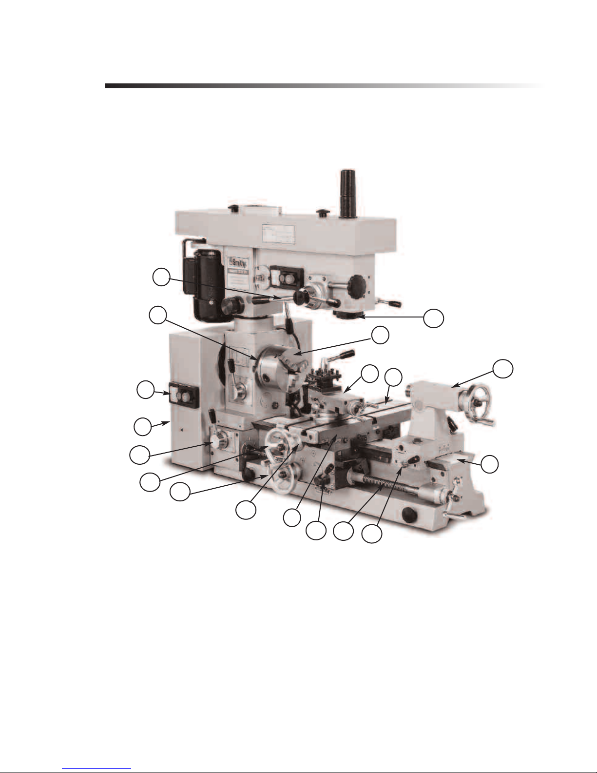
Basic Par ts of the MI-1220 LTD
Learn the operation of your machine, you have to know the names and functions of its
basic units.
5
8
13
9
3
4
18
6
7
17
1
16
15
12
2
14
10
11
Figure 4.1 Midas 1220 LTD
1. Bed. The bed is the machine’s foundation. It is heavy, strong, and built for absolute
rigidity. The two ways on the top are the tracks on which the carriage and tailstock
vel. To maintain an exact relationship between tool point and work piece from one end
a
tr
of the machine to the other, the ways must be absolutely true and accurately aligned to
the line of centers and to one other.
2. Carriage. The carriage consists of the saddle and apron. It moves by hand or power
along the bed, carrying the cr
support the cut
into place by tightening the carriage lock with the setscrew on the backside of the
carriage.
ting tool rigidity and move it along the bed for different operations. It locks
ide, compound rest, and toolpost. Its function is to
oss sl
.smithy.com
isit www
Or V
4-1
Page 13

Midas 1220 LTD Operator’s Manual
3. Compound Rest. Mounted on the cross slide, the compound rest swivels to any angle
horizontal to the lathe axis to produce bevels and tapers. Cutting tools fasten to a
toolpost on the compound rest. The calibration on the front of the base are numbered in
degrees from 60 right to 60 left.
4. Cross Slide. The T-slotted cross slide moves crosswise 90 degrees to the lathe axis by
manual turning of the cross feed screw hand wheel. It also serves as the milling table.
5. Drill Press and Fine Feed Clutch. Pushing in the drill press clutch (engages the fine
feed). To work the clutch, release the spring tension by rotating the drill press handles
clockwise. Pull the clutch out to sue it as a drill press or push it in to use the fine feed.
Use the fine fee hand wheel to move the quill up and down.
6. Forward/OFF/Reverse Switch. This is the main switch used to operate the lathe. It is
simply a forward/reverse switch for the motor. The motor turns counterclockwise for
normal lathe operation and clockwise for normal milling and drilling operation. The
MI-1220 LTD has two switches, one located on the millhead and one on the right side of
the gearbox.
7. Gearbox. The gearbox houses the belts that deriv
e the spindle and change gears for
the powerfeed. Select the thread pitch (for threading) or the feed rate (for turning) by
changing the four change gears on the right side of the gearbox.
8. Headstock. The headstock, which is secured to the bed, houses the gears the drive
the powerfeed and the taper that secure the lathe spindle.
9. Lathe Spindle. The end of the lathe spindle facing the tailstock is the spindle nose. The
spindle nose, which has an MT4 taper, rotates the work piece and drives the lathe chicks
and other workholding devices. Al
l attachments (like three-jaw chucks, four-jaw chucks,
faceplates, etc.) bolt to the spindle flange either directly or via an adapter plate.
10. Leadscr
ew.
The leadscr
ew, which runs the length of the bed, moves the carriage for
lathe turning or thread cutting. It works both manually and under power. You can also
use it manually with the mill.
11. Locks. Locks on the cross slide, carriage, quill, and tailstock (two) keep them from
moving. During machining, lock all axes except the one you want to move.
12. Micr
ossf
cr
ometer Contr
eed, drill calibrated in millimeters. The compound feed and crossfeed are
ol and Calibration.
Just inside the handles of the tai
lstock
calibrated in two thousandths, the tailstock in thousandths, the leadscrew in two
thousandths, and the drill press in forty thousandths.
Note: These micr
ometer dial col
This independent motion is cal
slide, tailstock, longitudinal and mill feeds. They let you zero the collars at any point and
read the feed travel from that point on the dial for increased accuracy.
13. Mill Spindle. The mill spindle attaches to the quill, which moves in and out of the
head. The qui
l lock k
l
eeps the qui
milling horizontally. Usually, tools fir into collets that attach through the spindle via
drawbars.
4-2
ound the handle shafts.
e independent
lars can mo
v
led float. The MI
-1220 L
ly ar
TD has floating dials on the cr
ll still when you install or remove tools from it and while
For Assistance: Call Toll Free 1-800-476-4849
oss
Page 14
4: Basic Parts o thef Midas 1220 LTD
14. Half-nut Lever. This lever transmits power to the carriage for threading.
15. Power Longitudinal Feed. Push the lever down to engage the power of the long feed
for general cutting.
16. Power Cross Feed. Push the lever down to engage the cross feed and pull it up to
disengage.
17. Powerfeed Speed Selector. The two-speed selector for powering the leadscrew is on
the front of the headstock. The leadscrew turns twice as fast in the II position as in the
I position.
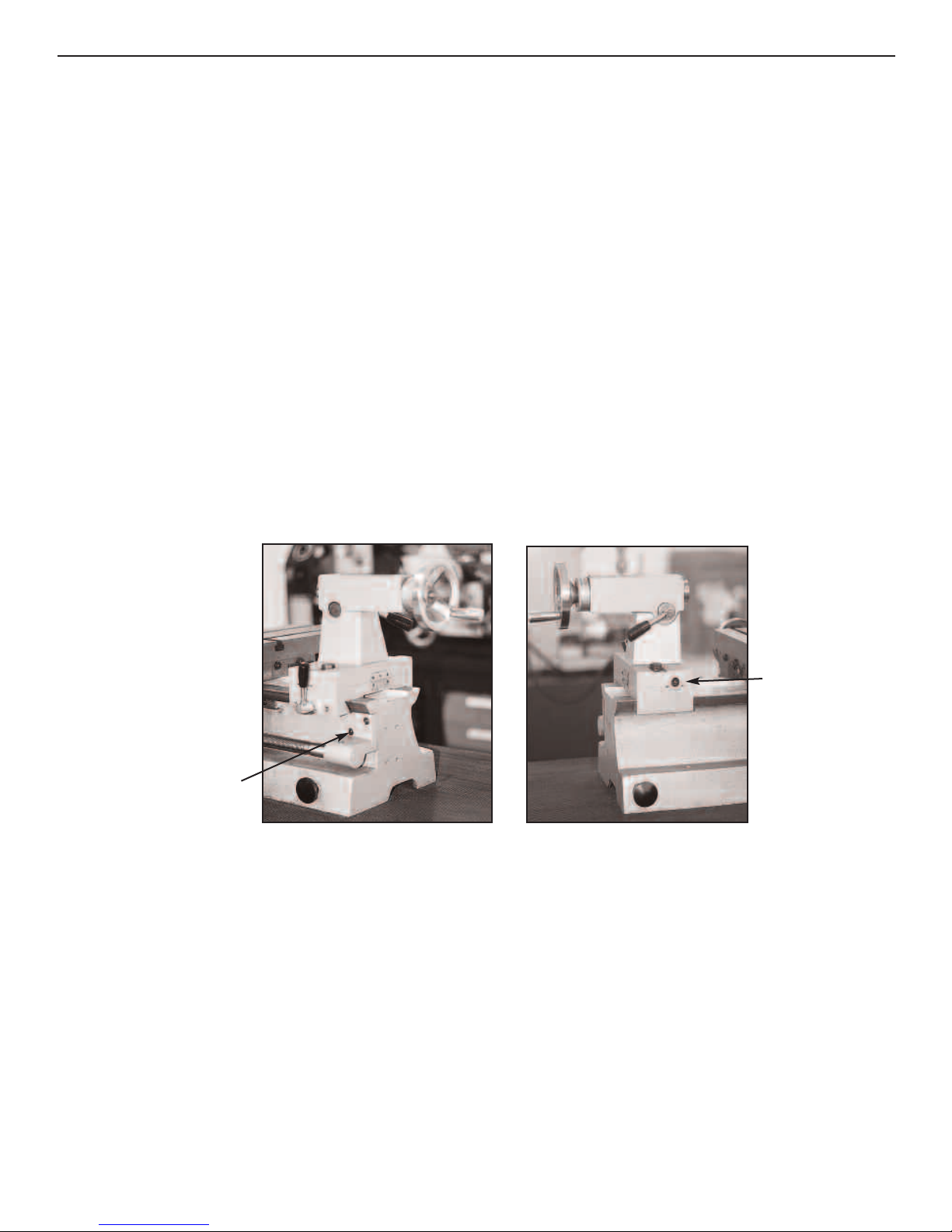
18. Tailstock. The tailstock, which provides right-end support for the work, moves along
the bed and can stop at any point on it. It holds centers, drills, reamers, taps, and other
tools. To move the tailstock spindle, which has an MT3 taper, turn the tailstock hand
wheel. The scale of offset calibrations on the back of the tailstock is in millimeters.
Note: To offset the tailstock, loosed the four base locking bolts. To offset to the left,
loosed the left adjusting bolt and tighten the right and do the same on the other side
.2.
when you want to of
fset to the right. See figur
e. 4
Rgiht
Treslte
Setscrew
Setover
Screw
Figure 4.2 Tailstock base locking bolts.
Or V
isit www
.smithy.com
4-3
Page 15
Chapter 5
Uncrating and Setting Up the MI-1220 LTD
Moving the Machine
Moving a machine tool can be dangerous. Improper techniques and methods may injure
you and/or damage the machine. To find a professional to move and site your Smithy
machine, look in your local Yellow Pages under “Machine Tools, Moving and/or Rigging”.
If there is no such listing or your community does not have a rigging specialist, a local
machine shop or machinist may be able to provide referral.
When you pick up the machine at the shipping terminal, bring a crowbar, tin snips for
cutting the metal straps, and a hammer. If there is obvious shipping damage to the crate,
you’ll be able to inspect the machine before signing for it. Note any damage on the bill
of lading (shipping document). Fill out the claims forms and notify both Smithy Co. and
the shipping terminal about the damage. Failure to notify both parties can complicate
and/or invalidate a claims process.
Trucking company terminals usually have forklifts to assist customers. It’s most
convenient to transport the machines in trucks without canopies and large vans.
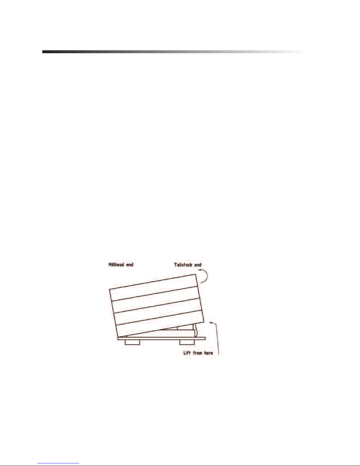
Uncrating and Positioning the Machine
Figure 5.1 Tip the crate from the tailstock end up and over the machine.
The machine is assembled, inspected, and ready to do in its stand. It’s wrapped in a water
and greaseproof cover, strongly braced, and crated. A box of accessories is also in the
crate.
The metal bands that encir
gloves, cut the metal bands with tin snips.
5-1
cle the cr
For Assistance: Call Toll Free 1-800-476-4849
ate are under tension. Wearing eye protection and
Page 16
5: Uncrating and Setting Up the MI-1220 LTD
Caution
The cut edges are sharp. The bands secure the crate top to the base.
After removing the straps, lift off the crate top. Tip the crate from the tailstock end up
and over the machine (Figure 5.1). Do not damage the crate. You may need it another
time to transport the machine.
Once your crate cover is removed it is time to put your machine on its bench. The
machine is just less than 500 pounds so make sure you have some extra hands to help.
There are four lifting pints that pull out from the bed of the lathe. You can use chains or
a tow rope to wraparound these pins and the aid of a lifting device such as an engine
hoist to list the machine on to a bench rated to support the machine’s weight.
Without a mechanical device to aid in your lifting you can lighten the machine by
removing a few or all of the following:
Millhead
1. Remove the four hexagon socket-head screws at the base of the millhead support
column. If a scr
remove it too.
2. Lock the millhead-locking handle.
3. Lift the millhead and column off the lathe head. You may have to rock it back and forth
while lifting it. Make sure that the mill head is locked to the column before removing the
millhead.
ew runs through the belt box into the flange of the support column,
Tailstock
1. Loosen the tailstock lock and pull the tailstock off the end of the bed. The gib and
all out. Be careful no to lose them.
l f
locking pin wi
l
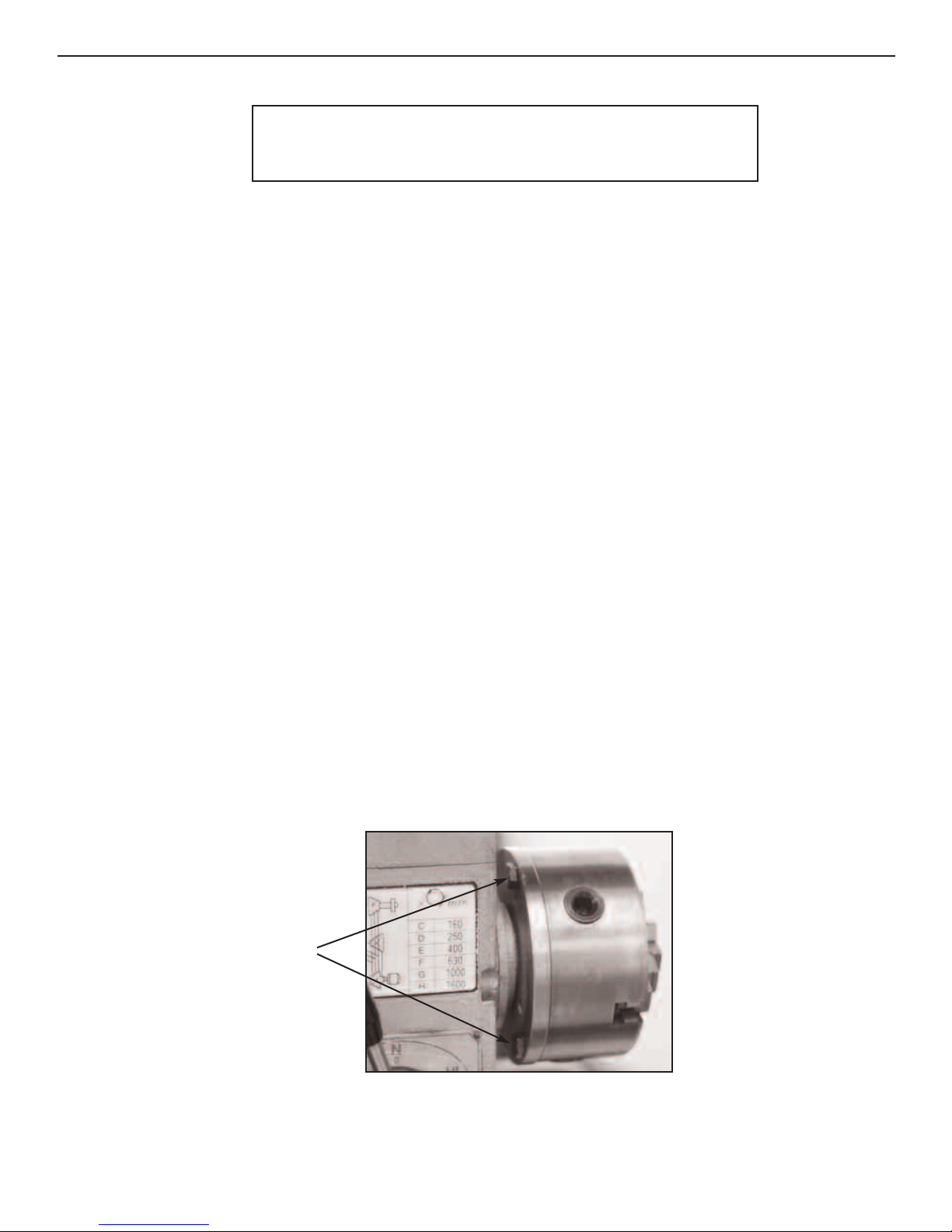
Bolts
Figure 5.2 The chuck attaches to the spindle flange with three bolts.
The one bolt located on the other side of the spindle does not show.
Or V
isit www
.smithy.com
5-2
Page 17
Midas 1220 LTD Operator’s Manual
Three-Jaw Chuck
1. Remove the three bolts behind the chuck that hold it to the spindle flange (Figure 5.2).
The chuck will come off. Don’t let it fall onto the ways. Placing a board between the chuck
and ways will protect the ways.
Place the machine on a strong, rigid table 40” long, 24” wide and 28” to 33” high. We
recommend you to bolt down the MI-1220 LTD machine using the holes in the base of
the bed or using the lifting handles as they held the machine to the shipping pallet.
Selecting a Location
There are several major considerations for selecting a location for your Smithy.
Operation is from the apron side, so allow at least 40” to 48” clearance in front of the
machine.
The machine should be on a 20supply. Try not to use an extension cord. If you must use one, check with an electrician
about the proper size.
Provide ample working light over the operator’s shoulder.
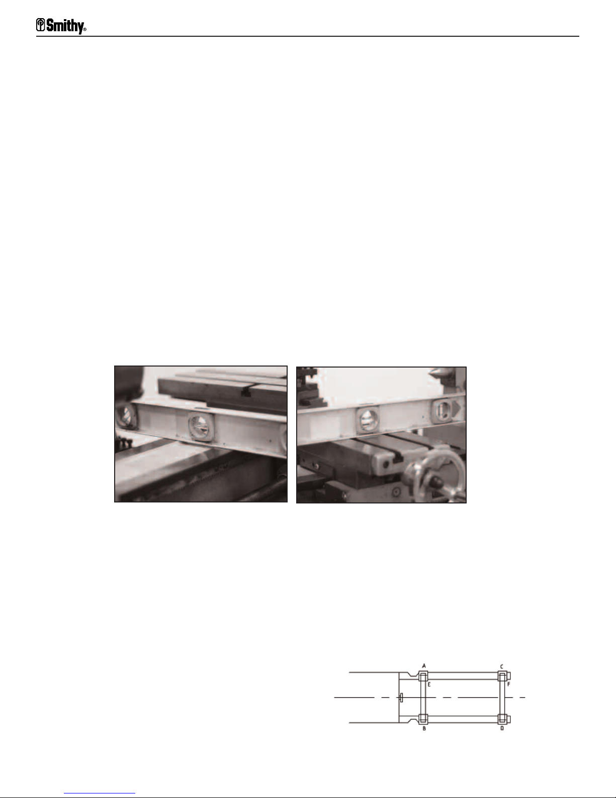
Figure 5.3 Check along and across the bed to make sure it is level.
Place the machine on a solid foundation, concrete if possible. If you must put it on a
wood floor, make sure it is adequate. Brace it if necessary to prevent sagging or settling.
amp circuit, positioned as close as possible to the power
e allowances at the back of the machine tool as at its end and above it for later
Mak
addi
tions, at
stock to be fed through the spindle. If you are considering placing more than one machine
in an area, allow enough floor space to feed long bar stock to each machine.
tachments, and/or accessories. Provide clearance on the left end for bar
Notice To check bench and bed level accuracies,
successively place level at A, B, C, D
(longitudinal positions) and E and F (transverse
positions). Bedways alignment in the longitudinal place
should be better than 0.0016/40”; alignment in the
traverse plane should be better than 0.0024/40”.
5-3
For Assistance: Call Toll Free 1-800-476-4849
Page 18

5: Uncrating and Setting Up the MI-1220 LTD
Cleaning and Lubricating the MI-1220 LTD
Smithy machines are shipped with protective grease coating called cosmoline. Use
WD-40 or non-corrosive kerosene to remove the cosmoline.
Once you have your MI-1220 LTD set up and positioned correctly, you are ready for
lubricating. You must do this carefully and thoroughly before starting the machine. Use a
pressure oil can and a supply of good quality SAE No.10 weight oil.
To be thorough and complete, follow this routine:
Oiling the Ways
Run the carriage as far to the left as possible. Put a few
drops of oil on the ways. Run the carriage to the extreme
right and repeat. You may want to use Way Lube, special
oil formulated for the ways.
Oiling the Millhead Quill
Using your mill handles or your fine feed crank to lower
the mi
work it down and up until it runs smoothly.
llhead down. Apply a thin layer of oil to the quill and
Oiling the Headstock
Figure 5.4 Oiling the ways
Figure 5.5 Oiling the
Millhead Quill
Figure 5.6 Oil the button behind the D gear.
.smithy.com
isit www
Or V
5-4
Page 19
Midas 1220 LTD Operator’s Manual
Open the gearbox door to expose the pick-off gears. Oil the button in the casting behind
the D gear. Then put a few drops of oil on the teeth of all the gears. Grease the zerk on
the A gear shaft.
Check the sight glass under the chuck. If necessary, add oil until it is half full. The oil fill
plug is at the back of the headstock above the motor. Be careful not to overfill it. The
gearbox requires only 8 to 10 ounces of oil.
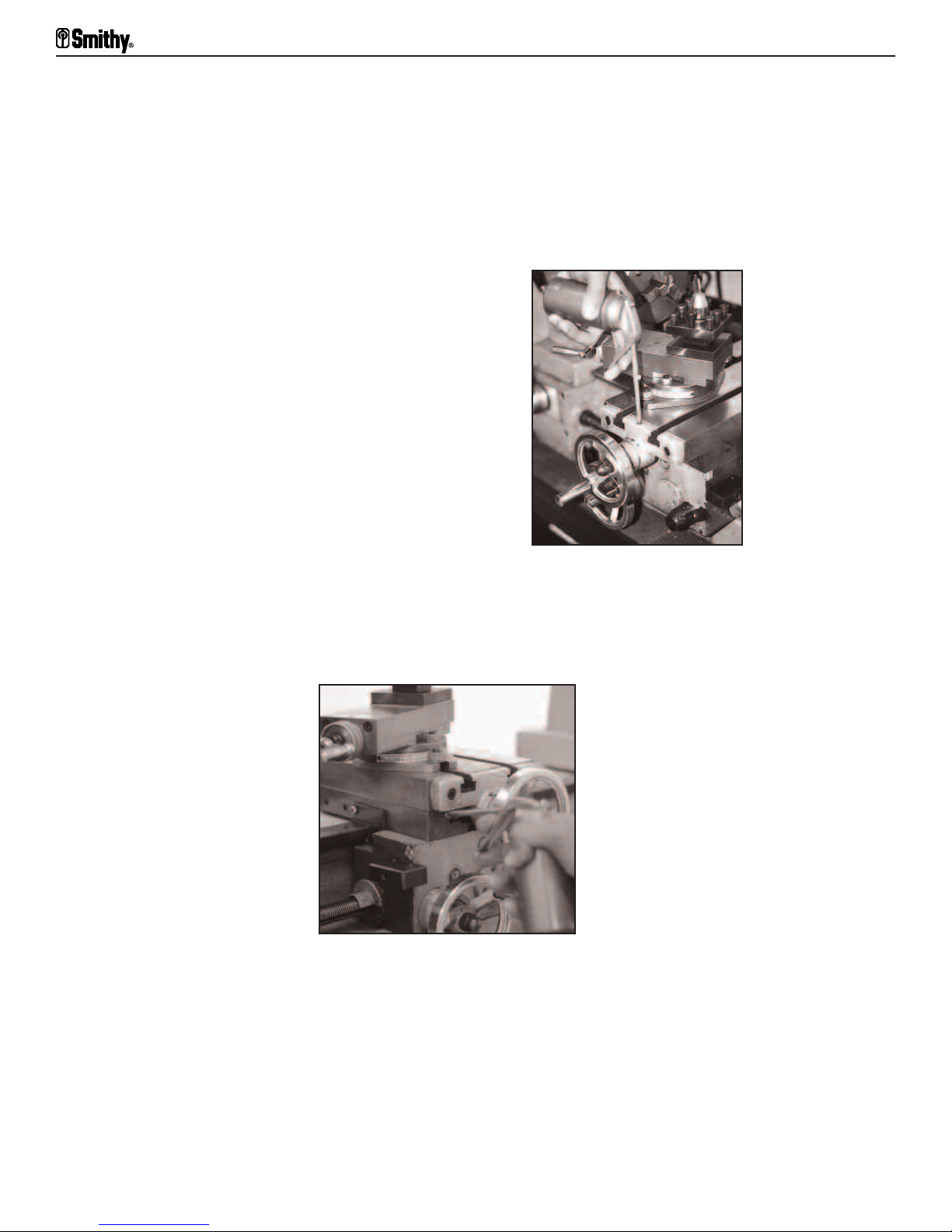
Oiling the Carriage
Lubricate the oil buttons in the cross feed table.
There are two buttons on the left of the saddle for
the bedways and two on the front of the cross slide
for the cross slide ways.
Oil the button in the center of the cross slide.
Put a few drops of oil on the compound slides.
Oiling the Compound Angle Toolpost
Figure 5.8 Oil the buttons along the cross feed table.
l two buttons on top of the compound angle toolpost.
Oi
Figure 5.7 Oiling the table
Oiling the Apron
Put oil in the button just behind the cross slide hand wheel.
5-5
For Assistance: Call Toll Free 1-800-476-4849
Page 20
P
ut oil on the button at the back of the cross slide.
Oiling the Leadscrew
Put oil in the oil buttons on the left trestle.
Put oil in the support for the right end of the leadscrew.
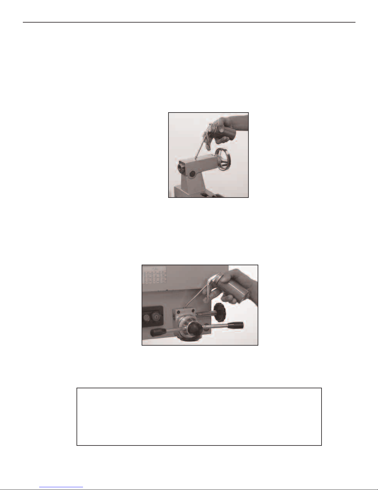
Oiling the Tailstock
5: Uncrating and Setting Up the MI-1220 LTD
Figure 5.9 Oil the two buttons on the top of the tailstock.
Oil the buttons on top of the tai
lstock.
Oiling the Mill/Drill Clutch
Figure 5.10 Oil the clutch housing button.
Put oil in the button on top of the clutch housing.
To keep your machine in peak condition, lubricate it daily after removing any debris.
Do not fill the gearbox sight glass more than half way. Too much oil will make the
motor lug and sling oil out form behind the chuck and inside the belt box.
Or V
isit www
Notice
.smithy.com
5-6
Page 21
Midas 1220 LTD Operator’s Manual
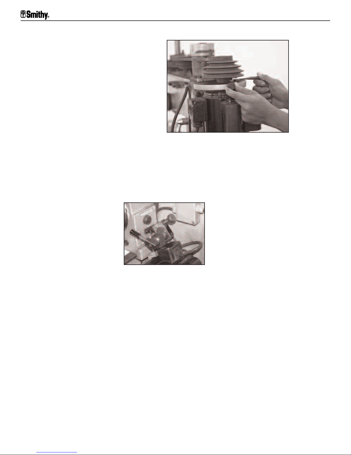
Adjusting Belt Tension
The MI-1220 LTD has two belt tensioners
installed by the factory. One for the
millhead and the other one for the pulley
box.
Figure 5.11 Mill belt
Mill
Locate the “L shaped” lever and a thumbscrew at the top of the mill motor. Loosen the
thumbscrew and then rotate the lever to increase or decrease the belt tension.
Re-tighten the thumbscr
ew when the desired tension is achieved.
Figure 5.12 Lathe belt tensioner.
Lathe
Locate the belt tensioner handle on the motor mount. To tighten the lathe belts, move
the tensioner handle upward so that the handle points toward the lathe head. Turn the
knurled knob clockwise to tighten the bel
t and counter
clockwise to loosen it.
Adjusting the Gibs
The MI-1220 LTD machines have straight gibs. Before using the machine, adjust the gibs
evenly. First tighten the screws all the way. This will lock the movement. Then loosen
each screw one quarter turn and check it. Tighten the gib, the more accurate it will be.
es the tolerances.
v
ving and pol
emo
R
With the gibs properly adjusted, review the following instructions on how to reduce the
backlash, or lost motion in the screw, which also depends on the type of job you’re doing
and/or individual preference.
5-7
ishing the gibs also impr
For Assistance: Call Toll Free 1-800-476-4849
o
Page 22

5: Uncrating and Setting Up the MI-1220 LTD
Reducing Backlash
Backlash of 0.008-0.015” as measured on the dial is normal. If you have more backlash
than that in your crossfeed table, refer to the schematics at the back of this manual, if
necessary and follow these directions:
1. Tighten the cap nut in the center of the cross feed hand wheel securely.
2. Tighten the set screw inside the T-slot so the brass nut cannot move.
3. Tighten the screw in the base of the brass nut. This will remove play between the
threads in the cross feed screw and nut. Do not over tighten it or there will be excess
wear on the nut.
If there is still excess backlash, place one or more shim washers between the large
shoulder of the cross feed screw and the bush bearing. Ask a Smithy technician about our
antibacklash shim washer kit, Item number K99-190.
Figure 5.13 To reduce backlash, tighten the setscrew so the
bush bearing will be secured.
To install shims, turn the hand wheel clockwise to move the cross table away from the
screw seat. Loosen the setscrew. Then pull out on the hand wheel until the bush bearing
is free of the seat. Remove the cap nut, hand wheel, dial, keys, and bush bearing. Install
one or mor
e shim washers and reassemble.
Running in the MI-1220 LTD
thy machines are run at the factory and again before shipping, it is wise
Though al
l Smi
to put your machine through a break-in run before putting it to work. After oiling the
machine, check the belts to make sure the tensioners are correct. Do not plug your
machine yet.
Follow these steps:
Millhead Run-in
1. Make sure that the power switch for the lathe motor and the mill motor are both in the
tion.
f posi
of
2. Close the door of the gearbox before starting your machine.
3. Plug the machine into a grounded 20-amp circuit.
Or V
isit www
.smithy.com
5-8
Page 23

Midas 1220 LTD Operator’s Manual
4. Start the mill motor by pushing in the green start button. After a few minutes, push in
the red stop button and allow the motor to stop. Flip the yellow switch cover and switch
it to the opposite position and repeat the above procedure.
5. Start the lathe by pushing the green button on the lathe control panel.
6. Engage the half nut by pushing down the half nut handle, pull up to disengage. Do the
same with the cross feed and the longitudinal feeds.
7. Push the lathe stop button and allow the motor to stop. Move the direction selector to
the left and flip the yellow cover and switch the red toggle switch to the opposite
position and repeat the above procedure.
During the run-in, try all of the controls. Get a feel for your machine before you start to
work.
Caution
This machine is equipped with power crossfeed and longitudinal feed.
Caution must be taken to not run the power feeds past their limits of travel. As part of
normal operation procedures, run each axis through the entire length of the proposed
machining oper
travel to accomplish the desired task. Failure to do so could result in running one of the
power feeds to the end of its mechanical limits. This is what is known as a “CRASH”. A
ash can cause damage to the work piece and severe damage to the machine.
cr
Remember that becoming familiar with your machine is the best safety insurance you can
have.
ation bef
ore engaging any of the power feeds to assure there is sufficient
Lathe Run-in
1. Start the lathe by pushing the green button on the lathe control panel.
2. Engage the half nut by pushing down on the half nut handle, pull up to disengage. Do
the same with the cross feed and the longitudinal feeds.
3. Push the lathe stop button and allow the motor to stop. Move the direction selector to
the left and flip the yellow reversing switch to the opposite position and repeat the above
ocedure.
pr
During the run-in, try all of the controls. Get the feel for your machine before you start
to work.
5-9
For Assistance: Call Toll Free 1-800-476-4849
Page 24
5: Uncrating and Setting Up the MI-1220 LTD
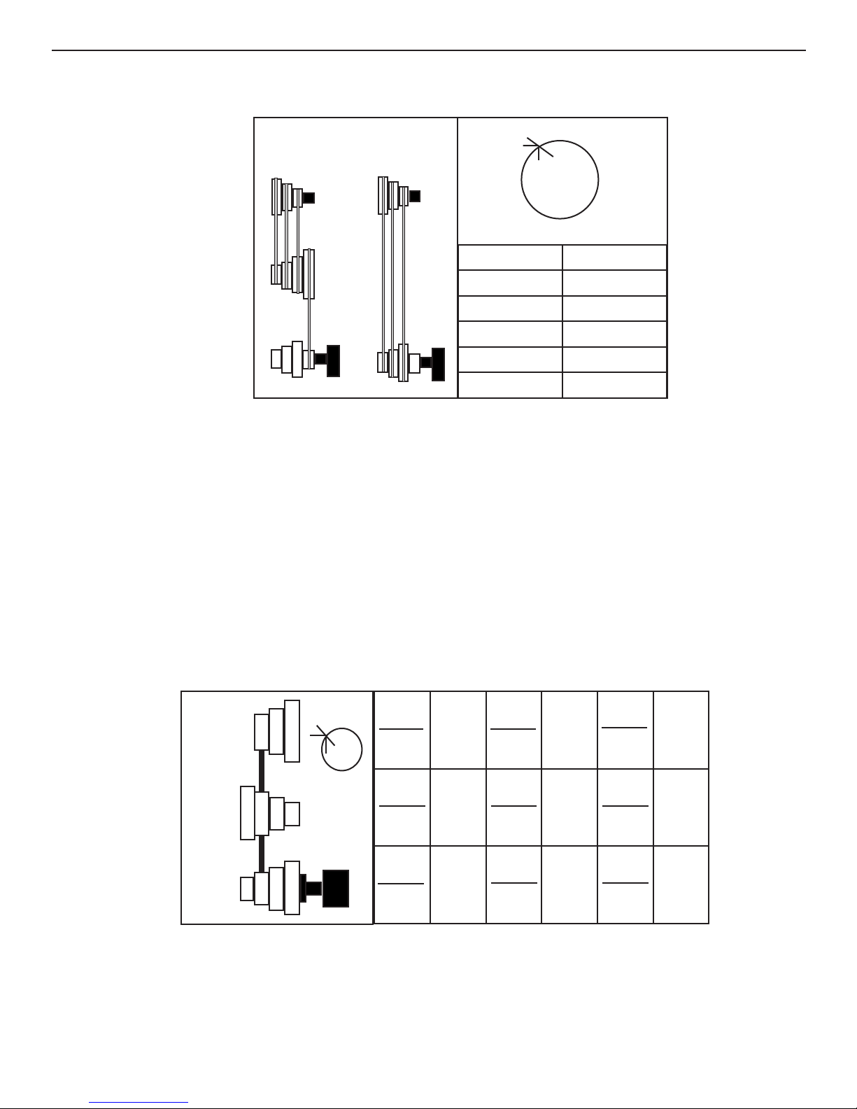
Setting Lathe and Mill Speeds for the MI-1220 LTD
LOW HIGH
C D E
F G H
X
C 160
D 250
E 400
F 630
G 1000
H 1600
Figure 5.14 Setting Lathe Speeds (RPM)
Changing belts changes lathe speeds. The lower speeds use the two short belts. There is
only one position for the motor pulley to idler pulley belt. It goes on the smallest sheave
of the motor pulley (behind the largest sheave, Figure 5.14) and on the largest sheave of
the idler pulley. For 160 RPM, se the idler pulley to lathe spindle pulley belt on the
smallest sheave of the idler pulley to the largest sheave of the spindle pulley (position C).
Move it in once sheave for 250 RPM (position D) and one more for 400RPM (position E).
For the higher speeds, remove the two small belts and use the single long belt from the
motor pulley to the spindle pulley. For 630 RPM (position F), run the belt from the outside sheave (closest to the door) on the motor pulley. Move it one sheave for 1000 RPM
(position G). For 1600 RPM (position H), run it from the largest motor pulley sheave to
the smallest spindle pulley sheave.
C
321
A4 X B1
B4 C1
315
A3 X B1
B3 C1
630
A2 X B3
B2 C3
1250
X
A4 X B2
B
4
2
1
3
A
4
321
B4 C2
A4 X B3
B4 C3
400
500
A2 X B1
B2 C1
A3 X B2
B3 C2
800
1000
A1 X B2
B1 C2
A1 X B3
B1 C3
1600
2000
Figure 5.15 Setting Mill/Drill Speeds (RPM)
Set mill speeds using various combinations of the mill belts. For 315 RPM, place belt A/B
in posi
mo
tion 4 and bel
e the B/C belt to position 3.
v
t B/C in posi
tion 1. For 500 RPM, leave belt A/B belt in position 4 and
Or V
isit www
.smithy.com
5-10
Page 25

Chapter 6
Turning
The lathe rotates a workpiece against a cutting edge. With its versatility and numerous
attachments, accessories, and cutting tools, it can do almost any machining operation.
The modern lathe offers the following:
• The strength to cut hard, tough materials
• The means to hold the cutting point tight
• The means to regulate operating speed
• The means to feed the tool into or across, or into and across, the work, either
manually or by engine power, under precise control
• The means to maintain a predetermined ratio between the rates of rotating
works and the travel of the cutting point or points.
Turning Speeds
When metal cuts metal at too high a speed, the tool burns up. You can machine soft
metals like aluminum at fast speeds without danger or trouble, but you must cut hard
steels and other metals slowly
You must also consider the diameter of the workpiece (Figure 6.1). A point on a 3"
diameter shaft will pass the cutting tool three times as fast as a point on a 1 " diameter
shaft rotating at the same speed. This is because the point travels a tripled
ence.
er
cumf
cir
For work in any given material, the larger the diameter, the slower the speed in spindle
revolutions needed to get the desired feet-per-minute (fpm) cutting speed.
Lathes cut thr
ator's needs. The MI
oper
In thread cutting, the carriage carries the thread-cutting tool and moves by rotating the
leadscrew . The basic principle is that the revolving leadscrew pulls the carriage in the
desired direction at the desired speed. The carriage transports the toolrest and the
eading tool, which cuts the scr
thr
eads in v
arious numbers per inch of material thr
.
-1220 L
ding to the
eaded, ac
TD cuts metric threads and inch threads standards.
ew thr
ead into the metal being machined.
cor
The faster the leadscrew revolves in relation to the spindle, the coarser the thread. This
is because the threading tool moves farther across the revolving metal with each
workpiece revolution.
6-1
For Assistance: Call Toll Free 1-800-476-4849
Page 26

The lathe spindle holding the workpiece revolves at a selected speed (revolutions per
minute, or rpm) according to the type and size of the workpiece. The leadscrew, which
runs the length of the lathe bed, also revolves at the desired rpm. There is a definite and
changeable ratio between spindle and leadscrew speeds.
FPM 50 60 70 80 90 100 110 120 130 140 150 200 300
6: Turning
DIAM
1/16”
1/8”
3/16”
1/4”
5/16”
3/8”
7/16”
1/2”
5/8”
3/4”
7/8”
1”
1-1/8”
RPM
3056 3667 4278 4889 5500 6111 6722 7334 7945 8556 9167 12229 18344
1528 1833 2139 2445 2751 3056 3361 3667 3973 4278 4584 6115 9172
1019 1222 1426 1630 1833 2037 2241 2445 2648 2852 3056 4076 6115
764 917 1070 1222 1375 1538 1681 1833 1986 2139 2292 3057 4586
611 733 856 978 1100 1222 1345 1467 1589 1711 1833 2446 3669
509 611 713 815 917 1019 1120 1222 1324 1426 1528 2038 3057
437 524 611 698 786 873 960 1048 1135 1222 1310 1747 2621
382 458 535 611 688 764 840 917 993 1070 1146 1529 2293
306 367 428 489 550 611 672 733 794 856 917 1223 1834
255 306 357 407 458 509 560 611 662 713 764 1019 1529
218 262 306 349 393 426 480 524 568 611 655 874 1310
191 229 267 306 366 372 420 458 497 535 573 764 1146
170 204 238 272 306 340 373 407 441 475 509 679 1019
1-1/4”
1-3/8”
1-1/2”
1-5/8”
1-7/8”
2-1/4”
2-1/2”
2-3/4”
Table pr
account. Determine the desir
machine.
153 183 216 244 275 306 336 367 397 428 458 612 918
139 167 194 222 250 278 306 333 361 389 417 556 834
127 153 178 204 229 255 280 306 331 357 382 510 765
117 141 165 188 212 235 259 282 306 329 353 470 705
102 122 143 163 183 204 224 244 265 285 306 408 612
2”
95 115 134 153 172 191 210 229 248 267 287 382 573
85 102 119 136 153 170 187 204 221 238 255 340 510
76 91 107 122 137 153 168 183 199 214 229 306 459
69 82 97 111 125 139 153 167 181 194 208 278 417
3”
64 76 89 102 115 127 140 153 166 178 191 254 371
Table 6.1 Cutting Speeds for Various Diameters
vides exact speeds (rpm). It does not tak
o
e machine speed l
ate of speed and find the closest speed a
ed r
tations into
imi
vailable on your
Or V
isit www
.smithy.com
6-2
Page 27

Midas 1220 LTD Operator’s Manual
• The means to hold the cutting point tight
• The means to regulate operating speed
• The means to feed the tool into or across, or into and across, the work, either
manually or by engine power, under precise control
• The means to maintain a predetermined ratio between the rates of rotating
works and the travel of the cutting point or points.
Gear ratios
The lathe lets you use various indicated gear combinations to cut the desired number of
threads per inch (TPI), or the metric equivalent, or to advance the tool a specified amount
each revolution (feed rate expressed as inches per revolution [ipr]).
The MI-1220 LTD has pick-gear gearboxes; gears are picked and placed to change the
gear ratios. The gearbox mechanism determines the leadscrews rotation rate in relation
to the spindles f
gears per Figure 6.2.
or threading, turning, and facing. To change the feed rate, replace the
e 6.2 (missing)
Figur
6-3
For Assistance: Call Toll Free 1-800-476-4849
Page 28

Chapter 7
Metal Theory
Tool sharpness
Instead of being the all-important factor in determining tool performance, keenness of
the cutting edge is just one of many factors. On rough or heavy cuts, it is far less
important than strength, because a false cutting edge or crust usually builds up on the
tool edge, and though the edge dulls, its angle often increases the cutting tool's
efficiency by increasing its wedging action. Cutter shape is usually more important than
edges, which generally are rough-ground and usually must be honed for fine finishing
cuts or work in soft, ductile materials like brass or aluminum.
Lack of clearance, which lets a tool drag on the work below the cutting edge, is a brake
e on the cutting point and interfering with tool
ly reducing pr
on the lathe, gr
performance more than edge dullness. At the same time, excessive clearance weakens a
tool because of insufficient support to the cutting edge. Such an edge will break off if you
use the tool on hard materials.
Clearance requirements change with almost every operation, but there are certain
standar
cutting edge; there must also be end and side clearance. To help the chip pass with
minimum resistance across the top of the tool, i
determine the shapes and rakes to which you'll grind your tools by the tool holder you
use. TheCB-1220 XL LTD have a four-sided turret toolpost that accommodates four
high-speed-steel (HS
ds for all aspects of the cutting tool. You must not only provide clearance from the
eat
S), carbide-tipped, or indexable carbide turning tools.
essur
t should often have top r
ake as well. You
Heat
The ener
the ener
ceramic tools, this heat created a serious machining problem. Machining could be done
only under a steady flow of coolant, which kept the tool from heating to its annealing
point, softening, and breaking down.
th HSS, you can usually cut dry unless a small lathe is running at extremely high speeds
Wi
on continuous, hea
hot. They do not dissipate the heat, however, or in any way prevent the workpiece from
heating up. Because steel expands when heated, it is a good idea, especially when
working on long shafts, to check the tightness of the lathe centers frequently and make
sur
gy expended at the lathe's cut
gy expended is great, the heat is intense. Before today's HSS, carbide, and
vy-duty production work. HSS tools are self-hardening even when red
e workpiece expansion does not cause centers to bind.
ting point con
.smithy.com
isit www
Or V
verts largely into heat, and because
7-1
Page 29

Midas 1220 LTD Operator’s Manual
Low-Carbon
Steel
Speed (sfm)
Roughing
Finishing
90
120
Feed (ipr)
Roughing
Finishing
0.010-0.202
0.003-0.005
Table 7.1 Cutting Speeds and Feeds for High-Speed-Steel Tools
High-
Carbon
Steel
Annealead
50
65
0.101-0.020
0.003-0.005
Alloy Steel
Normalized
45
60
0.010-0.020
0.003-0.005
Aluminum
Alloys
200
300
0.015-0.030
0.005-0.010
Cast Iron Bronze
70
80
0.010-0.020
0.003-0.010
100
130
0.010-0.020
0.003-0.010
In everyday lathe operations like thread cutting and knurling, always use cutting oil or
other lubricant. On such work, especially i
a brush in oil occasionally and holding it against the workpiece will provide sufficient
lubrication. For continuous, high-speed, heavy-duty production work, however, especially
on tough al
essential if you're using a non-HSS cutting tool.
When you use coolant, direct it against the cutting point and cutter. Consider installing a
coolant system if you don't have one.
Table 7.1 lists cutting speeds and feeds for HSS cutters so you can set up safe rpm rates.
The formula is as follows:
rpm=CSx4 / D"
where:
CS = cut
D" = diameter of the workpiece in inches.
To use this formula, find the cutting speed you need on the chart and plug that number
into the CS portion of the formula. After calculating the rpm, use the nearest or next lower
speed on the lathe and set the speed.
loy steels, using a cutting oi
eet per minute (sf
ting speed in surf
ace f
f the cut is light and lathe speed low, dipping
l or coolant will increase cutting efficiency. It's
m)
If you were to make a finish cut on a piece of aluminum 1" in diameter, for example, you
would see the desired sfm per Figure 7.3 is 300. Then:
rpm = 300 sfm x 4 / 1
rpm = 1200 / 1
7-2
For Assistance: Call Toll Free 1-800-476-4849
Page 30

7: Metal Theory
rpm = 1200 or next slower speed.
For high-carbon steel, also 1" in diameter,
rpm = 50 sfm x 4 / 1
rpm = 200 / 1
rpm = 200 or next slower speed.
The four-turret toolpost lets you mount up to four different tools at the same time. You
can install all standard-shaped turning and facing tools with 1" or smaller shanks. The
centerline is approximately 5/8" above the bottom of the turret. Smithy also offers
quick-change tool sets that greatly speed up lathe operations. Contact a Smithy
technician for details.
Or V
isit www
.smithy.com
7-3
Page 31

Chapter 8
Grinding Cutter Bits for Lathe Tools
High Speed Steel Cutters
The advantage of HSS cutter bits is you can shape them to exact specifications through
grinding. This lets you grind a stock shape into any form. Stock shapes come in an
assortment of types, including squares, flats, and bevels. Many shops buy their cutters as
ready-ground or ready-to-grind bits or blades.
Ready-to-grind bits and blades are of specially selected HSS, cut to length and properly
heat-treated. They are fine tools in the rough and generally superior to HSS shapes sold
by the pound.
ou have five major goals:
In grinding HS
• A strong, keen cutting edge or point
• The proper cutting form (the correct or most convenient shape for a specific
operation)
S cutter bi
ts, y
• Front clearance away from the toolpoint
• Clearance away from the side of the tool (side rake)
ee chip movement over the tool and away from the cutting edge.
• Fr
Keenness angles can vary from 60° for mild softness to 90° for hard steels and castings
(Figure 8.1).
Side
Rake
Side Clearance
o
3-10
Angle of
Keenness
Figure 8.1 Keenness angles vary from 60 to 80 degrees.
8-1
For Assistance: Call Toll Free 1-800-476-4849
Page 32

8: Grinding Cutter Bits for Lathe Tools
Front clearance must always be sufficient to clear the work. If it is too great, however,
the edge weakens and breaks off (Figure 8.2). Side and back-rake requirements vary with
the material used and operation performed. Back rake is important to smooth chip flow,
which is needed for a uniform chip and good finish, especially in soft materials. Side rake
directs the chip flow away from the point of cut.
Figure 8.2 The edge weakens if front clearance is too great.
Grind cutters on a true-surfaced, good-quality, medium-grit grinding wheel (preferably an
8", 46-60A-grit or 68A-grit Carborundum wheel) at 6000 or 6500 rpm. When starting with
an ungrounded cutter bit, the procedure (Figure 8.3) is usually to:
1. grind the left-side clearance
2. grind the right-side clearance
3. grind the end form or radius
4. grind the end clear
ance
5. grind the top rake, touching in a chipbreaker.
If you are honing the cutting edge (for fine finishing or machining soft materials), draw
the cutter away from the cutting edge across the oilstone as shown in Figure 8.4.
Cutter Bit
Grinding Wheel
1. Left Side
Clearance
2. Rigt Side
Clearance
3. End
Clearance
4. Radius 5. Top Rake
Figure 8.3 Grinding sequence for an unground cutter bit.
Or V
isit www
.smithy.com
8-2
Page 33

Midas 1220 LTD Operator’s Manual
ilstone
O
Figure 8.4 When honing, draw the cutter away from the cutting edge across the oilstone.
Materials Other Than Steel
As pointed out earlier, when grinding HSS cutters, we determine cutting angles primarily
by strength requirements, not keenness requirements. Angles and rakes for general
industrial shop use are established. In machining steel, the softer the steel, the keener
the angle of the cutting edge. For soft steels, angles as acute as 61° are possible.
Figure 8.5 With soft steels, 61 degree angles are possible.
The same general rule applies to cast iron. Chilled or very hard cast iron requires tools
with cutting-edge angles as great as 85°. For ordinary cast iron, you obtain greatest
efficiency with a more acute cutting edge-approximately 71°.
Figure 8.6 With cast iron, a 71 degree angle is most efficient.
Bits for Turning and Machining Brass
Brass tends to pull or drag when machined. It's best to machine it on dead center with
the top rake in the horizontal plane of the lathe centers. Softer than steel, brass needs
less support f
or the cut
ting edge. Brass cutters require an almost flat top angle and can
8-3
For Assistance: Call Toll Free 1-800-476-4849
Page 34

8: Grinding Cutter Bits for Lathe Tools
gain greater angle keenness only in increased side and end rakes. It is often advisable to
hone the cutting edges of cutters used to machine brass.
Note: All roundnose cutters are ground with flat tops and equal side rakes because they
are fed across the work, to both right and left.
Special Chip Craters and Chipbreakers
When grinding cut-off blades, and occasionally on other cutter bits where the material's
extreme hardness or toughness makes it difficult to control the chip leaving the work, it
sometimes helps to grind a smooth, round crater just behind the cutting edge. This serves
as a chip guide and starts the chip curling smoothly.
Figure 8.7 A crater starts the chip curling smoothly.
Using a Center Gauge to Check V-Thread Forms
It may be convenient to grind a standard cutter bit for thread cutting, especially for
cutting standard 60° V-threads. When grinding an ordinary square cutter into a thread
ting tool, tak
cut
dinary center gauge for a standard V-thread tool or a special thread gauge for special
or
e care to ensur
e a true thread f
thread forms.
To grind a cutter for an ordinary V-thread, grind first the left side of the tool, then the
right side, to 30°. Be careful to grind equally from both sides to center the toolpoint. Then
test for true form by inserting the newly ground point in the closest-sized V in a standard
center gauge (Figure 8.8). Examine the gauge and cutter before a light. When the cutter
is ground perfectly, no light streak shows between tool and gauge. Use a grinding chart
es.
or other r
f
ak
orm. The easiest way is to use an
Figure 8.8 Insert the point into the nearest seized V in the center gauge.
Or V
isit www
.smithy.com
8-4
Page 35

Midas 1220 LTD Operator’s Manual
Acme or Other Special Threads
Thread gauges are available for all standard threads. Before grinding such cutters,
ascertain the correct pitch angle of the particular thread profile. For example, the pitch
of an acme thread is 29° to a side, and the toolpoint is ground back square to an exact
thread profile that requires a different end width for each thread size.
Thread forms must be accurate if threads are to fit snugly and smoothly. Every
resharpening of this type of cutter requires regrinding the entire form. It is far better,
when doing any amount of threading, to use a threading tool with a special form cutter.
Sharpening such cutters requires only flat, top grinding, which does not alter the cutting
profile.
Carbide-Tipped Cutters and Cutter Forms
Carbide is a compound of carbon and a metal. In cutting tools, it is usually carbon and
tungsten. The hardness of carbide cutting materials approaches that of diamond. While
carbides permit easy machining of chilled cast iron, hard and tough steels, hard rubber,
Bakelite, glass, and other difficult or "unmachinable" materials, its primary use in
industry is for long production runs on ordinary steels. On such work, carbide-tipped tools
permit higher running speeds and much longer runs between resharpenings. The cutting
edge of carbide tools stands up 10 to 200 times as long as the edge of HSS tools (Figure
8.9).
The advantage of carbide is that it tolerates much higher heat than HSS or other alloys
so you can run at higher speeds. The disadvantage is that it is more brittle than HSS and
must ha
ve adequate support in the toolpost to prevent vibration and breakage.
Application Use Grade
Cast Iron Roughing cuts C-1
Non-ferrous, non-metallic, high-temperature
alloys
200 and 300 Series stainless steels
General purpose C-2*
Light finishing
Precision boring
Roughing cuts
General Purpose
C-3
C-4
C-5
C-6*
Alloy steels Finishing cuts C-7
400 Series stainless steel, high velocity Precision boring C-8
Table 8.1 Carbide Types and Cutting Tool Applications
8-5
For Assistance: Call Toll Free 1-800-476-4849
Page 36

Chapter 9
Setting Up Lathe Tools
After selecting a cutter, insert it in the toolholder. Allow the cutter bit to project just
enough to provide the necessary clearance for the cutting point. The closer the cutter is
to the toolpost, the more rigid the cutting edge. Allen-head capscrews hold the tool in the
toolpost. To assure maximum rigidity, don't let the tool extend too far beyond the end of
the toolpost turret.
Cutting Tool Height
After inserting the cutting tool into the toolpost, adjust the height of the cutting edge in
relation to the lathe center. Insert a center in the tailstock. Then run the tool and center
together.
The cutting edge on the tool should meet the point on the center. It may be necessary
to use shims, which can be of various thicknesses and materials (Figure 9.1). Many
seasoned cutting-tool height machinists use pieces of old hacksa
toolbit is too high, shim the back of the toolbit. If it's too low, shim the entire tool.
w blades as shims. If the
Figure 9.1 Placing shims under the tool can correct cutting too height.
Turning Tools
For general turning operations, set the point of the cutter bit slightly above the
centerl
9.2, left).
Exceptions are soft brass, aluminum, and materials that tend to pull or tear. When
machining these materials, set the cutter on dead center (Figure 9.2, right).
ine of the work. I
n steel, the har
isit www
Or V
der the material, the less abo
.smithy.com
e center (Figur
v
e
9-1
Page 37

Midas 1220 LTD Operator’s Manual
Figure 9.2 The harder the steel (left),the less above center you set the cutter point.
For soft brass and aluminum (right), set the cutter on dead center.
When cutting toward the headstock on most turning and threading operations, swing the
compound rest to hold the shank of the toolholder at an angle. The angle should be
approximately 29-1/2° left of perpendicular to the line of centers, except for extremely
heavy, rough-forcing cuts close to the limits. For such work, use a straight-shanked tool
held perpendicular to the line of lathe centers in the right side of the toolpost. The tool
will tend to swing out of the cut rather than hog into the work if you reach a stalling
point.
Figure 9.3 The tool will swing out of the cut (left) rather than hog into the work (right)
if you reach a stalling point. Note the tool is in the right-hand side of the toolpost.
Threading Tools
eading tools should alw
Thr
l affect the thread profile (Figure 9.4).
below wi
9-2
l
y deviation above or
ys engage the work on dead center
a
. An
Figure 9.4 Threading tools engage the work on dead center.
For Assistance: Call Toll Free 1-800-476-4849
Page 38

9: Setting Up Lathe Tools
Cutoff, Thread Cutting and Facing Tools
For cutoff, thread cutting, and facing, feed the cutter to the work on dead center (Figure
9.5). For the beginner, the average feed should not exceed 0.002 inches per revolution
(ipr).
Chip Curve
Figure 9.5 Feed the cutter on dead center for cutoff, thread cutting and facing.
Boring and Inside Threading Tools
For boring and inside threading, the cutter point engages the work on dead center (Figure
9.6). For greater cutting efficiency, position the bar while parallel to the line of lathe
centers sufficient
ly below center to give the cutter a 14-1/2 degree approach angle. For
internal threading, grind the top face of the cutter to compensate for this angle, giving a
flat, true form top face.
Some machinists prefer to position the tool slightly above center when boring. With the
bit above center, if a tool chatters it deflects down into empty space instead of into the
workpiece.
Figure 9.6 For boring and inside threading, the cutter point is at dead center.
Or V
isit www
.smithy.com
9-3
Page 39

Chapter 10
Setting Up with Centers, Collets, and Chucks
Before setting work up on centers, make sure the spindle and tailstock centers align
accurately. Do this by inserting a center into the nose spindle and inserting the tailstock
center into the tailstock ram. Then move the tailstock toward the headstock until the
centers touch (Figure 10.1). You can correct any lateral alignment error by adjusting the
tailstock set over screws (Figure 4.8).
Figure 10.1 When aligning spindle and tailstock centers, move the
tailstock toward the headstock until the centers touch.
For most turning operations, work is held in the lathe between the lathe centers by means
of holes drilled in the ends of the stock to be machined. Your machining accuracy depends
primari
Locating these holes is called
ly on how precisely y
ou locate these holes at the center of the bar or block.
centering
.
Centering
You can improve centering greatly by first squaring or facing the ends of the workpiece
(Section 12.1). This gives you a true cross section in which to locate the centering holes.
First, chuck the stock in the appropriate chuck. Let the stock protrude about an inch.
Place a right-hand side tool (or a straight turning tool with a facing cutter) in the
ly adjust the cut
ul
toolpost. Car
the toolpost. If you don't do this, a small tit or projection will remain in the center of the
stock and perhaps cause the center drill to run off center.
Start your lathe on the slowest speed. Bring the tool into the cutting position against the
center of the workpiece. F
yourself, using the hand cr
end roughened by the hacksaw. After facing one end, reverse the work and face the
opposite end.
ef
ossf
ting edge so i
eed the tool f
eed. One or two light cuts is usually enough to true up an
t is exact
om the center of the stock outw
r
ly on center, then tighten it into
d, tow
ar
ard
You can center on round stock (Figure 10.2) with calipers, dividers, or special centering
10-1
For Assistance: Call Toll Free 1-800-476-4849
Page 40

10: Setting Up with Centers, Collets, and Chucks
instruments (Figure 10.3). Centering square or rectangular stock is done by scribing lines
from opposite corners. The intersection of these lines is the center (Figure 10.4).
Figure 10.2 Centering on round stock and
Figure 10.4 Centering on square or rectangular stock.
Figure 10.3 Use centering instruments include calipers and dividers.
After locating the center of each end, drive a starting depression for the drill into the stock
th a center punch. Check centering ac
wi
curacy by placing the workpiece between the
spindle and tailstock centers. Revolve the headstock slowly against the tip of a tool or a
piece of rigidly held chalk.
The chalk should touch just the high spots (Figure 10.5). If the center is off 0.002" or
more, correct the position of the center by repunching at an angle.
Chalk Marks
Chalk
Compound
Figure 10.5 When you revolve the headstock against a piece of chalk,
the chalk should just touch the high spots.
Next, drill and countersink the centers to conform to the profile of the lathe centers. This
is best done with a combination center drill/countersink held in the tailstock arbor chuck.
The centers now wi
l
e the lathe centers wi
l tak
Or V
isit www
thout pla
.smithy.com
y or chat
ter.
10-2
Page 41

Midas 1220 LTD Operator’s Manual
If a combination drill is not available, you can drill centers with a small drill and
countersink them with a drill of sufficient diameter ground to a 60° point. A 60° taper is
standard for lathe center points. Correct center depth is given in Figure 10.6. Take care
to get an accurate 60° countersink in the center (Figure 10.7).
Too Shallow
Correct Path
Too Deep
Figure 10.6 The correct depth of center is illustrated above.
If it's too deep (bottom), only sharp outer edges will contact the center
.
Center
Work
Hole
Work
Work
Lathe
A
Center
B
C
Point
Figure 10.7 Counterbore centers with a drill to a 60° point so they fit the lathe centers (A).
Too obtuse (B) or too acute (C) a counterbore will give insufficient bearing,
and destroy the lathe centers.
Mounting Work Between Centers
e the chuck from the lathe, bolt the faceplate to the spindle if l angle (Figure 10.8),
v
emo
R
and put in both headstock and tailstock centers. Fasten a lathe dog (Figure 10.9) to one
end of the work. For ease of operation, use a live or rotating center in the tailstock end
so you won't need lubrication.
Before centers starting the lathe, make sure the centers don't hold the workpiece too
tight
. Heat ma
ly
y cause the workpiece to expand, so w
tailstock center so the work turns freely but without end play.
If, after partially machining the workpiece, you find you must machine the stock under
the lathe dog, remove the workpiece from the lathe and place the lathe dog on the
machined end. Then turn this new tai
diameter or f
orm.
10-3
For Assistance: Call Toll Free 1-800-476-4849
lstock center end of the shaft down to the desir
atch for binding. Adjust the
ed
Page 42

10: Setting Up with Centers, Collets, and Chucks
Figure 10.8 Bolt the faceplate to the spindle flange
Using a Clamp Dog
Standard lathe dogs drive round, or near-round, shapes. Rectangular or near-rectangular
stock requires clamp dogs. In a properly made clamp dog, the under face of the heads
of tightening screws are convex and fit into concave seats, while the holes in the upper
bar are elongated. This design allows a firm grip of off-square shapes without bending
the screws. Top and bottom bars should also have V-notches to give a firm grip on
triangular or other odd-shaped stock. You can use clamp dogs or special V-jaw dogs also
to hold highly polished round bars.
Using Faceplates
For work setup, faceplates serv
centers. Second, they hold workpieces shaped so you can't chuck them or mount them
on centers.
Faceplates for driving workpieces on centers are generally small. They're notched and
slotted to receive the tail of the lathe or clamp dog, bolt drive, or other driving tool
(Figur
e10.9). F
aceplates f
die parts, for example) are usually larger and have varied designs. They may be
T-slotted, drilled all over, or slotted and drilled. Workpieces mount on such faceplates with
-slot or standar
T
d bolts, strap clamps, angle plates, or other standard setup tools.
e two purposes. First, they drive workpieces held between
or holding workpieces (irr
egularly shaped casting, machine, or
Figure 10.9 Fasten a lathe dog to one end of the work piece.
Or V
isit www
.smithy.com
10-4
Page 43

Midas 1220 LTD Operator’s Manual
Note: Before starting to machine work set up on centers, check to see the lathe dog tail
is free in the faceplate slot so it won't lift stock off its true line of centers, as in Figure
10.10. Also, be sure lathe centers fit closely into the center holes to eliminate side play
but not so tightly they bind. If you're working on a long workpiece, check it frequently to
be sure the center does not bind. Also, balance unbalanced setups with counterweights
to overcome any "throw" as the work revolves (Figure 10.11).
Tail of Lathe Dog
Figure 10.10 Make sure the lathe dog tail is free in the faceplate slot
so it won't lift off the true line of centers.
Figure 10.11 Counterweights can help with unbalanced setups.
Setting Up Work on a Mandrel
ou can machine cyl
Y
indrical or bor
by mounting them first on a mandrel (Figure 10.12). Then mount them between centers.
The solid mandrels, which are driven into the hole of the work-piece, must be tight
enough to turn the workpiece against the tool without slippage. Oil them lightly before
driving them into the workpiece. Otherwise, the workpiece may freeze to the mandrel,
making it impossible to r
emo
10-5
ed pipe work or cored castings too long to fit in a chuck
e the mandrel without damaging both workpiece and
v
For Assistance: Call Toll Free 1-800-476-4849
Page 44

10: Setting Up with Centers, Collets, and Chucks
mandrel. When removing a mandrel, drive it back out of, instead of through, the hole.
You can purchase hardened steel mandrels, which have a slight (0.003") ground taper
and an expanding collar, to facilitate mounting and demounting (Figure 10.13). Mandrels
with compressible ends for holding single or ganged pieces are also available. When a
workpiece is mounted on a mandrel, machine it as you would a solid shaft. You can drill
eccentric centers in mandrel ends to permit eccentric turning.
Figure 10.12 Mount workpieces too long for a chuck on a mandrel.
Figure 10.13 Hardened steel mandrels have a slight ground taper and expanding collar.
Steady Rests and Follow Rests
Rests are for setting up (1) work that is relatively long in proportion to its diameter or (2)
work whose dead end must be left f
ree for boring or other operations. You can also use
rests to machine slender shafts that are apt to spring out of alignment from the thrust of
the tool. The purpose of a r
est is to support the workpiece and maintain it in accurate
alignment for machining. Rests are classed as steady rests or follow rests.
Steady Rests
Steady r
thr
of the shaft and keep it from moving out of the line without interfering with the
operation.
o set up a steady r
T
steady rest into position and tighten it to the bed. With the bearing jaws clearing the
work, close the top of the rest and tighten the locking screw. Now, with the lathe
running, adjust the three bearing jaws to touch, but not push, the workpiece. Finally, test
again for alignment, making sure the axis of the workpiece coincides with the axis of the
lathe. Otherwise, the end wi
The tips of the jaws are bronze and require lubrication.
ests mount on the lathe bed (Figure10.14). Clamped over the ways, they provide
ee bearing surf
aces. These surfaces bear down lightly but rigidly against the surface
est, first center the work in the chuck and true it up. Then slip the
ll not be square and the surfaces and boring will be untrue.
Or V
isit www
.smithy.com
10-6
Page 45

Midas 1220 LTD Operator’s Manual
Figure 10.14 Steady rests mount on the lathe bed and provide three bearing surfaces
Follow Rests
Long or slender shafts that are apt to spring out of have a slight ground taper and
alignment by the thrust of the cutting tool often require a follow rest expanding collar.
Follow rests mount on the carriage of the lathe and move with the tool, backing up the
workpiece opposite the point of the tool thrust. They have two adjustable supporting
jaws, one holding the work to keep it from climbing up on the tool and the other behind
the work to counter the thrust of the tool.
Note: Take great care in adjusting the jaws of rests, as they must form a true axial
bearing for the work and let i
Figure 10.15 Follow rests mount on the lathe carriage and move with the tool.
t turn f
reely but wi
thout play.
Setting Up Work in a Chuck
enient
Chucks usual
equiring machining at, into (boring or inside thr
r
possible to set up such work on a faceplate, the convenience of chucks has made them
part of every complete lathe. Lathe chucks come in many types and sizes and hold
workpieces of diameters approaching the swing of the lathe.
ly hold work that is too short to hold con
v
eading), or across its end. While it is
ly between centers or work
dinary use, ther
or or
F
independent lathe chuck has f
to hold round, square, eccentric, or odd-shaped work (Figure 10.16). The three-jaw
universal geared scroll chuck holds only round or near-round work with three, six, nine,
12, or other multiple-numbered sides. It always holds work concentrically. The three-jaw
chuck has the adv
10.17).
e ar
antage of being sel
10-7
e two standard types of headstock chucks. The four-jaw
our holding jaws that can operate independently and adjust
-centering-all jaws move in or out together (Figure
f
For Assistance: Call Toll Free 1-800-476-4849
Page 46

10: Setting Up with Centers, Collets, and Chucks
Figure 10.16 Four-jaw independent lathe chucks hold round, square,
eccentric, or odd shaped workpieces. and Figure 10.17 Three-jaw universal geared scroll
chucks hold round or near-round workpices.
Mounting Work in a Four-jaw Independent Lathe Chuck
For small-diameter, short work, insert jaws in the chuck with high ends to the center. This
es the maximum gripping and tool clearance (Figure 10.18). For large-diameter work,
giv
insert the jaws in the chuck slots with the high steps of the jaws to the outside of the
chuck (Figure 10.19).
To place work in a chuck, follow these steps:
1. Adjust the chuck jaws to the approximate opening to receive the work. Roughly
center them by matching the nearest concentric ring on the chuck face with the
corresponding mark on the jaws.
2. Place the work in the chuck and grip it. Turn up the opposing jaws a uniform number
of turns with the key provided. This will hold the work in position. Then bring in the other
pair of opposing ja
e the spindle slowly with your left hand while holding a piece of chalk until the
olv
ev
3. R
ws the same way.
chalk touches the high point (the nearest surface) of the work (Figure 10.6).
4. Guided by the chalk marks, readjust the jaws until a chalk line lathe chucks hold round,
will carry completely around the work. Then tighten all the jaws securely. square,
eccentric, or odd-shaped workpieces.
For greater accuracy, after roughly centering the stock using chalk, set a dial indicator at
the back of, and square to, the stock. Make sure you can see it clearly. Rotate the chuck
by hand. Looking at two opposing jaws, determine which side is higher. Align the higher
side with the dial indicator, loosen the opposite jaw, and tighten the higher jaw. Do the
ve located the stock
ou ha
same wi
thin necessary toler
wi
th the other two ja
ances.
ws. R
epeat the pr
ocess unti
l y
When making several identical pieces, after completing each workpiece release only two
adjoining jaws, leaving the others to hold the center. The jaws of the four-jaw
independent chuck are reversible. You can insert them with high steps to the inside or
outside.
Or V
isit www
.smithy.com
10-8
Page 47
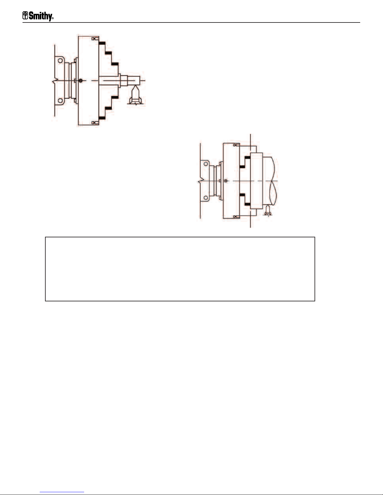
Midas 1220 LTD Operator’s Manual
Figuere 10.18 For short, small-diameter workpieces,
Figure 10.19 For large-diameter workpieces
insert the jaws
with high steps of the jaws to the outside.
insert the jaws with high ends to the center.
Caution
Never leave the chuck key (wrench) in the chuck while the chuck is on the spindle. Any
movement of the spindle can crash the key into the ways, seriously damaging the ways,
spindle, and chuck. Turning on the lathe with the key in the chuck can seriously damage your
lathe. The key can also be thrown when the lathe starts, causing damage and/or injury. Never
let your hand leave the chuck key unless you are picking it up or storing it.
Never remove a chuck or heavy faceplate without first laying a board across the ways to
protect them in case the chuck falls when it comes off the spindle nose. Or use a chuck
cradle to ease chuck removal and installation.
Mounting Work in a Three-jaw Universal Chuck
Work is set up in a three-jaw universal chuck as in a four-jaw independent chuck, with
these ex
• On three-jaw chucks, the key moves all the jaws at once.
• You need not center or check for concentricity because these chucks center
automatical
ceptions:
.
ly
• Jaws are not reversible. Each chuck comes with two sets of jaws. One is for setups with
high steps toward the inside (inside jaws), the other for mounting in the chuck with high
steps to the outside (outside jaws).
10-9
For Assistance: Call Toll Free 1-800-476-4849
Page 48

10: Setting Up with Centers, Collets, and Chucks
• When installing the chuck jaws on a three-jaw chuck, install them in numerical order
and counterclockwise rotation.
Each jaw is stamped with a serial number and jaw number (#1, #2, or #3). The slots in
the chuck are not numbered, but there is a serial number stamped at the #1 slot (Figure
10.20). With the #1 slot in the 12:00 position, the #2 slot is at 8:00 and the #3 slot at
4:00 (Figure 10.21).
To install the jaws, first insert the #1 jaw into the #1 slot and turn the key until it
engages. Then put in the #2 jaw and engage it, then the #3 jaw.
Figure 10.20 A serial number is stamped in the #1 slot of the three-jaw chuck.
Slot #3
Slot #2
Slot #1
Figure 10.21 With the slot for the #1 jaw in the 12:00 position,
the slot for the #2 jaw is at 8:00 and the slot for the #3 jaw is at 4:00.
Collets and Collet Attachments
To hold small-diameter work, whether bar stock fed through the hole in the spindle or
small pieces of semi finished parts, collet attachments are preferable to standard chucks
(Figure 10.22) for several reasons:
• They have much faster release and grip actions.
• They center the work automatical
• They grip even small pieces and pieces with a short hold firmly.
ly and accurately
.smithy.com
isit www
Or V
10-10
Page 49

Midas 1220 LTD Operator’s Manual
Figure 10.22 Collet attachments are best for small-diameter work.
• They are housed within the spindle nose for maximum tool clearance, making it
possible to machine, thread, or cut off close to the spindle.
While chucks are universal tools that hold a range of stock sizes and shapes, collets are
special tools. There is a collet for every size and shape of workpiece.
Made with extreme accuracy, hardened, and ground, standard split collets are slotted so
their jaw ends compress inwardly to grip the workpiece. This is done by pulling the
collet jaw's externally tapered shoulder into a matching taper-bored adapter sleeve. The
adapter sleeve connects the lathe spindles MT5 taper to the collets MT3 taper. A drawbar
holds the col
let in place.
Toolpost Grinders
A fully equipped lathe has a toolpost grinder, a small, independently operated grinding
head with an integral electric motor that mounts as a unit in the toolpost T-slot of the
compound rest. (For lighter work, some are held in the toolpost.) You can maneuver it as
you would any other cutting tool.
Toolpost grinders come wi
different materials and surfaces. They also come with arbors and mounted wheels for
grinding internal surf
aces. You can use them to grind or polish surfaces; to grind lathe
centers, arbors, taper sockets, leader pins, gauges, valve seats, and other close-fitting
parts; and to sharpen tools.
th wheels of different shapes, sizes, and grits for grinding
10-11
For Assistance: Call Toll Free 1-800-476-4849
Page 50

Chapter 11
Lathe Turning
Rough Turning
In turning a shaft to size and shape where you have to cut away a lot of stock, take heavy,
rough cuts to get the work done in the least time. With the MI-1220 LTD use a transverse
powerfeed for heavy cuts-from right to left toward the headstock so the thrust is against
the head-stock or the chuck. Use a right-hand turning or roundnose cutter.
Caution
Remember caution must be taken to not run the powerfeed past their limits of travel.
As part of the normal operation, procedures, run each axis through the entire
length of the proposed machining operation before engaging the powerfeed to
assure there is sufficient travel to accomplish for the desired task. Failure to so could
result in running the power feed to the end of its mechanical limit. This is what is
known as a "CRASH". A crash can cause damage to the work piece and severe
damage to the machine.
After selecting a cutter, place i
be just above or on the line of the centers. The greater the diameter of the work, the
higher the cutter can be. Adjust the height by placing shims under the cutter and raising
or lowering i
th the tool pr
Wi
the right end of the workpiece wi
ard the headstock. Now determine the depth of the cut. Move the tool to the desired
tow
depth ti
Start the lathe. R
the power of the drive or the amount of metal to remove.
Say, for example, you need to reduce a diameter by a known number of thousandths of
an inch. If you zero the collar and watch the movement of the dial, you'll know the depth
of the feed from the zeroing point.
Note: The dial gives a good approximation, but for exact measurements, use a
measuring instrument.
To reduce the diameter, advance the tool only half as many thousandths on the dial. This
is because the tool tak
around the work. F
tool only 0.0025", or 1-1/4 calibrations.
t (Figur
ll it just touches the stock and zero the cross-feed dial.
e 9.1).
operly positioned, tighten the Al
un the cr
es of
or example, to reduce the diameter of a shaft 0.005", you advance the
t into the left side of the turr
len capscrews. Next, run the carriage to
th the hand crank. Make sure the lathe is set to feed
eed in b
ossf
f an equal amount f
y hand to tak
om both sides as i
r
e as heavy a cut as is consistent with
et . The cutter's point should
t cuts a continuous strip
Engage the tool before setting the floating dial. The tool must be moving in the direction
you want to go before you set the dial to zero to compensate for the backlash.
Or V
isit www
.smithy.com
11-1
Page 51

Midas 1220 LTD Operator’s Manual
For a screw to move, there must be some play in the thread. When backing the cutting
tool away from the cut, move the feedscrew enough to take up the backlash before
setting the collar or when drawing the tool from the cut.
Engage the longitudinal feed by moving the powerfeed engagement lever done. Always
cut deeply enough to reach below the scale on oxidized bars or iron castings. Hard,
oxidized surfaces dull tools rapidly.
Finish Turning
After you've rough-turned the workpiece to approximate finished size (within 1/32"),
replace your cutter bit with a freshly ground, keen-edged cutter. Make one or more light
finishing cuts across the machined surface.
Check the diameters carefully with a caliper or micrometer to be sure you are working to
proper dimensions.
Note: The diameter will reduce twice the thickness of the cut.
For rough turning, most machinists prefer a deep cut and a comparatively fine feed, but
the reverse is true for finishing cuts. They usually use a very light crossfeed and a coarse
transverse feed with a cutting edge wider than the feed per revolution. In Figure 11.2,
the left-hand tool illustrates the first roughing cut and the right hand tool shows the
following finishing cut.
Cutting Tool
Figure 11.1 Roughing (left) and finishing (right) cuts.
Turning to Shapes
Other turning cuts, machining shapes, corners, fillets, etc., are done the same way. The
main difference is in selecting cutter bits and maneuvering the cutting point by means of
various cutting tools.
11-2
For Assistance: Call Toll Free 1-800-476-4849
Page 52

11: Lathe Turning
Left Hand
T
Left Hand
Facing
Left Hand
Corner
urning
Parting or
cutting off
Turning with a roundnose cutter
Finishing Cut
Special-form cutter
Right Hand
Turning
Right Hand
Facing
Right Hand
Corner
Figure 11.2 You can do other turning cuts with different cutter bits and cutting tools.
Machining Square Corners
To machine an accurate corner, follow these steps:
1. Set the compound rest perpendicular to the line of the centers and insert a right or
left-hand corner tool.
2. Using the longitudinal feed, turn a small diameter to finish up to the shoulder.
th the compound r
3. Wi
est, feed the tool the amount needed to finish the work to the
length, taking the last facing cut across the shoulder away from the center.
Finishing and Polishing
After machining, you'll want a smooth, polished surface free of machine marks. You'll
e one, use a file.
ou don't ha
obtain the best r
esul
th a toolpost grinder
ts wi
. If y
With a file, take full, biting strokes across the revolving workpiece at a slightly oblique
angle. Do not dr
ag the file back across the work-piece; instead, lift it clear for each return
v
Or V
isit www
.smithy.com
11-3
Page 53

Midas 1220 LTD Operator’s Manual
stroke. Use a clean, dry file and keep the workpiece clean, as well. Wipe the workpiece
dry and clean if you've used coolant or cutting oil. Never hold the file stationary while the
workpiece is revolving.
Figure 11.3 With a file, take full strokes at an oblique angle; never hold the file still.
For an even finer file finish, rub railroad chalk into its teeth. This provides additional
lubrication and absorbs filings. Do not use blackboard chalk.
After filing off the machining marks, polish the workpiece with emery or other abrasive
cloth. Keep the lathe turning at high speed and spread a few drops of oil on the
workpiece. Don't stop moving the cloth.
Figure 11.4 You can polish a workpiece with an abrasive cloth and oil.
Taper Turning
There are two ways to turn a taper: with the compound rest and by setting over the
lstock. I
tai
is to be accurate.
Compound rest. Tapers cut with the compound rest are usually short, abrupt angles, such
as centers, bevel gear blanks, and die parts (Figure 11.5). In general, these are not
consider
Setting over the tailstock. Cutting tapers by setting over the lathe tailstock involves
misaligning the lathe centers. The lathe centers move from their position parallel to the
tool's transverse travel, giving the desired degree of taper (Figure 11.6). The tailstock has
a set-over scale calibrated both forward and backward from the straight turning or
zeroing point f
11-4
n both methods, the cut
ed taper turning, which appl
or measuring set
ter must engage the work on dead center i
ies to machining longer
, mor
-over distances.
For Assistance: Call Toll Free 1-800-476-4849
adual tapers.
e gr
f the taper
Page 54

11: Lathe Turning
To offset the tailstock, loosen the two base-locking bolts (Figure 4.8). To offset to the
right, loosen the right adjusting bolt and tighten the left. To offset to the left, loosen the
left adjusting bolt and tighten the right.
Figure 11.5 Tapers cut with the compound rest are usually short, abrupt angles.
Figure 11.6 In setting over the tailstock, the lathe centers move from their parallel
position with the tool’s traverse travel.
You can turn long, gradual tapers by setting over the tailstock, but take care. Your
computations must be nearly perfect, because an error will spoil your work.
The distance of tai
actors:
f
lstock set o
er needed to machine an
v
en taper depends on thr
y giv
ee
• The differential between the parallel positions with the tool’s traverse travel
• The length of the taper in r
ed
taper
elation to i
ts extr
eme diameters, i
f the entir
e shaft is to be
• The ratio between the length of the tapered portion to the entire length of the shaft (or
work between centers when you're tapering only part of the shaft.
er should equal
When the taper extends the entir
hal
f the di
fference between the finished diameters of the ends (Figure 11.7). When a
e length of the workpiece, tai
lstock seto
taper extends only part of the length of the shaft, divide the total shaft length b
.smithy.com
isit www
Or V
v
y the
11-5
Page 55

Midas 1220 LTD Operator’s Manual
length of the portion to be tapered. Then multiply the resulting quotient by half the
difference between the extreme diameters of the finished taper.
Figure 11.7 Tailstock setover should be half the difference between the finished
diameters of the ends, or 0=T" x L"/2, where T= taper per inch and
L= length of work in inches.
Note: (A) Because most drawings give the taper in inches per foot of length, it may be
easier to convert all dimensions to inches. (B) Be sure to zero the tailstock before
resuming straight turning.
11-6
For Assistance: Call Toll Free 1-800-476-4849
Page 56
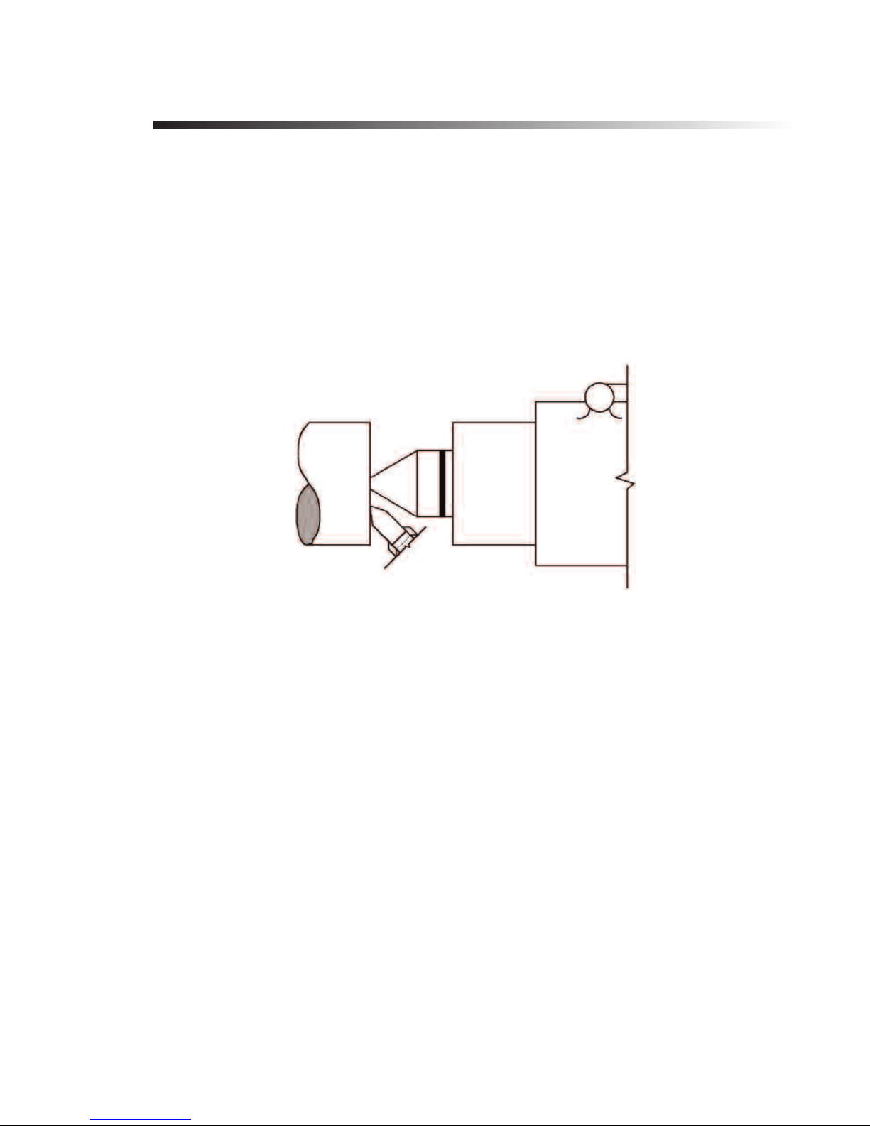
Chapter 12
Lathe Facing and Knurling
Before removing your work from the centers, face or square up the ends. On accurate
work, especially where shoulders, bevels, and the like must be an accurate distance from
the ends, do the facing before turning the shank. This also cleans the ends and machines
the workpiece to accurate length.
When diameters are large, it's best to face with a special side tool that has a long, thin
blade with a wide cutting edge. If you don't have one, use a right or left-hand facing
cutter. Feed the tool from the center outward to avoid marring the lathe center (Figure
12.1).
Figure 12.1 With a facing cutter, feed the tool from the center outward.
Facing Across the Chuck
When facing a stub-end workpiece held in the headstock chuck, the same rules apply.
Chuck the stock, let
straight turning tool with a facing cutter) in the toolpost. Carefully adjust the cutting edge
so it is exactly on center, then tighten it into the toolpost. If you don't do this, a small tit
ojection wi
or pr
run off center.
Start y
center of the workpiece. Do not start with a heavy feed because the sfm increases
rapidly as the cutter moves through increasing peripheries. One or two light cuts is
usually enough to true up an end roughened by the hacksaw. After facing one end,
reverse the workpiece and face the opposite end.
If y
extend the tool across the entire face of the work.
To use the powerfeed for facing, place the speed selector into the desired position before
the lathe is turned on. Once the cutter has been positioned as per the above paragraph,
our lathe on the slowest speed. B
ou must finish the ends of the shaft, use a hal
ting i
ll remain in the center of the stock and perhaps cause the center drill to
ring the tool into cut
-center (Figur
f
otrude about an inch. Place a right
t pr
-hand side tool (or a
ting posi
tion against the
e 12.2). This lets y
ou
Or V
isit www
.smithy.com
12-1
Page 57

Midas 1220 LTD Operator’s Manual
move the crossfeed lever down. Pull the lever up at the end of the cut to stop the cutter
travel.
Caution
Remember caution must be taken to not run the powerfeed past their limits of travel.
As part of the normal operation, procedures, run each axis through the entire
length of the proposed machining operation before engaging the powerfeed to
assure there is sufficient travel to accomplish for the desired task. Failure to so could
result in running the power feed to the end of its mechanical limit. This is what is
known as a "CRASH". A crash can cause damage to the work piece and severe
damage to the machine.
Figure 12.2 With a half-center you can extend the tool across the entire face of the work.
Knurling
Strictly speaking, knurling is not a machining operation because no metal is cut. It is a
orming oper
f
raising the surface of the metal into a pattern. As with all other forming operations, your
work can be no better than the pattern, your knurling no better than the knurls. Be sure
the knurls ar
To make a true, uniform knurl, maintain uniform pressure on both knurls. Select a
self-centering knurling tool that equalizes pressure on the knurls automatically and is
strong enough to withstand end and side thrusts. Operate the lathe at the slowest speed
(160 rpm).
Knurling exerts extreme thrust against centers and bearings. You can lessen this thrust
materially by feeding the knurling tool at a slight angle off from perpendicular to the line
of the workpiece. This engages the right side of the knurl first (Figure 12.3).
Place a few dr
knurling tool f
depth of 1/64". Then stop the lathe and inspect the work. If the knurl is not clear-cut,
adjust the tool in or out as needed.
ation in which pat
e sharp
rom the right-hand scribe line and feed them in until the knurl reaches a
, clean-cut (pr
ops of oi
terned knurls are pressed into the work, depressing and
ably hob-cut), and properly hardened.
er
ef
l on the workpiece and knurling tool. Start the rolls of the
12-2
For Assistance: Call Toll Free 1-800-476-4849
Page 58

12: Lathe Facing and Knurling
Use plenty of oil, lubricating both knurl and workpiece. Then start the lathe and engage
the automatic feed, moving the knurls across the portion to be knurled. When you reach
the left scribe line, force the tool into the work another 1/64", reverse the lathe without
removing the tool, and feed it back to the starting point. Feed both ways using the
automatic longitudinal feed. Once across, each way, usually makes a good knurl.
Figure 12.3 Feed the knurling tool at a slight angle off from perpendicular to the
line of the work piece.
Or V
isit www
.smithy.com
12-3
Page 59

Chapter 13
Cutting off or Parting with a Lathe
You can cut off in a lathe only when holding one end of the work rigidly, as in a chuck.
It is not practical for long workpieces held between centers because the workpiece is not
supported closely with a rest and the free section is long enough to sag and pinch the
blade. Cutting off requires a tight lathe without excess play in the spindle, compound,
carriage, or toolpost. Looseness will almost certainly cause chatter. Cutting off also
requires a narrow cutting edge with ample (5-10°) side clearance, which should feed into
the work slowly to prevent hogging in. Once considered a difficult, costly operation,
cutting off became much simpler with development of narrow tools with special cutoff
blades (Figure 13.1).
The toolpost should hold the cut-off tool as close to the workpiece as possible, with the
top of the blade on dead center and exactly perpendicular to the line of centers. Extend
the blade only far enough to pass through the work-piece, just beyond its center. The tool
should f
the tool hogs in and the spindle stops rotating, turn off the motor and reverse the
spindle by hand before backing the tool out with the crossfeed.
eed to the workpiece on exact center
, slowly and evenly with the cross-feed. If
Figure 13.1 Specially designed tools like this one make cutting off easier.
Always set up the workpiece to cut off as close as possible to the headstock. If you must
make a parting cut on a long shaft or on work between centers, don't complete the cut
in the lathe. Finish the parting wi
the spindle speed until you have a good feel for cutting off. Although lubricants and
coolants are not essential on small-diameter workpieces, use them amply on deep cut-off
work.
13-1
th a hacksaw and return it to the lathe for facing. Slow
For Assistance: Call Toll Free 1-800-476-4849
Page 60

Chapter 14
Lathe Drilling and Boring
You can lathe drill on the MI-1220 LTD in two ways, holding the drill stationary and
revolving the workpiece, or holding the workpiece stationary and revolving the drill.
Holding the drill stationary in a tailstock chuck gives a straighter hole (Figure 14.1).
Without changing setup and re-centering, the work is ready for any succeeding
operations, such as boring and internal threading. In all lathe drilling operations, keep the
drill sharp and properly ground. This is essential for obtaining a straight, accurate hole.
Figure 14.1 Holding the drill stationary in the tailstock chuck gives a straighter hole.
With HSS drills, operating speeds are not as critical as with carbon-steel drills High speeds
can quickly "burn" a carbon-steel dri
drills even more than to other cutting edges because there is practically no air cooling of
the point after i
peripheral f
no drilling speed data are available, it's generally safe to run drills under 1/4" diameter at
up to 750 rpm and drills up to 1/2" diameter at 500 rpm, with larger drills at
proportionately slower speeds.
With the workpiece in the headstock and the drill in the tailstock chuck, feed the drill into
the workpiece b
Make a locating center for the drill point, or even a countersunk center for large
diameters, to k
t enters the hole. The larger the dri
eet cut per revolution. That is why you should use a slower drilling speed. If
y advancing the tailstock ram. Do this by turning the tailstock handwheel.
om cr
r
l f
eep the dri
l
ll. The number
eeping.
-of-feet-per-minute rule applies to
ll, the greater the number of
Reaming
When a hole must be accurate to 0.002" or less, drill it slightly undersized (0.010" to
1/64" on smal
it either by hand or in the lathe. Lathe reaming is usually done with solid reamers held in
lstock chuck or wi
a tai
center. Use slow speeds and feed the reamer slowly and evenly into the workpiece. Be
sure the reamer teeth are free of burrs and chips.
l diameters and 1/64" to 1/32" on holes 1" to 2" in diameter). Then r
th a taper shank that fi
ts the tai
lstock r
am in place of the tai
eam
lstock
Or V
isit www
.smithy.com
14-1
Page 61
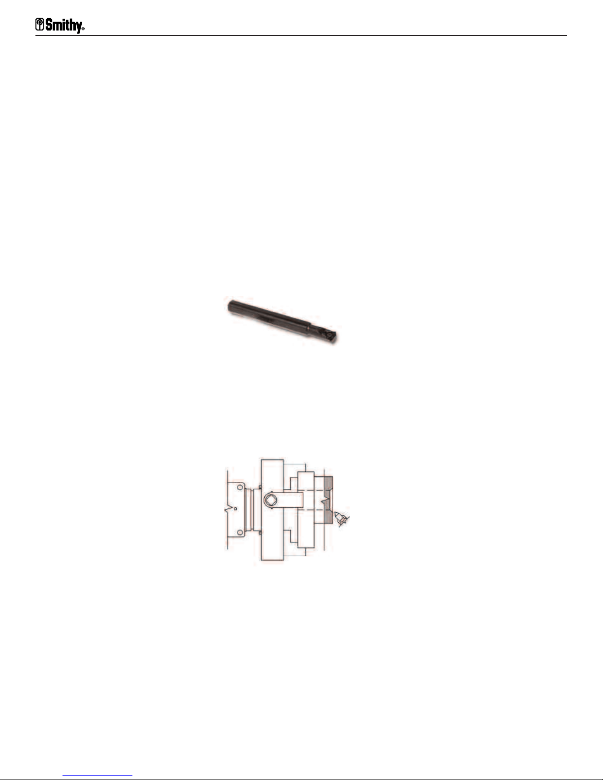
Midas 1220 LTD Operator’s Manual
Boring
Boring is internal turning, or turning from within. The diameter of the opening to be bored
is often much smaller than its depth. Boring tools must therefore have relatively small
diameters and still support a cutting edge projected at considerable distance from the
toolpost or compound rest.
Boring tools consist of an extremely stiff, strong bar with a formed cutting end or a way
to hold an HSS cutter or carbide insert. There are many sizes and types of boring bars.
Choose the one that will give the stiffest possible bar at every depth and diameter and
the greatest choice of cutters and cutter angles (ask a Smithy technician about the Smithy
boring head combo package, Item# K99-125).
It is also wise to select tools with smooth-ended bars without a projecting nut or
hardened edge that might mar the work (Figure 14.2). Most boring tools have only one
cutting edge. There are double-end cutters, however, and they offer advantages in
special instances. In grinding cutters, allow sufficient end rake to provide clearance from
the internal diameter.
Figure14.2 A tool with a smooth-ended bar won't mark the workpiece.
cept wi
Ex
th cored castings, pipes, or tubing, begin by drilling a hole large enough to
admit the end of the boring bar. Because the holes in cored castings often deflect boring
bars from their true axis, you may want to chamfer or turn out a starting cut in the opening of the hole to be bored with a turning tool before introducing the
boring tool.
Figure 14.3 Chamfer a starting cut in the opening of the hole.
With the boring toolholder set up (in the toolpost or toolpost T-slot, depending on the
type), select the largest-diameter boring bar whose cutter the bore will accept. Extend
l allow
the bar f
tool clear
om the holder just enough to r
r
ance. Ex
cept when using the adjustable boring tool (usual
each the f
l depth to be machined and sti
ul
ly for very-large-
l
diameter work), feed the bar into the hole, parallel to the holes axis. The cutting edge
engages the work along a line in the mounted plane of the lathe centers with the bar
positioned to give the cutter a top rake of approximately 14° from the radius at the
cutting point (Figure 14.4). This takes into consideration the ground angle (top rake) of
.
f
the cutter i
tsel
14-2
For Assistance: Call Toll Free 1-800-476-4849
Page 62

14: Lathe Drilling and Boring
Figure 14.4 The cutting edge engages the work piece along a line
in the mounted plane of the lathe centers
For straight longitudinal cuts, you can hold the cutter close up, therefore more rigidly, if
it's at a 90° angle to the bar. For machining ends of a bar, however, you need a boring
bar that holds the cutter at an angle or angles so the cutter extends beyond the end of
the bar (Figure 14.5). For maximum visibility, position the cutting edge at the near side,
parallel to the centerline.
cept-as noted earlier
The rules that apply to external turning apply to boring as wel
l, ex
where the rake angles differ. The rake angles are governed by cutter type and bore diameter. Feeds must be lighter to keep the tool from springing. This is especially true when
enlarging out-of-round holes, when you take several small cuts rather than one heavy cut.
Figure 14.5 To machine ends of a bar, use a boring bar that angles
the cutter so it extends beyond the bar
After the last finish cut, it is common to reverse the feed and take one last, fine cut with
the tool coming out of the work. This last cut, taken without movement of the cross-feed,
avoids a slightly undersized hole because you compensate for any spring in the bar.
Cutting Internal Threads
Internal thread cutting is like external thread cutting, except you have the clearance
restrictions and tool problems of boring. You use the same toolholders, but the cutters
have thread forms and are fed at thread-cutting ratios of feed to spindle revolutions.
ence between boring and inside threading is the cutting angle at which the
er
f
Another di
f
Or V
isit www
.smithy.com
14-3
Page 63
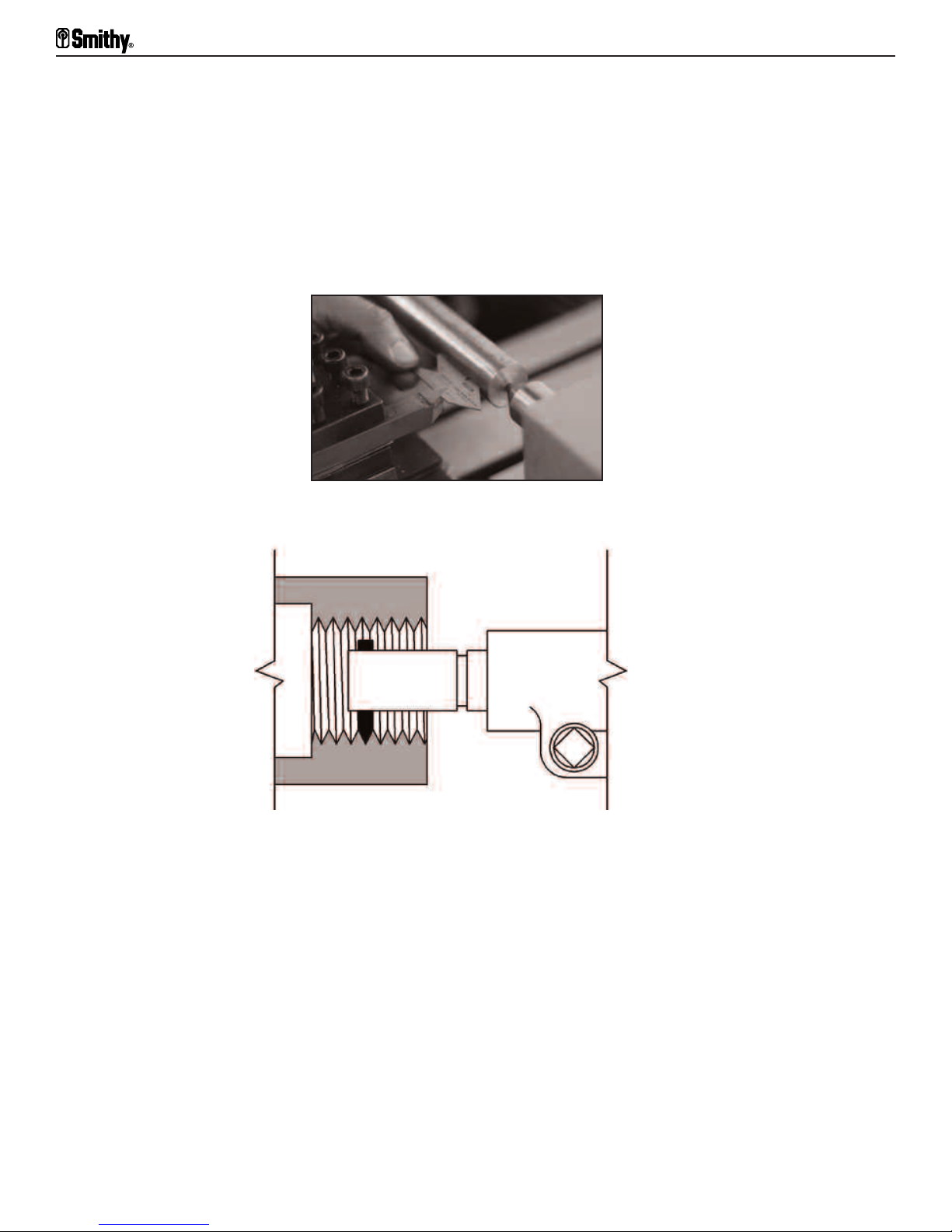
Midas 1220 LTD Operator’s Manual
cutter approaches the workpiece. As with external thread cutting, the internal threading
tool must engage the work on dead center and be held so the cutter coincides with the
workpiece's center radius.
In squaring the cutter with the work, use a center gauge (Figure 14.6) or thread gauge.
Internal cutters require greater end and side clearance, and cutter length is also restricted because internal thread cutters must have enough end clearance that for different
thread types. the cutter lifts clear of the thread for removal (Figure 14.7). Before cutting
an internal thread, bore the workpiece to the exact inside diameter.
Figure 14.6 Use a center or thread gauge to correct cutter alignment error
when squaring the cutter with the workpiece.
Figure 14.7 There must be enough end clearance for the cutter to lift clear of the thread.
d, not away from, the operator, the
ecause the f
B
ead-cut
thr
ting set is reversed. Also, you must take lighter cuts because of the cutter's
eed of suc
e cuts is tow
cessiv
ar
extension from the toolpost. Take an extra finishing cut without changing the setting of
the compound rest.
Cutting Special Form Internal Threads
You can cut internal forms in all the thread forms used for external threads. There is only
one factor that calls for special attention in cutting special-shaped internal threads: the
difference of clearances between the nut and screw recommended for different thread
types (Figure 14.8). If you don't have recommended clearances, it is safe to cut a nut
thread (internal thread) 0.005" to 0.010" per inch larger in the screws outside diameter.
14-4
For Assistance: Call Toll Free 1-800-476-4849
Page 64

14: Lathe Drilling and Boring
Figure 14.8 Use different clearances between nut and screw for different thread types.
Or V
isit www
.smithy.com
14-5
Page 65

Chapter 15
Changing Gears on Your MI-1220 LTD
To change gears on the MI-1220 LTD follow these steps.
Tools required:
10-mm wrench
6-mm Allen wrench
Screwdriver (to remove C clips)
Pliers (to replace C clips)
1. Remove all C clips, nuts, and gears, starting with the A gear and ending with the D
gear. With the 10-mm wrench, loosen the B and C gear shaft in its bracket by turning the
gear shaft counterclockwise (Figure 13.1). This allows the shaft to slide freely along the
bracket for easy gear removal and replacement.
Figure 15.1 Remove all C clips, nuts, and gears
2. Select the proper A-D gear combination from the list outside the pulley box door.
3. Use the Allen wrench to loosen the bolt at the bottom of the bracket assembly for full
swing and easy gear replacement (Figure 13.1).
4. Place the selected D gear on the D shaft, flange side in. Replace the spacer, washer,
and nut.
5. Place the selected C gear, flange side in, on the B and C gear shaft.
6. Place the selected B gear, flange side in, on the B and C gear shaft. Replace the C clip.
7. Slide the B and C gear shaft until the C gear meshes properly with the D gear and
tighten it with the 10-mm wrench (Figure 13.2).
15-1
For Assistance: Call Toll Free 1-800-476-4849
Page 66

15: Changing Gears on your MI-1220 LTD
Figure 15.2 Slide the B and C gear shaft until the C gear meshes with the D gear
8. Place the selected A gear, flange side in, on the A gear shaft and replace the C clip.
9. Swing the bracket assembly until the A and B gears mesh. Hold the bracket assembly
in place and tighten the bolt. Make sure the gears turn smoothly before engaging the
powerfeed. You may need to make some adjustments.
10. Engage the E gear between the C and D gears to reverse the leadscrew.
Figure 15.3 Engage the E gear between the C and D gears to reverse the leadscrew.
Or V
isit www
.smithy.com
15-2
Page 67

Chapter 16
Cutting Threads on Your MI-1220 LTD
Threading Terms
Before beginning to cut threads, it's useful to learn the major terms used in thread
cutting:
•
Pitch. Metric pitch is the distance from the center of a thread to the center of the next
thread. To measure pitch in inches, measure an inch on a bolt and count the threads.
•
Pitch Diameter. This is the diameter of an imaginary cylinder superimposed on a
straight screw thread, the surface of which would make an equal width of the thread and
the spaces cut by the cylinder.
• Lead. The lead is the distance a screw thread advances axially (as through a nut) with
one complete revolution. The lead and pitch of a single thread are identical, but they
differ on multiple threads (the lead of a double thread is twice its pitch; of a triple thread,
three times its pitch).
Because screw-thread cutting is so generally a part of machine work, anyone interested
in building things of metal should master it. Threading requires patience and skill. Before
attempting to cut a thread on a workpiece, cut a f
iron, and aluminum.
Built for thread cutting, the MI-1220 LTD cuts standard internal and external threads, as
l as special thr
wel
per inch, in V or squar
metric. You can cut single threads or multiple threads that run concurrently along the
shaft. You determine the type of thread by how you'll use the screw. Each thread form
es a di
equir
r
For most work, beginners use the Unified National Standard, which is a V-form thread
slightly flat on top and at the root. Pitch numbers, such as 18 or 24, usually refers to
screw threads meaning 18 or 24 threads per inch (TPI).
ead charts on the inside of the door of y
Thr
metric measurements. The inch chart shows the TPI from 6 to 120. The metric shows the
distance from thread crest to crest from 0.50 to 4 mm.
For right-hand threads, start the threading or chasing tool at the right end of the
workpiece and f
leadscrew's r
eads. Y
erent-shaped tool to cut or chase it.
f
f
eed i
otation direction and feed the threading tool from left to right.
ou ma
e shapes, in established profiles like Unified National, acme, and
t tow
y cut coarse or fine threads in a gr
d the headstock. For left-hand threads, reverse the
ar
ew practice threads on odd bi
eat r
our machine and shows both inch and
ts of steel,
ange of thr
eads
With practice, you can grind cutters to almost any profile. It is difficult, however, to
sharpen such cutters without altering the cutting form, and almost every resharpening
requires a complete r
egrinding of pr
16-1
le and clearance angles.
ofi
For Assistance: Call Toll Free 1-800-476-4849
Page 68

16: Cutting Threads on your MI-1220 LTD
After turning the work to be threaded to the outside diameter of the thread and setting
the gears for the desired thread, put a threading tool in the toolpost.
Set it exactly on the dead center of the workpiece you'll be threading.
To make sure your cutter is on dead center, place a credit card or shim between the
cutter point and workpiece (Figure 16.1). When the tool is on dead center, the credit card
or shim will remain vertical. With a credit card, there is no possibility of chipping the
cutter as the workpiece and cutter come together.
Figure 16.1 Check dead center with a credit card.
Set the compound perpendicular to the line of centers and rotate it 29-1/2° to the right .
Figure 16.2 With the compound perpendicular to the line of centers,
rotate it 29.5 degrees to the right.
Place the thread gauge on the point of the threading tool and feed the tool toward the
work-piece (Figure 16.3). Adjust the tool so the edge of the gauge is exactly parallel to
the workpiece. A sl
ip of white paper held below the gauge will help check the parallel of
the gauge to the shaft and the fit of the toolpoint in the V of the gauge. Placing the
threading tool perpendicular to the surface of the workpiece assures a true-form thread.
Or V
isit www
.smithy.com
16-2
Page 69
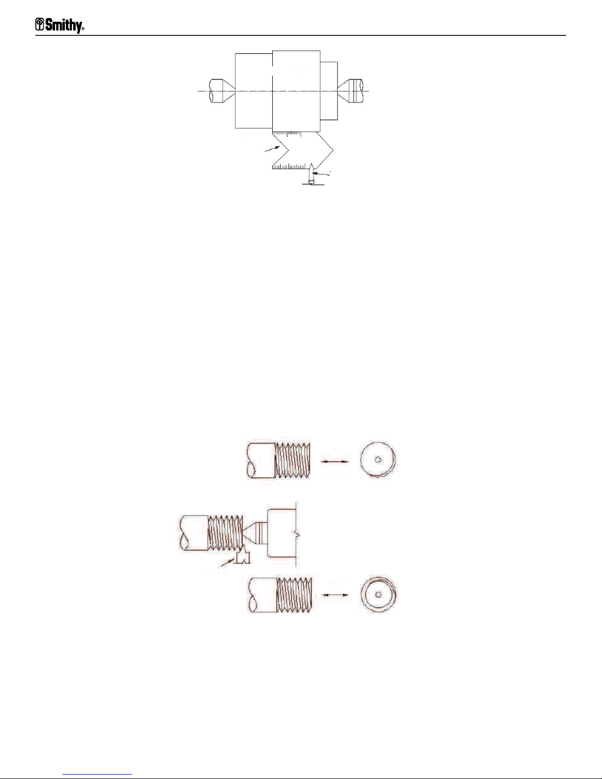
Midas 1220 LTD Operator’s Manual
Workpiece
Center
Gauge
Toolbit
Figure 16.3 Using a center gauge, set the threading tool perpendicular to the work piece.
Cutting Right-hand Threads
Place the leadscrew selector in position to feed the cutter from right to left, toward the
headstock. Now you are ready to cut right-hand threads. First, advance the tool so it just
touches the workpiece and turn the compound calibration back to zero. Then, using the
compound feed, feed in the tool 0.002". Next, turn on the lathe and engage the halfnut
lever carefully pushing the handle down. Do not force it, and do not disengage it until you
are completely done.
It is best to take a light, scratch cut first without using cutting fluid. After the tool runs
the desired length, turn off the lathe and back the tool out of the work. Then reverse the
motor to return the tool to the starting position. Using a screw-pitch gauge, check the
thread pitch. The benefit of taking the light cut is that you can correct any mistakes you
might have made.
Before
Tool
After
Figure 16.4 Chamfer the end of the thread to protect it from damage.
It's time to take the real cut now, so apply the appropriate cutting fluid to the work. Feed
the compound feed in 0.005-0.020" for the first run, depending on the pitch of the thread
you have to cut. If you are cutting a coarse thread, start by taking a few heavy cuts.
Reduce the cut depth f
or each run unti
feed calibration, then make the second cut.
16-3
l it is about 0.002" at the final run. Zero the cross-
For Assistance: Call Toll Free 1-800-476-4849
Page 70

16: Cutting Threads on your MI-1220 LTD
Single Thread
ouble Thread
D
Triple Thread
Figure 16.5 When cutting multiple threads, increase the lead to
make room for succeeding threads.
Continue this process until the tool is within 0.010" of the finished depth. Brush the
threads regularly to remove chips. After the second cut, check the thread fit using a ring
gauge, a standard nut or mating part, or a screw thread micrometer. It is best to leave
the piece in the chuck and not remove it for testing.
eturning the workpiece to the setup
After r
, continue taking 0.001-0.002" cuts. Then check
the fit between each cut. When you thread the nut, it should go on easily but without end
play. When you have the desired fit, chamfer the end of the thread to protect it from
damage. To chamfer is to take a 45° cut off the end of the bolt.
Using the Threading Dial
The threading dial performs the function of
indicating the proper time to engage the
f-nut so that the cutting tool will enter the
hal
same groove of the thread of each successive
ting pass. This allows the half-nut to be
cut
disengaged resulting in an easier method of
threading. At the end for each consecutive pass
the half-nut can be disengaged and the carriage
Figure 16.6 Threading dial
thout stopping the spindle or r
wi
way from the workpiece and move the cutter back to the beginning of the thread
ter a
cut
with the hand wheel. Turn the cutter the desired amount and you are ready for the next
threading pass. The threading dial is marked with lines numbered 1,2,3,4,5 and 6 and a
single reference line on the housing of the dial. The indicator table shows the selection
for the different thread pitches. Find the desired thread pitch under the "TPI" column and
-nut at the pr
engage the hal
f
"1-6" means the hal
f-nut can be engaged on any of the numbered lines 1 through 6. "1,4"
oper numbers shown on the "SCALE" column of the table.
means that the half nut can be engage on 1 or 4 only. "1" indicates that the half-nut can
be engaged on 1 only. For any thread pitch not listed on the chart, cut a test thread and
engage the half nut on 1 or 4 only. If the test cut is not successful, the thread dial annot
om the pr
be used and the instructions f
metric thr
eads cannot be done wi
r
th the thread dial.
can be moved back to the start of the thread
ersing the motor
ev
. Disengage the hal
f-nut, back the
evious section should be followed. Cutting of
Or V
isit www
.smithy.com
16-4
Page 71

Midas 1220 LTD Operator’s Manual
TPI SCALE TPI SCALE TPI SCALE TPI SCALE TPI SCALE
6 1,4 10 1-6 14 1,4 22 1,4 30 1-6
7 1 11 1 16 1,4 24 1,4
8 1,4 12 1,4 18 1-6 26 1,4
9 1-6 13 1 20 1-6 28 1,4
Table 16.1 Indicator Scale
Cutting Multiple Threads
Cut multiple threads one at a time exactly as you cut single threads, except increase the
lead to make room for succeeding threads (a double lead for a double thread, a triple lead
for a triple thread, etc.). After completing the first thread, remove the work from the
centers without loosening the lathe dog. Then put it back in the lathe with the tail of the
lathe dog in the correct slot to index the work for the next thread. This work requires a
faceplate wi
number of threads to be cut.
th accurately posi
tioned slots, uniformly spaced and equal in number to the
What Not To Do When Cutting Threads
Do not disengage the powerfeed direction lever. Do not shift the powerfeed speed lever.
ve the lathe dog until the thread is finished
e cutting between centers, don't r
ou ar
If y
and tested, and don't disturb the spindle whi
When y
necessary, remove the workpiece from the center, leaving the lathe dog attached, then
test the thread. If it does not fit properly and you have to remove another chip or two,
place the woprkpiece back in the centers exactly as it had been, then remove the chips
and test again. Repeat until finished.
ou think the thr
ead is finished and ready for testing, and only if absolutely
emo
le the work is off the centers.
Finishing Off a Threaded End
After cutting a thread and before removing the threading tool, chamfer the end. This
improves its appearance and removes sharp corners and burrs. It also aids the screw as
t engages a nut or threaded hole.
i
Cutting Threads on a Taper
Cut threads on a taper the same as on a straight shaft, except in the setup of the tool.
Set the threading tool at 90° to the axis of the taper, rather than at 90° to its surface
(Figure 16.7).
16-5
For Assistance: Call Toll Free 1-800-476-4849
Page 72

16: Cutting Threads on your MI-1220 LTD
Wrong
Right
Figure 16.7 When cutting a thread on a taper, set the threading tool at (missing text)
MM
INCH THREADS
I 0 II I 0 II
30 15
28 14
A X C
B D
27 X 27
70 60
70 X 40
32 45
70 X 40
32 42
INCH THREADS
I 0 II I 0 II
32 16
36* 18*
A X C
B D
27 X 27
70 60
70 X 40
32 48
70 X 40
32 54
INCH THREADS
I 0 II I 0 II
0.50 1.00
0.60 1.20
A X C
B D
49 X 42
32 56
49 X 42
32 56
49 X 45
32 50
26 13
A
B
24 12
70 X 40
32 39
70 X 40
32 36
40* 20*
48* 24*
70 X 32
32 48
70 X 30
36 48
0.70
1.25
45 X 49
48 32
49 X 42
32 40
C
D
22 11
20 10
18 9
70 X 40
32 33
70 X 40
32 30
70 X 45
27 36
56* 28*
60* 30*
64* 32*
42 X 50
36 56
70 X 30
48 54
70 X 30
48 60
0.75 1.50
0.80
1.75
63 X 42
32 48
49 X 60
50 32
49 X 63
48 32
A
16 8
70 X 45
27 32
80* 40*
70 X 30
48 60
1.00 2.00
63 X 49
32 42
B
C
14 7
60 X 60
27 32
96** 48**
39 X 45
60 48
1.25 2.50
60 X 49
32 32
E
D
12 6
70 X 60
27 32
120 60
42 X 30
54 48
1.50 3.00
63 X 56
32 32
333 167
30 X 27
60 63
Table 16.2 Threading Chart for the MI-1220 LTD
.smithy.com
isit www
Or V
2.00 4.00
70 X 63
30 32
16-6
Page 73

Midas 1220 LTD Operator’s Manual
A
I 0 II I 0 II I 0 II I 0 II
A X C
B D
B
27 X 27
70 60
0.0011 0.0022 0.001 0.0003
C
70 X 40
32 45
0.0126 0.0252 0.0015 0.0030
D
70 X 40
32 42
70 X 40
32 39
70 X 40
32 36
A
B
C
E
D
70 X 40
32 33
70 X 40
32 30
70 X 45
27 36
70 X 45
27 32
60 X 60
27 32
0.0135 0.0270 0.0016 0.0032
0.0145 0.0290 0.0017 0.0034
0.0157 0.0314 0.0018 0.0037
0.0171 0.0343 0.0020 0.0041
0.0189 0.0377 0.0022 0.0044
0.0210 0.0149 0.0025 0.0049
0.0236 0.0471 0.0028 0.0055
0.0269 0.0529 0.0032 0.0063
Table 16.3 Feed Rates for the MI-1220 LTD
16-7
70 X 60
27 32
For Assistance: Call Toll Free 1-800-476-4849
0.0314 0.0628 0.0037 0.0074
Page 74

Chapter 17
Milling
In milling, one or more rotating cutters shape a workpiece held by a vise or other
holding device. The cutters mount on arbors or at the end of the spindle in collets or
adapters.
Millhead
(Rotates 180 degrees)
Main Lock
(At the back)
Centering Lock
Figure 17.1 MI-1220 LTD Milling/Drilling parts
Machinists use mills to machine flat surfaces, both horizontal and vertical, and to make
shoulders, grooves, fillets, keyways, T-slots, and dovetails. They can also make curved
y of machining operations
ate holes. Its v
and irr
and high metal-removal rates rank the mill in importance with the lathe.
The mi
of the head carries the spindle.
Y
long-feed handwheels The cross-slide handwheel turns the table longitudinally (at right
angles to the spindle axis); the long-feed hand crank moves it transversely (parallel to the
spindle axis).
To rotate the mill head, loosen the centering lock on the front of the mill head and the
mai
egular surf
llhead rotates 180 degrees and adjusts up and down. A quill that moves in and out
ou can mo
l lock on the back.
aces and machine ac
e the table horiz
v
ontal
cur
ly in two dir
ections by turning the cross-slide and
ariet
Crank Shaft
Or V
isit www
.smithy.com
17-1
Page 75

Midas 1220 LTD Operator’s Manual
Push the mil head in the desired direction. Lock the main and centering locks to hold the
head into position
To recenter the mill head, push the head into the approximate centered position. Move
the head back and fourth slightly while tightening the centering lock. The head will work
its way into the centered position.
The mill head may be raised to accomodate larger work pieces. Unlock both locks and
slide the crank handle over the square ended shaft on the front of the mill head. Crank
to the desired height and lock into position.
Holding Milling Cutters
There are several ways to hold milling cutters - in arbors, with collets and special
holders, and in adapters.
Drawbar
Arbor attaches to the
drawbar inside the
drawbar
Figure 17.2 MI-1220 LTD milling attachments
Arbors
Arbors come in different sizes and lengths, with one end tapered to fit the bore in the
end of the machine spindle. The arbor of theCB1220 XL LTD, which has an MT3 taper, is
driven by the friction between the arbor and spindle. The arbor stays in place by means
wbar scr
of a dr
T
f
a
ake good care of your arbors. Store them in a rack or bin. If you won't be using them
or sev
eral days or longer, oil them to prevent rusting, especially in damp weather.
ewed into the end of the arbor from the top of the spindle.
Collets and Holders
Straight-shank end mills fit into spring collets or end mill holders. Their precision-ground
shanks go into the mi
and the collet grips the end mill shank evenly. Tighten the end mill securely with the
setscrew against the flat surf
workpiece, the cutter, or you.
ll spindle. When you tighten a spring collet, its hole reduces in size
ip out and damage the
y sl
t ma
l, or i
ace of the end mi
l
17-2
For Assistance: Call Toll Free 1-800-476-4849
Page 76

Figure 17.3 Spring collets, which fit into the mill spindle, hold straight-shanked end mills.
Adapters
Adapters mount various types and sizes of cutters on the spindle. Arbor adapters mount
face mills on the spindle. Collet adapters mount end mills on the spindle. Taper-shank end
mills mount in adapters that have holes with matching tapers. If the taper shank on the
tool is smaller than the hole in the adapter, put a reducing sleeve into the adapter. Shell
end mill adapters come in different sizes to accept different sized shell end mills.
17: Milling
To remove arbors or adapters held with a drawbar, follow these steps:
1. Loosen the locknut on the dr
awbar about two turns.
2. Hit the end of the drawbar with a dead blow hammer, releasing the arbor or adapter
from the spindle hole.
3. Hold the arbor or adapter so it won't fall out of the spindle when the drawbar is
removed.
4. Unscrew the drawbar and remove the arbor or adapter.
Figure 17.4 End mill holders also receive straight-shanked end mills.
low these steps:
our machine includes a taper
Y
ed dri
ft f
or r
ving tapers. F
emo
ol
1. Remove the drawbar.
2. Extend the mill spindle to expose the outer taper drift slot.
otate the spindle to al
3. R
end of the adapter through both slots.
4. Insert the drift in the slot.
ign outer and inner taper dri
.smithy.com
isit www
Or V
ft slots. Y
ll be able to see the
ou wi
17-3
Page 77

Midas 1220 LTD Operator’s Manual
5. Holding the adapter with one hand, use a non-marring hammer (rubber, dead-blow, or
brass) to drive the drift into the slot. The taper on the tool will release and the adapter
drop out.
Cutters mounted in the spindle must fit accurately. There are two ways to make sure they
do. For small cutters, fit the shank of the arbor that carries the cutter directly into the
taper hole at the end of the spindle. A drawbar holds the arbor in place. For large
cutters, bolt the cutter directly to the end of the spindle.
Miling Cutters
Choose milling cutters for the type of cut, the number of parts, and the material. Rake
angles depend on both cutter and work material. Clearance angles range from 3° to 6°
for hard or tough materials to 6° to 12° for soft materials.
To determine the number of teeth you want, consider the following:
• There should not be so many teeth that they reduce the free flow of chips.
• The chip space should be smooth so chips don't clog.
• Don't engage more than two teeth at a time in the cut.
End Mill Cutters
End mill cutters cut on their ends and sides. They are either solid (cut from a single piece
of material) or shell (separate cutter body and shank). They have two, three, four, or
more teeth and may do right or left-handed cutting. Their flute twist or helix may also be
right or left-handed. Solid end mills have straight or tapered shanks; shell end mill
adapters have tapered shanks.
End mills machine horizontal, vertical, angular, or irregular surfaces in making slots,
keyways, pockets, shoulders, and flat surfaces.
• Two flute, or center-cutting end mills have two teeth that cut to the center of the mill.
They may feed into the work like a drill (called plunge milling), then go lengthwise to form
a slot. Teeth may be on one end (single-ended) or both ends (double-ended).
Figure 17.5 Two-flute end mills have two teeth that cut the center of the mill
• Multiple flute end mills have three, four, six, or eight flutes and may be single or
double-ended. Multiple-flute mills are center cutting or non-center cutting. Don't use
non-center cutting end mills for plunge milling.
17-4
For Assistance: Call Toll Free 1-800-476-4849
Page 78

• Geometry forming end mills form particular geometries. They include ball end mills,
roughing end mills, dovetail end mills, T-slot cutters, key seat cutters, and shell end mills.
• Ball end mills (Figure 17.6) cut slots or fillets with a radius bottom, round out pockets
and bottoms of holes, and do die sinking and die making. Four-fluted ball end mills with
center cutting lips are available.
Figure 17.6 Ball end mills cut slots or fillets with a radius bottom
17: Milling
• Roughing end mills remove large amounts of metal rapidly with minimum horsepower.
They ha
ve three to eight flutes. Also called hogging end mills, they have wavy teeth on
their periphery that pro-vide many cutting edges, minimizing chatter.
•
T-slot cutters cut T-slots. After machining a groove for the narrow part of the T-slot with
an end or side mill, finish up with the T-slot cutter.
• Keyseat cutters cut keyseats for Woodruff keys (shaped like a half circle).
• Shell end mills which mill wide, flat surfaces, have a hole for mounting on a short arbor.
The center of the shell is recessed to provide space fro screw or nut that fastens the
ter to the arbor. The teeth ar
cut
e usual
ly helical, and diameters ar
e as large as 6”.
Figure 17.7 Shell end mills mill wide, flat surfaces and mount on arbors
• Insert-type end mills use replaceable HSS or carbide inserts. Small end mills use two
inserts; lar
Face milling cutters start in size at 2" and have inserted teeth the periphery and face.
•
Most of the cut
ger end mills, three or more.
ting tak
end mills.
es place on the periphery
.smithy.com
isit www
Or V
. They ar
e simi
, but larger than, shell
lar to
17-5
Page 79

Midas 1220 LTD Operator’s Manual
Plain Milling Cutters
Plain milling cutters have teeth only on their periphery. Used to mill plain, flat surfaces,
they may combine with other cutters to produce various shapes. They are cylindrical and
come in many widths and diameters.
• Light-duty plain cutters for light cuts and fine feeds come in two forms. Narrow ones
have straight teeth parallel to the cutter axis. Wide ones have helical teeth at a 25° angle.
Features include ease of starting cuts, little chatter, and good surface finishes.
• Heavy-duty plain cutters, or coarse-tooth cutters come in larger widths and have larger and fewer teeth. Strongly supported cutting edges and wide flutes provide strength
and space for heavy chip removal. The helix angle of their teeth is 25° to 45°.
• Helical plain milling cutters have even fewer and coarser teeth with a helix angle of
45-60° or greater. These cutters are for wide, shallow profiling cuts on brass or soft steel.
Side Milling Cutters
Similar to plain milling cutters, side milling cutters also have teeth on one or both sides.
The teeth on the periphery do most of the cutting; those on the sides finish the side of
the cut to size. They cut grooves or slots and often work with other cutters to mill
special shapes in one operation.
Figure 17.8 Side milling cutters are similar
to plain milling cutter, but they have
teeth on one or both sides
• Plain side milling cutters have straight teeth on the periphery and both sides. Side
teeth taper toward the center of the cutter, giving side relief or clearance.
• Half side milling cutters have helical teeth on the periphery and one side. These
cutters do heavy-duty face milling and straddle milling where teeth are needed on only
one side. The side teeth are deeper and longer for more chip clearance.
• Staggered-tooth side milling cutters are narrow cutters with teeth alternating on
opposite sides. There is less dragging and scoring and more space for chip removal.
These cutters do heavy-duty operations.
Slitting Saws
Slitting saws do narrow slotting and cut-off operations.
17-6
For Assistance: Call Toll Free 1-800-476-4849
Page 80

• Plain slitting saws are thin, plain milling cutters with only peripheral teeth. The teeth
are fine, and the sides taper slightly toward the hole, giving side relief.
• Slitting saws with side teeth are like side milling cutters and are for deeper slotting and
cut-off operations normally done with plain slitting saws.
•
Staggered-tooth slitting saws have peripheral teeth with alternate right and left-hand
helix and alternate side teeth. They are for 0.2" and wider cuts and may do deeper cuts
with standard feeds.
•
Screw-slotting cutters are plain slitting saws with fine-pitch teeth that cut slots in screw
heads. Their sides are straight and parallel and offer no side relief.
Angle Milling Cutters
Angle milling cutters, for such operations as cutting V-grooves, dovetails, and reamer
teeth, come as single and double-angle cutters.
•
Single-angle cutters have one angular surface. Teeth are on the angular surface and
the straight side, and they usually have 45° or 60° angles.
17: Milling
Double-angle cutters machine V-grooves. Those with equal angles on both faces
•
usually have an included angle of 45°, 60°, or 90°.
Form-Relieved Cutters
Formed-tooth cutters machine surfaces wi
without changing the tooth outline. Concave cutters mill convex half-circles; convex
cutters cut concave surfaces.
• Corner-rounding cutters round outside corners.
•
Gear cutters cut gear teeth.
Fluting cutters cut flutes in reamers and milling cutters.
•
• Formed-tooth cutters come in right and left-hand styles and various special shapes.
th curved outlines. You can sharpen them
Flycutters
With one or more single-point toolbits or cutters, flycutters (Figure 17.9) perform end
milling even though they're not end mills. They take light face cuts from large surface
ake and clearance angles. Grind
operly to get corr
eas. Y
ar
ou must grind the toolbi
t pr
toolbits for flycutters as you grind lathe tools (Section Seven).
ect r
You can also use flycutters for boring.
Note: When the tool revolves, the cutting tool becomes almost invisible, so be careful.
Or V
isit www
.smithy.com
17-7
Page 81

Midas 1220 LTD Operator’s Manual
Figure 17.9 Flycutters take light face cuts from large surface areas.
Using Cutting Fluid
Cutting fluids get rid of heat generated by the friction of the milling cutter against the
workpiece. They also lubricate the interface between the cutting edge and the workpiece
and flush chips away. You can apply fluid in a stream (flood) or as a mist.
We recommend cutting fluids for steel, aluminum, and copper alloys. With cast iron and
steel, however, they tend to reduce the life of carbide tools, leaving tiny cracks along the
cutting edge. Follow the advice of tool manufacturers to avoid tool failure. Materials such
as cast iron, brass, and plastics are often machined dry. You can use compressed air to
cool tools and clear chips away. When doing so
clothing (Figure 20.6), and be careful to keep cast-iron dust from getting between the
lathe and carriage ways.
, wear a face mask and protective
Tool Grinding
ces ma
Sharpen cut
ting edge of the teeth, causing chipping or fracture. Dull cutters are also inefficient,
cut
and regrinding very dull cutters shortens their life considerably.
The form of the cutting edge and the clearance back of the cutting edge (land) affect
cutter operation significantly. The angle formed by the land and a line tangent to the
cutter at the tooth tip is the primary clearance. The angle between the back of the land
and the heel of the tooth is the secondary clearance. Check both clearances and the rake.
ome cut
S
They include cut
mi
l
ls, end mills, and reamers.
You sharpen others by grinding the front faces of their teeth. Formed or relieved cutters,
for example, have profiles that must be preserved. This category includes all sorts of
ormed cut
f
ting tools when they become dul
ters ar
e sharpened on the periphery by grinding the land at a suitable angle.
ters with straight or spiral teeth, angular cutters, side milling cutters, face
ters as wel
l as cutters used for milling various regular and irregular shapes.
l, or extreme f
or
y build up at the
Speeds and Feeds for Milling
Milling cutting rates vary according to the machinability of the material being cut; whether
cutting fluid is used and, if so, what kind; the type, size, and material of the cutter and
the coarseness of its teeth; and the amount of metal being removed. Cutting speed for
17-8
For Assistance: Call Toll Free 1-800-476-4849
Page 82

milling is the distance the cutting edge of a tooth travels in one minute. If cutting speed
is too high, the cutter overheats and dulls. If it's too low, production is inefficient and
rough.
There is no exact right cutting speed for milling a particular material. Machinists usually
start with an average speed, then increase or decrease it as appropriate. For light cuts,
use the upper end. Use the lower end for heavy cuts and when you don't use cutting fluid.
Determining rpm. To set the spindle speed, you have to know the cutter rpm (revolutions
per minute). For inch measurement, use the following formula:
rpm = 12 x CS (fpm) / D" x it
where:
CS = cutting speed
fpm = feet per minute
D" = diameter of the cutter in inches, and
it = 3.14
17: Milling
For metric measurement, use this f
ormula:
rpm = CS (mpm) x 1000 / D (mm) x it
where:
CS = cutting speed
mpm = meters per minute
D (mm) = diameter of the cutter in millimeters,
it = 3.14
You can use an rpm chart for selected diameters of cutting tools at different cutting
speeds.
To change speeds, set the belts according to Figure 5.3.
Feeds
e you begin milling. Up milling, or conventional milling, is
et the dir
S
ection of f
when the dir
ection of f
eed bef
climb milling, is when the direction of feed is the same as the direction of cutter rotation.
or
eed is opposi
te to the direction of cutter rotation. Down milling, or
Up milling
ces on the workpiece tend to pul
or
ing, f
l
n up mi
I
so fasten it securely. These forces also push the workpiece away from the cutter, which
eliminates backlash. Up milling is advised for milling cast iron, softer steels, and other
ducti
l
le materials. I
n general, it's how you should perform milling operations.
Or V
isit www
l i
.smithy.com
t out of the vise or fixtur
e holding it,
17-9
Page 83

Midas 1220 LTD Operator’s Manual
Down milling
Down milling usually produces good surface finishes because chips do not sweep back
into the cut. Setups are more rigid, an advantage when cutting thin workpieces held in a
vise or workpieces held in a magnetic chuck. Down milling also produces straighter cuts.
We recommend down milling when using carbide cutters because there is less wear on
the cutting tool. In general, however, avoid it because of the backlash problems
associated with it.
Feed rates. Your feed rate should be as high as your machine, cutting tool, workholding
method, and workpiece can tolerate while giving a good finish. Feed rate is usually given
in inches per minute (ipm). You determine feed rate by the speed of the cutter in rpm
and the number of teeth in the cutter.
There are many factors to consider in selecting the feed per tooth, and there is no easy
formula to follow. Here are several principles to guide you:
• Use the highest feed rate conditions allow
• Avoid using a feed rate below 0.001" per tooth
• Harder materials require lower feed rates than softer materials
• Feed wider, deeper cuts more slowly than narrow, shallow cuts
• Slower feed rates gives a better surface finish
• Never stop the feed before finishing the cut.
If you know the feed in inches per tooth, use this formula to calculate table feed rate in
inches per minute (ipm):
ipm = ipt 5 N 5 rpm
where:
ipt = inches per tooth
N = number of teeth in the milling cutter
ing machine.
l
rpm = spindle speed of the mi
Up
Milling
l
Down
Milling
Feed Direction
Figure 17.10 In up milling (left), the work piece feeds into the cutter in the opposite
direction of the cutter’s revolutions. In down milling (right), the work piece
feeds into the cutter in the same direction as the cutter is turning.
17-10
Feed Direction
For Assistance: Call Toll Free 1-800-476-4849
Page 84

17: Milling
Material
Free-machining low carbon 1111
steel resulphurized 1112
Free-machining low carbon 10L18
steel leaded 12L14
Plain low-carbon steels1006
1026
Plain medium-carbon steels 1030
1095
Plain high-carbon steels 1060
1095
Tool Steels W1-W7
H20-H43
D1-D7
Brinell
Hardness
100-150
150-200
100-150
150-220
100-125
125-175
125-175
175-225
125-175
175-225
150-200
200-250
200-250
High-Speed-Steel
Cutters
120-160
120-180
100-225
110-250
80-150
80-140
80-140
60-110
70-120
60-110
80-120
40-85
30-60
Carbide
Cutters
400-600
400-900
250-500
250-600
300-600
250-500
250-500
225-400
250-450
225-400
300-350
175-300
100-200
Stainless Steel 302
430F
Gray Cast Iron ASTM Class 20
Through Scale
Under Scale
Aluminum Cold-drawn
wrought alloys
Aluminum Casting Alloy
(as cast)
Brass 360 free-cutting,
cold-drawn
Bronze
220 commercial
annealed
Table 17.1 Recommended Cutting Speeds for Milling (fpm)
135-185
135-185
110-160
70-100
100-140
140-200
130-225
225-350
350-450
350-700
400-800
500-800 1000-1800
600-1000 1200-2000
300-500 600-1000
80-140 180-275
Or V
isit www
.smithy.com
17-11
Page 85

Midas 1220 LTD Operator’s Manual
Common Milling Operations
Milling Flat Surfaces
One way to mill a flat surface is by plane milling. Adjust the milling cutter vertically to
give the needed depth of cut while the workpiece is held on the table and slowly feed it
horizontally. Every tooth on the periphery of the cutter removes a chip every revolution.
Milling wide, flat surfaces this way is called slab milling.
Figure 17.11 One way to mill a flat surface
is by plane milling
Another way to mill flat surfaces is by face milling.
In this method, the cutter teeth operate at right
angles to the cutter axis. Inserted-tooth
face-mi
Bevels and chamfers are cut at an angle to the main work-piece surface. A bevel cut
(Figure 17.13) goes from side to side, completely removing the perpendicular edge.
A chamf
lling cutters face mill large surfaces.
ves only part of the perpendicular edge.
emo
er r
Figure 17.12 Inserted tooth face milling
cutters face mill large surfaces
Figure 17.3 A bevel cut goes from side to side,
completely removing the perpendicular edge.
17-12
For Assistance: Call Toll Free 1-800-476-4849
Page 86

To cut bevels and chamfers, either move the workpiece into an angular cutter or hold the
workpiece at the desired angle while moving it into a plain cutter or end mill. You may
hold the workpiece in a vise or in a fixture held in a vise.
Squaring a Workpiece
To square the ends of a workpiece, use the peripheral teeth of an end mill. If you want
to remove a lot of material, use a roughing end mill first, then finish to size with a
regular end mill.
Plunge cutting is efficient for removing material quickly on low horsepower. Plunge the
end mill a predetermined width and depth, retract it, then advance and plunge it again
repeatedly. The maximum cutting force is in the machine's strongest (axial) direction.
Milling a Cavity
After laying out the outline of the cavity to cut, rough it out to within 0.030" of the
finished size before making finish cuts. Use a center-cutting end mill for the starting hole.
17: Milling
Tapping
Drill a hole. Then remove the drill bit and put a tap into the chuck. By turning the chuck
slowly by hand with sl
ight downward pressure, you can get a perfectly threaded hole.
Or V
isit www
.smithy.com
17-13
Page 87

Chapter 18
W
orkholding
The most common ways to hold a workpiece during milling are to secure it directly to the
table via clamps or hold it in a vise. If you're making many similar work-pieces, you
may make a special fixture to hold them. Whatever method you use, hold the workpiece
securely so it won't shift during machining and support it adequately to avoid swing
Mounting to the Table
If you need to align the workpiece to the table, place it against stops that exactly fit the
table's T-slots. Another way is to measure in from the edge of the table to the workpiece.
Be sure the table and workpiece are clean and free of burrs. Another method is to use
the face of the spindle plate, chuck or taistock as a quick reference surface.
Using a Vise
Vise sizes are designated by the width of the vise jaw in inches or millimeters. Plain and
swivel vises range from 3 to 10" (76 to 254 mm). Tilting and universal vises range from
3-4" to 5" (76-102 mm to 127 mm).
The bases of many vises are fitted with keys-small steel blocks that fit into the milling
table T-slot for quick alignment of the vise. Before mounting a vise, make sure the
bottom is clean and smooth. If there are any nicks or burrs, remove them with a honing
stone. Set up the workpiece securely and correctly, and fasten the vise tightly to the
table.
Plain vises have a flanged base with slots that lets them bolt to the table with the jaw
faces either parallel to, or at 90° to, the longitudinal table travel. Swivel vises have a
swivel base that bolts to the table. They're marked with degree graduations that let you
position their jaws at any angle without moving the base. Universal vises tilt up or
sideways, or swivel. They hold workpieces machined at a double or compound angle.
Tilting vises are like universal vises except they do not tilt sideways.
For Assistance: Call Toll Free 1-800-476-4849
18-1
Page 88

18: Workholding
Using special fixtures. Clamp both workpiece and fixture securely in place. Be sure they
are clean. Watch them carefully during machining; a loose fixture or workpiece can be
disastrous.
Dividing Heads
Also called indexing heads, dividing heads attach to
centers for machining surfaces, grooves, or gear teeth at precise distances apart.
The main parts of a dividing head are its head and tailstock. The tailstock holds the outer
end of the workpiece. The head is more complex. When you turn its handle, a spindle
rotates through a precisely machined gearing system. A chuck can attach to the spindle
face, which is set at 90° to the handle. An indexing plate is set in from the handle. By
counting how many turns of the handle it takes to turn the workpiece a certain
number of degrees, you can make cuts at different angles. This is how to cut gears.
the table to hold workpieces between
Rotary Tables
A rotary table is a precision worm and wheel unit that lets you cut gears, precision holes,
and curved slots. Rotary tables mount vertically or horizontally to the table. T-slots
secure the work piece. A typical rotary table is graduated in degrees and fractions.
The index plate in the rotary table has several circles of equally spaced holes into which
the index crankpin fits. Although the hole circles are spaced equally, the number of holes
varies in different circles, so you can get many different numbers of circumference
divisions. You can buy sets of index plates for even more circumference divisions.
Contact a Smithy technician for more information.
Figure 18.3 Rotary tables let you cut gears, precision holes, and curved slots.
Or Visit www.smithy.com
18-2
Page 89

Chapter 19
Troubleshooting
Powerfeed and Thread Cutting
Powerfeed does not move carriage
Cause Solution
• Carriage locked • Unlock carriage
• Speed selector not engaged • Select speed I or II
• Leadscrew lever not engaged • Move lever to the left or right
• Gears not meshing or teeth missing • Check gears and mesh
• Half-nut not fully engaged for threading • Keep half nut engaged for
threading
• Long feed not engaged • Move longitudinal feed lever down
Cut is not smooth
Cause Solution
• Tool dull • Sharpen or replace tool
• Tool not on center • Center tool (shim, if needed)
• Tools not mounted tightly in post • Remount tools
• Cross slide gibs to bed and base loose • Adjust gibs
• Gibs in toolpost loose • Adjust gibs in toolpost
• Tool turret not tight • Tighten toolpost
• Feed rate too fast • Install correct gears
• Gears loose • Tighten gears and posts
Thread is not smooth
Cause Solution
• Tool dull • Sharpen tool
• Tool not centered • Center tool
• Tools not mounted tight in post • Remount tools
• Cross slide gibs to bed and base loose • Adjust gibs
• Gibs in compound loose • Adjust gibs
• Tool turret not tight • Tighten toolpost
• Gears loose • Tighten gears and posts
Tool is not cutting “on thread”
Cause Solution
• Half nut not engaged at proper time • Check chart
19-1
For Assistance: Call Toll Free 1-800-476-4849
Page 90

Carriage/Milling Table
Powerfeed doesn't move table
Cause Solution
• Carriage • Unlock Carriage
• Speed Selector not engaged • Select Speed I or 11
• Leadscrew lever not engaged • Move lever to the left or right
• Gear not meshing or teeth missing • Check and adjust gears
• Crossfeed not engaged • Move crossfeed lever down
Horizontal movement in cross-slide table
Cause Solution
• Carriage gib improperly adjusted • Adjust carriage gib
• Table gib improperly adjusted • Adjust table gib
Vertical movement in cross-slide table
19: Troubleshooting
Cause Solution
• Carriage gib improperly adjusted • Adjust carriage gib
• Table gib improperly adjusted • Adjust table gib
Carriage moves smoothly in only one direction
Cause Solution
• Debris on way or gib • Remove debris
• Burr on gib • Remove burr with fine file
• Gib improperly tensioned • Loosen gib and re-tension
Cross-slide handwheel turns during cutting operations
Cause Solution
• Cross-slide nut worn • Replace brass nut
• Carriage locks not tight • Tighten carriage locks
• Gibs too loose • Readjust gibs
Too much backlash in the cross slide
Cause Solution
• Loose screw holding crossfeed nut • Tighten screw,
• Worn brass nut • Replace nut
• Loose spanner nuts • Adjsut Spanner Nuts
• Loose Brass Nut • Put shim between the stud on the
Or Visit www.smithy.com
nut and side of the hole
19-2
Page 91

Midas 1220 LTD Operator’s Manual
• Too much space between bearing and dial • Add shim washers
Lathe Turning
Cut is rough
Cause Solution
• Tool dull • Sharpen or replace tool
• Tool not ground properly • Regrind tool
• Tool at wrong angle • Correct tool position
• Tools not held tightly • Tighten toolholder
• Wrong cutter for material • Use correct cutter
• Cutting speed incorrect • Increase or reduce speed
Work has unwanted taper
Cause Solution
• Work improperly aligned • Realign centers on work
• Debris in spindle, setup, or tools • Clean and reset setup, work, or tool
• Offset tailstock incorrectly positioned • Correct position of tailstock
• Spindle out of alignment • Tighten taper bearings to return to
alignment, replace spindle bearings
Machine vibrates
Cause Solution
• Work mounted wrong • Remount work
• Speed too high • Reduce speed
• Too much pressure at tailstock • Reduce pressure and increase
lubrication
Work stops turning but machine continues to run
olution
Cause
S
• Work not mounted securely • Remount work
• Tools forced into work • Reduce force on tools
• Belts slipping • Tension belts, use belt dressing, or
replace belts
Diameter of work is not consistent
Cause Solution
• Too much flex in workpiece
• Too much flex in compound rest, • Tighten gibs, clean ways
crosslide, or carriage
19-3
• Use a f
For Assistance: Call Toll Free 1-800-476-4849
low rest
ol
Page 92

Too much backlash in compound
Cause Solution
• Loose spanner nuts • Tighten Spanner Nuts
• Worn nut • Replace nut
Machine slings oil from behind the chuck or in belt box
Cause Solution
• Oil reservoir overfilled • Check oil level
• Worn oil seal • Replacefelt in seal
Milling
Tool chatters
Cause Solution
19: Troubleshooting
• Gibs too Toole on cross slide, compound • Readjsut Gibs
or carriage
• Unused feeds not locked • Lock all axes but the one moving
• Milhead not locked • Lock millhead
• Quill too loose • Tighten guill lock
• Tool not on center • Center Tool
• Improper tool shape, too dull • Reshape, sharpen, or replace tool
Deph of cut is not consistent
Cause Solution
• Quill moving • Lock Quill
• Setup wrong • Make sure setup is parallel to table
Drilling
Hole is off center or bit wandres
Cause Solution
it Dull • Use Sharp Bit
• B
• Bit not mounted correctly in check • Remount Tool
ent
t B
i
• B
• Chuck loose in spindle • Remount chuck and arbor and
wbar not secured • Tighten Drawbar
a
• Dr
• Debris on Spindle • Clean debris and arbor and
Or V
isit www
.smithy.com
eplace B
• R
remount
remount tool
t
i
19-4
Page 93

Midas 1220 LTD Operator’s Manual
• Bit bent • Replace bit
• Chuck loose in spindle • Remount chuck on arbor
• Drawbar not secured • Tighten drawbar
• Debris on spindle • Clean debris and arbor and
remount tool
• Bearings loose or worn • Tighten or replace bearings
• Cutting too fast • Reduce speed
• Incorrect bit • Use correct bit
Entrance hole is out of round
Cause Solution
• Bit dull • Use sharp bit
• Incorrect drill bit • Use correct bit
Bit turns erratically or stops
Cause Solution
• Bit fed into work too fast • Reduce feed rate
• Belts slipping • Reduce feed rate, re-tension belts
Chuck is difficult to tighten or loosen
Cause Solution
• Chuck sticking • Apply lubricant
• Debris in chuck • Clean chuck
Chuck wobbles
Cause Solution
• Chuck loose on arbor • Clean arbor and remount
• Drawbar not tight • Clean spindle and replace drawbar
Drive System
Turn on machine and nothing happens
Cause Solution
• Machine unplugged • Plug in machine
• Loose electrical connections • Tighten wiring connections
19-5
For Assistance: Call Toll Free 1-800-476-4849
Page 94

Chapter 20
Removing the Quill and Quill Feed Assembly
Caution
Have the owner’s manual available when doing any machine maintenance. The items
referenced in these instructions can be found in the parts section of the owner’s manual.
MAKE SURE THE MACHINE IS UNPLUGGED BEFORE STARTING ANY
MAINTENANCE PROCEDURES.
Note: There are hidden screw located under the feed dial, it will be necessary to remove
the dial to get to the screw.
1. Release the tension on the quill retract spring by loosening the setscrew (109) that
comes in underneath the spring housing. Be sure the qui
completely, and to hold on to the spring housing with a r
suddenly. Then remove the setscrew 110 on the dial side, opposite setscrew 109.
ll is retracted into the millhead
ag or a glo
ve so it does not spin
ve the spring cap (65).
2. Unscrew and r
3. The outer part of the spring is still under tension, and can be dangerous if pulled out
of the housing. Now y
(108) on the shaft (107). Use needle nose pliers and a flathead scr
rotating the shaft to unhook the spring.
4. Remove the screw (108) with needle nose pliers from the side, and slide the spring
housing out of the casting while making sure the spring stays inside the housing. * Please
see note below.
5. Pull knob (91) outward to disengage the fine feed and remove the knob.
ve setscrew (96) from the handle seat (89), then turn the feed handles until
emo
6. R
setscrew (86), spring (87), and ball (88) are facing down. Lock the quill in place and
remove the setscrew (86).
7. Tap the dial with a non-metallic mallet to dislodge the spring and ball.
8. Use two screwdrivers between the dial face (98) and the feed housing (101) to pry the
dial off the shaft.
emo
ou will need to unhook the inner part of the spring f
rom the screw
ewdriver while
e the 3 scr
v
emo
9. R
10. Remove the setscrew (69) from the casting, support the quill with one hand and
release the quill lock. Lower the quill out of the casting.
ews (99 and 100) and pul
.smithy.com
isit www
Or V
l the feed assembly put of the casting.
20-1
Page 95

Midas 1220 LTD Operator’s Manual
Assembly
1. Basic assembly is the reversal of the above steps.
2. It is important to make sure all parts are clean and properly lubricated where needed.
3. A thin coating of light grease should be applied to any sliding or rotating surfaces
before assembly.
*Note: If you should need to remove the spring, the easiest way to rewind the old spring
is to make a mandrill from a piece of round stock about 1/2” in diameter. Drill and tap a
hole in the rod for a screw similar to the end of the shaft (107) on the machine where
the spring is to be installed. Put the mandrill in the lathe chuck and slip the spring over
the screw head. Drill and tap a hole in the side of a lathe tool and install a screw similar
in size to the screw in the spring housing. Put the tool in the tool post in a manner that
the screw head can be hooked to the end of the spring. Slowly turn the lathe spindle by
hand as you also feed the tool post inward to keep pace with the spring as it winds up
and gets smaller and smaller in diameter. When the spring is wound to a size smaller than
the spring housing, wrap wire around the housing to hold it wound while you remove it
from the mandrill and install it into the housing.
20-2
For Assistance: Call Toll Free 1-800-476-4849
Page 96

Chapter 21
MI-1220 LTD Full Specifications
General Dimensions
Length 53-1/2”
Width 20”
Height 37”
Shipping Weight 480 lbs
Machine Weight 397 lbs
Crate Size 57-1/2” x 22-3/4” x 38”
Footprint 54-1/2” x 32”
T-Slot Size 7/16”
acy +/- 0.001”
Accur
Powerfeed (X-Axis) Yes
Powerfeed (Y-Axis) Yes
Powerfeed (Z
Table Size 5-7/8” x 16-3/4”
Threading Dial Yes
-Axis) No
Lathe Specifications
Distance Between Centers 20”
Dial Calibration on Crossfeed .002”
Dial Calibr
Dial Cal
Dial Calibration on Longfeed Rack .02”
Dial Calibration on Tailstock .002”
eed R
F
Headstock Taper MT4
Lathe Chuck Bore 1.17”
Lathe Chuck Diameter 5”
Lathe Chuck - Max. diameter work piece
Lathe Chuck - Min. diameter work piece
Lathe Chuck Mount
Lathe Chuck Type 3 Jaw Self Centering
Spindle Bore 1.03”
Spindle Speeds Six (160-1600 RPM)
wing Ov
S
Swing Over Work Table 6-3/4”
Tailstock Offset 19/32”
Tailstock Taper MT3
Tailstock Barrel Travel 2”
eads-
Thr
ation on Toolpost
ibration on Leadscrew .002”
ates
ed 12”
er B
Inch SAE 6-120 TPI
.002”
.0011-.020 (Y-axis)
.0022-.040 (X
5”
1/8”
Bolt-On
-axis)
Or V
isit www
.smithy.com
21-1
Page 97

Midas 1220 LTD Operator’s Manual
Threads-Metric 0.5 to 4 mm
Toolpost Travel 3-1/4”
Toolbit Size 1/2”
X-Axis Travel (w/tailstock installed) 26”
Y-Axis Travel 8-1/2”
Mill Specifications
Column Diameter 3-1/8”
Dial Calibration Drill-Coarse Feed 0.042”
Dial Calibration Mill-Fine Feed 0.042”
Drawbars Size (included) 12 mm, 3/8”
Drill Chuck Size (included) 1/2”
Drill Chuck Arbor Size (included) MT3/JT33
Feed Rates .0011-.020” (Y-Axis)
.0022-.040” (X-Axis)
Head Rotation 180 Degrees
Head Travel 2-3/4”
Quill Diameter 2-3/4”
Quill Travel 3-1/8”
Spindle Center to Front of Chuck 8-3/4”
Spindle Center to Lathe Spindle Flange 11”
Spindle Center to Support Column 12-1/8”
Spindle to Table Distance (min-max) 6-1/4”-13”
Spindle Speeds 9 (315-2000 RPM)
Spindle Taper MT3
Tool Size Limits 1”
X-Axis Travel 12-1/16”
Y-Axis Travel 8-1/2”
Electrical
Amper
Horsepower 3/4 hp Lathe, 3/4 hp Mill
Motor Type A/C
Phase
Voltage 110 Volts A/C
21-2
age
For Assistance: Call Toll Free 1-800-476-4849
11 Amps Lathe & Mi
Single
l
l
Page 98

Chapter 23
Machine Warranty
30 Day Trial Offer
Try a Smithy for 30 days. If, for any reason within that time, you decide to return your
Smithy, just call our Customer Service department at 1-800-476-4849. We will help you
arrange shipping back to us. When we receive the machine back, we’ll refund your full
purchase price. Please note: return shipping charges and any shipping damage from
improper repacking is your responsibility.
Smithy Warranty
y 3-in-1 and Dedicated Machines are warr
Smith
noted)to the original purchaser against defects in materials and workmanship. During
that time, Smithy will replace any defective parts that are returned to our warehouse, free
e parts, Smithy technicians will arrange with you
of charge. Upon receipt of the def
to send replacement parts immediately. This warranty does not cover parts that are worn
out through the negligence on the part of the operator nor does it cover consequential
rom defects in material or workmanship.
damages resul
SmithyCNC warrants its machines and control systems for a period of one (1) year to the
original pur
purchase a SmithyCNC machine and/or control system fails due to defect in material or
workmanship
or remanufactured parts free of charge.
(Some have asked why SmithyCNC machines have a shorter warranty period than Smithy
manual machines. Ther
CNC automated machine tools, ar
y than the a
da
selling benchtop CNC machines only offer a six (6) months warranty. Whereas SmithyCNC
machine have a full one (1) year warranty.)
Most warranty repairs and/or replacements are handled routinely, but sometimes request
for warranty service many not be appropriate. This warranty does not apply to defects
due dir
routine maintenance. This warranty is also void if the serial number of the machine or
SmithyCNC control system has been removed or has been altered or modified.
ect
ting f
chaser from the date of purchase. If within one (1) year form the date of
, SmithyCNC will at their choice repair and/or replace components with new
e several reasons, but the greatest factor is that, on average,
e ar
age manual machine. Also
er
v
ly to misuse, abuse, negl
ly or indir
ect
ectiv
e operated a significantly greater number of hours per
anted f
y comparison, most of our competi
, b
igence, ac
or two years (unless otherwise
tors
cidents, r
epairs, or lack of
Or V
isit www
.smithy.com
23-1
Page 99

Midas 1220 LTD Operator’s Manual
I
n no event shall Smithy be liable for indirect, incidental or consequential damages for the
sale or use of the product. This disclaimer applies to both during and after the term of
this warranty.
We do not warrant or represent that the merchandise complies with the provisions of any
law or acts unless Smithy Co. so warrants. In no event shall Smithy's liability under this
warranty exceed the purchase price paid for the product. Legal actions brought against
Smithy Co. shall be tried in the State of Michigan, County of Washtenaw.
Smithy Co. shall in no event be liable for death, injuries to persons or property for
incidental, contingent, special or consequential damages arising from the use of our
products.
This is Smithy Co.’s sole warranty and any and all warranties that may be implied by law,
including any merchantability or fitness, for any particular purpose, are hereby limited to
the duration of this written warranty.
This warranty gives you specific legal rights, and you may also have other rights, which
vary from state to state. Some states do not allow the exclusion or limitation of
incidental or consequential damages, so the above limitation or exclusions may not apply
to you.
Telephone Support (Service engineers are available 8 am to 5 pm EST)
Service and Parts
Tel No. 1-800-476-4849
Fax No. 1-734-913-6663
Email Address: sales@smithy.com
Software and Programming
Consultancy Services
n addition to our customary technical support for the machines and controls, we also
I
viding engineering and G-
o
vide technical consul
o
pr
code programming services. The standard rate for these services is $28.00 per hour. Our
principal objective is to support you and to increase your productivity while reducing the
machining cost. Giv
ting support to our customers b
e us a cal
l for such support as and when required.
Tel No. 1-800-476-4849
Fax No. 1-734-913-6663
Email Address: sales@smithy.com
y pr
23-2
For Assistance: Call Toll Free 1-800-476-4849
Page 100

!""#$%&'(
)*+#,(-##%(.$/0/#(10$%2#((
*$(3&%04(5667(89:4(0;<#,(30=(675>(
9?&4(?0$%2#(&4(@4#%(<*(#$/0/#(<?#("*+#,(;##%(;*,(#&<?#,(<?#(2#0%(4A,#+(BCD!'&4E(*,(A,*44(;##%(BFD!'&4EG(
!
!
!
! !
!
!
5E!"#$%&'!(!)*+,)!-*'!.'/'&!#0!-*'!0'%-&1.!
2+)#-#+03!!4*'0!#0!-*#)!0'%-&1.!2+)#-#+05!#-!#)!0+-!
'0$1$'6!,#-*!'#-*'&!7''6!)8&',3!!
!
"9:;<=!(!
!
6E!>%..#0$!-*'!2+,'&!7''6!.'/'&!-+,1&6!?+%5!
,*#.'!)-106#0$!#0!7&+0-!+7!-*'!@18*#0'5!,#..!
'0$1$'!-*'!A!1B#)!2+,'&!7''65!1)!)*+,0!#0!
"#$%&'!C3!!>+,'&!+0!-*'!8&+))!7''6!#)!@+)-!+7-'0!
%)'6!#0!@#..#0$!+2'&1-#+0)5!+&!718#0$!+2'&1-#+0)!
+0!-*'!.1-*'3!
!
"9:;<=!C!
>E!D+!'0$1$'!-*'!2+,'&!7''6!+0!-*'!
.'16!)8&',5!2%)*!-*'!2+,'&!7''6!
.'/'&!E0+F!1,1?!7&+@!?+%!%0-#.!#-!
'0$1$')!1-!10!10$.'!-*1-!#)!21&1..'.!
-+!-*'!.1-*'!F'63!!D*#)!2+)#-#+0!#)!
)*+,0!#0!"#$%&'!G3!!>+,'�$!-*'!H!
IB#)!#)!@+)-!8+@@+0.?!%)'6!#0!
-*&'16#0$!106!7#0#)*#0$!+2'&1-#+0)!
+0!-*'!.1-*'3!
!
!
"9:;<=!G!
 Loading...