


GRANITE 1300 SERIES
COMBINATION LATHE/MILL/DRILL
OPERATOR’S MANUAL
Updated April, 2008
170 Aprill Dr., Ann Arbor, MI, USA 48103
Toll Free 1-800-476-4849
www.smithy.com
© 2008 Smithy Co. All rights reserved (Revision 3).
170 Aprill Dr., Ann Arbor, Michigan, USA 48103
Toll Free Hotline: 1-800-476-4849
Fax: 1-800-431-8892
International: 734-913-6700
International Fax: 734-913-6663
All images shown are from Granite Classic 1324 model.
All other images for other Granite models are specified.
All rights reserved. No part of this manual may be reproduced or transmitted in any form by any means, electronic, mechanical, photocopying, recording, or otherwise,
without prior written permission of Smithy Co. For information on getting permission for reprints and excerpts, comments, or suggestions, contact info@smithy.com
While every precaution has been taken in the preparation of this manual, Smithy Co. shall not have any liability to any person or entity with respect to any loss or damage caused or alleged to be caused directly or indirectly by the instructions contained in this manual. Please see section on warranty and safety precautions before operating the machine.
Printed and bound in the United States of America.
Table of Contents
Chapter 1: Introduction
Welcome . . . . . . . . . . . . . . . . . . . . . . . . . . . . . . . . . . . . . . . . . . . . . . . . .1-1 Contact Information and Customer Information . . . . . . . . . . . . . . . .1-2
Chapter 2: Safety
Overview . . . . . . . . . . . . . . . . . . . . . . . . . . . . . . . . . . . . . . . . . . . . . . . . .2-1 Symbols Used in this Manual . . . . . . . . . . . . . . . . . . . . . . . . . . . . . . .2-1 Shop Safety Rules . . . . . . . . . . . . . . . . . . . . . . . . . . . . . . . . . . . . . . . . .2-2 Machine Safety Rules . . . . . . . . . . . . . . . . . . . . . . . . . . . . . . . . . . . . . .2-3
Chapter 3: Inventory Check List
Overview . . . . . . . . . . . . . . . . . . . . . . . . . . . . . . . . . . . . . . . . . . . . . . . . .3-1 Items Mounted to your machine . . . . . . . . . . . . . . . . . . . . . . . . . . . . .3-1 Items Packed in the larger Smithy Box . . . . . . . . . . . . . . . . . . . . . . .3-2 Items Packed in smaller Smity Box . . . . . . . . . . . . . . . . . . . . . . . . . .3-4 Items Packed in Plastic Bag . . . . . . . . . . . . . . . . . . . . . . . . . . . . . . . .3-5 Additional Items for GN-IMX Series . . . . . . . . . . . . . . . . . . . . . . . . . .3-5
Chapter 4: Machine Overview
Overview . . . . . . . . . . . . . . . . . . . . . . . . . . . . . . . . . . . . . . . . . . . . . . . . .4-1 Major Features Identified . . . . . . . . . . . . . . . . . . . . . . . . . . . . . . . . . . .4-1 Millhead Components and Functions . . . . . . . . . . . . . . . . . . . . . . . . .4-3 Powerhead Components and Functions . . . . . . . . . . . . . . . . . . . . . .4-5 Pulley Box . . . . . . . . . . . . . . . . . . . . . . . . . . . . . . . . . . . . . . . . . . . . . . . .4-7 Carriage Asssembly . . . . . . . . . . . . . . . . . . . . . . . . . . . . . . . . . . . . . . .4-8 Carriage Assembly - Compound Angle Toolpost . . . . . . . . . . . . . .4-11 Tailstock . . . . . . . . . . . . . . . . . . . . . . . . . . . . . . . . . . . . . . . . . . . . . . . .4-12 For Granite MAX and IMX Series Machine . . . . . . . . . . . . . . . . . .4-13
Chapter 5: Preparing Your Machine For Operation
Overview . . . . . . . . . . . . . . . . . . . . . . . . . . . . . . . . . . . . . . . . . . . . . . . . .5-1 Assembly of Minor Components . . . . . . . . . . . . . . . . . . . . . . . . . . . . .5-1 Drill Chuck and Arbor . . . . . . . . . . . . . . . . . . . . . . . . . . . . . . . . . . . . . .5-1 Arbor Plug . . . . . . . . . . . . . . . . . . . . . . . . . . . . . . . . . . . . . . . . . . . . . . . .5-2 Mill Spindle Cover . . . . . . . . . . . . . . . . . . . . . . . . . . . . . . . . . . . . . . . . .5-2 Cleaning and Lubricating Your Machine . . . . . . . . . . . . . . . . . . . . . .5-3 Lubrication Schedule . . . . . . . . . . . . . . . . . . . . . . . . . . . . . . . . . . . . . .5-3
Lubrication Points . . . . . . . . . . . . . . . . . . . . . . . . . . . . . . . . . . . . . . . . .5-3 Gearbox . . . . . . . . . . . . . . . . . . . . . . . . . . . . . . . . . . . . . . . . . . . . . . . . . .5-4
Ways . . . . . . . . . . . . . . . . . . . . . . . . . . . . . . . . . . . . . . . . . . . . . . . . . . . .5-5 Carriage Assembly - Saddle . . . . . . . . . . . . . . . . . . . . . . . . . . . . . . . .5-5 Carriage Assembly - Cross-Slide Table . . . . . . . . . . . . . . . . . . . . . . .5-6 Compound Angle Toolpost . . . . . . . . . . . . . . . . . . . . . . . . . . . . . . . . . .5-6 Cross-Slide Screw . . . . . . . . . . . . . . . . . . . . . . . . . . . . . . . . . . . . . . . . .5-6 Leadscrew . . . . . . . . . . . . . . . . . . . . . . . . . . . . . . . . . . . . . . . . . . . . . . . .5-7 Oil Drip . . . . . . . . . . . . . . . . . . . . . . . . . . . . . . . . . . . . . . . . . . . . . . . . . . .5-7 Quick Change Gearbox . . . . . . . . . . . . . . . . . . . . . . . . . . . . . . . . . . . . .5-7 Tailstock Barrel . . . . . . . . . . . . . . . . . . . . . . . . . . . . . . . . . . . . . . . . . . .5-8 Mill/Drill Clutch . . . . . . . . . . . . . . . . . . . . . . . . . . . . . . . . . . . . . . . . . . . .5-8
Adjusting Gibs . . . . . . . . . . . . . . . . . . . . . . . . . . . . . . . . . . . . . . . . . . . .5-9 Carriage Assembly - Saddle . . . . . . . . . . . . . . . . . . . . . . . . . . . . . . . .5-9 Carriage Assembly - Cross-Slide Table . . . . . . . . . . . . . . . . . . . . . .5-10 Compound Angle Toolpost . . . . . . . . . . . . . . . . . . . . . . . . . . . . . . . . .5-11 Tailstock . . . . . . . . . . . . . . . . . . . . . . . . . . . . . . . . . . . . . . . . . . . . . . . .5-12 Adjusting Backlash . . . . . . . . . . . . . . . . . . . . . . . . . . . . . . . . . . . . . . .5-13 Cross-Slide Screw . . . . . . . . . . . . . . . . . . . . . . . . . . . . . . . . . . . . . . . .5-13 Cross-Slide Screw to the Front Screw Mount . . . . . . . . . . . . . . . .5-13 Cross-Slide Screw to Brass Nut and Nut to the Saddle . . . . . . . .5-14 Longitudinal Leadscrew . . . . . . . . . . . . . . . . . . . . . . . . . . . . . . . . . . .5-15 Half-Nut to Leadscrew Backlash . . . . . . . . . . . . . . . . . . . . . . . . . . .5-16 Mill Feed Backlash . . . . . . . . . . . . . . . . . . . . . . . . . . . . . . . . . . . . . . .5-16
Adjusting the fit between the Worm Gear
and Pinion Gear Shaft . . . . . . . . . . . . . . . . . . . . . . . . . . . . . . . . . . . . .5-16 Adjusting the fit of the Quill Gear to the Quill Rack . . . . . . . . . . . .5-17 Adjusting Drive Belt Tension . . . . . . . . . . . . . . . . . . . . . . . . . . . . . . .5-19 Adjusting Millhead Belt Tension . . . . . . . . . . . . . . . . . . . . . . . . . . . .5-19 Adjusting Lathe Belt Tension . . . . . . . . . . . . . . . . . . . . . . . . . . . . . . .5-19 Becoming Familiar with Operating Your Smithy Granite . . . . . . .5-20 Running in the Lathe . . . . . . . . . . . . . . . . . . . . . . . . . . . . . . . . . . . . . .5-21 Running in the Mill/Drill . . . . . . . . . . . . . . . . . . . . . . . . . . . . . . . . . . .5-22
Chapter 6: Tooling Installation
Overview . . . . . . . . . . . . . . . . . . . . . . . . . . . . . . . . . . . . . . . . . . . . . . . . .6-1 Setting-up Lathe Turning . . . . . . . . . . . . . . . . . . . . . . . . . . . . . . . . . . .6-1 Lathe Spindle . . . . . . . . . . . . . . . . . . . . . . . . . . . . . . . . . . . . . . . . . . . . .6-1 Removing D1-4 Camlock Tooling from the Lathe Spindle . . . . . . . .6-2 Installing D1-4 Camlock Tooling . . . . . . . . . . . . . . . . . . . . . . . . . . . . .6-2 Installing Tailstock . . . . . . . . . . . . . . . . . . . . . . . . . . . . . . . . . . . . . . . . .6-3 Installing Compond Angle Toolpost . . . . . . . . . . . . . . . . . . . . . . . . . .6-3 Installing Tooling into the Compound Angle Toolpost . . . . . . . . . .6-3 Setting-up Tooling in the Mill/Drill Spindle . . . . . . . . . . . . . . . . . . . .6-4 Aligning Tooling . . . . . . . . . . . . . . . . . . . . . . . . . . . . . . . . . . . . . . . . . . .6-4 Installing R-8 Tooling with the Drawbar . . . . . . . . . . . . . . . . . . . . . .6-4 Removing R-8 Tooling from the Drawbar . . . . . . . . . . . . . . . . . . . . .6-5
Chapter 7: Manual Operations
Overview . . . . . . . . . . . . . . . . . . . . . . . . . . . . . . . . . . . . . . . . . . . . . . . . .7-1 Changing Between Lathe and Mill Operation . . . . . . . . . . . . . . . . . .7-1 Manual Feeding . . . . . . . . . . . . . . . . . . . . . . . . . . . . . . . . . . . . . . . . . . .7-2 Mill/Drill Spindle . . . . . . . . . . . . . . . . . . . . . . . . . . . . . . . . . . . . . . . . . . .7-2 Coarse Feed Operation . . . . . . . . . . . . . . . . . . . . . . . . . . . . . . . . . . . . .7-3 Fine Feed Operation . . . . . . . . . . . . . . . . . . . . . . . . . . . . . . . . . . . . . . .7-3 Cross-Slide Table and Carriage Assembly . . . . . . . . . . . . . . . . . . . .7-3 Cross-Slide Table . . . . . . . . . . . . . . . . . . . . . . . . . . . . . . . . . . . . . . . . . .7-3 Carriage Assembly . . . . . . . . . . . . . . . . . . . . . . . . . . . . . . . . . . . . . . . .7-4
Chapter 8: Speeds and Feeds
Overview . . . . . . . . . . . . . . . . . . . . . . . . . . . . . . . . . . . . . . . . . . . . . . . . .8-1 Speed and Feed Rates Defined . . . . . . . . . . . . . . . . . . . . . . . . . . . . . .8-1 Setting the Spindle Rotational Speed . . . . . . . . . . . . . . . . . . . . . . . .8-2 High Range Speed Set-up . . . . . . . . . . . . . . . . . . . . . . . . . . . . . . . . . .8-3 Mid Range Speed Set-up . . . . . . . . . . . . . . . . . . . . . . . . . . . . . . . . . . .8-3 Low Range Speed Set-up . . . . . . . . . . . . . . . . . . . . . . . . . . . . . . . . . . .8-4 Feed Chart Explained . . . . . . . . . . . . . . . . . . . . . . . . . . . . . . . . . . . . . .8-5 Sample Settings . . . . . . . . . . . . . . . . . . . . . . . . . . . . . . . . . . . . . . . . . . .8-8
Chapter 9: Powerfeeding
Overview . . . . . . . . . . . . . . . . . . . . . . . . . . . . . . . . . . . . . . . . . . . . . . . . .9-1 Powerfeeding Defined . . . . . . . . . . . . . . . . . . . . . . . . . . . . . . . . . . . . .9-1 The Jog Knob . . . . . . . . . . . . . . . . . . . . . . . . . . . . . . . . . . . . . . . . . . . . .9-4 Step-by-Step Lathe Powerfeeding . . . . . . . . . . . . . . . . . . . . . . . . . . .9-4 Step-by-Step Mill Powerfeeding . . . . . . . . . . . . . . . . . . . . . . . . . . . . .9-5
Chapter 10: Threading
Overview . . . . . . . . . . . . . . . . . . . . . . . . . . . . . . . . . . . . . . . . . . . . . . . .10-1 Leadscrew Safety Clutch Adjustment . . . . . . . . . . . . . . . . . . . . . . .10-1 Basic Threading . . . . . . . . . . . . . . . . . . . . . . . . . . . . . . . . . . . . . . . . . .10-2 Changing Gears . . . . . . . . . . . . . . . . . . . . . . . . . . . . . . . . . . . . . . . . . .10-3 Cutting Inch Threads . . . . . . . . . . . . . . . . . . . . . . . . . . . . . . . . . . . . . .10-4 Using the Threading Dial to Cut Inch Threads . . . . . . . . . . . . . . . .10-5 Cutting Metric Threads . . . . . . . . . . . . . . . . . . . . . . . . . . . . . . . . . . . .10-6
Chapter 11: Machine Maintenance Schedule
Overview . . . . . . . . . . . . . . . . . . . . . . . . . . . . . . . . . . . . . . . . . . . . . . . .11-1 Before Each Use . . . . . . . . . . . . . . . . . . . . . . . . . . . . . . . . . . . . . . . . .11-1 After Each Use . . . . . . . . . . . . . . . . . . . . . . . . . . . . . . . . . . . . . . . . . . .11-1 10 Hours (Daily) . . . . . . . . . . . . . . . . . . . . . . . . . . . . . . . . . . . . . . . . . .11-2 25 Hours (Daily) . . . . . . . . . . . . . . . . . . . . . . . . . . . . . . . . . . . . . . . . . .11-2 110 Hours (Yearly) . . . . . . . . . . . . . . . . . . . . . . . . . . . . . . . . . . . . . . . .11-2
Chapter 12: Troubleshooting
Powerfeed and Thread Cutting . . . . . . . . . . . . . . . . . . . . . . . . . . . . .12-1 Carriage/Milling Table . . . . . . . . . . . . . . . . . . . . . . . . . . . . . . . . . . . .12-2 Lathe Turning . . . . . . . . . . . . . . . . . . . . . . . . . . . . . . . . . . . . . . . . . . . .12-3 Milling . . . . . . . . . . . . . . . . . . . . . . . . . . . . . . . . . . . . . . . . . . . . . . . . . .12-4 Drilling . . . . . . . . . . . . . . . . . . . . . . . . . . . . . . . . . . . . . . . . . . . . . . . . . .12-4 Drive System . . . . . . . . . . . . . . . . . . . . . . . . . . . . . . . . . . . . . . . . . . . . .12-5 Motor . . . . . . . . . . . . . . . . . . . . . . . . . . . . . . . . . . . . . . . . . . . . . . . . . . .12-6 Chuck and Accessories . . . . . . . . . . . . . . . . . . . . . . . . . . . . . . . . . . .12-6 Leadscrew . . . . . . . . . . . . . . . . . . . . . . . . . . . . . . . . . . . . . . . . . . . . . . .12-8 Granite Series Leadscrew Handwheel
Fabrication and Installation . . . . . . . . . . . . . . . . . . . . . . . . . . . . . . .12-18
Chapter 13: Machine Specifications
Granite 1324 Series . . . . . . . . . . . . . . . . . . . . . . . . . . . . . . . . . . . . . . .13-1 Granite 1340 Series . . . . . . . . . . . . . . . . . . . . . . . . . . . . . . . . . . . . . . .13-3
Chapter 14: Diagrams and Parts List
Lathe Bed . . . . . . . . . . . . . . . . . . . . . . . . . . . . . . . . . . . . . . . . . . . . . . .14-1 Lathe Bed and Handwheel . . . . . . . . . . . . . . . . . . . . . . . . . . . . . . . . .14-2 Motor and Mount . . . . . . . . . . . . . . . . . . . . . . . . . . . . . . . . . . . . . . . . .14-3 Headstock . . . . . . . . . . . . . . . . . . . . . . . . . . . . . . . . . . . . . . . . . . . . . . .14-4 Headsctock Clutch Mechanism . . . . . . . . . . . . . . . . . . . . . . . . . . . .14-7 Pulley Box for Models Prior to May 2003 . . . . . . . . . . . . . . . . . . . .14-8 Pulley Box for Models After May 2003 . . . . . . . . . . . . . . . . . . . . . .14-9 Pulley Box (Prior to May 2003) List . . . . . . . . . . . . . . . . . . . . . . . . .14-10 Pulley Box (After May 2003) List . . . . . . . . . . . . . . . . . . . . . . . . . . .14-11 Mill/Drill Head . . . . . . . . . . . . . . . . . . . . . . . . . . . . . . . . . . . . . . . . . . .14-12 Compound Angle Toolpost . . . . . . . . . . . . . . . . . . . . . . . . . . . . . . . .14-17 Tailstock . . . . . . . . . . . . . . . . . . . . . . . . . . . . . . . . . . . . . . . . . . . . . . .14-19 Carriage Table . . . . . . . . . . . . . . . . . . . . . . . . . . . . . . . . . . . . . . . . . .14-22 Apron . . . . . . . . . . . . . . . . . . . . . . . . . . . . . . . . . . . . . . . . . . . . . . . . . .14-25 Gearbox . . . . . . . . . . . . . . . . . . . . . . . . . . . . . . . . . . . . . . . . . . . . . . . .14-30 Speed Reduction Pulley 40-300G . . . . . . . . . . . . . . . . . . . . . . . . . .14-34 Granite 1340 Stand . . . . . . . . . . . . . . . . . . . . . . . . . . . . . . . . . . . . . . .14-35
Appendix A: Machining Reference Guide
How to Determine Speeds and Feeds for
Lathe Turning . . . . . . . . . . . . . . . . . . . . . . . . . . . . . . . . . . . . . . . . . . . . .A-1 Turning Speed . . . . . . . . . . . . . . . . . . . . . . . . . . . . . . . . . . . . . . . . . . . .A-1 Cutting Speed and Feed for High Speed Steel Tools . . . . . . . . . . .A-3 How to Determine Speeds and Feeds for Milling . . . . . . . . . . . . . .A-5 Feeds . . . . . . . . . . . . . . . . . . . . . . . . . . . . . . . . . . . . . . . . . . . . . . . . . . . .A-6 Up Milling . . . . . . . . . . . . . . . . . . . . . . . . . . . . . . . . . . . . . . . . . . . . . . . .A-6 Down Milling . . . . . . . . . . . . . . . . . . . . . . . . . . . . . . . . . . . . . . . . . . . . .A-6 Feed Rates . . . . . . . . . . . . . . . . . . . . . . . . . . . . . . . . . . . . . . . . . . . . . . .A-6 How to Form Blank Cutters . . . . . . . . . . . . . . . . . . . . . . . . . . . . . . . . .A-6 High Speed Steel Cutters . . . . . . . . . . . . . . . . . . . . . . . . . . . . . . . . . .A-6 Materials Other Than Steel . . . . . . . . . . . . . . . . . . . . . . . . . . . . . . . . .A-8 Bits for Turning and Machining Brass . . . . . . . . . . . . . . . . . . . . . . .A-9 Special Chip Craters and Chip Breakers . . . . . . . . . . . . . . . . . . . . .A-9 Using a Center Gauge to Check V-Thread Forms . . . . . . . . . . . . . .A-9 Acme or Other Special Threads . . . . . . . . . . . . . . . . . . . . . . . . . . . .A-10 Carbide-Tipped Cutters and Cutter Forms . . . . . . . . . . . . . . . . . . .A-10 When To Use Differnt Kinds of Endmills . . . . . . . . . . . . . . . . . . . . .A-11 Endmill Cutters . . . . . . . . . . . . . . . . . . . . . . . . . . . . . . . . . . . . . . . . . . .A-11 Plain Milling Cutters . . . . . . . . . . . . . . . . . . . . . . . . . . . . . . . . . . . . . .A-12 Side Milling Cutters . . . . . . . . . . . . . . . . . . . . . . . . . . . . . . . . . . . . . .A-13 Slitting Saws . . . . . . . . . . . . . . . . . . . . . . . . . . . . . . . . . . . . . . . . . . . .A-13 Angle Milling Cutters . . . . . . . . . . . . . . . . . . . . . . . . . . . . . . . . . . . . .A-13 Form-Relieved Cutters . . . . . . . . . . . . . . . . . . . . . . . . . . . . . . . . . . . .A-14 Flycuttters . . . . . . . . . . . . . . . . . . . . . . . . . . . . . . . . . . . . . . . . . . . . . . .A-14 How to do Threading . . . . . . . . . . . . . . . . . . . . . . . . . . . . . . . . . . . . .A-14 Cutting Right-hand Threads . . . . . . . . . . . . . . . . . . . . . . . . . . . . . . .A-16 Cutting Left-hand Threads . . . . . . . . . . . . . . . . . . . . . . . . . . . . . . . . .A-17 Cutting Multiple Threads . . . . . . . . . . . . . . . . . . . . . . . . . . . . . . . . . .A-17 Cutting Internal Threads . . . . . . . . . . . . . . . . . . . . . . . . . . . . . . . . . .A-17 Cutting Speed From Internal Threads . . . . . . . . . . . . . . . . . . . . . . .A-18 Cutting Threads on a Taper . . . . . . . . . . . . . . . . . . . . . . . . . . . . . . . .A-18
Appendix B: Inch Feed Rates . . . . . . . . . . . . . . . . . . . . . . . . . . . . . . . . . .B-1
Machine Warranty . . . . . . . . . . . . . . . . . . . . . . . . . . . . . . . . . . . . . . . . . . . . . . . .C-1

Introduction 1
Welcome
Congratulations on the purchase of your Smithy Granite machine. We welcome you to the Smithy family. Smithy strives to provide you with the best in machine tools. Please read through this manual carefully to ensure that you get the most out of your Granite 3-in-1 lathe-mill-drill.
The purpose of this manual is to give beginning thru advanced machinists the information needed to operate the Smithy Granite 1300 series. It will teach you about the machine’s parts and how to care for them. Most of the photographs in this manual show the GN-1324 model. Individual model variations will be noted as necessary. This manual is complete and current at the time of printing*. In our continuing effort to bring you the best in machine tools, changes may be made. Please visit us at www.smithy.com for the latest updates.
This manual—and any other manuals associated with this Smithy machine— should remain with the machine. If ownership changes, please include the Quick Start Manual and the Operating Manual with the machine.
Please read the operating manual carefully and closely follow the procedures described. If you don’t understand how your machine works, you risk injury to yourself or others. Misuse of the machine can lead to damaging it or your project. To learn more about general machining practices, Smithy offers books that meet the needs of machinists with varying levels of experience. We also suggest your local library as a resource. Enrolling in a machining class will give you the best knowledge of machining.
*Last Update: 06/16/2008
Version 1.02
1-1

Granite 1300 Series Operator’s Manual
Suggestions or Comments
We are interested in any suggestions you might have to improve our products and services. Feel free to contact us with your suggestions by phone or in writing. If you have comments about this operator’s manual, or if you have a project you’d like to share with other Smithy owners, contact the Smithy Company, P.O. Box 1517, Ann Arbor, MI 48106-1517. You can also e-mail info@smithy.com 24 hours a day.
Questions?
If you have questions not covered in the manuals, please call our toll-free number:
1-800-476-4849
Our friendly service technicians are available Monday through Friday from 8:00 a.m. to 5:00 p.m. Eastern Standard Time. You can also e-mail your questions 24 hours a day to info@smithy.com.
Customer Infor mation
Please record the information below about your Smithy machine. Having this information readily available will save time if you need to contact Smithy for questions, service, accessories, or replacement parts.
Model number:_____________________________________
Serial Number: ____________________________________
Purchase Date: ____________________________________
Delivery Date: ____________________________________
We look forward to a long working relationship with you, and thank you again for putting your trust in Smithy.
1-2 |
For Assistance: Call Toll Free 1-800-476-4849 |

Safety 2
Over view
Smithy machines are proven to be safe and reliable; however, if abused or operated improperly, any machine can cause injury. Please read this manual carefully before you start machining. Proper use will create a safe working environment and prolong the life of your machine.
Symbols Used In This Manual
In this manual, the symbols below draw attention to specific operating issues.
 CAUTION
 DANGER
 WARNING
! NOTICE !
Potential hazard, unsafe situation, or potential equipment damage that may result in injury to yourself or damage to your machine.
Hazardous situation which if not avoided could result in series injury or death.
Potential hazard, unsafe situation, or equipment damage could result in death or serious injury.
Alerts user to helpful and proper operating instructions.
Or Visit www.smithy.com |
2-1 |
Granite 1300 Series Operator’s Manual
Shop Safety Rules
Your workshop is only as safe as you make it. Take responsibility for the safety of those who use or visit it. This list of rules is by no means complete, so remember that common sense is a must.
 DANGER
Smithy strongly discourages the use of casters or wheels on metal-working machine benches. The weight of the machine could result in the bench tipping while being moved. Once the machine is mounted, consider your workbench to be permanent. If you must move the machine, first remove it from the bench
 WARNING
1. Read this manual thoroughly before operating your machine. Don’t try to do more than you or your machine can handle. Understand the hazards of operating a machine tool. In particular, remember never to change speeds or setups until the machine is completely stopped and never operate it without first rolling up your sleeves.
2. Wear proper clothing. Avoid loose-fitting clothes, gloves, neckties, or jewelry that could get caught in moving parts. If you have long hair, tie it up or otherwise keep it from getting into the machine. Always wear non-slip footwear.
3.Protect yourself. Use ANSI approved safety glasses, goggles, or a face shield at all times. Use safety glasses designed for machinery operation; regular glasses will not do. Have extras available for visitors. Know when to wear a face mask or earplugs as well.
4.Keep your work area clean and organized. Cluttered work areas and benches invite accidents. Have a place for everything and put everything in its place.
5.Childproof your work area and keep children away from the machine while it is in use. Childproof your shop with padlocks, master switches, and starter keys or store the machine where children do not have access to it.
6.Never operate your machine under the influence of drugs and alcohol.
7.Keep track of tools. Remove adjusting keys and wrenches from the machine before operating. A chuck key or misplaced Allen wrench can be a safety hazard.
8.Avoid accidental starts. Turn the switch to the OFF position before plugging in the machine. Turn the speed dial to zero before starting your machine.
9.Ground your machine. The machine has a three-conductor cord and three-prong, grounding-type plug. Never connect the power supply without proper grounding
10.Keep your mind on your work. By paying attention to what you are doing and avoiding distractions you will spend many safe, enjoyable hours in your workshop.
11.Never leave your machine running unattended.
2-2 |
For Assistance: Call Toll Free 1-800-476-4849 |

2: Safety
Machine Safety Rules
 WARNING
1.Stop the machine before servicing. Stop the machine before making changes, removing debris, or measuring your work.
2.DonÕt over reach. Don’t reach over the machine when it’s operating. Keep your hands out of the way.
3.Turn the switch OFF. Turn the switch to off before plugging in the machine. Turn the speed dial to zero before starting your machine.
4.Use proper tooling. Use only recommended accessories and understand how they should be used before trying them out. Don’t try to make a tool into something it isn’t or attempt to use a tool in inappropriate ways. Remember to always use the proper tooling for the material you are cutting. Reference a general machining guide such as Machinist Ready Reference for recommended tooling for your material.
5.Secure your work. Before starting your machine, be certain that your workpiece is properly and securely mounted. Flying metal is dangerous!
6.Do not run you machine beyond its limits of travel. Before starting your project, ensure that your work area does not go beyond the limits of travel on your machine. Going beyond the limits of travel will cause serious damage to your machine which will not be covered by your warranty.
7.Run your machine at recommended spindle speeds and feed rates. Always cut at the recommended speed and feed rates for the type of metal that you are cutting for optimum performance. Do not begin your cut until the machine has reached the full and proper speed.
8.Do not change the direction of the spindle rotation or leadscrew rotation while your machine is running. Changing the rotation direction of the spindle or leadscrew while your machine is running could cause serious damage to your machine.
9.Do not stop the spindle by hand. Always use your on/off switch to stop the spindle from rotating.
10.Do not clear chips by hand. Metal chips are very sharp and can easily cut your hand. Use a brush to clear chips.
11.Protect bed ways. When removing or installing tooling from your lathe spindle, place a piece of wood or other material across the bed to protect the ways from being damaged if the tooling is dropped.
12.Keep your machine maintained. Always replace worn or damaged parts before using your machine to prevent damage to your machine or the operator. Follow the maintenance schedule outline in this manual for peak performance.
Or Visit www.smithy.com |
2-3 |

3 Inventory Check List
Overview
It is a good idea to take inventory of the parts of your machine soon after it is unpacked. By doing so, you can quickly determine if any parts are missing. In addition, should you find it necessary to return the machine to Smithy for any reason, the inventory will ensure that all the parts you received have been returned.
A third reason to perform an inventory is to become familiar with the names of all of the parts of your Smithy machine. To aid with this, the following parts lists have individual photos of the items listed.
Items Mounted To Your Machine
The items listed below are shipped mounted on the Smithy Granite. Kindly check if the following items are present. Use the box before the item as your reference.
6Ó 3 Jaw Chuck
Part # G03046 Quantity 1
Compound Angle Toolpost
Part # 45-110 Quantity 1
7/16Ó Drawbar
Part # K99-168 Quantity 1
3-1 |
For Assistance: Call Toll Free 1-800-476-4849 |

3: Inventory Check List
Items Packed in the Larger Smithy Box
The following items are packed in the larger of the two Smithy boxes.
Air Mask
Part # 15-020 Quantity 1
Protective Goggles
Part # 15-015 Quantity 1
Ear Plugs
Part # 15-025 Quantity 1 Set
Oil Can
Part # 80-100 Quantity 1
7/16Ó T-Slot Nuts
Part # 35-105 Quantity 2
Vise, 0-90¼ Adjustable Angle
Part # 32-110 Quantity 1
End Mill, 4 FL HSS
1/4Ó w/3/8Ó Shank
Part # 50-402 Quantity 1
End Mill, 4 FL HSS
3/8Ó w/3/8Ó Shank
Part # 50-406 Quantity 1
End Mill, 4 FL HSS
1/2Ó w/3/8Ó Shank
Part # 50-410 Quantity 1
End Mill
Adapter R-8
Part # 65-028 Quantity 1
Lathe Bit Set
Part # 43-000 Quantity 1 Set (AR-8,AL-8,BR-8, BL-8 & E8)
Lathe Chuck Key
Part # C30532 Quantity 1
Or Visit www.smithy.com |
3-2 |

Granite 1300 Series Operator’s Manual
Drill Chuck,
JT3, 0.8-16 mm with key
(for millhead)
Part # 72-003 Quantity 1
Drill Chuck Arbor,
R-8/JT3
Part # 73-080 Quantity 1
Drill Chuck,
JT33, 0.8-13 mm with key
(for tailstock)
Part #72-001 Quantity 1
Drill Chuck Arbor,
MT3/JT33
Part # C30523 Quantity 1
Arbor Plug
(M12 x 1.5 x 20 mm setscrew)
Part # S12898 Quantity 1
MT3 Dead Center
Part #41-003 Quantity 1
MT4 Dead Center
Part # 41-004 Quantity 1
6Ó Adjustable Wrench
Part # G20006 Quantity 1
13/16 mm Open End
Wrench
Part # G20131 Quantity 1
10/12 mm Open End
Wrench
Part # G20101 Quantity 1
Allen Wrench, 3 mm
Part # G20003 Quantity 1
Allen Wrench, 4 mm
Part # C30540 Quantity 1
Allen Wrench, 5 mm
Part # C30542 Quantity 1
Allen Wrench, 8 mm
Part # C30536 Quantity 1
Allen Wrench, 10 mm
Part # G20002 Quantity 1
Belt Set Millhead Belt
(Shipped On Machine)
Part # G05042 -A900 Or Part # G05042A 1/2” Quantity 1
3-3 |
For Assistance: Call Toll Free 1-800-476-4849 |

|
|
|
|
3: Inventory Check List |
|
|
|
|
|
|
Spindle to Speed Reduction |
|
|
Spindle to Motor Pulley Belt |
|
||||
|
Pulley Belt |
|
|
(Shipped On Machine) |
|
Part # G02043-A630 Or |
|
|
Part # G03020 Or |
|
Part # G02043A 1/2” x 27 |
|
|
Part # G03020A-1/2” x 41” |
|
Quantity 1 |
|
|
Quantity 1 |
|
Speed Reduction Pulley To Motor |
|
|
Crossfeed Handle & |
|
Pulley Belt |
|
|
Rack & Pinion |
|
Part # G02034-A710 Or |
|
|
Travel Handle |
|
Part# G02034A-1/2” X 30 |
|
|
Part # G08031 |
|
Quantity 1 |
|
|
Quantity 2 |
|
|
|
|
|
Items Packed in Smaller Smithy Box
Outside Jaws for
Lathe Chuck
Part # Quantity 1
Spindle Cover
Part # G05057 Quantity 1
Millhead Crank
Part # G05123 Quantity 1
Handle for
Leadscrew Handwheel
Part # G01028 Quantity 1
Wrench, Compound
Angle Toolpost
Part # G06039 Quantity 1
|
|
Spanner Wrench |
|
|
Part # G20001 |
|
|
Quantity 1 |
|
|
Metric Gear Set |
|
|
Gear,33 Teeth |
|
|
Part # G10116 |
|
|
Quantity 1 |
|
|
Gear,63 Teeth |
|
|
Part # G10117 |
|
|
Quantity 1 |
|
|
Gear,64 Teeth |
|
|
Part # G10118 |
|
|
Quantity 1 |
|
|
Gear,66 Teeth |
|
|
Part # G10119 |
|
|
Quantity 1 |
|
|
Gear,80 Teeth |
|
|
Part # G10120 |
|
|
Quantity 1 |
|
|
3-4 |
Or Visit www.smithy.com |
||
Granite 1300 Series Operator’s Manual
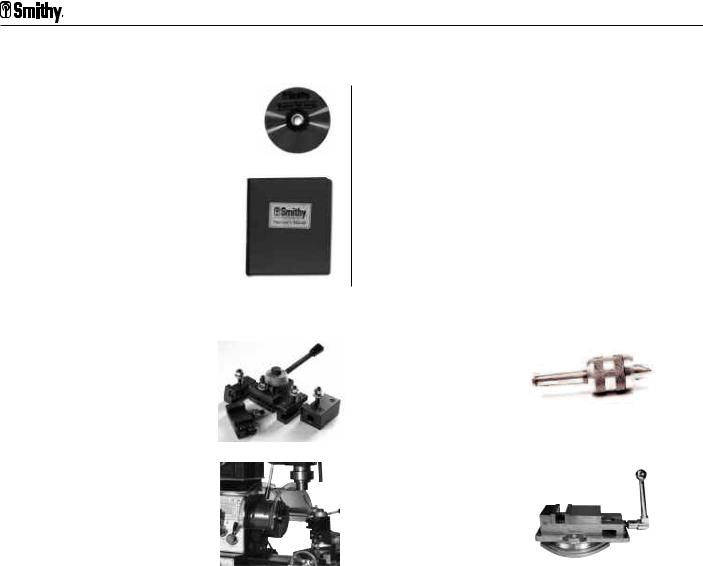
Items Packed in Plastic Bag
|
DVD, Machine |
|
OperatorÕs Manual |
|
Tool Basics |
|
Part # 83-950 |
|
Part # 12-003 |
|
Quantity 1 |
|
Quantity 1 |
|
|
Manual Cover
Part # 83-942 Quantity 1
Additional Items for GN-IMX Series
|
Quick Change |
|
Live Center** |
|
Toolpost* |
|
(Large Box) |
|
(Mounted) |
|
Part # 41-103 |
|
Part # 45-271 |
|
Quantity 1 |
|
Quantity 1 |
|
|
|
|
3Ó Superlock Vise*** |
|
|
|
|
(Large Box) |
Chuck Guard |
|
Part # K99-310 |
|
|
(Mounted) |
|
Quantity 1 |
|
|
|
|
|
Part # 15-610 |
|
|
|
Quantity 1 |
|
|
|
|
|
|
*Quick Change Toolpost replaces standard turret for IMX series.
**Live Center additional item for IMX series.
***Superlock Vise replaces angle vise for IMS series.
Missing Items?
If you find that an item is missing or defective from your Quick Start Tool Pack
Call Us TOLL FREE 1-800-476-4849 or send an e-mail to info@smithy.com
within 30 days of receiving your machine so that we may assist you immediately. Our sales and service technicians are available 8am to 5pm ET, Mondays to Fridays.
3-5 |
For Assistance: Call Toll Free 1-800-476-4849 |

Machine Overview 4
Overview
This chapter will help you to familiarize yourself with the Smithy Granite 1300 models and standard accessories. Figures 4.1 through 4.15 identify the major components and functions of your machine. The photographs in this section depict a Granite 1324 model. Distinguishing features are noted.
Major Features Identified
Millhead
Tailstock
Powerhead
Carriage
Assembly &
Compound
Angle Toolpost
Figure 4.1 Granite 1324 Front View
Or Visit www.smithy.com |
4-1 |

Granite 1300 Series Operator’s Manual
Millhead
Tailstock
Carriage
Assembly
Motor
Assembly
Figure 4.2 Granite 1324 Back View
4-2 |
For Assistance: Call Toll Free 1-800-476-4849 |

4: Machine Overview
Millhead Components & Functions
The photos below show the front and back of the millhead of the Smithy Granite machine. The millhead holds the tooling necessary to perform milling and drilling operations. The following section identifies the components and functions of the millhead.
A
B
F
 G
G
H
I  C
C
J E D
Figure 4.3 Granite Millhead (Front & Back)
A.Spindle Cover - The spindle cover protects the spindle from dust and debris. It also protects the operator from injury. The spindle cover should be in place whenever the machine is in operation. The drawbar is located under the spindle cover.
B.Millhead Cover - The Millhead cover protects the belt and pulleys of the millhead. The cover should always be in place when the machine is in operation.
C.Quill Lock - The quill lock locks the mill/drill quill in place during a horizontal milling operation or while changing tools.
D.Mill/Drill Spindle - The mill drill spindle is an R-8 taper. It holds and rotates the the tooling used during milling and drilling operation. The spindle also moves in and out of the millhead quill. The quill is an internal part which is not seen in this picture.
E.Drill Press Handles - The drill press handles move the quill in and out of the mill head during a drilling operation. Rotating the handles in a clockwise direction moves the quill downward, out of the millhead casting.
F.Coarse Feed/Fine Feed Clutch - Pulling out the coarse feed/fine feed clutch knob engages the drill press handles/coarse feed. Pressing the knob in engages drill/mill fine feed hand wheel. To easily engage/disengage the clutch, rotate the drill press handles slightly while pulling/pushing the knob.
Or Visit www.smithy.com |
4-3 |
Granite 1300 Series Operator’s Manual
G.Drill/Mill Fine Feed Handwheel - The handwheel controls the fine feed movement of the quill in and out of the millhead.
H.Height Adjustment Drive - The height adjustment drive works with the millhead crank to raise and lower the millhead. Insert the millhead crank over the stud, as in Figure 4.4, rotate clockwise to raise the millhead and counter clockwise to lower the millhead.
One revolution of the crank handle will move the millhead 0.25 inches.
Figure 4.4 Adjusting Millhead Height
I.Millhead Locking Studs - The locking studs secure the millhead in position. Insert the millhead crank over the upper stud, rotate counterclockwise to unlock the stud. Repeat the process on the lower stud. Position the millhead in the desired position and lock BOTH locking studs before starting your machine.
J.Bellows - Bellows keep debris off of the Z-Axis column and rack.
4-4 |
For Assistance: Call Toll Free 1-800-476-4849 |

4: Machine Overview
Powerhead Components & Functions
A
B 
C D E  I
I
J
H
F G
Figure 4.5 Granite Powerhead Parts (Front View)
A.Lathe/Mill Clutch - This clutch engages the mill portion of the Smithy Granite Lathe- Mill-Drill when pulled out and moved to the left. When moved to the right the lathe is engaged. Center position is neutral.
B.Speed Dial - The speed dial controls the motor rpm. Rotating clockwise increases the speed.
C.Forward/Reverse & On/Off Switch - The red toggle button underneath the yellow cover reverses the direction of the motor. The green middle button is the “power-on” button. The large red button is the stop button and cuts power to the machine.
D.Powerfeed Function Lever - Moving the lever to the left, powers the lathe powerfeed. Moving the lever to the right powers the mill powerfeed.
E.Leadscrew Rotation Direction Handle - Positioning this handle to the right causes the leadscrew to rotate clockwise. Positioning to the left causes the leadscrew to rotate counterclockwise.
F.Selector Lever 1-7 - Used in conjunction with Selector Lever I-III to set feed rate or pitch setting for cutting threads.
G.Selector Lever I-III - Used in conjunction with Selector Lever I-7 to set feed rate or pitch setting for cutting threads.
H.Jog Knob - Assists in meshing gears inside the quick change gear box which is controlled by selector levers 1-7 and I-III. Rotating the knob helps align gears
I.Oil Level/Sight Glass - Normal oil level is at the half way point, add oil if the level of oil in the sight glass drops below this level.
J.Quick Change Gear Box - Houses the gears that determine feed rates and gear settings for cutting threads.
Or Visit www.smithy.com |
4-5 |

Granite 1300 Series Operator’s Manual
A
B
C
Figure 4.6 Granite Powerhead Parts (Back View)
A.Oil Fill Port - Located directly above the motor, it holds 8-10 oz of 30 weight oil. Remove the screw to add oil as necessary.
B.Belt Tension - Moves the motor pulley up and down releasing tension on the belts. Pull the lever down to loosen the tension on the belt and push the lever up to add tension to the belts.
C.DC Motor - Runs on standard 110 volt power.
4-6 |
For Assistance: Call Toll Free 1-800-476-4849 |

4: Machine Overview
Pulley Box
L-3
L-4
L-5
L-2
L-6 |
L-10 |
L-1
L-7
L-9 L-8
Figure 4.7 Granite Pulley Box (Inside)
The pulley box houses the drive pulleys, gears and power components.
L-1. Motor Pulley - A three-step pulley attached to the shaft of the motor.
L-2. Speed Reduction Pulley - Sits between the motor and spindle pulley and is used for low speed operations when increased torque is desired.
L-3. Spindle Pulley - A two-step pulley attached to the main lathe spindle.
L-4. Change Gear A - A 30-tooth gear installed at the factory. The change gears only need to be reconfigured when cutting metric threads.
L-5. Change Gear B - A 60 tooth gear installed at the factory. The change gears only need to be reconfigured when cutting metric threads.
L-6. Change Gear C - A 66 tooth gear that rides behind change gear B (60 tooth gear) and is installed at the factory. The change gears only need to be reconfigured when cutting metric threads.
L-7. Change Gear D - A 60 tooth gear installed at the factory.
L-8. SCR Module - Converts the AC power coming into the machine to DC power for the motor.
L-9. Inch/Metric Selector - Used when cutting threads. Pull the lever out toward the operator when cutting metric threads. When cutting inch (SAE) threads, make sure the lever is pushed in toward the machine.
Or Visit www.smithy.com |
4-7 |


 Granite 1300 Series Operator’s Manual
! NOTICE !
There is a neutral position with this selector. Be sure that it is completey engaged in either the metric or inch mode before you begin your threading operation.
L-10. Leadscrew Clutch- Is designed to slip to reduce damage to the machine apron if the carriage is accidentally run into the head of the machine.
Carriage Assembly
I
A G
B E
H
D
C F
Figure 4.8 Granite Carriage Assembly
The carriage assembly consists of:
•Crossslide table
•Carriage; the lower portion of the table that rides on the bed ways,
•Apron; the portion that hangs from the cross-slide table in front of the machine.
The carriage moves by hand or by power along the bed ways. Its function is to support the cutting tool rigidly while in the lathe mode and to secure the workpiece while in the mill mode. The carriage can be locked into place with the lock found on the back of the carriage.
The figure to the above right identifies and defines the major components of the carriage assembly.
A. Cross-SlideTable - The top portion of the carriage assembly. It supports the compound angle toolpost (not pictured) which holds the lathe cutters and tooling. The table also supports your workpiece when operating the mill. The cross-slide table has four, 7/16” sized t-slots for securing tooling and mounting workpieces.
4-8 |
For Assistance: Call Toll Free 1-800-476-4849 |

4: Machine Overview
B.Cross-Slide Handwheel - This handwheel moves the table toward and away from the operator along the Y-Axis. Rotating the handwheel clockwise moves the table away from the operator while moving it counterclockwise moves the table toward the operator.
C.Longitudinal Handwheel - This handwheel is located at the bottom left of the carriage assembly. Manually rotating the handwheel clockwise will move the carriage assembly along the X-Axis towards the tailstock end of the machine. Rotating the handwheel counter clockwise will move the the carriage assembly towards the headstock end of the machine.One revolution moves the assembly approximately .040”.
NOTE: This handwheel is for coarse movements only. Use the handwheel at the end of the leadscrew for fine movement (0.001”)
D. Half-Nut Engagement Lever - This lever closes the half-nut on to the leadscrew. When the half-nut is engaged, in the down position, the table assembly will be powered to move right and left along the X-Axis leadscrew.
! NOTICE !
The half-nut engagement lever is only engaged for rapid travel or threading operations.
E.Longitudinal and Lateral Powerfeed Selector - This selector determines whether the carriage will be powered to move along the X-Axis (longitudinal axis) or the Y-Axis (lateral axis). When the lever is in the upper position the table will move along the Y-Axis. When moved into the lower position, the table will move along the X-Axis. Center position is neutral.
F.Threading Dial - The threading dial is used to coordinate consecutive cuts when cutting threads. Restarting each cut from the same point on the dial ensures that each cut follows the same path, leading to accurately machined threads.
! NOTICE !
The threading dial can only be used when cutting inch (SAE) threads.
G.Saddle - The saddle supports the cross-slide table and moves along the X-Axis of the machine.
H.Apron - The apron houses the gear mechanism for the X and Y-Axis powerfeed.
Or Visit www.smithy.com |
4-9 |


 Granite 1300 Series Operator’s Manual
Figure 4.9 Granite Carriage Gib Adjustment Screws (Quantity 4)
I. Carriage Gib Adjustment Screws - These screws press a small metal plate (the gib) to the ways of the bed, increasing or decreasing the tension when moving the cross-slide assembly. (Figure 4.9)
Figure 4.10 Granite Carriage Lock Y-Axis
J. Carriage Lock (Y-Axis) - is an M8 screw. Turning the screw clockwise will prohibit movement of the carriage along the Y-Axis. (Figure 4.10)
Figure 4.11 Granite Carriage Lock X-Axis (Rear View)
K. Carriage Lock X-Axis - is an M8 screw located on the back side of the carriage. Turning this screw clockwise locks the carriage to the bedways.
Figure 4.12 Granite Carriage Travel Indicators
L. Travel Indicators - mark the limit of travel on the crossfeed table. Running the top portion of the indicator located on the tailstock side of the cross-slide table past the lower indicator on the bottom portion of the table (carriage) will cause serious damage to your machine.
4-10 |
For Assistance: Call Toll Free 1-800-476-4849 |

4: Machine Overview
 WARNING
Do not let the top indicator mark travel past the bottom indicator mark on the right side (side facing tailstock) of the carriage assembly.
Figure 4.13 Granite Carriage Gib Adjustment Screws (Rear View)
M. Carriage Gib Adjustments Screws - when screwed in, these screws press a small metal plate (the gib) to the ways of the bed, increasing or decreasing the tension when moving the carriage assembly along the bed ways.
Carriage Assembly-Compound Angle Toolpost
A
B
I C
D E
H
 F
F
G
Figure 4.14 Granite Compound Toolpost
The compound angle toolpost is bolted to the cross-slide table with 10mm T-Bolts. The compound angle toolpost swivels to any angle horizontal to the lathe axis. The calibrations on the swivel base are in degrees, (60º-0º-60º). The following section identifies and explains the functions of the toolpost.
A. CATP (Compound Angle Toolpost) Lock down handle - The handle rotates counterclockwise to loosen the tension on the four position turret, allowing the user to turn the turret 90º per turn.
Or Visit www.smithy.com |
4-11 |

Granite 1300 Series Operator’s Manual
B.Turret Bolts - These bolts secure your tooling to the turret.
C.4 Position Turret - The turret holds up to 1/2” tooling. The turret can support up to 4 tools.
D.Compound Slide - The compound slide moves the tooling in towards and away from the workpiece.
E.Floating Dial - The floating dial can be repositioned to zero at any point to measure tool feed in or out.
F.CATP Carriage -The carriage supports the compound slide and is bolted directly to the swivel base.
G.Swivel Base - The swivel base secures the CATP and allows it to rotate 360º in either direction. A calibrated scale at the bottom of the base shows positioning in degrees from 60º-0º-60º.
H.Slide lock - This slide lock locks the compound slide to the carriage to secure the slide in position.
I.Compound Gib Adjustment Screws - These screws press a small metal plate (the gib) to the ways of the bed, increasing or decreasing the tension when moving the compound slide.
Tailstock
|
A |
C |
|
|
F |
|
|
|
|
||
|
|
|
|
|
|
|
|
|
|
E |
|
B |
|
|
|
G |
|
|
|
|
|
D |
|
|
|
|
|
|
|
|
Figure 4.15 Granite Tailstock (Front & Back) |
|
|||
|
The tailstock holds tooling that supports the end of a workpiece. It also holds tooling such |
|
as center drills, reamers and taps. It moves along the bed of the machine and can be |
|
stopped and locked in position at any point on the bedways. The photos above depict the |
|
tailstock of the Granite machine. This section will identify and define major components |
|
and functions of the Granite tailstock. |
4-12 |
For Assistance: Call Toll Free 1-800-476-4849 |

4: Machine Overview
A.Tailstock Body - This is the main casting of the tailstock.
B.Off-Setting Lock Bolts -These bolts lock the top base of gthe tailstock and prevent it from moving off center.
C.Tailstock Handwheel -This handwheel moves the tailstock barrel in and out of the tailstock body.
D.Tailstock Lock -This locks the tailstock body to the bed ways.
E.Tailstock Barrel Lock -This locks the barrel into position.
F.Tailstock Barrel -The barrel holds the MT3 tooling that supports the end of the workpiece.
G.Tailstock Off-Setting Bolts -These bolts allow the user to offset the toolpost for cutting tapers.
For Granite MAX and I-MAX Series Machines
The following are some of the modifications and improvements for the Granite MAX and Granite Industrial MAX machine series.
A.30% Longer Millhead - An extended millhead to accept larger workpieces for more efficient milling operations.
B.Crash Protection System (Y-Axis) - A unique shear pin design that protects your machine from major damage if the machine is run past its limits of travel. Found inside the carriage assembly.
C.Electrical Overload Protection - Improvement on the powerhead section of the machine that safely shut offs the machine for prolonged motor life.
D.Extended Tailstock Travel - Drill or ream deeper with 3” travel, also reach farther across the table with the center securely placed in the tailstock.
E.Quick Change Toolpost (For Idustrial MAX Series
Only) - The fastest, most convenient way to change a tool.
Or Visit www.smithy.com |
4-13 |
 Loading...